EP3597461A1 - Véhicule électrique - Google Patents
Véhicule électrique Download PDFInfo
- Publication number
- EP3597461A1 EP3597461A1 EP18184573.6A EP18184573A EP3597461A1 EP 3597461 A1 EP3597461 A1 EP 3597461A1 EP 18184573 A EP18184573 A EP 18184573A EP 3597461 A1 EP3597461 A1 EP 3597461A1
- Authority
- EP
- European Patent Office
- Prior art keywords
- electric motor
- rotor
- electric
- module
- stator
- Prior art date
- Legal status (The legal status is an assumption and is not a legal conclusion. Google has not performed a legal analysis and makes no representation as to the accuracy of the status listed.)
- Granted
Links
Images








Classifications
-
- B—PERFORMING OPERATIONS; TRANSPORTING
- B60—VEHICLES IN GENERAL
- B60K—ARRANGEMENT OR MOUNTING OF PROPULSION UNITS OR OF TRANSMISSIONS IN VEHICLES; ARRANGEMENT OR MOUNTING OF PLURAL DIVERSE PRIME-MOVERS IN VEHICLES; AUXILIARY DRIVES FOR VEHICLES; INSTRUMENTATION OR DASHBOARDS FOR VEHICLES; ARRANGEMENTS IN CONNECTION WITH COOLING, AIR INTAKE, GAS EXHAUST OR FUEL SUPPLY OF PROPULSION UNITS IN VEHICLES
- B60K1/00—Arrangement or mounting of electrical propulsion units
-
- B—PERFORMING OPERATIONS; TRANSPORTING
- B60—VEHICLES IN GENERAL
- B60K—ARRANGEMENT OR MOUNTING OF PROPULSION UNITS OR OF TRANSMISSIONS IN VEHICLES; ARRANGEMENT OR MOUNTING OF PLURAL DIVERSE PRIME-MOVERS IN VEHICLES; AUXILIARY DRIVES FOR VEHICLES; INSTRUMENTATION OR DASHBOARDS FOR VEHICLES; ARRANGEMENTS IN CONNECTION WITH COOLING, AIR INTAKE, GAS EXHAUST OR FUEL SUPPLY OF PROPULSION UNITS IN VEHICLES
- B60K1/00—Arrangement or mounting of electrical propulsion units
- B60K1/02—Arrangement or mounting of electrical propulsion units comprising more than one electric motor
-
- B—PERFORMING OPERATIONS; TRANSPORTING
- B60—VEHICLES IN GENERAL
- B60K—ARRANGEMENT OR MOUNTING OF PROPULSION UNITS OR OF TRANSMISSIONS IN VEHICLES; ARRANGEMENT OR MOUNTING OF PLURAL DIVERSE PRIME-MOVERS IN VEHICLES; AUXILIARY DRIVES FOR VEHICLES; INSTRUMENTATION OR DASHBOARDS FOR VEHICLES; ARRANGEMENTS IN CONNECTION WITH COOLING, AIR INTAKE, GAS EXHAUST OR FUEL SUPPLY OF PROPULSION UNITS IN VEHICLES
- B60K11/00—Arrangement in connection with cooling of propulsion units
- B60K11/02—Arrangement in connection with cooling of propulsion units with liquid cooling
-
- B—PERFORMING OPERATIONS; TRANSPORTING
- B60—VEHICLES IN GENERAL
- B60K—ARRANGEMENT OR MOUNTING OF PROPULSION UNITS OR OF TRANSMISSIONS IN VEHICLES; ARRANGEMENT OR MOUNTING OF PLURAL DIVERSE PRIME-MOVERS IN VEHICLES; AUXILIARY DRIVES FOR VEHICLES; INSTRUMENTATION OR DASHBOARDS FOR VEHICLES; ARRANGEMENTS IN CONNECTION WITH COOLING, AIR INTAKE, GAS EXHAUST OR FUEL SUPPLY OF PROPULSION UNITS IN VEHICLES
- B60K17/00—Arrangement or mounting of transmissions in vehicles
- B60K17/34—Arrangement or mounting of transmissions in vehicles for driving both front and rear wheels, e.g. four wheel drive vehicles
- B60K17/356—Arrangement or mounting of transmissions in vehicles for driving both front and rear wheels, e.g. four wheel drive vehicles having fluid or electric motor, for driving one or more wheels
-
- B—PERFORMING OPERATIONS; TRANSPORTING
- B60—VEHICLES IN GENERAL
- B60K—ARRANGEMENT OR MOUNTING OF PROPULSION UNITS OR OF TRANSMISSIONS IN VEHICLES; ARRANGEMENT OR MOUNTING OF PLURAL DIVERSE PRIME-MOVERS IN VEHICLES; AUXILIARY DRIVES FOR VEHICLES; INSTRUMENTATION OR DASHBOARDS FOR VEHICLES; ARRANGEMENTS IN CONNECTION WITH COOLING, AIR INTAKE, GAS EXHAUST OR FUEL SUPPLY OF PROPULSION UNITS IN VEHICLES
- B60K1/00—Arrangement or mounting of electrical propulsion units
- B60K2001/003—Arrangement or mounting of electrical propulsion units with means for cooling the electrical propulsion units
-
- B—PERFORMING OPERATIONS; TRANSPORTING
- B60—VEHICLES IN GENERAL
- B60K—ARRANGEMENT OR MOUNTING OF PROPULSION UNITS OR OF TRANSMISSIONS IN VEHICLES; ARRANGEMENT OR MOUNTING OF PLURAL DIVERSE PRIME-MOVERS IN VEHICLES; AUXILIARY DRIVES FOR VEHICLES; INSTRUMENTATION OR DASHBOARDS FOR VEHICLES; ARRANGEMENTS IN CONNECTION WITH COOLING, AIR INTAKE, GAS EXHAUST OR FUEL SUPPLY OF PROPULSION UNITS IN VEHICLES
- B60K1/00—Arrangement or mounting of electrical propulsion units
- B60K2001/003—Arrangement or mounting of electrical propulsion units with means for cooling the electrical propulsion units
- B60K2001/006—Arrangement or mounting of electrical propulsion units with means for cooling the electrical propulsion units the electric motors
-
- B—PERFORMING OPERATIONS; TRANSPORTING
- B60—VEHICLES IN GENERAL
- B60K—ARRANGEMENT OR MOUNTING OF PROPULSION UNITS OR OF TRANSMISSIONS IN VEHICLES; ARRANGEMENT OR MOUNTING OF PLURAL DIVERSE PRIME-MOVERS IN VEHICLES; AUXILIARY DRIVES FOR VEHICLES; INSTRUMENTATION OR DASHBOARDS FOR VEHICLES; ARRANGEMENTS IN CONNECTION WITH COOLING, AIR INTAKE, GAS EXHAUST OR FUEL SUPPLY OF PROPULSION UNITS IN VEHICLES
- B60K1/00—Arrangement or mounting of electrical propulsion units
- B60K1/04—Arrangement or mounting of electrical propulsion units of the electric storage means for propulsion
- B60K2001/0405—Arrangement or mounting of electrical propulsion units of the electric storage means for propulsion characterised by their position
- B60K2001/0438—Arrangement under the floor
Definitions
- the invention relates to an electric vehicle, in particular an electric car, with (a) a first axle, (b) a second axle, (c) an electric motor for driving at least one of the axles and (d) a battery for supplying the electric motor with electrical energy ,
- Electric vehicles have been manufactured for some time and are experiencing a renaissance. In comparison to vehicles with internal combustion engines, however, their share has so far been low. Even if the manufacture of electric vehicles is fundamentally simpler and more cost-effective than the manufacture of internal combustion engine vehicles, electric motors of different sizes have hitherto been used for the different performance classes in the outer dimensions.
- an electric vehicle is subject to a multitude of requirements that must be met cumulatively so that it can prevail over the existing vehicles.
- an electric vehicle should be durable, usable in a wide temperature range, robust and constructed as simply as possible.
- the electric vehicle should be as simple as possible to manufacture and ideally allow product variants to be derived in a simple manner.
- the invention has for its object to propose an improved electric vehicle.
- the invention solves the problem by a generic electric vehicle, in which (e) the electric motor is constructed from a first electric motor module and at least one second electric motor module, (f) the electric motor modules are arranged one behind the other with respect to a motor axis of rotation and have a common rotor shaft or have coupled rotor shafts and wherein (g) the first electric motor module and the second electric motor module are connected to one another by means of a plug connection which has at least one cooling medium connection for cooling medium, one data connection for data on an electrical or optical data line and at least one power connection for power current.
- this electric vehicle can be assembled particularly quickly. It is possible to quickly assemble and fix the electric motor modules together using the plug connection. In this way, the electric motor can be assembled quickly and effectively from the electric motor modules.
- the electric motor is easy to repair. If an electric motor module has failed, it can simply be removed and replaced with a new electric motor module.
- the plug connection is understood to mean a connection between two electric motor modules which is designed such that it can be closed by an axial movement.
- a connector has a male connector element and a female connector element, which together form the connector.
- the plug connection preferably comprises (a) a first axial plug connector and (b) a second axial plug connector, the first axial plug connector being arranged laterally next to the rotor shaft on a first side and the second axial plug connector being arranged on a second side opposite the first side is arranged laterally next to the rotor shaft.
- Such an arrangement leads to a low overall height.
- the at least one cooling medium connection is arranged in the first axial connector and the at least one current connection is arranged in the second axial connector. In this way, live parts are separated from fluid-carrying, especially water-carrying, parts. This increases the operational safety of the electric motor.
- the first axial connector and the second axial connector can preferably be coupled to one another by moving the electric motor modules in a coupling direction. It is particularly favorable if the coupling direction runs in the axial direction with respect to the rotor shaft. In other words, in this case it is possible to close the plug connection by moving the two electric motor modules towards one another in the axial direction. In this case, it is particularly favorable if the rotor shafts can also be coupled to one another in this way. This allows a particularly simple assembly.
- the first electric motor module preferably has a cross connector which has a cross cooling medium connection, a cross data line connection and a cross drive current connection and whose coupling direction runs transversely to the axial direction.
- the electric motor module and thus the electric motor as a whole can be easily connected via such a cross connector.
- the first axial connector prefferably has a first common connector, the first common connector surrounding at least two connections and being sealingly connected to a second common connector of the second axial connector.
- two seals are provided, for example for the cooling medium connection, namely one for the seal of the collective connector and a second time for the cooling medium connection itself. If one of the two seals becomes leaky, however, one does not occur Leakage of cooling medium.
- the cooling medium is preferably understood to mean cooling liquid, in particular cooling water.
- the cooling medium connection is preferably connected to a cooling channel which runs through the rotor shaft. It is particularly favorable in the case when the first electric motor module has a controlled, in particular regulated valve, by means of which a cooling medium flow of cooling medium can be changed. All electric motor modules preferably have corresponding valves. These valves can, for example, be proportional valves.
- the first electric motor module prefferably has an electronic assembly which is designed to energize winding heads of the electric motor module, the electric motor module in this case, in accordance with a preferred embodiment, having an assembly cooling line which is used to cool the Electronics assembly is arranged. This assembly cooling line is connected to the cooling medium connection.
- the electric motor module has a controlled, in particular regulated, assembly valve for changing the coolant flow to the electronic assembly and / or a controlled, in particular regulated, stator valve for changing the coolant flow to the stator and / or to the rotor.
- assembly valve for changing the coolant flow to the electronic assembly
- stator valve for changing the coolant flow to the stator and / or to the rotor.
- the electronic assembly preferably comprises at least one thermometer for detecting the temperature of the electronic assembly, the assembly valve preferably being designed for regulating the cooling medium flow on the basis of the temperature measured by this thermometer.
- stator and / or the rotor comprise a thermometer and the stator valve is designed to regulate the cooling medium flow on the basis of the temperature measured by this thermometer.
- the first electric motor module has a first module housing that has a first housing coupling structure
- the second electric motor module has a second module housing that has a second housing coupling structure
- the electric motor modules are positively connected to one another by means of the housing coupling structures
- a first housing coupling structure is at least partially formed by a first conical housing ring
- the second housing coupling structure is at least partially formed by a second conical housing ring is formed
- the conical housing rings connected by means of a coupling clamp are, which has an at least partially conical inner surface
- the coupling clamp is designed for positive locking connection with the housing coupling structure.
- the coupling clamp has a clamp projection for engaging in a housing recess of the housing coupling structure and / or
- the housing has a housing projection for engaging in a clamp recess of the clamp and / or
- the electric motor has a dowel pin which engages in the housing recess and the clamp recess.
- the invention solves the problem by a generic electric car, in which (e) the electric motor is constructed from a first electric motor module and at least a second electric motor module, and (f) the electric motor modules with respect to a motor -The axis of rotation are arranged one behind the other and have a common rotor shaft or have coupled rotor shafts. It is possible and preferred, but not necessary, that the (g) the first electric motor module and the second electric motor module are connected to one another by means of a plug-in connection which has at least one cooling medium connection for cooling medium, one data connection for data on one electrical or optical data line and at least one power connection for power current.
- a plug-in connection which has at least one cooling medium connection for cooling medium, one data connection for data on one electrical or optical data line and at least one power connection for power current.
- the electric motor has an electric motor height and the battery has a battery height, the electric motor height largely corresponding to the battery height.
- An advantage of this electric vehicle is that the electric motor and the battery can be arranged at the same height, which is a preferred embodiment and means that the overall height that must be provided for the electric motor and the battery can be chosen to be small. It is particularly cheap if, which is also a preferred embodiment, both the batteries and the electric motor are arranged below a level at which the driver's seat is located. In other words, the engine and battery are then completely located under the driver's seat. As a result, the center of gravity of the electric vehicle is so low that there is good road holding.
- this adaptation of the heights enables modularization of batteries and electric motor. This in turn makes it possible to efficiently plan and manufacture the production of different models with different drive powers.
- an electric vehicle is understood to mean in particular a land vehicle, for example an electric car or an electric truck.
- the electric vehicle preferably has four wheels.
- the axis is the component to which the wheels are attached.
- the mathematical axis around which the wheels rotate is called the axis of rotation.
- the height of the electric motor is calculated in particular on the basis of the imaginary cuboid of minimum volume which contains 90% of the mass of the electric motor. In other words, it is possible that smaller areas of the electric motor protrude or form projections, although this is often not advantageous.
- the battery height is calculated in the same way.
- the electric motor height largely corresponds to the battery height is understood in particular to mean that the electric motor height differs from the battery height by at most 15%.
- the quotient of the electric motor height as the numerator and the battery height as the denominator is between 0.85 and 1.15.
- the height of the electric motor is preferably smaller than the height of the battery.
- the center of gravity of the electric motor is below a seat level of a driver's seat and / or below a floor of a passenger compartment. This generally results in good road holding.
- the electric motor drives the wheels of an axle via a differential.
- more than one electric motor it is also possible for more than one electric motor to be present, at least one of the electric motors driving only one wheel. In this case, any differences in rotational speed when cornering are electronically corrected.
- An electric vehicle is preferably a vehicle whose drive torque at a constant 50 kilometers per hour comes at least 50% from the electric motor. It is particularly favorable if it is a purely electric vehicle, which means that the wheels are driven exclusively by electricity.
- the electric motor is arranged entirely between the axes.
- This is to be understood in particular to mean that the electric motor is arranged in a region which is located between two levels, each of the levels running vertically and going through the axes of rotation of the wheels of the electric vehicle when driving straight ahead. It is particularly favorable if the distance between the electric motor and the first axis deviates as little as possible, preferably at most by a factor of two, from a distance from the second axis.
- Such an electric vehicle has a particularly small moment of inertia with respect to the rotation about the vertical axis. The electric vehicle therefore has particularly advantageous driving properties.
- the distance between the front end of the electric motor, in particular the front electric motor module, with respect to the longitudinal axis of the electric vehicle, and the rearmost end of the electric motor, preferably the rearmost electric motor module, is at most 15% of the center distance.
- the electric vehicle preferably has a vehicle floor.
- the electric motor and the battery can be arranged on the vehicle floor. Alternatively, they are suspended from the vehicle floor.
- the hanging assembly has the advantage that it can be carried out particularly easily. Mounting on the vehicle floor offers advantages in protecting the batteries against external influences.
- the invention also solves the problem by a generic electric vehicle, in which the electric motor is constructed from at least two electric motor modules, the electric motor modules being arranged one behind the other with respect to a motor axis of rotation and having a plurality of coupled rotor shafts or a common rotor shaft.
- the electric motor is constructed from at least two electric motor modules, the electric motor modules being arranged one behind the other with respect to a motor axis of rotation and having a plurality of coupled rotor shafts or a common rotor shaft.
- This is an independent invention with respect to the above invention.
- the height of the electric motor corresponds largely to the height of the battery in such an electric vehicle.
- the preferred embodiments described below relate to both inventions.
- the electric motor modules are preferably of identical construction and are connected to one another.
- the height of the electric motor does not largely correspond to the height of the battery.
- the height of the electric motor can be smaller than the height of the battery. In this way, the center of gravity of the electric vehicle can be particularly low, which improves road holding.
- a shaft bearing for the continuous rotor shaft of the electric motor is preferably arranged between two electric motor modules. In this way, vibrations of the rotor are reduced when the vehicle is driving over uneven ground.
- the invention also solves the problem with an electric vehicle having (a) a first axle, (b) a second axle, (c) an electric motor for driving at least one of the axles, which has an electric motor height, and (d) a battery for supplying the electric motor with electrical energy, which has a battery height, the electric motor being an external rotor, the rotor being one, in particular T-shaped, outer portion and wherein the stator has at least one coil package which is arranged between the outer portion and the rotor shaft.
- an electric vehicle having (a) a first axle, (b) a second axle, (c) an electric motor for driving at least one of the axles, which has an electric motor height, and (d) a battery for supplying the electric motor with electrical energy, which has a battery height, the electric motor being an external rotor, the rotor being one, in particular T-shaped, outer portion and wherein the stator has at least one coil package which is arranged between the outer portion and the rotor shaft.
- the electric motor it is possible, but not necessary, for the electric motor to be constructed from a first electric motor module and at least one second electric motor module, the electric motor modules being arranged one behind the other with respect to a motor axis of rotation and having a common rotor shaft or having coupled rotor shafts. It is also possible, but not necessary, for the first electric motor module and the second electric motor module to be connected to one another by means of a plug connection which has at least one cooling medium connection for cooling medium and at least one current connection for power current.
- the T-shaped outer section can also be referred to as a rotor bell. This results in a high torque with a low overall height.
- the at least one coil package projects between the outer section and the remaining part of the rotor. It is possible, but not necessary, for the rotor bell to be symmetrical with respect to a plane of symmetry that is perpendicular to the axis of rotation of the motor.
- the electric motor height corresponds largely to the battery height and / or that the electric motor is constructed from at least two electric motor modules and the electric motor modules are arranged one behind the other with respect to a motor axis of rotation and have a common rotor shaft or have coupled rotor shafts.
- the preferred embodiments described below relate to all three inventions.
- the rotor bell and the rotor shaft are positively connected to one another.
- the rotor bell has internal teeth and the shaft of the rotor has external teeth, the rotor bell being connected to the shaft in a rotationally fixed manner by means of the internal teeth and the external teeth. This makes assembly easier.
- the outer section preferably comprises permanent magnets on its radially inward side.
- the at least one coil package is contacted electrically, mechanically and / or thermally with a cap of the stator.
- the at least one coil package is fastened to the cap of the stator in such a way that the waste heat from the coil package is actively or passively removed when the electric vehicle is in operation.
- the rotor has a hollow shaft. In this way, the vibrating mass is reduced.
- the rotor it is possible for the rotor to be cooled from the inside by sending a cooling fluid, in particular air or cooling liquid, for example water, through the hollow shaft.
- a battery center of gravity of the battery and / or an electric motor center of gravity of the electric motor is preferably between the axes, in particular in a central third, preferably a central fifth (quintile). If the vehicle is standing such that both axes extend along a horizontal plane, a first vertical plane runs such that the first axis extends along the first vertical axis. A second vertical axis extends such that the second axis extends along the second vertical axis. The two vertical axes run parallel to each other.
- the central third is the area between two further vertical axes, the distance of which corresponds to a third of the distance from the first and second vertical axes, the distance from a center, which lies exactly between the first and the second vertical axis, is the same.
- the corresponding center of mass is then arranged between these two additional vertical axes.
- Such an arrangement of the battery or of the electric motor leads to particularly favorable driving properties, since the mass moment of inertia with respect to a yaw, pitch or roll movement of the electric vehicle is particularly small.
- the passenger compartment preferably has a central tunnel-free floor. Since the battery and the electric motor have the same overall height, a central tunnel for accommodating an enlarged electric motor is unnecessary.
- the invention is based on the finding that it is advantageous to increase the torque of the electric motor by making it long. Previous vehicles rely on electric motors with the largest possible rotor diameter and a small overall length in order to increase the torque. However, this leads to a disadvantageous position of the center of gravity of the electric motor and / or makes a center tunnel necessary.
- the electric vehicle according to the invention manages without a central tunnel.
- the feature that the passenger compartment has a floor free of a central tunnel means in particular that the floor is flat in the technical sense. In other words, surveys are possible, but the maximum survey is small. In particular, the maximum elevation between the driver and front passenger seat is at most 10 centimeters above an imaginary level of compensation through the floor of the passenger compartment.
- the electric vehicle preferably has a longitudinal axis and the motor axis of rotation extends along the longitudinal axis.
- This is to be understood in particular to mean that it is possible, but not necessary, for the motor axis of rotation to extend parallel to the longitudinal axis.
- an offset angle between the motor axis of rotation and the longitudinal axis is possible, which is preferably at most 20 °, in particular at most 5 °.
- the battery preferably comprises at least two battery units, the motor axis of rotation running between the battery units.
- the feature that the motor axis of rotation runs between the battery units is understood to mean that a projection of the motor axis of rotation onto a plane along which the first axis and the second axis extend is between a first center of gravity of the first battery unit Battery unit and a second battery unit center of gravity of the second battery unit runs. It is particularly expedient if the axis of rotation runs in such a way that - based on a respective projection onto the plane along which the two axes run - the first battery unit is separated from the second battery unit. In other words, there is no galvanic Element of a battery unit from one side of the projection of the axis of rotation to the other. However, it is possible that electrical connectors, in particular cables, run from one side of the projection of the axis of rotation to the other side.
- the electric motor preferably has a rotor with permanent magnets. It is possible that the electric motor is an internal rotor motor. Alternatively, the electric motor is an external rotor motor.
- the electric vehicle preferably has a differential and a transmission, which is arranged in the torque flow between the motor and the differential. It is possible, but not necessary, for the electric vehicle to have a second differential and a second transmission, which is arranged in the torque flow between the motor and the second differential.
- the first differential preferably drives the wheels of the front axle.
- the second differential preferably drives the wheels of the rear axle.
- a four-wheel drive can be realized with two differentials.
- the first differential and / or the second differential are each rotationally rigidly coupled to the corresponding rotor of the electric motor.
- the electric motor can be manufactured particularly simply if it has a rotor with permanent magnets, the rotor having grooves running in the longitudinal direction, in which the permanent magnets are arranged. For example, the permanent magnets are inserted into the grooves.
- the electric vehicle comprises a second electric motor which is constructed from at least two second electric motor modules, the second electric motor modules having a common second rotor, and the first rotor and the second rotor run parallel to one another. It is possible that the first electric motor drives the wheels of the first axis and the second electric motor drives the wheels of the second axis. Alternatively, it is also possible for the first electric motor and the second electric motor to jointly drive the wheels of one of the axles, for example the front axle and / or the rear axle.
- the electric motor comprises a second electric motor, which is preferably made up of at least two electric motor modules, a third electric motor, which is preferably made up of at least two electric motor modules, and a fourth electric motor, which is preferably made up of at least two electric motor modules is constructed, each of the electric motors driving a wheel, in particular via an angular gear. It is advantageous if all electric motor modules are identical. It is then favorable if all the motors are controlled by a motor controller in such a way that they apply the same torque to the respective wheel, preferably preventing the wheel from spinning. Such an anti-slip control is part of the prior art and is therefore not further explained.
- the stator preferably has a base body and a second coil package, the coil package being fastened to a cap of the stator and the cap being reversibly fastened to the base body. So the electric motor is easy to assemble.
- the first electric motor module has a first rotor that has a first rotor shaft and its rotor shaft has a first shaft coupling structure
- the second electric motor module has a second rotor that has a second rotor shaft , and its second rotor shaft has a second shaft coupling structure
- the electric car comprising a rotary bearing by means of which the first rotor shaft is mounted
- the first rotor shaft and the second rotor shaft are positively coupled to one another by means of the coupling structures.
- the invention also relates to an electric motor with the properties mentioned, which is designed in particular for an electric vehicle, but this is not necessary.
- the coupling structures are preferably at least partially surrounded by the rotary bearing.
- the advantage of the invention is that the electric motor can be built very compact in this way. According to a preferred embodiment, it is possible that the connection by means of the coupling structures on the housing and on the rotor shafts does not lead to any additional axial lengthening of the overall length.
- the pivot bearing has a first pivot bearing, which has a first set of rolling elements, which are arranged in a ring, and a second pivot bearing, which has a second set of rolling elements, which are arranged in a ring and offset from the first set.
- the shaft coupling structures are preferably at least partially, particularly preferably completely surrounded by the first pivot bearing and by the second pivot bearing.
- the first pivot bearing and / or the second pivot bearing is, for example, a roller bearing, in particular a ball bearing.
- each individual electric motor module is supported on both sides by at least one roller bearing.
- the two coupling structures of the respective electric motor modules have to be connected to one another in a form-fitting manner.
- the rotary bearings of the electric motor modules which are located to the extreme, are adjacent to one another. In this way, a particularly compact electric motor is obtained. Because the electric motor can be modularized, it is well suited for use in vehicles, especially in passenger cars. However, this electric motor can also be used in other vehicles and also in other areas.
- the first shaft coupling structure preferably has a projection extending in the axial direction.
- the second shaft coupling structure preferably has a recess that also extends in the axial direction, so that the first shaft coupling structure and the second coupling structure abut one another in the axial direction along a contact surface. It is favorable if the contact surfaces with a Angle measuring plane, which contains an axis of rotation of the rotor, forms an angle of at most 5 °. In this way, axial forces are reduced, which would otherwise arise when a torque is applied to the connection of the electric motor modules.
- the projection and the recess are asymmetrical.
- a first contact surface, along which the projection and the recess rest against one another extends at a different angle relative to the angle measurement plane than the second contact surface.
- one of the angles it is possible for one of the angles to be zero. In this case there is no axial force when the rotors rotate in a first direction. On the other hand, a greater force is created when the rotors turn in the opposite direction.
- the electric motor preferably has at least one additional component that has an additional component coupling structure with a projection that extends in the axial direction, the additional component being connected to one of the coupling structures of an electric motor module in a form-fitting manner. Because the additional component has the same coupling structure as the electric motor modules, it can be placed between two electric motor modules as required.
- the additional component is, for example, an encoder.
- the electric motor accordingly has a rotary encoder which has a rotary encoder coupling structure with a projection which extends in the axial direction, the rotary encoder being positively connected to one of the coupling structures of an electric motor module. Because the encoder has the same coupling structure as the electric motor modules, it can be placed anywhere between two electric motor modules, depending on the requirements.
- the rotor shafts preferably of all electric motor modules, have coupling structures that can be coupled to one another in a form-fitting manner.
- the additional component is a brake.
- the electric motor has a brake which has a brake coupling structure with a projection which extends in the axial direction has, wherein the brake is positively connected to a coupling structure of an electric motor module or the rotary encoder.
- the additional component is a clutch.
- a second aspect of the invention relates to an electric motor which comprises a stator which has stator electromagnets and a rotor which has permanent magnets, the rotor shaft having a cooling channel.
- An electric vehicle with a corresponding electric motor is also according to the invention. It is favorable if this electric motor is constructed from a first electric motor module and a second electric motor module, the electric motor modules having the properties specified above.
- the first rotor shaft and the second rotor shaft are positively coupled to one another by means of the shaft coupling structures, the cooling channel preferably running through the first rotor and the second rotor. It is also favorable if the coupling structures are at least partially surrounded by the rotary bearing. In this way, an electric motor of modular design with cooled rotors is obtained.
- the rotor shaft prefferably has a central cooling duct running in the axial direction, a feed branch duct which runs radially outwards and is connected to the central cooling duct, and also a discharge branch duct which runs outwards and which runs with the center -Cooling duct is connected. It is possible in this way to supply cooling fluid to the stator through the feed stub channel.
- the stator preferably has a cooling fluid supply for supplying cooling fluid, in particular cooling liquid, to the supply branch passage, and a cooling fluid discharge for discharging cooling fluid from the discharge branch duct.
- the cooling fluid supply particularly preferably has a first shaft seal and a second shaft seal, which form an annular channel.
- the cooling fluid supply preferably also has a feed line which is designed to supply cooling fluid to the ring channel.
- the ring channel is arranged so that the cooling fluid flows into the feed branch channel.
- the feed stub is on an axial length arranged along a longitudinal axis of the rotor between the first shaft seal and the second shaft seal.
- the two electric motor modules are identical. If there are more than two electric motor modules, a majority of the electric motor modules are preferably, particularly cheaply, all electric motor modules of identical construction.
- At least the motor of one of the electric motor modules preferably has a magnet carrier and a plurality of permanent magnets which are fastened to the magnet carrier. It is expedient if the rotor has a secondary channel, which at least also runs through the magnet carrier in the axial direction and is connected to the central cooling channel. In this way, the magnetic carrier can be cooled effectively.
- Permanent magnets lose their magnetization above the Curie temperature. Since electric motors, especially those that are installed in electric vehicles, must also function in comparatively warm environments and, in addition, heating of the permanent magnets and the magnet carrier, in particular due to eddy current losses, must be ensured that the permanent magnets do not heat up too much. So far, this has been done by detecting the temperature and by switching off the corresponding motor when a predetermined threshold temperature, which is below the cooling temperature of the permanent magnets, has been exceeded. By cooling the magnetic carrier, this procedure is still possible and preferred, but is no longer necessary.
- the permanent magnets are arranged radially outside the stator electromagnets.
- the electric motor can then be called an external rotor.
- the rotor shaft has a first sleeve section which extends in a first axial direction and a second sleeve section which extends in a direction opposite to the first axial direction, the sleeve sections preferably being symmetrical to one another and preferably Cooling channels included. These cooling channels are preferably connected to the cooling channel, in particular the central cooling channel.
- the sleeve sections are preferably formed on a tubular component which is fastened to a web.
- the web preferably has a radially outwardly extending connecting channel which connects the central cooling channel to an outer channel in the tubular component.
- the feature that a specific object is present means in particular that at least one of these objects is present.
- the stator has a cooling nozzle which is arranged for cooling the electromagnets. Most of the heat is lost in the electromagnets. At the same time, electromagnets are generally less sensitive to temperature than permanent magnets. It is therefore possible that the cooling fluid is guided in a cooling circuit and first cools the permanent magnets, in particular the magnet carriers, and then the stator electromagnets behind a cooler in the direction of flow. Alternatively, it is also possible for two cooling circuits to exist, one cooling circuit cooling the permanent magnets and a second cooling circuit the electromagnets.
- the electric motor is constructed from at least two electric motor modules, as described above, the motors of the respective electric motor modules each having a cooling channel and the two cooling channels being connected to one another, so that cooling fluid from the first cooling channel into the second cooling channel can flow.
- the first electric motor module preferably has a first module housing which has a first housing coupling structure
- the second electric motor module having a second module housing which has a second housing coupling structure and the electric motor modules are positively connected to one another by means of their housing coupling structure. This represents a particularly simple form of coupling the electric motor modules.
- the housing coupling structures are each at least partially formed by a conical housing ring. It is expedient if the electric motor module has a connector for positively connecting the housing coupling structures to one another.
- the connector is preferably designed to be mountable from the outside. In other words, the electric motor modules can be separated from one another simply by disconnecting the connector.
- the connector can be mounted from the outside.
- the connector is preferably a clamp, so that the housing coupling structures are connected to one another by means of the clamp.
- the clamp preferably has an at least partially conical inner surface, the conical inner surface generally being designed such that there is no line contact, but rather a flat contact between the housing rings on the one hand and the clamp on the other.
- the first rotor shaft and the second rotor shaft, and optionally further components of the electric motor, which are coupled by means of the shaft coupling structures, are preferably coupled with axial play.
- Axial changes in length on the rotors due to manufacturing tolerances or thermal changes in length during operation are compensated for by a defined axial play in the shaft coupling structure.
- An independent object of the present invention is an electric vehicle, in particular an electric car, having (a) a first axis, (b) a second axis, (c) an electric motor for driving at least one of the axes and (d) a battery for supplying the electric motor with electrical energy, wherein (e) the electric motor is constructed from a first electric motor module and at least one second electric motor module, preferably at least one third electric motor module, wherein (f) the electric motor modules one behind the other with respect to a motor axis of rotation are arranged, wherein (g) the electric motor modules have a common rotor shaft or have coupled rotor shafts, where (h) each electric motor module has at least one stator thermometer for measuring the temperature in a stator and / or a rotor thermometer for measuring the Has temperature in a rotor of the respective electric motor module, wherein (i) the electric vehicle has a motor controller which is designed to control the electric motor modules depending on the temperatures measured by the thermometers.
- first electric motor module and the second electric motor module are connected to one another by means of a plug connection which has at least one cooling medium connection for cooling medium and at least one current connection for power current.
- a plug connection which has at least one cooling medium connection for cooling medium and at least one current connection for power current.
- Each electric motor module preferably comprises at least one electronic assembly for energizing the stators, in particular at least one winding head of the stator, so that the electric motor module emits a torque.
- the motor controller is set up to automatically control the electronic assemblies, so that a first torque that a first electric motor module outputs is less than a second torque that a second electric motor module outputs when a first temperature in the first Electric motor module, for example the first rotor temperature of the rotor and / or the first stator temperature of the stator, exceeds a predetermined warning threshold value. It can thus be achieved that the drive torque of the electric motor is provided by the electric motor modules with the lowest temperatures, which slows down the aging of the electric motor modules.
- the motor controller is designed to automatically control the electronic assemblies, so that an electric motor module whose rotor temperature exceeds a rotor alarm temperature threshold value and / or whose stator temperature exceeds a stator alarm temperature threshold value, is not energized. In this way, a further rise in the temperature is avoided and the electric vehicle can still continue to drive if at least one electric motor module is still functional.
- each electric motor module has an assembly thermometer for measuring a temperature of the electronics assembly for energizing the winding heads of the stator. All thermometers are connected to the motor control for recording the temperature measurements. If the temperature of the electronics module exceeds a predefined module alarm temperature threshold value, the motor controller controls the corresponding electric motor module in such a way that the electrical current is reduced, in particular to zero. This reduces the thermal load on the module and prevents it from burning out. If the temperature of the electronics module falls below a switch-on value, the motor controller controls the electronics module so that it again outputs a torque.
- Figure 1a shows an electric vehicle 10 according to the invention in the form of an electric car, which has a first axle 12 in the form of a front axle and a second axle 14 in the form of a rear axle. Wheels 16.1, 16.2 are fastened to the first axis 12, wheels 16.3, 16.4 are fastened to the second axis 14.
- An electric motor 18 drives the wheels 16.1, 16.2 of the first axle 12 via a differential gear 20, which can also be called a differential.
- the electric motor 18 is powered by a battery 22.
- the battery 22 comprises at least two, in the present case eight, battery units 24.1, 24.2, ..., 24.8.
- a motor axis of rotation D 18 runs between the battery units 24.1, 24.3, 24.5, 24.7 on the one hand and 24.2, 24.4, 24.6 and 24.8 on the other.
- a mass m r of the battery units 24.1, 24.3, 24.5 and 24.7 arranged on the right side of the motor rotation axis D 18 corresponds to a mass m l of the battery elements on the left of the motor rotation axis D 18 , that is to say in the present case the battery elements 24.2, 24.4, 24.6 and 24.8.
- the feature that the two masses m r , m l correspond to one another means in particular that the two masses differ from one another by at most 20%, preferably at most 15%. This is - regardless of other features - a preferred feature of the invention.
- the electric vehicle 10 has a vehicle floor 26. In the present embodiment, both the battery 22 and the electric motor 18 are mounted on the vehicle floor 26.
- the electric vehicle 10 also includes components not shown, such as an outer shell, in particular made of sheet metal, and Seats and a steering.
- the electric motor 18 is preferably constructed as described below.
- Figure 1b shows the electric vehicle 10 in a view from the rear. It can be seen that an electric motor height h M corresponds to a battery height h B. The electric motor height h M is the height of the imaginary cuboid Q 1 of minimum volume, which encloses 90% of the mass of the battery 22.
- Figure 1b also shows a body 28 of the electric vehicle 10. Also shown is a driver's seat 30 and a passenger's seat 32, both of which are arranged on a floor 34 of a passenger compartment 36. The floor 34 is flat in the present case, but this is not necessary.
- Figure 1c shows a modified embodiment of the electric vehicle 10, in which the battery center of gravity S 22 lies above the electric motor center of gravity S 18 .
- parts of the battery 22 in the present case namely the battery modules 24.8 and 24.9, are arranged at least partially above the electric motor 18.
- the additional modules can be, for example, replacement battery modules that can be removed without the functionality of the electric vehicle 10 being impaired.
- the battery modules 24.8, 24.9 can be batteries that are kept as additional accessories of the electric vehicle 10 in order to increase the range of the electric vehicle 10.
- the seat 30 has a seat plane E 30 , along which a seat surface of the seat 30 extends.
- Most driver seats 30 are adjustable in height.
- the seat level E 30 refers to the level that lies between the levels that correspond to the extreme settings of the driver's seat 30.
- the seat plane 30 in this case is the plane along which the seat surface of the driver's seat 30 extends in the middle setting. The fact that the center of gravity of the electric motor is below the seat level results in particularly favorable road holding.
- the electric motor modules 38.i are identical.
- Figure 1d shows that the electric vehicle 10 has an additional transmission 42 between the differential transmission 20 and the electric motor 18.
- the electric motor can be operated at higher speeds than without the gear 42, which is accordingly preferably a reduction gear.
- Figure 1e shows a further embodiment of an electric vehicle 10 according to the invention, in which the coupled rotor shafts 41 (cf. Figure 1d ) of the electric motor 18 are connected to both the differential 20 and a second differential 44 in a rotationally rigid manner.
- the end of the coupled rotor shaft 41 is connected to the second differential 44 via a second gear 46.
- Figure 1f shows a fourth embodiment of an electric vehicle 10 according to the invention, which has a second electric motor 18 '.
- the second electric motor comprises three electric motor modules 38'.1, 38'.2 and 38'.3.
- the two electric motor modules 38'.1 and 38'.3 are identical in construction.
- the continuous rotor shaft 40 ' runs parallel to the continuous rotor shaft 40 in the technical sense, which means that small deviations of, for example, at most 5 ° can be tolerated.
- Both continuous rotor shafts 40 and 40 'and thus the associated motor axes of rotation D 18 , D' 18 also run - as in the other embodiments - along a longitudinal axis L of the electric vehicle 10.
- the first coupling gear 52 is rotationally rigidly coupled to the first differential 20
- the second coupling gear 54 is rotationally rigidly connected to the second differential 44.
- Figure 1g shows a fifth embodiment of an electric vehicle 10 according to the invention, in which 4 electric motors 18.1, 18.2, 18.3 and 18.4 are used.
- the first electric motor 18.1 drives the first wheel 16.1 and the second electric motor 18.2 drives the second wheel 16.2.
- the third electric motor 18.3 drives the third wheel 16.3 and the fourth electric motor 18.4 drives the fourth wheel 16.4.
- the electric vehicle 10 also has a schematically shown motor controller 58, which is connected to all the electric motors and the battery.
- the motor controller 58 is designed to control all electric motors 18.1, ..., 18.4, so that when the electric vehicle 10 is cornering, the different angular velocities of the wheels lead to adapted speeds of the respective electric motors, so that the slip is the same for all wheels 16.i and im Ideally is zero. It is possible that each electric motor is made up of two or more identical electric motor modules.
- All of the electric vehicles shown have a battery mass center of gravity S 22 (cf. Fig. 1a ) between the axes 12, 14.
- a distance of the battery center of gravity S 22 from a vehicle center of gravity S 10 is at most a quarter of an axis distance A of the two axes 12, 14.
- an electric motor center of gravity S 18 is tight at the center of gravity of the vehicle S 16 , in particular in a central quintile Q along the longitudinal axis L between the axes 12, 14.
- FIG. 1b shows that the battery 22, in particular its galvanic cells, are not located below the electric motor 18.
- all battery modules 24.i are arranged either to the right or to the left of the electric motor 18 with respect to the longitudinal axis L, but not above or below it.
- FIG. 2a shows two successive electric motor modules 38.1 and 38.2 in the version of an inner rotor and shaft bearings 60.1, 60.2, with which the continuous rotor shaft 40 is supported and on the vehicle floor 26 (cf. Fig. 4 . 5 ) is attached. It can be seen that the electric motor modules 38.1, 38.2 can be removed by means of detachable fastening elements, in the present case in the form of screws 62.1, ....
- Figure 2b shows in a vertical section through an electric motor module of the internal rotor version that 40 permanent magnets 64.1 ... are inserted into the grooves 50.1, 50.2 .... of the continuous rotor shaft, which are excited to rotate by the coil package 48.
- Figure 2c shows a side view of the electric motor modules 38.1 and 38.2 of the inner rotor version.
- FIG. 3 shows two successive electric motor modules 38.1 and 38.2 of the external rotor version, the stator 66 of which has a base body 68 and a first cap 70.1 and a second cap 70.2.
- the caps 70.1, 70.2 are reversibly attached to the base body 68 with screws 62.1, 62.2, ..., 62.8.
- Each cap 70.i is firmly connected to at least one stator coil package.
- Figure 3b shows like the other partial figures of the Figure 3 a scale view of the rotor 39, which comprises a shaft 72 in the form of a hollow shaft.
- the shaft 72 has an external toothing 74 on which a rotor bell 78 is seated with an internal toothing 76.
- the rotor bell 78 forms a T-shaped outer section of the rotor 39.
- the rotor 39 also has a second rotor bell 78 '.
- the electric motor comprises at least three rotor bells.
- the permanent magnets of the rotor are not shown for the sake of clarity.
- Figure 3c shows a section through the electric motor module 38.1 of the external rotor version. It can be seen that the permanent magnets 64 are arranged on the inside of a jacket section 80 of the rotor bell 78. These are from the Stator coil package 48 moves. For example, the permanent magnets 64.i are inserted into grooves in the radially inward side of the jacket section 80.
- Figure 3d shows a sectional view through the electric motor modules 38.1 and 38.2 of the external rotor version with the T-shaped rotor bells 78 and 78 '. It can be seen that coils 82.i are rigidly mechanically and also thermally connected to the cap 70 of the stator 66. In other words, at least one coil package 48, which comprises the coils 82.i, is fastened to the cap 70 of the stator 66 in such a way that waste heat from the coil package 48 is actively or passively removed during operation of the electric vehicle.
- the electric motor 18 is constructed from three electric motor modules 38.1, 38.2, 38.3 which are coupled one behind the other. All three electric motor modules 38.1, 38.2, 38.3 are identical in construction and have rotor shafts 40.1, 40.2, 40.3 coupled to one another.
- Figure 1e shows that the electric vehicle 10 has a first clutch 177.1 and a second clutch 177.2.
- the first clutch lies in a torque path between the electric motor 18 and the wheels 16.1, 16.2 of the first axis 12.
- the second clutch 177.2 lies in a torque path between the electric motor 18 and the wheels 16.3 and 16.4 of the second axis 14.
- the clutches 177.1, 177.2 are preferably electrically switchable. In this way, it is possible for the electric vehicle 10 to have either a pure front-wheel drive or a pure rear-wheel drive or all-wheel drive.
- the Figure 1f shows a reduced perspective view to scale of an electric vehicle according to the invention according to a further embodiment, which has two electric motors 18.1, 18.2.
- the Figure 1g shows a reduced perspective view to scale of an electric vehicle according to the invention according to a further embodiment, which has four electric motors 18.1, ..., 18.4.
- the electric motors 18.1, 18.2 consist of at least two modules, the respective axes of rotation of which run parallel to one another. However, it is a parallel in the technical sense, which means that it is possible, but not necessary, that the two axes run parallel to each other in the mathematical sense. In particular, the axes of rotation can form an angle with one another that is, for example, less than 3 °.
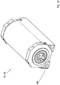
- Figure 4a shows an electric motor module 38.1 of the inner rotor version, which has a first rotor 142 (cf. Figure 2b ) and a module housing 144.
- a first coupling structure 146a is formed on the rotor shaft 40 of the rotor 142.
- the module housing 144 comprises housing rings 148a.1, 148b.1, which can also be referred to as coupling rings.
- the housing ring 148a.1 is formed on a stator cap 150a.1.
- the module housing 144 also comprises a second stator cap 150b.1 and a stator carrier 152 which is connected to both stator caps 150a.1, 150b.1 and is arranged between the two in the embodiment of the inner rotor version shown.
- the suffix ".1" indicates that the corresponding object belongs to the electric motor module 38.1.
- shaft coupling structure 146 projects partially axially beyond the module housing 144 and partially springs back behind the module housing 144.
- Figure 4b shows the rotor 142 with the shaft coupling structure 146a.1 and a second shaft coupling structure 146b.1, which is arranged opposite the first coupling structure 146a.
- the rotor 142 has a magnet carrier 154, by means of which permanent magnets 156.1, 156.2 are arranged.
- Figure 4b also shows that the first coupling structure 146b.1 has a projection 158.1 extending in the axial direction. In the assembled state, this projection 158.1 lies along two contact surfaces K1, K2 on a complementary coupling structure of the adjacent electric motor module.
- the contact surfaces K1, K2 form an angle between 0 ° and an angle measuring plane E in the present case and 1 °.
- the angle measurement plane E is a plane which contains an axis of rotation D of the rotor 142 and which touches or intersects the respective contact surface K at at least one point.
- the rotor 142 also has a first bearing seat 160.1 and a second bearing seat 160.2.
- Figure 5a shows a cross section through an embodiment of an electric motor 18 according to the invention as an internal rotor version, which is constructed from electric motor modules 38.1, 38.2, which are each identical in construction.
- the first electric motor module 38.1 has a first pivot bearing 162a.1 in the form of a ball bearing and a second pivot bearing 162b.1.
- the second electric motor module 38.2 has a rotary bearing 162a.2 and a second rotary bearing 162b.2.
- the first rotary bearing 162a.1 has a first set of rolling elements 164.1, 164.2, ... which are arranged in a ring.
- the second rotary bearing 162b.2 also has rolling elements 166.1, 166.2, ... which are arranged along a second ring which is offset from the first ring.
- the two rotary bearings 162a.1 and 162b.2 form a rotary bearing 168.
- the coupling structure 146a of the first electric motor module 38.1 forms a positive connection with a coupling structure 146b.2 of the second electric motor module 38.2 and that the coupling structures 146a .1, 146b.2 are surrounded by the rotary bearing 168.
- Figure 5a shows that the coupling structure 146a.1 of the first electric motor module 38.1 extends below the pivot bearing 162b.2 of the second electric motor module 38.2. This represents a generally preferred embodiment, regardless of other features of the embodiment described here. In addition, the coupling structure 146b.2 extends below the pivot bearing 162a.1.
- Figure 5b shows a section Figure 5a
- the module housing 144.1 has a first housing coupling structure 170a.1, which forms a first conical housing ring.
- the second module housing 144.2 has a second housing coupling structure 170b.2, which likewise forms a second conical housing ring.
- the two housing coupling structures 170a.1, 170b.2 are positively connected by means of a connector in the form of a coupling clamp 172.
- the coupling clamp 172 has a conical inner surface 174 which has respective surface contacts with the housing coupling structures 170a.1, 170b.2 and thus brings about a positive fit.
- Figure 5b also shows that an axial length L1 is less than twice, here less than 1.5 times an axial length L2 of a coupling section.
- the axial length L2 corresponds to the axial length of the shaft coupling.
- An axial length L3 of the coupling clamp 172 is smaller by a small amount than the axial length L2.
- the coupling clamp 172 is designed so that it can be loosened and tightened from the outside. It is thereby possible to connect two electric motor modules 38.1, 38.2 by first connecting the rotor shafts to one another by means of their respective shaft coupling structures. The housings are then connected to one another by means of the connector, in this case the coupling clamp 172. To release the connection between the two electric motor modules 38.1, 38.2, only the coupling clamp 172 has to be removed, then the rotor shafts can be pulled apart axially.
- Figures 6a, 6b show an electric motor according to the invention, which comprises three electric motor modules 38.1, 38.2 and 38.3 as well as a rotary encoder 176, a clutch 177 and a brake 178.
- the rotary encoder 176 and the brake 178 each have a shaft which run coaxially with the rotor shafts of the electric motor modules 38.i.
- Figure 6b shows a partial exploded view of the electric motor 18 according to FIG Figure 6a , It can be seen that the rotary encoder 176 has rotary encoder coupling structures 180a, 180b which correspond to the coupling structures 146 of the electric motor modules 38.
- the brake 178 has at least one brake coupling structure 182a, which is also constructed like the other coupling structures, so that the brake 178 can be positively connected both to the rotary encoder 176 and to each electric motor module 38.
- the clutch 177 has the same coupling structure as the brake 178, so that it can be coupled to any electric motor module like the brake 178.
- FIG. 7 shows a cross section through the electric motor module 38.1 as an inner rotor version, which can also be regarded as an independent electric motor. It can be seen that a cooling channel 184 is arranged in the rotor shaft 40. In the present form, a cooling fluid 186 in the form of a cooling liquid is fed axially through a cooling fluid supply 188. A sealing bushing 190 rotates with the rotor shaft and is connected to the rotor shaft 40 via seals.
- At least one, preferably two, partition walls 192a, 192b are arranged in the rotor shaft 40, which result in the cooling fluid 186 flowing through a first secondary channel 194a, a second secondary channel 194b or another secondary channel (not shown).
- the secondary channels 194a, 194b, ... run in the axial as well as in the radial direction and thus largely parallel to the cooling channel 184.
- the cooling fluid in the secondary channel 194 cools the magnet carrier 154 and thus the permanent magnets 156.
- a stator laminated core 196 is arranged radially outside of the permanent magnets 156.
- the stator laminated core 196 is cooled in a stator cooling duct 198 by means of cooling fluids. It is possible that the stator cooling duct 198 does not extend over the full width of the stator lamination stack, in particular winding heads 100a, 100b do not have to lie on an axial length on which the stator cooling duct 198 also extends.
- FIG 8 shows a further embodiment of an electric motor module 38 according to the invention in the external rotor version, which at the same time represents an independent embodiment of an electric motor according to the invention. While it is according to the electric motor Figure 7 is an inner rotor, it is about according to the electric motor 38 Figure 8 around an external rotor, in which the permanent magnets 156 are arranged radially outside the stator laminated core 196.
- the stator laminations 196a, 196b engage in a space between the rotor shaft 40 and a tubular component 102, which has a first sleeve section 104 and a second sleeve section 106.
- the tubular component 102 is fastened to a web 108, which can also be referred to as a rotor hub.
- the tubular component 102 and the web 108 form a T-shaped rotor element.
- the rotor shaft 40 has a feed branch channel 110, by means of which the cooling fluid 186 can be guided into the cooling channel 184.
- the dividing walls 192a, 192b, 192c cause the cooling fluid from the branch passage 110 to initially cover a part in the cooling passage 184 and then to flow into a first web passage 112, from where it can flow into a duct (not shown) in the tubular component 102 , There, the cooling fluid heats up and flows through a second web channel 114 in web 108 back into the channel 184.
- the cooling fluid flows from the rotor 142 into a shaft ring channel 129 between the stator housing 121 and the rotor shaft 40 and from there via a discharge branch channel 115 a cooling fluid drain 118.
- the cooling fluid 186 arrives via a cooling fluid supply 120 to the feed branch channel 110.
- the cooling fluid supply 120 is also formed in a stator housing 121, in the present case in the stator cap 150b1.
- the cooling fluid supply 120 comprises a first shaft seal 122 and a second shaft seal 124.
- the second shaft seal 124 also serves to seal the rotary bearing 162b.1.
- Figure 9a shows an isometric view of the rotor 142 of the module 38.1. It can be seen that the tubular component 102 by means of screws 126.1, 126.2 on the web 108 (cf. Figure 9b ) is attached.
- Figure 9b shows the web channels 112, 114, between which a web ring channel 128 is arranged. Cooling fluid flows from the web ring channel 128 into the open component 102 and back from there, so that it reaches the second web channel 114.
- Figure 10 shows a cross section through an electric motor 18 according to the invention, which is constructed from two electric motor modules 38.1, 38.2 of the external rotor version.
- FIG 11a shows a part of the stator housing 121, consisting of stator cap 150 and stator carrier 152, which has an inflow 132 for cooling fluid and an outflow 133 for cooling fluid and has a cooling support 130
- Figure 9 the cooling sockets of the electric motor 18 are also drawn in and here, as in the case of the other components which are present more than once, are identified both with the counting suffixes "a" and "b” and “.1” and “.2". The purpose of this count is to make it possible to name duplicate objects as easily as possible.
- the stator electromagnets 134 (cf. Figures 7 and 9 ) of the electric motors, which are external rotors, cooled.
- Figure 11b shows a cross section through the stator cap 150 and the rotor shaft 40 to show the shaft ring channel 129.
- Figure 12 shows a further embodiment of an electric motor module 38, in which the shaft coupling structure 146 is formed with multiple teeth.
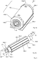
- Figure 13 shows two electric motor modules 38.1, 38.2, the first electric motor module 38.1 having a first axial connector 200 and a second axial connector 202. Both axial plug connectors 200, 202 form a plug connection 204.
- the first axial plug connector 200 is arranged laterally next to the rotor shaft 40 on a first side S1.
- the second axial connector 202 is arranged on a second side S2. The two sides S1, S2 are separated from one another by the rotor shaft 40.
- the first axial connector 200 consists of a male connector element 206m and a female connector element 206w.
- the plug connection 204 has a cooling medium connection 208 which has a male part 208m and a female part 208w.
- the cooling medium connection includes a forward line and a return line. The forward line is provided with the reference number 208, the return line with the reference number 208 '.
- the plug connection 204 also has a power connection 210 which comprises the power connector elements 212m, 212w, 214m, 214w and 216m, 216w for the positive pole, the negative pole and the earth conductor.
- All components of the power connection 210 include sealing elements for fluid-tight sealing.
- the sealing elements are made, for example, from entropy-elastic material, in particular a plastic such as silicone.
- the connector 204 comprises a data connection 218, which comprises a male data connector element 220m and a female data connector element 220w.
- the data connection 218 is also liquid-tight.
- the first axial plug connector 200 has a first collective plug connector 222, which in the present embodiment surrounds the data connection 218 and the current connection 210.
- the second axial connector 202 comprises a second common connector 224 and a signal connection 226m, 226w ..
- Figure 13 also shows that the shaft coupling structure 146b.2 with an axial length L2 partly inside and partly outside the housing length G (see Fig. 8 ) of the electric motor module 38.2.
- the length L2 is preferably between 5 and 30 millimeters.
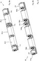
- Figure 14 shows three electric motor modules 38.1, 38.2, 38.2, the electric motor modules 38.1, 38.2 being connected by means of the plug connection 204.
- the electric motor modules 38.2, 38.3 are connected by means of an identically constructed plug connection 204 '.
- By moving two electric motor modules 38.1, 38.2 against a coupling direction K these can be separated from one another.
- the electric motor modules 38.1, 38.2 are coupled to one another by moving in the coupling direction K.
- the electric motor modules 38.1, 38.2 are connected by means of the coupling clamp 172.
- Figure 13 shows that the coupling clamp 172 has a first clamp projection 228a and a second clamp projection 228b which engage in respective housing recesses 230a, 230b.
- the two electric motor modules 38.1, 38.2 are connected to one another in a rotationally fixed manner.
- the projections it is also possible for the projections to be formed on the coupling clamp 172 and for the recesses in the housing coupling structure 170, in the present case in the housing ring 148b.1 and in the housing ring 148a.2.
- Another option is to use the rotatable connection as in Figure 15 shown to train.
- FIG 14 shows that the electric motor 18 on the electric motor module 38.1 has cross connectors 232, the connections of which correspond to those of the plug connection 214.
- the connections are each connected to one another, so that through the cross connector 232, for example, a cooling medium to a cooling channel, for example the cooling channel 184 (cf. Figure 7 ), can be supplied.
- the cooling medium supplied in this way can be routed to the second electric motor module 38.2 via the plug connection 214 and to the electric motor module 38.3 by means of the plug connection 204 '.
- Figure 15 15a shows a front view of the electric motor module 38.1 with the two axial plug connectors 200, 202.
- Figure 15b shows a section through the assembled coupling bracket 172. It can be seen that the housing coupling structure 170, to which the housing ring 148b.2 belongs, has a first dowel pin 234.1 and a second dowel pin 234.2, which each have a housing recess and a Engage the clamp recess and thus guarantee a non-rotatable connection of the electric motor modules.
- the alignment pin 234.1 is shown in an isometric view.
- Figure 15c shows a view of the electric motor module 38.1 from the rear without the coupling clamp.
- Figure 16 shows the cooling circuit of the electric motor module 38.1.
- the cooling channel 184 is supplied by a supply channel 236 with cooling medium, which can also be referred to as cooling fluid.
- the supply channel 236 is connected to the cooling medium connections 208, 208 '.
- Figure 16 also shows that the electric motor module 38.1 has an assembly valve 238 with which the flow of cooling fluid to a electronic assembly 204 can be changed.
- the electronic assembly contains power electronic components for energizing the electromagnets of the electric motor module. It is possible for the electronic assembly to have two or more subgroups, as in Figure 16 is indicated by the dashed areas.
- the electronics module 240 is designed to energize winding heads 100a, 100b (cf. Figure 7 ).
- the electric motor module also includes a stator valve 242, by means of which a coolant flow to the stator can be controlled or regulated.
- the electric motor module - which corresponds to a preferred embodiment - also has a rotor valve 244, by means of which the flow of cooling medium to the rotor 142 (cf. Figure 4b ) is adjustable.
- Each electric motor module 38.i has an electronics module 240, which is designed to energize the winding heads of the stators 66.1, 66.2, and a cooling module 241 for cooling the electronics module 240.
- the cooling module 241 also cools the stators 66.1, 66.2 and the rotor 142.
- the cooling assembly 241 is connected to the cooling medium connection 208.
- the cooling assembly 241 is preferably laterally opposite the electronics assembly 240, but other arrangements are also possible.
- Figure 17 shows an alternative cooling scheme for an electric motor module of an electric motor for an electric vehicle according to the invention.
- Encoder 176 The signals of the in Figure 6 Encoder 176 shown are forwarded via a data line which is connected to the data connection 218.
- the encoder 176 has the same plug connection 204, so that the encoder 176 can be installed anywhere between two electric motor modules.
- the brake 178 shown is controlled via signals which also run on the data line which is in contact with the data connection 218.
- FIG 17 shows schematically that at least one thermometer, in the present case two thermometers 246, 246 ', are arranged in the electronics module 240 can. Additional thermometers 248, 250 can be arranged, for example, in one of the winding heads or in the rotor.
- thermometers 246, 246 ' are electronic thermometers for measuring the temperature T 240 of the electronic assembly 240.
- the thermometer 248 is a stator thermometer for measuring the temperature T 66.1 of the stator 66.1, in particular the winding head of the stator 66.1.
- the winding head could also be referred to as a winding and generates a magnetic field when electrical current flows through it.
- the thermometer 250 is a rotor thermometer for measuring the temperature T 142 of the rotor 142.
- thermometers The temperatures T 240 , T 66.1 , T 142 measured by the thermometers are converted into digital signals and also transmitted via the signal line.
- the electronics module 240 is connected to the motor controller 58.
- the motor control 58 detects a torque request from an accelerator pedal of the electric vehicle, by means of which a driver can specify the torque output of the motor.
- the motor controller 58 detects a first stator temperature of the stator, in particular the stator electromagnet 134 and / or a first rotor temperature of the rotor 142, for example on the basis of a cooling water temperature of the cooling water that cools the rotor 142.
- the motor controller 58 controls the electronic assemblies of the electric motor modules 38.i in such a way that the sum of all torques of the electric motor modules 38.i corresponds to the torque requirement and that the electric current in such electric motor modules 38.i, in which the first stator temperature exceeds a predetermined warning threshold value and / or the rotor temperature is less than a predetermined warning threshold value than in electric motor modules 38.i, for which this does not apply.
- the motor controller 58 controls the electronic assemblies of the electric motor modules 38.i in such a way that the higher the temperatures in the corresponding electric motor module 38.i, the smaller the electrical current, at least in the mean.
Landscapes
- Engineering & Computer Science (AREA)
- Chemical & Material Sciences (AREA)
- Combustion & Propulsion (AREA)
- Transportation (AREA)
- Mechanical Engineering (AREA)
- Electric Propulsion And Braking For Vehicles (AREA)
Priority Applications (1)
| Application Number | Priority Date | Filing Date | Title |
|---|---|---|---|
| EP18184573.6A EP3597461B1 (fr) | 2018-07-19 | 2018-07-19 | Véhicule électrique |
Applications Claiming Priority (1)
| Application Number | Priority Date | Filing Date | Title |
|---|---|---|---|
| EP18184573.6A EP3597461B1 (fr) | 2018-07-19 | 2018-07-19 | Véhicule électrique |
Publications (2)
| Publication Number | Publication Date |
|---|---|
| EP3597461A1 true EP3597461A1 (fr) | 2020-01-22 |
| EP3597461B1 EP3597461B1 (fr) | 2021-04-21 |
Family
ID=63012953
Family Applications (1)
| Application Number | Title | Priority Date | Filing Date |
|---|---|---|---|
| EP18184573.6A Active EP3597461B1 (fr) | 2018-07-19 | 2018-07-19 | Véhicule électrique |
Country Status (1)
| Country | Link |
|---|---|
| EP (1) | EP3597461B1 (fr) |
Cited By (8)
| Publication number | Priority date | Publication date | Assignee | Title |
|---|---|---|---|---|
| CN113199936A (zh) * | 2021-06-18 | 2021-08-03 | 一汽解放汽车有限公司 | 车用冷却系统管路分配设计方法、车用冷却系统 |
| DE102020116661A1 (de) | 2020-06-24 | 2022-02-17 | Witzenmann Gmbh | Lageranordnung in einem Elektromotor, Elektromotor mit einer solchen Lageranordnung und Verwendung eines Elektromotors |
| DE102022109719A1 (de) | 2022-04-22 | 2023-10-26 | Schaeffler Technologies AG & Co. KG | Wärmetauscheranordnung mit einem eine Blechplatte aufweisenden Kühlkörper mit integriertem Kühlkanal; sowie elektrisches Antriebssystem |
| EP4501674A1 (fr) | 2023-08-03 | 2025-02-05 | Gottfried Knaus | Unité d'entraînement pour véhicule électrique |
| DE102023207996A1 (de) * | 2023-08-22 | 2025-02-27 | Zf Friedrichshafen Ag | Koppelanordnung, elektrische Maschinenanordnung sowie Fahrzeug |
| DE102023123834A1 (de) | 2023-09-05 | 2025-03-06 | Audi Aktiengesellschaft | Maschinenanordnung sowie entsprechende Radachse für ein Kraftfahrzeug mit einer Maschinenanordnung |
| EP4538080A3 (fr) * | 2023-10-10 | 2025-04-23 | Mazda Motor Corporation | Automobile électrique |
| DE102024206980A1 (de) * | 2024-07-24 | 2026-01-29 | Volkswagen Aktiengesellschaft | Antriebsaggregat für ein Kraftfahrzeug |
Citations (6)
| Publication number | Priority date | Publication date | Assignee | Title |
|---|---|---|---|---|
| EP1049235A2 (fr) * | 1999-04-27 | 2000-11-02 | Aisin Aw Co., Ltd. | Unité d'entraínement |
| DE102005011848A1 (de) * | 2004-03-22 | 2005-11-17 | General Motors Corp., Detroit | Elektromechanisches Hybridfahrzeuggetriebe mit mehreren modularen Motoren/Generatoren, die aus gleichen Komponenten zusammengebaut sind |
| US20070273225A1 (en) * | 2003-11-20 | 2007-11-29 | Philip Head | Electric Motors for Powering Downhole Tools |
| DE102013204766A1 (de) * | 2013-03-19 | 2014-09-25 | Robert Bosch Gmbh | Elektrische Fahrzeugachsenvorrichtung |
| US20150155801A1 (en) * | 2009-08-31 | 2015-06-04 | Robert Ross | Multiple Induction Electric Motor And Vehicle |
| EP2732535B1 (fr) * | 2011-07-14 | 2018-11-07 | Tchervenkov, Jean I. | Ensemble roue définissant un moteur/générateur |
-
2018
- 2018-07-19 EP EP18184573.6A patent/EP3597461B1/fr active Active
Patent Citations (6)
| Publication number | Priority date | Publication date | Assignee | Title |
|---|---|---|---|---|
| EP1049235A2 (fr) * | 1999-04-27 | 2000-11-02 | Aisin Aw Co., Ltd. | Unité d'entraínement |
| US20070273225A1 (en) * | 2003-11-20 | 2007-11-29 | Philip Head | Electric Motors for Powering Downhole Tools |
| DE102005011848A1 (de) * | 2004-03-22 | 2005-11-17 | General Motors Corp., Detroit | Elektromechanisches Hybridfahrzeuggetriebe mit mehreren modularen Motoren/Generatoren, die aus gleichen Komponenten zusammengebaut sind |
| US20150155801A1 (en) * | 2009-08-31 | 2015-06-04 | Robert Ross | Multiple Induction Electric Motor And Vehicle |
| EP2732535B1 (fr) * | 2011-07-14 | 2018-11-07 | Tchervenkov, Jean I. | Ensemble roue définissant un moteur/générateur |
| DE102013204766A1 (de) * | 2013-03-19 | 2014-09-25 | Robert Bosch Gmbh | Elektrische Fahrzeugachsenvorrichtung |
Cited By (9)
| Publication number | Priority date | Publication date | Assignee | Title |
|---|---|---|---|---|
| DE102020116661A1 (de) | 2020-06-24 | 2022-02-17 | Witzenmann Gmbh | Lageranordnung in einem Elektromotor, Elektromotor mit einer solchen Lageranordnung und Verwendung eines Elektromotors |
| CN113199936A (zh) * | 2021-06-18 | 2021-08-03 | 一汽解放汽车有限公司 | 车用冷却系统管路分配设计方法、车用冷却系统 |
| DE102022109719A1 (de) | 2022-04-22 | 2023-10-26 | Schaeffler Technologies AG & Co. KG | Wärmetauscheranordnung mit einem eine Blechplatte aufweisenden Kühlkörper mit integriertem Kühlkanal; sowie elektrisches Antriebssystem |
| DE102022109719B4 (de) | 2022-04-22 | 2024-08-08 | Schaeffler Technologies AG & Co. KG | Elektrisches Antriebssystem mit einer Wärmetauscheranordnung mit einem eine Blechplatte aufweisenden Kühlkörper mit integriertem Kühlkanal |
| EP4501674A1 (fr) | 2023-08-03 | 2025-02-05 | Gottfried Knaus | Unité d'entraînement pour véhicule électrique |
| DE102023207996A1 (de) * | 2023-08-22 | 2025-02-27 | Zf Friedrichshafen Ag | Koppelanordnung, elektrische Maschinenanordnung sowie Fahrzeug |
| DE102023123834A1 (de) | 2023-09-05 | 2025-03-06 | Audi Aktiengesellschaft | Maschinenanordnung sowie entsprechende Radachse für ein Kraftfahrzeug mit einer Maschinenanordnung |
| EP4538080A3 (fr) * | 2023-10-10 | 2025-04-23 | Mazda Motor Corporation | Automobile électrique |
| DE102024206980A1 (de) * | 2024-07-24 | 2026-01-29 | Volkswagen Aktiengesellschaft | Antriebsaggregat für ein Kraftfahrzeug |
Also Published As
| Publication number | Publication date |
|---|---|
| EP3597461B1 (fr) | 2021-04-21 |
Similar Documents
| Publication | Publication Date | Title |
|---|---|---|
| EP3597461B1 (fr) | Véhicule électrique | |
| EP3766164B1 (fr) | Véhicule électrique | |
| DE102018109966B4 (de) | Drahtlose radinterne-elektrobaugruppen mit integrierter radinterner-kühlung und fahrzeuge, die diese enthalten | |
| EP0706461B1 (fr) | Unite d'entrainement | |
| EP1717090B1 (fr) | Véhicule à toutes roues motrices | |
| DE69315507T2 (de) | Antriebssystem für ein elektrisches Fahrzeug | |
| DE102021103829A1 (de) | Fahrzeugsystem mit mehreren elektrischen antriebsachsen | |
| DE102005046763A1 (de) | Rollenantrieb und Rollentransporteinrichtung | |
| DE102021203379A1 (de) | Kühlanordnung für eine elektrische antriebsbaugruppeeines arbeitsfahrzeugs | |
| DE102018111624A1 (de) | Integriertes Antriebssystem | |
| DE102021200039A1 (de) | Elektrische maschine mit konfigurierbarer stator-/rotorkühlung | |
| DE102015207435A1 (de) | Trennsystem und -verfahren mit elektromagnetischen Impulsen | |
| DE212017000137U1 (de) | Elektroantriebsstrang, Getriebe und Fahrzeug | |
| DE102016203439A1 (de) | Radseitige Drehungstrennanordnung für einen Antriebsstrang | |
| DE102018109422A1 (de) | Wärmeaustauschbaugruppe für fahrzeugbatterie | |
| DE102014112277A1 (de) | Elektromotor | |
| DE102017120827A1 (de) | Vorrichtungstemperaturverwaltungsbaugruppe und verfahren | |
| DE112017006070T5 (de) | Antriebseinheitsbaugruppe | |
| EP2588338A2 (fr) | Système d'entraînement pour véhicule électrique | |
| EP4229743A1 (fr) | Moteur électrique plat pour entraîner une jante | |
| DE102018201822A1 (de) | Elektrisches Antriebssystem für ein elektrisch betriebenes Fahrzeug und Verfahren zum Herstellen eines elektrischen Antriebssystems für ein elektrisch betriebenes Fahrzeug | |
| DE102011081511B4 (de) | Radnabenantriebssystem mit integriertem Kühlsystem | |
| DE102010024191A1 (de) | Antriebssystem für ein Kraftfahrzeug | |
| EP1561051A1 (fr) | Dispositif d'entrainement de vehicule | |
| DE102021111525A1 (de) | Differentialbaugruppe ölmanagement-einsatz |
Legal Events
| Date | Code | Title | Description |
|---|---|---|---|
| PUAI | Public reference made under article 153(3) epc to a published international application that has entered the european phase |
Free format text: ORIGINAL CODE: 0009012 |
|
| STAA | Information on the status of an ep patent application or granted ep patent |
Free format text: STATUS: THE APPLICATION HAS BEEN PUBLISHED |
|
| AK | Designated contracting states |
Kind code of ref document: A1 Designated state(s): AL AT BE BG CH CY CZ DE DK EE ES FI FR GB GR HR HU IE IS IT LI LT LU LV MC MK MT NL NO PL PT RO RS SE SI SK SM TR |
|
| AX | Request for extension of the european patent |
Extension state: BA ME |
|
| STAA | Information on the status of an ep patent application or granted ep patent |
Free format text: STATUS: REQUEST FOR EXAMINATION WAS MADE |
|
| 17P | Request for examination filed |
Effective date: 20200630 |
|
| RBV | Designated contracting states (corrected) |
Designated state(s): AL AT BE BG CH CY CZ DE DK EE ES FI FR GB GR HR HU IE IS IT LI LT LU LV MC MK MT NL NO PL PT RO RS SE SI SK SM TR |
|
| GRAP | Despatch of communication of intention to grant a patent |
Free format text: ORIGINAL CODE: EPIDOSNIGR1 |
|
| STAA | Information on the status of an ep patent application or granted ep patent |
Free format text: STATUS: GRANT OF PATENT IS INTENDED |
|
| INTG | Intention to grant announced |
Effective date: 20201117 |
|
| GRAS | Grant fee paid |
Free format text: ORIGINAL CODE: EPIDOSNIGR3 |
|
| GRAA | (expected) grant |
Free format text: ORIGINAL CODE: 0009210 |
|
| STAA | Information on the status of an ep patent application or granted ep patent |
Free format text: STATUS: THE PATENT HAS BEEN GRANTED |
|
| AK | Designated contracting states |
Kind code of ref document: B1 Designated state(s): AL AT BE BG CH CY CZ DE DK EE ES FI FR GB GR HR HU IE IS IT LI LT LU LV MC MK MT NL NO PL PT RO RS SE SI SK SM TR |
|
| REG | Reference to a national code |
Ref country code: GB Ref legal event code: FG4D Free format text: NOT ENGLISH |
|
| REG | Reference to a national code |
Ref country code: CH Ref legal event code: EP |
|
| REG | Reference to a national code |
Ref country code: DE Ref legal event code: R096 Ref document number: 502018004871 Country of ref document: DE |
|
| REG | Reference to a national code |
Ref country code: IE Ref legal event code: FG4D Free format text: LANGUAGE OF EP DOCUMENT: GERMAN |
|
| REG | Reference to a national code |
Ref country code: AT Ref legal event code: REF Ref document number: 1384279 Country of ref document: AT Kind code of ref document: T Effective date: 20210515 |
|
| REG | Reference to a national code |
Ref country code: LT Ref legal event code: MG9D |
|
| REG | Reference to a national code |
Ref country code: NL Ref legal event code: MP Effective date: 20210421 |
|
| PG25 | Lapsed in a contracting state [announced via postgrant information from national office to epo] |
Ref country code: BG Free format text: LAPSE BECAUSE OF FAILURE TO SUBMIT A TRANSLATION OF THE DESCRIPTION OR TO PAY THE FEE WITHIN THE PRESCRIBED TIME-LIMIT Effective date: 20210721 Ref country code: NL Free format text: LAPSE BECAUSE OF FAILURE TO SUBMIT A TRANSLATION OF THE DESCRIPTION OR TO PAY THE FEE WITHIN THE PRESCRIBED TIME-LIMIT Effective date: 20210421 Ref country code: LT Free format text: LAPSE BECAUSE OF FAILURE TO SUBMIT A TRANSLATION OF THE DESCRIPTION OR TO PAY THE FEE WITHIN THE PRESCRIBED TIME-LIMIT Effective date: 20210421 Ref country code: HR Free format text: LAPSE BECAUSE OF FAILURE TO SUBMIT A TRANSLATION OF THE DESCRIPTION OR TO PAY THE FEE WITHIN THE PRESCRIBED TIME-LIMIT Effective date: 20210421 Ref country code: FI Free format text: LAPSE BECAUSE OF FAILURE TO SUBMIT A TRANSLATION OF THE DESCRIPTION OR TO PAY THE FEE WITHIN THE PRESCRIBED TIME-LIMIT Effective date: 20210421 |
|
| PG25 | Lapsed in a contracting state [announced via postgrant information from national office to epo] |
Ref country code: PL Free format text: LAPSE BECAUSE OF FAILURE TO SUBMIT A TRANSLATION OF THE DESCRIPTION OR TO PAY THE FEE WITHIN THE PRESCRIBED TIME-LIMIT Effective date: 20210421 Ref country code: NO Free format text: LAPSE BECAUSE OF FAILURE TO SUBMIT A TRANSLATION OF THE DESCRIPTION OR TO PAY THE FEE WITHIN THE PRESCRIBED TIME-LIMIT Effective date: 20210721 Ref country code: PT Free format text: LAPSE BECAUSE OF FAILURE TO SUBMIT A TRANSLATION OF THE DESCRIPTION OR TO PAY THE FEE WITHIN THE PRESCRIBED TIME-LIMIT Effective date: 20210823 Ref country code: LV Free format text: LAPSE BECAUSE OF FAILURE TO SUBMIT A TRANSLATION OF THE DESCRIPTION OR TO PAY THE FEE WITHIN THE PRESCRIBED TIME-LIMIT Effective date: 20210421 Ref country code: RS Free format text: LAPSE BECAUSE OF FAILURE TO SUBMIT A TRANSLATION OF THE DESCRIPTION OR TO PAY THE FEE WITHIN THE PRESCRIBED TIME-LIMIT Effective date: 20210421 Ref country code: SE Free format text: LAPSE BECAUSE OF FAILURE TO SUBMIT A TRANSLATION OF THE DESCRIPTION OR TO PAY THE FEE WITHIN THE PRESCRIBED TIME-LIMIT Effective date: 20210421 Ref country code: GR Free format text: LAPSE BECAUSE OF FAILURE TO SUBMIT A TRANSLATION OF THE DESCRIPTION OR TO PAY THE FEE WITHIN THE PRESCRIBED TIME-LIMIT Effective date: 20210722 Ref country code: IS Free format text: LAPSE BECAUSE OF FAILURE TO SUBMIT A TRANSLATION OF THE DESCRIPTION OR TO PAY THE FEE WITHIN THE PRESCRIBED TIME-LIMIT Effective date: 20210821 |
|
| REG | Reference to a national code |
Ref country code: DE Ref legal event code: R097 Ref document number: 502018004871 Country of ref document: DE |
|
| PG25 | Lapsed in a contracting state [announced via postgrant information from national office to epo] |
Ref country code: ES Free format text: LAPSE BECAUSE OF FAILURE TO SUBMIT A TRANSLATION OF THE DESCRIPTION OR TO PAY THE FEE WITHIN THE PRESCRIBED TIME-LIMIT Effective date: 20210421 Ref country code: EE Free format text: LAPSE BECAUSE OF FAILURE TO SUBMIT A TRANSLATION OF THE DESCRIPTION OR TO PAY THE FEE WITHIN THE PRESCRIBED TIME-LIMIT Effective date: 20210421 Ref country code: SK Free format text: LAPSE BECAUSE OF FAILURE TO SUBMIT A TRANSLATION OF THE DESCRIPTION OR TO PAY THE FEE WITHIN THE PRESCRIBED TIME-LIMIT Effective date: 20210421 Ref country code: SM Free format text: LAPSE BECAUSE OF FAILURE TO SUBMIT A TRANSLATION OF THE DESCRIPTION OR TO PAY THE FEE WITHIN THE PRESCRIBED TIME-LIMIT Effective date: 20210421 Ref country code: DK Free format text: LAPSE BECAUSE OF FAILURE TO SUBMIT A TRANSLATION OF THE DESCRIPTION OR TO PAY THE FEE WITHIN THE PRESCRIBED TIME-LIMIT Effective date: 20210421 Ref country code: CZ Free format text: LAPSE BECAUSE OF FAILURE TO SUBMIT A TRANSLATION OF THE DESCRIPTION OR TO PAY THE FEE WITHIN THE PRESCRIBED TIME-LIMIT Effective date: 20210421 Ref country code: RO Free format text: LAPSE BECAUSE OF FAILURE TO SUBMIT A TRANSLATION OF THE DESCRIPTION OR TO PAY THE FEE WITHIN THE PRESCRIBED TIME-LIMIT Effective date: 20210421 |
|
| PLBE | No opposition filed within time limit |
Free format text: ORIGINAL CODE: 0009261 |
|
| STAA | Information on the status of an ep patent application or granted ep patent |
Free format text: STATUS: NO OPPOSITION FILED WITHIN TIME LIMIT |
|
| REG | Reference to a national code |
Ref country code: CH Ref legal event code: PL |
|
| 26N | No opposition filed |
Effective date: 20220124 |
|
| PG25 | Lapsed in a contracting state [announced via postgrant information from national office to epo] |
Ref country code: MC Free format text: LAPSE BECAUSE OF FAILURE TO SUBMIT A TRANSLATION OF THE DESCRIPTION OR TO PAY THE FEE WITHIN THE PRESCRIBED TIME-LIMIT Effective date: 20210421 |
|
| REG | Reference to a national code |
Ref country code: BE Ref legal event code: MM Effective date: 20210731 |
|
| PG25 | Lapsed in a contracting state [announced via postgrant information from national office to epo] |
Ref country code: LI Free format text: LAPSE BECAUSE OF NON-PAYMENT OF DUE FEES Effective date: 20210731 Ref country code: CH Free format text: LAPSE BECAUSE OF NON-PAYMENT OF DUE FEES Effective date: 20210731 |
|
| PG25 | Lapsed in a contracting state [announced via postgrant information from national office to epo] |
Ref country code: IS Free format text: LAPSE BECAUSE OF FAILURE TO SUBMIT A TRANSLATION OF THE DESCRIPTION OR TO PAY THE FEE WITHIN THE PRESCRIBED TIME-LIMIT Effective date: 20210821 Ref country code: LU Free format text: LAPSE BECAUSE OF NON-PAYMENT OF DUE FEES Effective date: 20210719 Ref country code: AL Free format text: LAPSE BECAUSE OF FAILURE TO SUBMIT A TRANSLATION OF THE DESCRIPTION OR TO PAY THE FEE WITHIN THE PRESCRIBED TIME-LIMIT Effective date: 20210421 |
|
| PG25 | Lapsed in a contracting state [announced via postgrant information from national office to epo] |
Ref country code: IT Free format text: LAPSE BECAUSE OF FAILURE TO SUBMIT A TRANSLATION OF THE DESCRIPTION OR TO PAY THE FEE WITHIN THE PRESCRIBED TIME-LIMIT Effective date: 20210421 Ref country code: IE Free format text: LAPSE BECAUSE OF NON-PAYMENT OF DUE FEES Effective date: 20210719 Ref country code: BE Free format text: LAPSE BECAUSE OF NON-PAYMENT OF DUE FEES Effective date: 20210731 |
|
| PG25 | Lapsed in a contracting state [announced via postgrant information from national office to epo] |
Ref country code: CY Free format text: LAPSE BECAUSE OF FAILURE TO SUBMIT A TRANSLATION OF THE DESCRIPTION OR TO PAY THE FEE WITHIN THE PRESCRIBED TIME-LIMIT Effective date: 20210421 |
|
| PG25 | Lapsed in a contracting state [announced via postgrant information from national office to epo] |
Ref country code: HU Free format text: LAPSE BECAUSE OF FAILURE TO SUBMIT A TRANSLATION OF THE DESCRIPTION OR TO PAY THE FEE WITHIN THE PRESCRIBED TIME-LIMIT; INVALID AB INITIO Effective date: 20180719 |
|
| PGFP | Annual fee paid to national office [announced via postgrant information from national office to epo] |
Ref country code: GB Payment date: 20230724 Year of fee payment: 6 |
|
| PG25 | Lapsed in a contracting state [announced via postgrant information from national office to epo] |
Ref country code: MK Free format text: LAPSE BECAUSE OF FAILURE TO SUBMIT A TRANSLATION OF THE DESCRIPTION OR TO PAY THE FEE WITHIN THE PRESCRIBED TIME-LIMIT Effective date: 20210421 |
|
| REG | Reference to a national code |
Ref country code: AT Ref legal event code: MM01 Ref document number: 1384279 Country of ref document: AT Kind code of ref document: T Effective date: 20230719 |
|
| PG25 | Lapsed in a contracting state [announced via postgrant information from national office to epo] |
Ref country code: MT Free format text: LAPSE BECAUSE OF FAILURE TO SUBMIT A TRANSLATION OF THE DESCRIPTION OR TO PAY THE FEE WITHIN THE PRESCRIBED TIME-LIMIT Effective date: 20210421 |
|
| PGFP | Annual fee paid to national office [announced via postgrant information from national office to epo] |
Ref country code: FR Payment date: 20240724 Year of fee payment: 7 |
|
| PG25 | Lapsed in a contracting state [announced via postgrant information from national office to epo] |
Ref country code: AT Free format text: LAPSE BECAUSE OF NON-PAYMENT OF DUE FEES Effective date: 20230719 |
|
| PG25 | Lapsed in a contracting state [announced via postgrant information from national office to epo] |
Ref country code: AT Free format text: LAPSE BECAUSE OF NON-PAYMENT OF DUE FEES Effective date: 20230719 |
|
| GBPC | Gb: european patent ceased through non-payment of renewal fee |
Effective date: 20240719 |
|
| PG25 | Lapsed in a contracting state [announced via postgrant information from national office to epo] |
Ref country code: GB Free format text: LAPSE BECAUSE OF NON-PAYMENT OF DUE FEES Effective date: 20240719 |
|
| PG25 | Lapsed in a contracting state [announced via postgrant information from national office to epo] |
Ref country code: TR Free format text: LAPSE BECAUSE OF FAILURE TO SUBMIT A TRANSLATION OF THE DESCRIPTION OR TO PAY THE FEE WITHIN THE PRESCRIBED TIME-LIMIT Effective date: 20210421 |
|
| PGFP | Annual fee paid to national office [announced via postgrant information from national office to epo] |
Ref country code: DE Payment date: 20260114 Year of fee payment: 8 |
|
| PGFP | Annual fee paid to national office [announced via postgrant information from national office to epo] |
Ref country code: AT Payment date: 20260410 Year of fee payment: 5 |
|
| PG25 | Lapsed in a contracting state [announced via postgrant information from national office to epo] |
Ref country code: FR Free format text: LAPSE BECAUSE OF NON-PAYMENT OF DUE FEES Effective date: 20250731 |