EP3597471A1 - Moteur linéaire à stator long - Google Patents
Moteur linéaire à stator long Download PDFInfo
- Publication number
- EP3597471A1 EP3597471A1 EP18184227.9A EP18184227A EP3597471A1 EP 3597471 A1 EP3597471 A1 EP 3597471A1 EP 18184227 A EP18184227 A EP 18184227A EP 3597471 A1 EP3597471 A1 EP 3597471A1
- Authority
- EP
- European Patent Office
- Prior art keywords
- transport vehicle
- linear motor
- guide
- transport
- long stator
- Prior art date
- Legal status (The legal status is an assumption and is not a legal conclusion. Google has not performed a legal analysis and makes no representation as to the accuracy of the status listed.)
- Withdrawn
Links
Images
Classifications
-
- B—PERFORMING OPERATIONS; TRANSPORTING
- B60—VEHICLES IN GENERAL
- B60L—PROPULSION OF ELECTRICALLY-PROPELLED VEHICLES; SUPPLYING ELECTRIC POWER FOR AUXILIARY EQUIPMENT OF ELECTRICALLY-PROPELLED VEHICLES; ELECTRODYNAMIC BRAKE SYSTEMS FOR VEHICLES IN GENERAL; MAGNETIC SUSPENSION OR LEVITATION FOR VEHICLES; MONITORING OPERATING VARIABLES OF ELECTRICALLY-PROPELLED VEHICLES; ELECTRIC SAFETY DEVICES FOR ELECTRICALLY-PROPELLED VEHICLES
- B60L13/00—Electric propulsion for monorail vehicles, suspension vehicles or rack railways; Magnetic suspension or levitation for vehicles
- B60L13/04—Magnetic suspension or levitation for vehicles
- B60L13/06—Means to sense or control vehicle position or attitude with respect to railway
-
- H—ELECTRICITY
- H02—GENERATION; CONVERSION OR DISTRIBUTION OF ELECTRIC POWER
- H02K—DYNAMO-ELECTRIC MACHINES
- H02K41/00—Propulsion systems in which a rigid body is moved along a path due to dynamo-electric interaction between the body and a magnetic field travelling along the path
- H02K41/02—Linear motors; Sectional motors
- H02K41/03—Synchronous motors; Motors moving step by step; Reluctance motors
- H02K41/031—Synchronous motors; Motors moving step by step; Reluctance motors of the permanent magnet type
-
- B—PERFORMING OPERATIONS; TRANSPORTING
- B65—CONVEYING; PACKING; STORING; HANDLING THIN OR FILAMENTARY MATERIAL
- B65G—TRANSPORT OR STORAGE DEVICES, e.g. CONVEYORS FOR LOADING OR TIPPING, SHOP CONVEYOR SYSTEMS OR PNEUMATIC TUBE CONVEYORS
- B65G54/00—Non-mechanical conveyors not otherwise provided for
- B65G54/02—Non-mechanical conveyors not otherwise provided for electrostatic, electric, or magnetic
-
- B—PERFORMING OPERATIONS; TRANSPORTING
- B60—VEHICLES IN GENERAL
- B60L—PROPULSION OF ELECTRICALLY-PROPELLED VEHICLES; SUPPLYING ELECTRIC POWER FOR AUXILIARY EQUIPMENT OF ELECTRICALLY-PROPELLED VEHICLES; ELECTRODYNAMIC BRAKE SYSTEMS FOR VEHICLES IN GENERAL; MAGNETIC SUSPENSION OR LEVITATION FOR VEHICLES; MONITORING OPERATING VARIABLES OF ELECTRICALLY-PROPELLED VEHICLES; ELECTRIC SAFETY DEVICES FOR ELECTRICALLY-PROPELLED VEHICLES
- B60L13/00—Electric propulsion for monorail vehicles, suspension vehicles or rack railways; Magnetic suspension or levitation for vehicles
- B60L13/003—Crossings; Points
-
- B—PERFORMING OPERATIONS; TRANSPORTING
- B60—VEHICLES IN GENERAL
- B60L—PROPULSION OF ELECTRICALLY-PROPELLED VEHICLES; SUPPLYING ELECTRIC POWER FOR AUXILIARY EQUIPMENT OF ELECTRICALLY-PROPELLED VEHICLES; ELECTRODYNAMIC BRAKE SYSTEMS FOR VEHICLES IN GENERAL; MAGNETIC SUSPENSION OR LEVITATION FOR VEHICLES; MONITORING OPERATING VARIABLES OF ELECTRICALLY-PROPELLED VEHICLES; ELECTRIC SAFETY DEVICES FOR ELECTRICALLY-PROPELLED VEHICLES
- B60L13/00—Electric propulsion for monorail vehicles, suspension vehicles or rack railways; Magnetic suspension or levitation for vehicles
- B60L13/03—Electric propulsion by linear motors
-
- B—PERFORMING OPERATIONS; TRANSPORTING
- B65—CONVEYING; PACKING; STORING; HANDLING THIN OR FILAMENTARY MATERIAL
- B65G—TRANSPORT OR STORAGE DEVICES, e.g. CONVEYORS FOR LOADING OR TIPPING, SHOP CONVEYOR SYSTEMS OR PNEUMATIC TUBE CONVEYORS
- B65G21/00—Supporting or protective framework or housings for endless load-carriers or traction elements of belt or chain conveyors
- B65G21/20—Means incorporated in, or attached to, framework or housings for guiding load-carriers, traction elements or loads supported on moving surfaces
- B65G21/2009—Magnetic retaining means
-
- B—PERFORMING OPERATIONS; TRANSPORTING
- B65—CONVEYING; PACKING; STORING; HANDLING THIN OR FILAMENTARY MATERIAL
- B65G—TRANSPORT OR STORAGE DEVICES, e.g. CONVEYORS FOR LOADING OR TIPPING, SHOP CONVEYOR SYSTEMS OR PNEUMATIC TUBE CONVEYORS
- B65G35/00—Mechanical conveyors not otherwise provided for
- B65G35/08—Mechanical conveyors not otherwise provided for comprising trains of unconnected load-carriers, e.g. belt sections, movable in a path, e.g. a closed path, adapted to contact each other and to be propelled by means arranged to engage each load-carrier in turn
-
- H—ELECTRICITY
- H02—GENERATION; CONVERSION OR DISTRIBUTION OF ELECTRIC POWER
- H02K—DYNAMO-ELECTRIC MACHINES
- H02K41/00—Propulsion systems in which a rigid body is moved along a path due to dynamo-electric interaction between the body and a magnetic field travelling along the path
- H02K41/02—Linear motors; Sectional motors
-
- E—FIXED CONSTRUCTIONS
- E01—CONSTRUCTION OF ROADS, RAILWAYS, OR BRIDGES
- E01B—PERMANENT WAY; PERMANENT-WAY TOOLS; MACHINES FOR MAKING RAILWAYS OF ALL KINDS
- E01B25/00—Tracks for special kinds of railways
- E01B25/30—Tracks for magnetic suspension or levitation vehicles
- E01B25/32—Stators, guide rails or slide rails
Definitions
- the invention relates to a long stator linear motor with a transport path along which at least one transport vehicle is arranged to be movable in the direction of movement, the long stator linear motor having at least one holding structure with drive coils on which a passive part of the transport vehicle is arranged, the long stator linear motor having a guide surface running along the transport path and one has a guide track running along the transport route, the passive part having at least one first drive magnet, which is arranged parallel to the guide surface with the release of an air gap, the transport vehicle having at least one first profile element which is arranged on the guide track and by a contact force acting in a transverse direction is positioned on the guide track with respect to a climbing direction normal to the direction of movement and the transverse direction, and at least one running element n Passive part to ensure the air gap is supported against the attractive force acting between the drive magnets and the drive coils on the holding structure.
- a transport route of the type mentioned at the beginning in which the transport vehicle has at least a first one Auxiliary guide organ which, in cooperation with an auxiliary guide provided on the holding structure at least in divergence and / or convergence areas of the transport route, limits movement of the transport vehicle in a positive and / or negative climbing direction at least on one side.
- the transport trolley can also pass through areas of the transport route in which the pressure force of the profiled member on the guide track itself would not be sufficient to keep the transport trolley securely on track.
- a “guide track” is a shaped element that runs along the transport route and has a negative (i.e. recessed) profile, a positive (i.e. raised) profile or a combination of negative and positive profile parts.
- the “profiled member” is the counterpart, which is arranged on the passive part and matches the guide track and cooperates with it, which can be designed in particular as a profiled sliding element or as a profiled roller.
- the profile element and the guide track are designed in such a way that the force component of the attraction force acting in the transverse direction (i.e. along the y axis) between the drive coils and the drive magnets is deflected into a force acting in the z direction. This force acting in the z direction can absorb a force component acting in the negative z direction of the weight of the transport vehicle and the goods transported thereon.
- the auxiliary guide element can advantageously be spaced apart from the auxiliary guide if the profile element is centered on or in the guide track. As a result, the auxiliary guide does not generate any disruptive friction in route areas where the pressure force is sufficiently high.
- the auxiliary guide can only be provided in divergence and / or convergence areas of the transport route.
- Such divergence and / or convergence areas are required in particular for switches that can be set without mechanically moving parts.
- the features of the invention are implemented specifically in the route areas where they are required.
- the first running element can advantageously be attached to the guide surface.
- the combination of profile element and running element facilitates the insertion of the transport vehicle and ensures a defined distribution of the pressure force.
- a second running member arranged opposite the first running member in the transverse direction and / or a second auxiliary guiding member arranged opposite the first auxiliary guiding member in the transverse direction and / or a second profiling member arranged opposite the first profiling member in the transverse direction and / or a first driving magnet in FIG Second drive magnet arranged opposite one another in the transverse direction.
- the “holding structure” is generally used to denote the unit on stationary parts of the long-stator linear motor.
- the term thus encompasses active elements, in particular the drive coils (or the stator) and their fastening, as well as all route guidance elements on which the transport carriages slide or roll.
- first and / or second profile element, the first and / or second running element and / or the first and / or second auxiliary guide element can be designed independently of one another as a roller, as a sliding element or as a combination of roller and sliding element.
- the counteracting attachment areas are designed as sliding guides.
- Corresponding plain bearings can be designed, for example, as dry or air bearings.
- At least one profile element can be designed as a combined sliding / rolling element, the axis of rotation of which is arranged centrally in the passive part, the profile element protruding in the transverse direction on both sides from the passive part.
- This allows a very slim construction of the passive part.
- the contact pressure is very high in the single-comb area, the profile organ being a pure rolling element, and very low in the double-comb areas, the profile organ then being able to act as a sliding element on both sides.
- At least one running element can be designed as a combined sliding / rolling element, the axis of rotation of which is arranged centrally in the passive part, the running element protruding in the transverse direction on both sides from the passive part.
- the invention further relates to a transport vehicle with the features listed above for the transport vehicle.
- the transport vehicle and the long stator linear motor are related products that work together and complement each other.
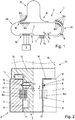
- the Fig.1 shows an exemplary conveyor application with a long stator linear motor 1 with a transport path 2, along which a number of transport vehicles Tn, with n ⁇ 1, can be moved.
- a transport path 2 is formed by drive coils Sm arranged next to one another in the direction of movement x (m stands for an index from 1 to the number of drive coils), which are attached to a stationary holding structure 3 (in Fig.1 only indicated) are arranged.
- the drive coils Sm can be controlled by a system control unit 5 (in Fig.1 only indicated for some drive coils) in order to energize them in order to generate a moving magnetic field.
- Drive magnets 4 are arranged on the transport vehicle Tn (seen in the transverse direction y) and interact in a known manner with the magnetic field generated by the drive coils Sm for moving the transport vehicle Tn. To move a transport vehicle Tn, preferably only the drive coils Sm are energized in the area of the drive magnets 4 of a transport vehicle Tn.
- the Cartesian coordinate system used x, y, z is a coordinate system that is moved along with the transport vehicle Tn.
- x always points in the direction of movement of the transport vehicle Tn, which is essentially predetermined by the transport route 2.
- the direction of movement is of course the tangent to the curvature.
- the direction of movement x can in principle be oriented in space depending on the design of the transport route 2.
- y denotes the transverse direction transverse to the direction of movement x and in the direction of the air gap 10 between the drive magnet 4 on the transport vehicle Tn and the drive coils Sm on the transport path 2.
- the plane of the air gap 10 will be parallel to the xz plane and the y direction normal to the plane of the air gap.
- the orientation of the axes of the coordinate system is of course not limited to the execution of the figures, but is in principle arbitrary.
- a long stator linear motor 1 could be implemented, in which the drive coils Sm and drive magnets 4 are not arranged laterally, but above and / or below.
- the y and z axes would swap places.
- the drive coils Sm and the drive magnets 4 can also be arranged in a plane extending obliquely to the x-z axis, a V-shaped configuration being able to result, for example, in a double comb arrangement.
- At least one switch W is also provided on the transport route 2, which connects a first route section 2a and a second route section 2b of the transport route 2 branching off therefrom.
- the switch W it is determined whether the transport vehicle Tn continues to move along the first route section 2a or, essentially in the transverse direction y, to the second route section 2b and continues along the second route section 2b. In the other direction of movement, two route sections are of course merged into one route section.
- a switch W can therefore generally be traversed in both directions of movement.
- the transport route 2 can, depending on the application and need, be of any shape and can include closed and / or open route sections.
- the transport route 2 does not have to lie in one plane, for example the xy plane of the Fig.1 , but can also be guided anywhere in the room.
- a vehicle guide element 7 is arranged in the transverse direction y on both sides of the transport vehicle Tn (viewed in the direction of movement x).
- the transport vehicle Tn is advantageously constructed symmetrically about the xz plane, for example in FIG Fig.2 shown.
- a route guide element 6 is provided on the transport route 2, which cooperates with a vehicle guide element 7 on the transport vehicle Tn in order to guide the transport vehicle Tn along the transport route 2 in the direction of movement x.
- the route guide element 6 can be arranged on the holding structure 3 or be part of the holding structure 3, but can also be arranged in another way on the transport route 2.
- Various elements, such as rollers, wheels, sliding elements, guide surfaces, sliding surfaces, etc., can be provided for guidance.
- the drive coils Sm are preferably arranged in the region of the route guide element 6, for example likewise on the holding structure 3, in order to achieve a compact design.
- the transport path 2 can be carried out on one side or on both sides (again in the transverse direction y), as shown in FIG Fig. 2 is explained.
- Fig.2 and 3 each show a cross section transverse to the direction of movement x (in the yz plane), through the transport route 2 and a transport vehicle Tn.
- Fig. 2 is a transport vehicle Tn in a sectional view in the yz plane, ie shown transversely to the direction of movement x, which is arranged on a holding structure 3.
- Fig. 2 shows parts of a specific embodiment of the route guide elements 6 and vehicle guide elements 7.
- the route guide elements 6 include the holding structure 3 and drive coils Sm arranged therein, the vehicle guide elements 7 essentially comprise a passive part 13 of the transport vehicle Tn with the arranged thereon Drive magnet 4 and the corresponding guide rollers and / or sliding elements.
- the transport vehicle Tn generally consists of the passive part 13, which cooperates with the holding structure 3, and a structure 16, which is generally designed for the goods to be transported.
- the passive part 13 of the transport vehicle Tn is supported by (at least) one in the illustration of FIG Fig. 2 designed as a wheel or roller runner 8 and (at least) one in the representation of the Fig. 2 formed as a profile roll profile member 9 on a guide surface 11 of the support structure 3, the profile member 9 engaging in a guide track 12, the function of which is described in more detail below.
- the running member 8 can be attached to a roller organ which is arranged separately from the guide surface 11, for example on a specially provided running member guide, and can roll or slide thereon.
- the guide track 12 can also be designed separately from the guide surface.
- the guide track 12 can also be designed as a raised or positive profile, in which case the profile member 9 has a suitable negative profile.
- the transport vehicle Tn is provided with drive magnets 4 in an area opposite the guide surface 11, the drive coils Sm being arranged on the guide surface 11.
- As a passive part 13 the area of the Transport vehicle Tn, in which the running elements 8, profile elements 9 and drive magnets 4 are provided, and on which the drive coils Sm (which can accordingly also be referred to as an active part) act.
- the air gap 10 is formed between the guide surface 11 and the surface of the transport vehicle, on the sides of which the drive magnets 4 or drive coils Sm are arranged.
- the transport vehicle Tn can be added to or removed from the transport route on open route sections (i.e. on route sections with a holding structure 3 arranged only on one side).
- the transport vehicle Tn with the profile element 9 is inserted into the guide track 12, the running element 8 coming into abutment with the guide surface 11.
- the magnetic force between the drive coil Sm and the drive magnet 4 causes a considerable pressing force, by means of which the transport vehicle Tn with the running element 8 is pressed firmly against the guide surface 11 and with the profile element 9 into the guide track 12.
- the profile member 9 is centered in the guide track 12 by the contact pressure and the transport vehicle Tn is guided into a position defined with respect to the z-axis.
- the contact pressure makes a normal to the direction of the contact pressure, i.e. Generated force component parallel to the z-axis, which is strong enough to take the weight of the transport vehicle Tn and the goods transported with it.
- the profile member 9 has a wedge-shaped profile, wherein the guide track 12 is designed as a groove with a corresponding V-shaped profile.
- the profile member 9 lies with its (in the representation of the Fig. 2 ) lower profile side on the lower guide surface of the guide track 12. Due to the inclined mounting and the normal force that runs obliquely to the contact pressure, a force component directed in the z direction results which the transport vehicle Tn (again in the illustration of FIG Fig. 2 ) presses upwards until the profile element is arranged in the center of the guide track 12. The resulting force component is therefore dependent on the contact pressure and the slope of the profile.
- any other profile combination of profile organ profile and guide track profile can also be used, provided that it generates a centering or positioning effect and the corresponding resulting force component due to the contact pressure. Since the attractive force acting between the drive magnet 4 and the drive coil Sm is generally very strong, it can act on them In this way, relatively large loads can be transported without the need for additional guides in the z direction.
- the guidance also works in any inclined position, i.e. when gravity does not act in the direction of the negative z-axis.
- the route can either be arranged in a horizontal plane, but it can also have slopes (ascending and / or descending) or even vertical sections, and / or it can be inclined at least in sections, or even "upside down" ("upside down") in this context means that gravity acts in the direction of the positive z-axis).
- the transport vehicle Tn arranged between the holding structures 3, 3 ' is essentially symmetrical, a set of corresponding running elements 8, 8' and profile elements 9, 9 'being arranged on both sides. If necessary, the transport vehicle Tn can also be designed asymmetrically with respect to the passive part 13 and / or the body 16.
- the transport vehicle Tn has at least one additional auxiliary guide element 14, which limits a movement of the transport vehicle Tn in the climbing direction z.
- the auxiliary guide member 14 can be designed, for example, as a rolling member, sliding member or combined rolling-sliding member that at least temporarily slides or rolls on an auxiliary guide 15 of the holding structure 3, which is designed as a guide surface, for example, and thereby a movement of the transport vehicle Tn in (positive and / or negative) climbing direction z limited.
- the auxiliary guide 15 can either be provided only in divergence or convergence areas of the transport path 2, or it can be provided along the entire transport path 2 on the holding structures 3, 3 '.
- the transport vehicle Tn can be provided with a single auxiliary guide element 14, which is effective, for example, only on one side of the transport path 2, or it can have several auxiliary guide elements 14, which can optionally be arranged on both sides.
- auxiliary guide members 14, 14 'two guide rollers which are arranged on each side of the trolley Tn, wherein rolling surfaces are aligned with the auxiliary surface 15 arranged on the holding structure 3.
- the auxiliary surface 15 is aligned in the xy plane, ie parallel to the direction of movement x and the transverse direction y.
- the auxiliary surface 15 is normally aligned with the guide surface 11, but this is not a necessary requirement, for example the auxiliary surface 15 could also be aligned with the guide surface 11 at an angle.
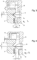
- the auxiliary guide member 14 In the properly guided position of the transport carriage Tn, that is, when the profile member 9 (or the profile members 9, 9 ') is arranged in the guide track 12 with a precise fit, the auxiliary guide member 14 preferably does not touch the auxiliary guide 15, but only comes with the auxiliary guide 15 in contact when the profile member 9 is already a little "off track", as in connection with 3 and 4 is shown schematically.
- the representation of the 3 and 4 conceptually corresponds essentially to that in Fig. 2 Embodiment of transport car Tn and holding structure 3 shown, only a relevant section of which is shown.
- a position is shown in which the profile element 9 is essentially centered in the guide track 12, ie the offset b is zero or (as shown) negligibly small, ie within the functionally predetermined tolerances.
- the auxiliary guide member 14 is spaced from the auxiliary guide 15 and "floats" without contact over the surface of the auxiliary guide 15, thereby avoiding friction effects.
- the profile element 9 can move out of the centered position due to gravity, as shown in FIG Fig. 4 is represented by the relatively large offset b.
- the auxiliary guide member 14 comes into contact with the auxiliary guide 15 and thereby prevents the profile member 9 from sliding further out of the guide track 12.
- the representation of the 3 and 4 is distorted for the sake of visibility and not shown to scale.
- the maximum distance a is usually very small, for example in the range of one millimeter or less. This ensures that the width s of the air gap 10 cannot become too large. Because of the oblique profiling of the guide track 12 or the profile member 9, not only the distance a between the auxiliary guide member 14 and the auxiliary guide 15 changes with the offset b, but also the width s of the air gap 10 between the guide surface 11 and the surface of the passive part 13, and thus also between that of the drive coil Sm and the drive magnet 4. In order to optimize the effect of the magnetic forces, it is advantageous to keep the width s of the air gap 10 as small as possible.
- a further auxiliary guide with corresponding auxiliary guide members can be provided in order to limit the movement of the transport vehicle Tn in the opposite direction of ascent (i.e. descending and ascending). This is particularly useful if the transport route does not only run in one plane, but if the route also has swiveling or twisting and / or inclines. In practice, this can be done by providing a further auxiliary guide member on the trolley Tn, which comes into contact with a second auxiliary guide arranged on the holding structure 3 of the auxiliary guide 15 in the climbing direction z opposite.
- the holding structure 3 and auxiliary guide member 14 can be designed such that they are in contact as standard and the profile member 9 is thus centered or positioned in the guide track 12 essentially in a positively guided manner.
- the auxiliary guide 15 can only be in the area of the switches, or the divergence or convergence areas of the transport route be provided, for example by the holding structure 3 having raised surface or rail areas in these areas, with which the auxiliary guide member 14 comes into contact there.
- a profile element 9 and / or a running element 8 can be designed as a combined sliding / rolling element, the axis of rotation of which is arranged centrally (ie in the xz plane parallel to the z axis) in the passive part 13, the profiles or Projecting rolling surfaces from the passive part 13 on both sides.
- the profile member 9 and the running member 8 roll in single comb areas, where the rollers are pressed firmly against the guide surface 11 or into the guide track 12 by the magnetic force, so that the organs then act as rollers.
- double-comb areas where the contact pressure is minimal on both sides and the same roller is arranged on each side in a guide track 12, 12 ', it acts as a sliding element on both sides.
- Such an embodiment allows a very thin design of the passive part 13, which can be designed, for example, in a simple plate shape. Due to the slim shape, it is also easily possible to connect several individual transport vehicles arranged one behind the other in an articulated manner, so that they form a "train configuration" which is then moved together as a transport unit.
- the holding structures 3 can each have one or more guide tracks 12.
- the guide tracks 12 can be arranged symmetrically or asymmetrically, that is to say the guide tracks 12 can be of the same or different design on the two sides.
- Asymmetrical arrangements offer the advantage that the orientation of the transport vehicle Tn is clearly defined, whereas symmetrical arrangements offer the advantage that symmetrically designed transport vehicles Tn can be attached to the holding structure 3 on both sides without the operator having to pay attention to the orientation.
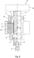
- Fig. 5 shows a transport vehicle Tn arranged on a long stator linear motor 1 according to a further exemplary embodiment.
- the passive part 13 of the in Fig. 5 shown transport vehicle Tn is designed as a relatively slender plate body.
- the profile element 9 and the running element 8 are designed as combined sliding / rolling elements, the axis of rotation of which is centered (ie in the xz plane parallel to the z-axis) are arranged in the passive part 13, the profile of the profile member 9 and the rolling surface of the running member 8 each protruding from the passive part 13 on both sides.
- the profile member 9 and the running member 8 are arranged in slots or passages that cross the passive part 13 in the transverse direction.
- Permanent magnets are arranged as drive magnets 4 on the side of the plate-shaped passive part 13.
- the auxiliary guide member 14 is in turn designed as a roller body with an axis of rotation parallel to the transverse axis, in which case only one auxiliary guide member 14 on (in Fig. 5 ) the lower end of the passive part is arranged in a corresponding receptacle. In the "normal" position (ie when the profile member 9 is centered in the guide track 12), the auxiliary guide member 14 can in turn be spaced apart from the auxiliary guide 15, or it can be essentially in constant contact with this auxiliary guide 15.
- the holding structure 3 consists of several separate units, which are designated 3a, 3b and 3c.
- the guide track 12 is provided in a guide rail 3b and the running element 8 rolls or slides along a guide track 3c.
- the auxiliary guide 15 is also designed as a separate unit.
- the part of the holding structure designated 3a only contains the drive coils and is otherwise not in direct mechanical contact with the transport trolley. This version makes maintenance and replacement of worn or defective parts easier.
- the holding structure 3a, 3b, 3c can be arranged on one side or on both sides.
Landscapes
- Engineering & Computer Science (AREA)
- Physics & Mathematics (AREA)
- Electromagnetism (AREA)
- Power Engineering (AREA)
- Mechanical Engineering (AREA)
- Chemical & Material Sciences (AREA)
- Combustion & Propulsion (AREA)
- Transportation (AREA)
- Linear Motors (AREA)
- Non-Mechanical Conveyors (AREA)
Priority Applications (6)
| Application Number | Priority Date | Filing Date | Title |
|---|---|---|---|
| EP18184227.9A EP3597471A1 (fr) | 2018-07-18 | 2018-07-18 | Moteur linéaire à stator long |
| JP2019110032A JP2020011845A (ja) | 2018-07-18 | 2019-06-13 | 長固定子リニアモータ |
| KR1020190083554A KR20200010054A (ko) | 2018-07-18 | 2019-07-11 | 롱-스테이터 선형 모터 |
| CA3049441A CA3049441A1 (fr) | 2018-07-18 | 2019-07-12 | Moteur lineaire a long stator |
| CN201910638051.XA CN110733898A (zh) | 2018-07-18 | 2019-07-16 | 长定子直线电机 |
| US16/514,189 US10923997B2 (en) | 2018-07-18 | 2019-07-17 | Long-stator linear motor |
Applications Claiming Priority (1)
| Application Number | Priority Date | Filing Date | Title |
|---|---|---|---|
| EP18184227.9A EP3597471A1 (fr) | 2018-07-18 | 2018-07-18 | Moteur linéaire à stator long |
Publications (1)
| Publication Number | Publication Date |
|---|---|
| EP3597471A1 true EP3597471A1 (fr) | 2020-01-22 |
Family
ID=62985975
Family Applications (1)
| Application Number | Title | Priority Date | Filing Date |
|---|---|---|---|
| EP18184227.9A Withdrawn EP3597471A1 (fr) | 2018-07-18 | 2018-07-18 | Moteur linéaire à stator long |
Country Status (6)
| Country | Link |
|---|---|
| US (1) | US10923997B2 (fr) |
| EP (1) | EP3597471A1 (fr) |
| JP (1) | JP2020011845A (fr) |
| KR (1) | KR20200010054A (fr) |
| CN (1) | CN110733898A (fr) |
| CA (1) | CA3049441A1 (fr) |
Families Citing this family (16)
| Publication number | Priority date | Publication date | Assignee | Title |
|---|---|---|---|---|
| EP4199344A1 (fr) * | 2017-09-14 | 2023-06-21 | B&R Industrial Automation GmbH | Moteur linéaire à stator long |
| DE102018209722A1 (de) * | 2018-06-15 | 2019-12-19 | Krones Ag | Vorrichtung zur Unterstützung von Transportelementen an Linearmotoren |
| DE102018209727A1 (de) * | 2018-06-15 | 2019-12-19 | Krones Ag | Mover für eine Transportvorrichtung |
| EP4061752B1 (fr) * | 2019-11-22 | 2025-03-12 | Abb Schweiz Ag | Transporteur, système de transport et procédé de fabrication de transporteur |
| CN111585417B (zh) * | 2020-05-28 | 2021-07-30 | 歌尔股份有限公司 | 直线电机 |
| CN111564941B (zh) * | 2020-06-15 | 2021-07-20 | 中车株洲电机有限公司 | 一种直线电机长定子电缆绕组端部弯形装置及其方法 |
| CN113353647B (zh) * | 2021-06-30 | 2022-06-24 | 安徽华宏机械设备有限公司 | 一种给料均匀的双螺杆计量给料装置 |
| EP4125192B1 (fr) * | 2021-07-28 | 2024-10-02 | Schneider Electric Industries SAS | Système de moteur linéaire, palier et procédé de fonctionnement d'un tel système |
| CA3248182A1 (fr) | 2022-04-13 | 2023-10-19 | Aprecia Pharmaceuticals LLC | Système et procédé de fabrication additive à l’aide d’un appareil de déplacement magnétique omnidirectionnel |
| EP4339140A1 (fr) * | 2022-09-14 | 2024-03-20 | Siemens Aktiengesellschaft | Agencement, aiguillage, procédé, système informatique, produit de programme informatique |
| US12103402B2 (en) | 2022-09-14 | 2024-10-01 | Rockwell Automation Technologies, Inc. | System and method for controlling direction of a vehicle in an independent cart system |
| DE112022007164T5 (de) | 2022-11-07 | 2025-05-15 | Mitsubishi Electric Corporation | Lineare Transportvorrichtung |
| CN116061698B (zh) * | 2023-04-06 | 2023-06-09 | 成都西交华创科技有限公司 | 一种兼容既有铁路的高温超导磁悬浮系统及改造方法 |
| US12121936B1 (en) | 2023-05-31 | 2024-10-22 | General Mills, Inc. | Processing system for handling pieces of product |
| US12545506B2 (en) | 2023-12-11 | 2026-02-10 | Rockwell Automation Technologies, Inc. | System for zero radius direction change in an independent cart system |
| WO2026051976A1 (fr) * | 2024-09-06 | 2026-03-12 | 果栗智造(上海)技术股份有限公司 | Ligne de transport |
Citations (5)
| Publication number | Priority date | Publication date | Assignee | Title |
|---|---|---|---|---|
| US20130074724A1 (en) * | 2009-01-23 | 2013-03-28 | Magnemotion, Inc. | Transport system powered by short block linear synchronous motors and switching mechanism |
| US20150027860A1 (en) * | 2013-07-29 | 2015-01-29 | Ats Automation Tooling Systems Inc. | Conveyor bearing system |
| EP3109998A1 (fr) * | 2015-06-23 | 2016-12-28 | Bernecker+Rainer Industrie-Elektronik Gesellschaft MbH | Procede et moteur lineaire a stator long destine a transferer une unite de transport a une position de transmission |
| EP3457560A1 (fr) * | 2017-09-14 | 2019-03-20 | B&R Industrial Automation GmbH | Moteur linéaire à stator long |
| EP3458390A1 (fr) * | 2017-03-06 | 2019-03-27 | ATS Automation Tooling Systems Inc. | Système convoyeur à moteur linéaire avec dérouteur et procédé de conception et de configuration de celui-ci |
Family Cites Families (7)
| Publication number | Priority date | Publication date | Assignee | Title |
|---|---|---|---|---|
| KR101748447B1 (ko) * | 2009-01-23 | 2017-06-16 | 마그네모션, 인코포레이티드 | 쇼트블록 리니어 싱크로너스 모터 및 스위칭 메카니즘에 의해 작동되는 향상된 운송 시스템 |
| US8616134B2 (en) * | 2009-01-23 | 2013-12-31 | Magnemotion, Inc. | Transport system powered by short block linear synchronous motors |
| DE102014214107A1 (de) * | 2013-08-26 | 2015-02-26 | Robert Bosch Gmbh | Transportvorrichtung |
| CN105813886B (zh) * | 2013-09-21 | 2018-04-03 | 麦克纳莫绅有限公司 | 用于包装和其它用途的线性电机运输 |
| CN106416027B (zh) * | 2014-06-02 | 2019-11-01 | Ats自动化加工系统公司 | 具有动力曲线轨道区段的线性马达系统 |
| WO2018145214A1 (fr) * | 2017-02-13 | 2018-08-16 | Ats Automation Tooling Systems Inc. | Système de transporteur à moteur linéaire et éléments mobiles pour celui-ci fournissant un pas d'outillage réduit |
| EP3489072B1 (fr) * | 2017-11-24 | 2022-01-19 | B&R Industrial Automation GmbH | Trajet de transport d'un moteur linéaire à stator long |
-
2018
- 2018-07-18 EP EP18184227.9A patent/EP3597471A1/fr not_active Withdrawn
-
2019
- 2019-06-13 JP JP2019110032A patent/JP2020011845A/ja active Pending
- 2019-07-11 KR KR1020190083554A patent/KR20200010054A/ko not_active Withdrawn
- 2019-07-12 CA CA3049441A patent/CA3049441A1/fr not_active Abandoned
- 2019-07-16 CN CN201910638051.XA patent/CN110733898A/zh active Pending
- 2019-07-17 US US16/514,189 patent/US10923997B2/en not_active Expired - Fee Related
Patent Citations (6)
| Publication number | Priority date | Publication date | Assignee | Title |
|---|---|---|---|---|
| US20130074724A1 (en) * | 2009-01-23 | 2013-03-28 | Magnemotion, Inc. | Transport system powered by short block linear synchronous motors and switching mechanism |
| US20150027860A1 (en) * | 2013-07-29 | 2015-01-29 | Ats Automation Tooling Systems Inc. | Conveyor bearing system |
| US9428347B2 (en) | 2013-07-29 | 2016-08-30 | Ats Automation Tooling Systems Inc. | Conveyor bearing system |
| EP3109998A1 (fr) * | 2015-06-23 | 2016-12-28 | Bernecker+Rainer Industrie-Elektronik Gesellschaft MbH | Procede et moteur lineaire a stator long destine a transferer une unite de transport a une position de transmission |
| EP3458390A1 (fr) * | 2017-03-06 | 2019-03-27 | ATS Automation Tooling Systems Inc. | Système convoyeur à moteur linéaire avec dérouteur et procédé de conception et de configuration de celui-ci |
| EP3457560A1 (fr) * | 2017-09-14 | 2019-03-20 | B&R Industrial Automation GmbH | Moteur linéaire à stator long |
Also Published As
| Publication number | Publication date |
|---|---|
| CN110733898A (zh) | 2020-01-31 |
| US20200028427A1 (en) | 2020-01-23 |
| KR20200010054A (ko) | 2020-01-30 |
| JP2020011845A (ja) | 2020-01-23 |
| US10923997B2 (en) | 2021-02-16 |
| CA3049441A1 (fr) | 2020-01-18 |
Similar Documents
| Publication | Publication Date | Title |
|---|---|---|
| EP3597471A1 (fr) | Moteur linéaire à stator long | |
| EP3385110B1 (fr) | Procédé de réglage de la force normale d'une unité de transport d'un moteur linéaire à stator longs | |
| EP3457560A1 (fr) | Moteur linéaire à stator long | |
| EP3547530A1 (fr) | Procédé de fonctionnement d'un dispositif de transport en forme de moteur linéaire à stator long | |
| DE102017108572A1 (de) | Lineartransportsystem | |
| EP3820798B1 (fr) | Système de transport et appareil de transport | |
| EP3807196A1 (fr) | Dispositif de soutien d'éléments de transport sur des moteurs linéaires | |
| EP3489175B1 (fr) | Dispositif de transport sous forme d'un moteur linéaire à stator long doté d'une section de retournement | |
| DE102016210030A1 (de) | Schienentransportsystem und Schienenfahrzeug für ein Schienentransportsystem | |
| DE102007032546A1 (de) | Kettenglied für eine umlaufende Transportkette einer Werkzeugmaschine, sowie Doppelendprofiler mit aus solchen Kettengliedern gebildeten Führungsketten | |
| DE2711994A1 (de) | Spaltweitensteuerung bei mindestens teilweise magnetisch gehaltenen fahrzeugen | |
| WO2018234174A1 (fr) | Cabine d'ascenseur à guidage à rouleaux destinée à un système d'ascenseur | |
| DE102011080749B4 (de) | Profilschienenwagen, Profilschiene und Profilschienenführung | |
| EP3424136B1 (fr) | Agencement de montage d'un moteur linéaire pour ascenseur | |
| EP0859697A1 (fr) | Installation de transport actionnee par moteur lineaire | |
| EP3778446A1 (fr) | Dispositif de transport dans une installation de traitement destiné au traitement d'une pièce | |
| DE102015222678A1 (de) | Bewegungseinrichtung | |
| EP4359337B1 (fr) | Patin de guidage à galet permettant de guider une cabine d'ascenseur d'un ascenseur | |
| WO2024251537A1 (fr) | Système de transport | |
| DE2436106A1 (de) | Fahrtechnische einrichtung mit dauermagneten | |
| EP2958785A1 (fr) | Dispositif de transport et procédé permettant de faire fonctionner un tel dispositif de transport | |
| EP0759847A1 (fr) | Dispositif de transport pour une bande de materiau en mouvement, notamment dispositif d'etirage pour bandes de film plastique | |
| DE102023121400B3 (de) | Läufer für ein Transportsystem und Transportsystem | |
| DE9400343U1 (de) | Bodenfördersystem | |
| DE102018217958A1 (de) | Transportsystem zum Transport von Behältern entlang einer Transportbahn und Laufwagen |
Legal Events
| Date | Code | Title | Description |
|---|---|---|---|
| PUAI | Public reference made under article 153(3) epc to a published international application that has entered the european phase |
Free format text: ORIGINAL CODE: 0009012 |
|
| STAA | Information on the status of an ep patent application or granted ep patent |
Free format text: STATUS: THE APPLICATION HAS BEEN PUBLISHED |
|
| AK | Designated contracting states |
Kind code of ref document: A1 Designated state(s): AL AT BE BG CH CY CZ DE DK EE ES FI FR GB GR HR HU IE IS IT LI LT LU LV MC MK MT NL NO PL PT RO RS SE SI SK SM TR |
|
| AX | Request for extension of the european patent |
Extension state: BA ME |
|
| STAA | Information on the status of an ep patent application or granted ep patent |
Free format text: STATUS: REQUEST FOR EXAMINATION WAS MADE |
|
| 17P | Request for examination filed |
Effective date: 20200716 |
|
| RBV | Designated contracting states (corrected) |
Designated state(s): AL AT BE BG CH CY CZ DE DK EE ES FI FR GB GR HR HU IE IS IT LI LT LU LV MC MK MT NL NO PL PT RO RS SE SI SK SM TR |
|
| STAA | Information on the status of an ep patent application or granted ep patent |
Free format text: STATUS: EXAMINATION IS IN PROGRESS |
|
| 17Q | First examination report despatched |
Effective date: 20210604 |
|
| STAA | Information on the status of an ep patent application or granted ep patent |
Free format text: STATUS: THE APPLICATION IS DEEMED TO BE WITHDRAWN |
|
| 18D | Application deemed to be withdrawn |
Effective date: 20211015 |