EP3597480B1 - Véhicule utilitaire, de préférence un poids lourd, pourvu de carrosserie et de capteurs de mesure de poids - Google Patents
Véhicule utilitaire, de préférence un poids lourd, pourvu de carrosserie et de capteurs de mesure de poids Download PDFInfo
- Publication number
- EP3597480B1 EP3597480B1 EP19181909.3A EP19181909A EP3597480B1 EP 3597480 B1 EP3597480 B1 EP 3597480B1 EP 19181909 A EP19181909 A EP 19181909A EP 3597480 B1 EP3597480 B1 EP 3597480B1
- Authority
- EP
- European Patent Office
- Prior art keywords
- commercial vehicle
- loader
- vehicle
- weight measurement
- measurement sensors
- Prior art date
- Legal status (The legal status is an assumption and is not a legal conclusion. Google has not performed a legal analysis and makes no representation as to the accuracy of the status listed.)
- Active
Links
Images


Classifications
-
- G—PHYSICS
- G01—MEASURING; TESTING
- G01G—WEIGHING
- G01G19/00—Weighing apparatus or methods adapted for special purposes not provided for in the preceding groups
- G01G19/08—Weighing apparatus or methods adapted for special purposes not provided for in the preceding groups for incorporation in vehicles
-
- B—PERFORMING OPERATIONS; TRANSPORTING
- B60—VEHICLES IN GENERAL
- B60P—VEHICLES ADAPTED FOR LOAD TRANSPORTATION OR TO TRANSPORT, TO CARRY, OR TO COMPRISE SPECIAL LOADS OR OBJECTS
- B60P1/00—Vehicles predominantly for transporting loads and modified to facilitate loading, consolidating the load, or unloading
- B60P1/64—Vehicles predominantly for transporting loads and modified to facilitate loading, consolidating the load, or unloading the load supporting or containing element being readily removable
- B60P1/6418—Vehicles predominantly for transporting loads and modified to facilitate loading, consolidating the load, or unloading the load supporting or containing element being readily removable the load-transporting element being a container or similar
-
- B—PERFORMING OPERATIONS; TRANSPORTING
- B62—LAND VEHICLES FOR TRAVELLING OTHERWISE THAN ON RAILS
- B62D—MOTOR VEHICLES; TRAILERS
- B62D21/00—Understructures, i.e. chassis frame on which a vehicle body may be mounted
- B62D21/09—Means for mounting load bearing surfaces
-
- B—PERFORMING OPERATIONS; TRANSPORTING
- B62—LAND VEHICLES FOR TRAVELLING OTHERWISE THAN ON RAILS
- B62D—MOTOR VEHICLES; TRAILERS
- B62D33/00—Superstructures for load-carrying vehicles
- B62D33/04—Enclosed load compartments ; Frameworks for movable panels, tarpaulins or side curtains
Definitions
- the invention relates to a commercial vehicle, preferably a truck, with a body, a vehicle frame and weight measurement sensors.
- the DE 10 2011 080 245 A1 relates to a method for monitoring an additional load on a loading area of a vehicle, the method having a step of determining an additional load information of the additional load on the loading area by means of at least one weight signal.
- the weight signal represents a signal from a weight sensor arranged on the loading area.
- the DE 10 2016 219 176 A1 relates to a transport vehicle or a group of transport vehicles with a loading area and with at least one load detection unit which is designed to detect the weight of a load on the loading area.
- the object of the invention is to create an alternative and/or improved technique for measuring the weight of a commercial vehicle with a body.
- the utility vehicle is preferably a truck.
- the utility vehicle has a structure for loading cargo and a vehicle body frame (e.g., comprising at least two parallel vehicle rails or other structure that supports the body).
- a plurality of weight measurement sensors e.g. with an optical, electronic and/or mechanical operating principle
- the structure is subsequently placed on the vehicle main frame with the preassembled plurality of weight measurement sensors (eg on the weight measurement sensors).
- the utility vehicle has a display device.
- the display device is for displaying weight measurements load states of the different sections of the body determined by the plurality of weight measurement sensors and/or a center of gravity of a load of a load of the body determined by weight measurements of the plurality of weight measurement sensors and/or by axle loads of the commercial vehicle determined by weight measurements of the plurality of weight measurement sensors (e.g. the display device is correspondingly controlled by a processing unit for such a display).
- the commercial vehicle offers the possibility that the commercial vehicle with an identical structure with regard to the vehicle main frame and weight measuring sensors can be used for a large number of different superstructures.
- the commercial vehicle can be set up ready for operation by a commercial vehicle manufacturer, including the pre-assembled weight measurement sensors. After that, for example, a specialized body manufacturer can place any body desired by the customer on the vehicle main frame.
- Load states can be determined in several sections of a large number of different structures by measuring the pre-assembled weight measurement sensors. It is not necessary for the bodybuilder to develop his own load measurement system and adapt it for each body type.
- the weight measurement sensors can be integrated into the main vehicle frame and/or arranged on an upper side of the main vehicle frame. It is possible for the weight measurement sensors to be fixed to the main vehicle frame.
- the loading states and/or the center of gravity can preferably be determined by means of a processing unit.
- the processing unit can be in communication with the weight measurement sensors and/or the display device.
- a displayed size and/or number of areas can be set and/or changed by a user. For example, multiple areas can be merged for convenience, etc.
- the plurality of weight measurement sensors are body-independent on the vehicle's main frame for use with a variety of different bodies (e.g., including open bodies (e.g., dump and dump bodies) and/or closed bodies (e.g., box bodies) ) pre-assembled for subsequent attachment to the vehicle main frame.
- the structure consists of a group of a plurality of structures, preferably of different structure types, for example comprising at least one open structure (e.g. tipper or trough structure) and at least one closed structure (e.g. box structure), preferably wherein the plurality of structures is designed to be placed on the main vehicle frame and for use with the plurality of weight measurement sensors.
- the plurality of weight measuring sensors are arranged at connection points of the vehicle main frame to the body, preferably at least at four outer corner points of a connection to the body (e.g. front and rear; left and right, for example at at least six connection points (e.g. front, middle and rear; each left and right, optionally e.g. additionally in the middle).
- the utility vehicle has an electrical or electronic body interface in communication with the plurality of weight measurement sensors for providing the measurement signals of the plurality of weight measurement sensors by means of the electrical or electronic body interface (e.g. directly or indirectly (e.g. processed or forwarded, e.g. by processing unit)).
- the electrical or electronic body interface e.g. directly or indirectly (e.g. processed or forwarded, e.g. by processing unit)
- This enables the weight measurements or load states to be transmitted to a processing unit of the body and/or a display unit of the body.
- the body manufacturer can thus, for example, provide type-specific one or more loader display units on or in the body or vehicle, which can be viewed by a loader during a typical loading process according to the type of body.
- the body interface may be preassembled, for example by the manufacturer of the commercial vehicle, before the body is placed on the vehicle main frame, for example by the body manufacturer.
- the electrical or electronic body interface prefferably be arranged in a driver's cab of the commercial vehicle and/or on the vehicle main frame underneath the body.
- the display device has at least one loader display unit (e.g. permanently installed or mobile) which is arranged outside a driver's cab of the commercial vehicle, preferably visible to a loader loading the body.
- loader display unit e.g. permanently installed or mobile
- the at least one loader display unit is in communication with the body interface to receive the measurement signals from the plurality of weight measurement sensors (e.g. directly or indirectly (for example forwarded or processed by a processing unit)).
- a plurality of loader display units arranged in a distributed manner are provided, which preferably each display a loading status of an assigned section of the body and/or respective loading states of a plurality of assigned sections of the body. This can make it possible, for example, for at least one loader display unit to be provided for different loading processes and/or for at least one loader display unit to be visible to the loader depending on the position of the loader.
- a loader display unit which preferably displays the loading states of several or all sections of the body. This allows an overview of several or all sections of the structure to be provided in one place.
- the body is an enclosed body, preferably a box body and/or a canvas body with a fixed ceiling
- the at least one loader display unit is mounted (e.g., internally) on a ceiling (e.g., a rear portion of the Ceiling with respect to a forward direction of the commercial vehicle) (and / or z. B. on a side wall) of the structure arranged.
- a ceiling e.g., a rear portion of the Ceiling with respect to a forward direction of the commercial vehicle
- the loader display unit can still be viewed, for example, when the body is (almost) fully loaded.
- the body is an open body, preferably a tipper and/or a dump body, and the at least one loader display unit is arranged on both longitudinal outer sides of the body (e.g. a first loader display unit is on a first longitudinal outer side of the body and a second loader display unit is disposed on an opposite second longitudinal outside of the body).
- At least one loader display unit on a rear side of the body.
- a driver of an excavator or wheel loader can recognize the loading status of the body during loading and continue to load the body accordingly.
- the body is a tarpaulin-covered body, preferably a flatbed body with the tarpaulin, and the at least one loader display unit is arranged on ribs of the body and/or supporting elements of a body covering, preferably for viewing from both the inside and to be visible from the outside when the tarpaulin is folded up and/or removed.
- the structure is an open structure, preferably a flatbed structure and/or a platform structure, and the at least one loader display unit is arranged on a front wall of the structure and/or an outer rear wall of a driver's cab of the utility vehicle.
- the structure is an open, multi-storey structure, preferably a vehicle transporter structure, and the at least one loader display unit is arranged on the inside of structure parts and/or holders at eye level for the loader sitting in the vehicle to be loaded.
- the structure is a closed structure, preferably a tank and/or silo structure, and the at least one loader display unit is arranged on both longitudinal outer sides of the structure and/or at a filling opening of the structure.
- the at least one loader display unit is arranged (e.g. fastened) on the outside and/or visible from the outside of the utility vehicle, preferably the body.
- the display device has a preferably high-resolution driver's cab display unit arranged in a driver's cab of the utility vehicle.
- the display device preferably has both the at least one loader display unit and the driver's cab display unit.
- the display device may have a mobile display unit, for example a smartphone or a tablet computer.
- the utility vehicle has a processing unit which is designed to receive the measurement signals from the plurality of weight measurement sensors and to output output signals to the display device.
- the processing unit preferably compares the measurement signals with a predetermined and/or adjustable legally permissible limit and outputs a corresponding output signal (ie corresponding to a result of the comparison) from the display device.
- the processing unit also compares the measurement signals from the plurality of weight measurement sensors with a predetermined technically permissible limit value, which is higher than the legally permissible limit value, and outputs a corresponding output signal to the display device.
- the processing unit additionally compares the measurement signals from the plurality of weight measurement sensors with a further predetermined technically permissible limit value, which is higher than the technically permissible limit value, and outputs a corresponding output signal to the display device.
- the utility vehicle has a camera device which is arranged to record the different sections of the structure.
- Output signals are preferably output from the processing unit to the display device, for example, in such a way that the determined loading states of the different sections of the body are superimposed according to the different sections in a recording (e.g. real-time recording) of the camera device and/or the determined center of gravity is a recording ( e.g. real-time recording) is superimposed on the camera device.
- the load states determined are each represented by a combination of a number of illuminated symbols and a color of the illuminated symbols on the display device.
- display options on the display device have a representation of each section and together with previously initially determined unladen weights of the vehicle and the axle loads determined therefrom, each both as an absolute weight value and with color coding.
- a display with colored lights can be useful if, for example, the exact weight of the filling of the loading shovel cannot be determined when loading with a wheel loader.
- a limit value e.g. legally permissible limit value
- the commercial vehicle has a trailer and/or semi-trailer interface for receiving weight measurements of a load on a trailer or semi-trailer for display on the display device.
- the commercial vehicle has a communication interface for communicating with an external computer system, preferably a fleet management system, for transmitting the determined loading conditions and/or the determined center of gravity and/or the determined axle loads.
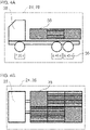
- FIGS. 1 and 2 show a commercial vehicle 10 configured as a truck.
- the commercial vehicle 10 has a main vehicle frame 12 , a driver's cab 14 and a body 16 .
- the main vehicle frame 12 is formed, for example, by two parallel longitudinal members which are connected to one another by a plurality of cross members.
- the vehicle main frame 12 extends in a longitudinal direction of the utility vehicle 10.
- the vehicle main frame 12 supports the driver's cab 14.
- the vehicle main frame 12 supports the body 16.
- the driver's cab 14 has a driver's workplace for a driver of the utility vehicle 10 .
- the driver's cab 14 is arranged in front of the body 16 in a longitudinal direction of the utility vehicle 10 .
- the driver's cab 14 can, for example, be mounted on the vehicle main frame 12 such that it can be tilted.
- the structure 16 is designed to accommodate cargo that is to be transported by the utility vehicle 10 .
- the structure 16 can be closed on all sides and, for example, have one or more doors for loading and unloading, e.g. B. Box body.
- the structure 16 can, for. B. also be open at the top for loading and unloading, z. B. trough body or tipper body.
- a plurality of weight measurement sensors 18 are already preinstalled on the main vehicle frame 12 before the assembly 16 is installed.
- the weight measurement sensors 18 are in particular pre-mounted on the vehicle main frame 12 independently of the structure, e.g. B. integrated into this.
- the weight sensors 18 can be used with a variety of different assemblies 16. This is relevant because the superstructures 16 are typically manufactured by specialized body manufacturers and are mounted without a body on a commercial vehicle 10 that has already been manufactured by a commercial vehicle manufacturer ready for operation.
- the weight measuring sensors 18 can be arranged on an upper side of the vehicle main frame 12, e.g. B. for arrangement at predetermined connection points to the structure 16. As shown, the weight measurement sensors can thus be arranged in principle between the vehicle main frame 12 and the structure 16.
- the plurality of weight measuring sensors 18 are distributed on the vehicle main frame 12 such that different sections of the body 16 can be monitored.
- weight measuring sensors 18 can be arranged at least at all four corners of the connection of the body 16, for example on longitudinal members or cross members of the vehicle main frame 12.
- a first weight measuring sensor 18 can be positioned at the front of, preferably on, a first longitudinal member of the commercial vehicle 10 with respect to a forward direction of travel of the commercial vehicle 10 Vehicle main frame 12 may be arranged.
- a second weight measuring sensor 18 can be arranged at the rear of, preferably on, the first side member with respect to the forward direction of travel.
- a third weight measuring sensor 18 can be arranged at the front, preferably on, a second longitudinal beam of the vehicle main frame 12 with respect to the forward direction of travel of the utility vehicle.
- a fourth weight measuring sensor 18 can be arranged at the rear of, preferably on, the second side member with respect to the forward direction of travel. It is also possible for the first and third weight measurement sensors 18 to be arranged at, preferably on, opposite ends of a front cross member of the vehicle main frame 12 and/or for the second and fourth weight measurement sensors 18 to be arranged at opposite ends of a rear cross member of the vehicle main frame. As shown, six weight measuring sensors 18, for example, can also be provided, preferably for measuring two front (left and right), two middle (left and right) and two rear (left and right) sections of the structure 16.
- the measurement accuracy can be increased by increasing the number of weight measurement sensors 18 and selecting the respective position of the additional weight measurement sensors 18 to match the connection points of the body 16 to the vehicle main frame 12, such as bridge attachment brackets.
- the weight measurement sensors 18 can carry out a weight force measurement on the structure 16 according to any known principle.
- the weight measurement sensors 18 can be embodied as pressure sensors, optical sensors, electronic sensors, and so on.
- the measurement by the weight measurement sensors 18 can be carried out with a reasonable accuracy, for example depending on the load, possibly also depending on the application with adjustable weight tolerance ranges.
- the weight measuring sensors 18 can output electrical signals that indicate a measured weight force, which can be displayed, for example, processed or unprocessed by a display device 24, 28.
- the weight measurement sensors 18 may be in communication with a processing unit 22 for transmitting the electrical signals.
- the processing unit 22 is, for example, initially calibrated with respect to the structure 16 in order to determine an empty weight of the structure 16 and permissible limits for the load weight in the structure 16 .
- information on the weights of commercial vehicle 10, body 16, axle load distribution (in the assembled state) etc. can be determined and stored in a corresponding memory of processing unit 22.
- the processing unit 22 can then access these values in its calculation logic for the loading conditions and the center of gravity.
- the processing unit 22 may determine the load conditions of the different monitored portions of the structure 16 based on the electrical signals from the weight measurement sensors 18 .
- the processing unit 22 may further determine a center of gravity of the load of the body 16 based on the electrical signals from the weight measurement sensors 18 .
- the processing unit 22 can, for example, control a driver's cab display unit 24 to display the load states of the different sections and/or the center of gravity of the body 16 . This allows a user in the cab, z. B. the driver of the commercial vehicle 10, about the loading status of each monitored section of the body 16 and the focus of the load are informed.
- the driver's cab display unit 24 can have, for example, a high-resolution display (for example an LCD display), preferably a secondary display in or on the center console, preferably outside of the instrument cluster behind a steering wheel in the driver's cab.
- a high-resolution display for example an LCD display
- secondary display in or on the center console, preferably outside of the instrument cluster behind a steering wheel in the driver's cab.
- the weight measurement sensors 18 may also be connected to an electronic body interface 26 directly or indirectly, for example via the processing unit 22 .
- the electronic body interface 26 can be provided by the manufacturer of the commercial vehicle 10 (without body) in order to provide a communication interface for the manufacturer of the body 16 via which the relevant data from the weight measuring sensors 18 can be called up.
- the electronic body interface 26 can be a standardized interface from the manufacturer. This means that 16 the information regarding the weight measurements of the weight measuring sensors 18 (for example loading conditions of the individual sections and/or the center of gravity of the loading of the structure 16) can be called up for further use. In particular, this allows the body manufacturer to arrange their own loader display units 28 on the commercial vehicle 10, preferably in or on the outside of the body 16. In this way, one or more loader display units 28 for informing loaders of the structure 16 can be provided in a structure-specific manner, ie depending on the type and size of the structure 16 .
- the loader display unit or units 28 are preferably arranged in such a way that they are clearly visible to the loader in accordance with the respective type and the respective size of the structure 16 when the respective structure 16 is loaded as intended.
- these can be distributed on the outside or in the structure 16 and can be provided redundantly, that is to say in each case designed in a similar or identical manner or displaying similar or identical information. This makes it possible, for example, for the loader to see directly during the loading process which weight has already been loaded, which weight can still be loaded and/or how the weight is distributed. By recognizing the distribution of the weight, it is also possible to continue loading in a targeted manner. In this way, the existing loading space in the body 16 can be used as effectively as possible and correct axle load distribution can be ensured.
- FIG. 1 and 2 show a trough or tipper body 16 .
- This body 16 is usually loaded from a longitudinal side of the body 16, for example by a wheel loader, an excavator, etc.
- the loader display units 28 can be arranged here, for example, on both longitudinal outer sides of the body 16 so that they are clearly visible to the driver of the wheel loader or excavator etc. from the outside while the body 16 is being loaded.
- the loader display units 28 may extend along substantially an entire length of the body 16 (as shown) or may be located on the longitudinal outer sides of the body 16 in only a portion, for example forward, center, or rear.
- An alternative or additional loader display unit can be arranged on a rear side of the superstructure 16, for example.
- the body 16 is formed as a box body, in which the loader display unit is arranged in particular in the body 16 on a ceiling of the body 16 . It is also possible alternative or to arrange additional display units inside or outside of the structure 16 on side walls, on the floor, on one or more doors of the structure 16.
- a mobile display unit can be provided in addition or as an alternative, which communicates, for example, wirelessly or with a cable with the processing unit 22 for displaying the measured loading states and/or the center of gravity.
- the mobile display unit can be in the form of a tablet computer or a smartphone.
- a user interface (not shown), e.g. B. for the driver and / or the loader is provided.
- the size and number of monitored areas can be changed via the user interface.
- separately monitored areas can be combined into a single area in certain use cases.
- the areas can be parameterized. Such settings can, for example, also be changeable or unchangeable by the body manufacturer himself.
- the display units 24, 28 are to be designed in such a way that they can be seen in any loading condition, day or night, even in direct sunlight.
- the weight measurement sensors 18 can carry out the weight measurements both when the motor vehicle is stationary and when it is moving.
- the display units 24, 28 can display the weight in the individual sections of the structure 16 and the center of gravity of the load in the structure 16, for example continuously at any time, both when stationary and while driving.
- a display while driving by the driver's cab display units 24 also makes it possible, for example, for undesired load displacements to be detected while driving, which can be caused, for example, by insufficient load securing.
- the commercial vehicle prefferably has an electronic trailer and/or semi-trailer interface 29 for receiving weight measurements of a load on a trailer or semi-trailer for display on the display unit 24 and/or 28 .
- a communication interface 31 can be provided for communication with an external computer system, preferably a fleet management system, for transmission of the ascertained loading states and/or the ascertained center of gravity.
- the loading information can be transmitted to a freight forwarder or vehicle operator will. This can, for example, identify potentially additional loading capacity at any time during a tour, etc.
- the display by the display units 24, 28 may include, for example, a graphic display of the entire vehicle with information on the actual individual weights of the load, the weight measuring sensors 18, or colored lights, or a combination thereof, as with reference to FIG Figures 3A to 4B is described.
- a camera device 30 (see figure 1 ) is arranged, for example, on the structure 16, which receives the structure 16, for example in real time.
- the camera device 30 may preferably be arranged to capture the various portions of the structure 16 associated with the weight measurement sensors 18 .
- the display units 24, 28 can superimpose the determined loading states and/or the determined center of gravity of a recording (e.g. real-time recording, for example a moving image) of the camera device 30.
- auxiliary lines for the loading sections to be superimposed on the recording and, for example, color information for the respective loading sections to be displayed. For example, colored illuminated symbols can be displayed for each loading area, or the loading areas can each be colored across the board, depending on the respective loading status.
- the center of gravity determined can be superimposed on the recording of the camera device 30 in a correct perspective.
- Figures 3A to 4B show different exemplary representations of a graphic display on the display unit 24 and/or 28.
- the display is here both in side view ( Figure 3A , 4A ) as well as in top view ( Figures 3B , 4B ) shown.
- a pictogram 32 that graphically represents the commercial vehicle 10 is displayed.
- a color display e.g. traffic light
- the number of color displays 34 can also be smaller or larger than the number shown here.
- alphanumeric displays 36 relating to the respective axle loads can also be displayed, which can be determined, for example, from the weight measurements of the weight measuring sensors 18, e.g. B. from the processing unit 22.
- the display can be made more detailed (not shown separately) by means of illuminated symbols which are assigned to the monitored areas. For example, a number of symbols that light up and their coloring can be used to display a load status in the assigned area in a way that the observer can understand.
- 1 green light between 0% and 20% of the legal load limit.
- 2 green lights charged between 20% and 40% of the legal limit.
- 3 green lights charged between 40% and 60% of the legal limit.
- 4 green lights charged between 60% and 80% of the legal limit.
- 4 green lights and 1 yellow light charged between 80% and 100% of the legal limit.
- 4 green lights and 1 yellow light and 1 red light charged between 100% and 115% of the legal limit and/or between 0% and 50% of the range between the legal and technical limits.
- 4 green lights and 1 yellow light and 2 red lights charged between 115% and 130% of the legal limit and/or between 50% and 100% of the range between the legal and technical limits.
- the background to this detailed display option may be that there is more than one limit to the payload for a commercial vehicle. Instead, for example, a legally permissible limit for operation on public roads, a technically permissible limit for operation on non-public roads and in some cases also a higher or further technically permissible limit with operating restrictions for the commercial vehicle 10, e.g. operation only at reduced vehicle speed, so that an adapted, differentiated display can be useful here and offers added value. In addition, with such a differentiated display there is also the possibility of recognizing how much has to be unloaded or reloaded if necessary in order not to exceed a target limit when loading.
- the legally permissible limit value(s), the technically permissible limit value(s) and the further or higher technically permissible limit value(s) can be stored, for example, in a memory of the processing unit 22 .
- the processing unit 22 can control the display units 24, 28 in accordance with one or more comparisons of the load states determined by the weight measurement sensors with the limit value(s).
- the monitored areas in the structure 16 can be shown as segments 38 in addition to the utility vehicle pictogram 32 .
- the segments 38 can be of different colors, e.g. red, yellow, green, colored according to the respective load status of the area or segment. Different hatching can correspond to different colors.
Landscapes
- Engineering & Computer Science (AREA)
- Physics & Mathematics (AREA)
- General Physics & Mathematics (AREA)
- Transportation (AREA)
- Mechanical Engineering (AREA)
- Component Parts Of Construction Machinery (AREA)
Claims (13)
- Véhicule utilitaire (10), de préférence poids lourd, comprenant :une structure (16) servant au chargement d'une cargaison ;un châssis principal de véhicule (12), sur lequel sont prémontés une pluralité de capteurs de mesure de poids (18) et sont arrangés répartis en vue de mesure le poids de différentes portions de la structure (16), la structure (16) étant posée ultérieurement sur le châssis principal de véhicule (12) pourvu de la pluralité de capteurs de mesure de poids (18) ; etun dispositif d'affichage (24, 28) destiné à afficher des états de chargement des différentes portions de la structure (16), déterminés par les mesures du poids de la pluralité de capteurs de mesure de poids (18), et/ou un centre de gravité de chargement d'un chargement de la structure (16), déterminé par les mesures du poids de la pluralité de capteurs de mesure de poids (18), et/ou des charges d'essieu du véhicule utilitaire (10), déterminées par les mesures du poids de la pluralité de capteurs de mesure de poids (18),le dispositif d'affichage (24, 28) possédant au moins une unité d'affichage de chargeur (28) qui est disposée endehors d'une cabine de conducteur (14) du véhicule utilitaire (10),caractérisé en ce que :l'au moins une unité d'affichage de chargeur (28) est disposée sur le véhicule utilitaire (10), de préférence la structure (16), à l'extérieur et/ou visible depuis l'extérieur ; etles états de chargement déterminés étant respectivement restitués par une combinaison d'un nombre de symboles lumineux s'allumant et une couleur des symboles lumineux qui s'allument sur le dispositif d'affichage (24, 28).
- Véhicule utilitaire (10) selon la revendication 1, la pluralité de capteurs de mesure de poids (18) étant prémontés indépendamment de la structure sur le châssis principal de véhicule (12) en vue d'une utilisation avec un grand nombre de structures différentes à poser ultérieurement sur le châssis principal de véhicule (12) ; et/ou
la structure (16) étant choisie à partir d'un groupe d'une pluralité de structures, de préférence de types de structure différents, comprenant par exemple une structure ouverte et au moins une structure fermée, la pluralité de structures étant configurées pour être posées sur le châssis principal de véhicule (12) et pour être utilisées avec la pluralité de capteurs de mesure de poids (18). - Véhicule utilitaire (10) selon la revendication 1 ou la revendication 2,
la pluralité de capteurs de mesure de poids (18) étant disposés au niveau de points d'attache du châssis principal de véhicule (12) avec la structure (16), de préférence au niveau d'au moins quatre sommets extérieurs d'une attache de la structure (16), par exemple au niveau d'au moins six points d'attache. - Véhicule utilitaire (10) selon l'une des revendications précédentes, comprenant en outre :
une interface de structure (26) électrique ou électronique en liaison de communication avec la pluralité de capteurs de mesure de poids (18) en vue de fournir les signaux de mesure de la pluralité de capteurs de mesure de poids (18) au moyen de l'interface de structure (26) électrique ou électronique. - Véhicule utilitaire (10) selon l'une des revendications précédentes,
l'au moins une unité d'affichage de chargeur (28) étant visible pour un chargeur qui charge la structure (16). - Véhicule utilitaire (10) selon la revendication 5, l'au moins une unité d'affichage de chargeur (28) étant en liaison de communication avec l'interface de structure (26) en vue de la réception des signaux de mesure de la pluralité de capteurs de mesure de poids (18).
- Véhicule utilitaire (10) selon la revendication 5 ou la revendication 6,plusieurs unités d'affichage de chargeur (28) disposées réparties étant présentes, lesquels affichent de préférence respectivement un état de chargement d'une portion associée de la structure (16) et/ou respectivement des états de chargement de plusieurs portions associées de la structure (16) ; ouune unité d'affichage de chargeur (28) étant présente, laquelle affiche de préférence les états de chargement de plusieurs ou de toutes les portions de la structure (16) .
- Véhicule utilitaire (10) selon l'une des revendications 5 à 7,la structure (16) étant une structure fermée, de préférence une structure en caisson et/ou une structure bâchée à enveloppe fixe, et l'au moins une unité d'affichage de chargeur (28) étant disposée au niveau d'une enveloppe de la structure (16) ; oula structure (16) étant une structure recouverte d'une bâche, de préférence une structure de carrosserie à plateforme comprenant la bâche, et l'au moins une unité d'affichage de chargeur (28) étant disposée au niveau d'arceaux de la structure et/ou d'éléments porteurs d'une couverture de structure, de préférence pour être visible depuis l'intérieur et, lorsque la bâche est relevée et/ou retirée, depuis l'extérieur ; oula structure (16) étant une structure ouverte, de préférence une structure de benne basculante et/ou de benne, et l'au moins une unité d'affichage de chargeur (28) étant disposée au niveau des deux côtés extérieurs longitudinaux de la structure (16) ; oula structure (16) étant une structure ouverte, de préférence une structure de carrosserie à plateforme et/ou une structure de plateforme, et l'au moins une unité d'affichage de chargeur (28) étant disposée au niveau d'une paroi frontale de structure de la structure (16) et/ou d'une paroi arrière de structure d'une cabine de conducteur (14) du véhicule utilitaire (10) ; oula structure (16) étant une structure ouverte à plusieurs étages, de préférence une structure de transporteur de véhicules, et l'au moins une unité d'affichage de chargeur (28) étant disposée pour chaque étage à l'intérieur au niveau de parties de structure et/ou d'éléments de maintien à hauteur des yeux du chargeur assis dans le véhicule à charger ; oula structure (16) étant une structure fermée, de préférence une structure de citerne et/ou de silo, et l'au moins une unité d'affichage de chargeur (28) étant disposée au niveau des deux côtés extérieurs longitudinaux de la structure (16) et/ou au niveau dune ouverture de remplissage de la structure.
- Véhicule utilitaire (10) selon l'une des revendications précédentes,
le dispositif d'affichage (24, 28) possédant une unité d'affichage de cabine de conducteur (24), de préférence à haute résolution, disposée dans une cabine de conducteur (14) du véhicule utilitaire (10), et de préférence :
le dispositif d'affichage (24, 28) possédant à la fois l'au moins une unité d'affichage de chargeur (28) et l'unité d'affichage de cabine de conducteur (24). - Véhicule utilitaire (10) selon l'une des revendications précédentes, comprenant en outre :
une unité de traitement (22), laquelle est configurée pour la réception des signaux de mesure en provenance de la pluralité de capteurs de mesure de poids (18) et pour délivrer des signaux de sortie au dispositif d'affichage (24, 28), l'unité de traitement (22) comparant les signaux de mesure avec une valeur limite prédéterminée autorisée par la loi et délivrant un signal de sortie correspondant au dispositif d'affichage (24, 28). - Véhicule utilitaire (10) selon la revendication 10, l'unité de traitement (22) comparant les signaux de mesure en provenance de la pluralité de capteurs de mesure de poids (18) avec une valeur limite prédéterminée techniquement admissible, laquelle est supérieure à la valeur limite prédéterminée autorisée par la loi, et délivrant un signal de sortie correspondant au dispositif d'affichage (24, 28), et de préférence :
l'unité de traitement (22) comparant les signaux de mesure en provenance de la pluralité de capteurs de mesure de poids (18) en plus avec une valeur limite prédéterminée techniquement admissible supplémentaire, laquelle est supérieure à la valeur limite prédéterminée autorisée par la loi, et délivrant un signal de sortie correspondant au dispositif d'affichage (24, 28). - Véhicule utilitaire (10) selon l'une des revendications précédentes, comprenant en outre :un arrangement de caméra (30), qui est disposé de manière à enregistrer les différentes portions de la structure (16) ;le dispositif d'affichage (24, 28) superposant les états de chargement déterminés des différentes portions de la structure (16) en correspondance avec les différentes portions dans un enregistrement de l'arrangement de caméra (30) et/ou superposant le centre de gravité déterminé à un enregistrement de l'arrangement de caméra (30) .
- Véhicule utilitaire (10) selon l'une des revendications précédentes, comprenant en outre :une interface de remorque et/ou de semi-remorque (29) destinée à recevoir des mesures de poids d'un chargement d'une remorque ou d'une semi-remorque en vue de l'affichage sur le dispositif d'affichage (24, 28) ; et/ouune interface de communication (31) destinée à la communication avec un système informatique externe, de préférence un système de gestion de flotte, en vue de transmettre les états de chargement déterminés et/ou le centre de gravité déterminé et/ou les charges d'essieu déterminées.
Priority Applications (1)
| Application Number | Priority Date | Filing Date | Title |
|---|---|---|---|
| EP22201329.4A EP4137361B1 (fr) | 2018-07-18 | 2019-06-24 | Véhicule utilitaire, de préférence camion, doté d'une structure et de capteurs de mesure de poids |
Applications Claiming Priority (1)
| Application Number | Priority Date | Filing Date | Title |
|---|---|---|---|
| DE102018117352.0A DE102018117352A1 (de) | 2018-07-18 | 2018-07-18 | Nutzfahrzeug, vorzugsweise Lastkraftwagen, mit Aufbau und Gewichtsmesssensoren |
Related Child Applications (2)
| Application Number | Title | Priority Date | Filing Date |
|---|---|---|---|
| EP22201329.4A Division EP4137361B1 (fr) | 2018-07-18 | 2019-06-24 | Véhicule utilitaire, de préférence camion, doté d'une structure et de capteurs de mesure de poids |
| EP22201329.4A Division-Into EP4137361B1 (fr) | 2018-07-18 | 2019-06-24 | Véhicule utilitaire, de préférence camion, doté d'une structure et de capteurs de mesure de poids |
Publications (2)
| Publication Number | Publication Date |
|---|---|
| EP3597480A1 EP3597480A1 (fr) | 2020-01-22 |
| EP3597480B1 true EP3597480B1 (fr) | 2022-12-07 |
Family
ID=67003243
Family Applications (2)
| Application Number | Title | Priority Date | Filing Date |
|---|---|---|---|
| EP19181909.3A Active EP3597480B1 (fr) | 2018-07-18 | 2019-06-24 | Véhicule utilitaire, de préférence un poids lourd, pourvu de carrosserie et de capteurs de mesure de poids |
| EP22201329.4A Active EP4137361B1 (fr) | 2018-07-18 | 2019-06-24 | Véhicule utilitaire, de préférence camion, doté d'une structure et de capteurs de mesure de poids |
Family Applications After (1)
| Application Number | Title | Priority Date | Filing Date |
|---|---|---|---|
| EP22201329.4A Active EP4137361B1 (fr) | 2018-07-18 | 2019-06-24 | Véhicule utilitaire, de préférence camion, doté d'une structure et de capteurs de mesure de poids |
Country Status (2)
| Country | Link |
|---|---|
| EP (2) | EP3597480B1 (fr) |
| DE (1) | DE102018117352A1 (fr) |
Cited By (1)
| Publication number | Priority date | Publication date | Assignee | Title |
|---|---|---|---|---|
| US20240094044A1 (en) * | 2022-09-16 | 2024-03-21 | Preston Medure | Vehicle weight monitoring system |
Families Citing this family (6)
| Publication number | Priority date | Publication date | Assignee | Title |
|---|---|---|---|---|
| DE102020209530A1 (de) | 2020-07-29 | 2022-02-03 | Ford Global Technologies, Llc | Lagersystem für einen Laderaum eines Nutzkraftwagens und Verfahren zum Überwachen einer Stückzahl und/oder eines Volumens eines in einer Aufnahmeeinheit in einem Nutzkraftwagen befindlichen Guts |
| DE102021133763A1 (de) | 2021-12-17 | 2023-06-22 | Zf Cv Systems Global Gmbh | Verfahren zur Ladungsüberwachung eines Fahrzeuggespanns |
| JP7647637B2 (ja) * | 2022-03-14 | 2025-03-18 | トヨタ自動車株式会社 | 車両、運動マネージャ、および、運動要求補正方法 |
| US20240017696A1 (en) * | 2022-05-25 | 2024-01-18 | Tusimple, Inc. | Chain of custody provenance for an autonomous vehicle |
| DE102023116806A1 (de) | 2023-06-27 | 2023-09-07 | Daimler Truck AG | Nutzfahrzeuggespann |
| DE102023210241A1 (de) | 2023-10-18 | 2025-04-24 | Robert Bosch Gesellschaft mit beschränkter Haftung | Verfahren zur Erfassung einer auf einer Ladefläche eines Fahrzeugs angeordneten Ladung, drucksensitives Sensorelement und Fahrzeug |
Family Cites Families (11)
| Publication number | Priority date | Publication date | Assignee | Title |
|---|---|---|---|---|
| GB2043921A (en) * | 1979-02-20 | 1980-10-08 | Edbro Holdings | Vehicle Load Monitor |
| WO1992006357A1 (fr) * | 1990-10-08 | 1992-04-16 | Wirth Gallo Messtechnik Ag | Dispositif de mesure de la charge |
| DE19508239A1 (de) * | 1995-03-08 | 1996-09-12 | Siemens Ag | LKW-Auflieger-Wiegeeinrichtung |
| DE20006480U1 (de) * | 2000-04-07 | 2000-10-05 | Faun Umwelttechnik GmbH & Co., 86167 Augsburg | Lastwagen |
| DE10334708A1 (de) * | 2003-07-30 | 2005-02-24 | Daimlerchrysler Ag | Nutzfahrzeug zum Stückguttransport |
| DE10341132A1 (de) * | 2003-09-06 | 2005-03-31 | Daimlerchrysler Ag | Beladungsanzeige eines Fahrzeuges |
| AT7633U1 (de) * | 2004-02-24 | 2005-06-27 | Krickl Herbert | Wägesystem zum wiegen der ladung eines fahrzeugs |
| DE202006018149U1 (de) * | 2006-11-28 | 2007-04-19 | Claas Saulgau Gmbh | Landwirtschaftliches Transportfahrzeug |
| DE202007002646U1 (de) | 2007-02-23 | 2007-05-03 | Schulze, Christian | Waage für Frachtgut, Ladegut, Nutzlast u.dgl., eingebaut in Fahrzeugen, wie z.B. Kraftfahrzeuge, Pkw, Busse, Lkw, insbesondere Nutzfahrzeuge mit / ohne Anhänger u.dgl. |
| DE102011080245A1 (de) | 2011-08-02 | 2013-02-07 | Robert Bosch Gmbh | Verfahren und Steuergerät zur Überwachung einer Zuladung auf einer Ladefläche eines Fahrzeugs, Sensorsystem und Fahrzeug mit Sensorsystem |
| DE102016219176B4 (de) * | 2016-10-04 | 2025-09-25 | Contitech Vibration Control Gmbh | Transportfahrzeug oder Transportfahrzeugverbund |
-
2018
- 2018-07-18 DE DE102018117352.0A patent/DE102018117352A1/de not_active Withdrawn
-
2019
- 2019-06-24 EP EP19181909.3A patent/EP3597480B1/fr active Active
- 2019-06-24 EP EP22201329.4A patent/EP4137361B1/fr active Active
Cited By (1)
| Publication number | Priority date | Publication date | Assignee | Title |
|---|---|---|---|---|
| US20240094044A1 (en) * | 2022-09-16 | 2024-03-21 | Preston Medure | Vehicle weight monitoring system |
Also Published As
| Publication number | Publication date |
|---|---|
| EP4137361B1 (fr) | 2024-10-30 |
| EP4137361A1 (fr) | 2023-02-22 |
| EP3597480A1 (fr) | 2020-01-22 |
| DE102018117352A1 (de) | 2020-01-23 |
Similar Documents
| Publication | Publication Date | Title |
|---|---|---|
| EP3597480B1 (fr) | Véhicule utilitaire, de préférence un poids lourd, pourvu de carrosserie et de capteurs de mesure de poids | |
| EP3689698B1 (fr) | Remorqueur | |
| DE102019105408A1 (de) | Grafiken zum rückwärts führen von anhängern | |
| DE102008000606A1 (de) | Fahrzeuganzeigeinstrumentsystem und Verfahren, dieses zu steuern | |
| EP2787330B1 (fr) | Système de pesage et procédé destiné à peser un chargement d'un train routier basculant | |
| DE102017201040A1 (de) | Verfahren und Einrichtung zur Identifikation einer Anbauvorrichtung | |
| DE102013206345A1 (de) | Anzeigevorrichtung und Verfahren zum Anzeigen von Daten und Fahrerassistenzsystem für ein Fahrzeug | |
| DE102016109954A1 (de) | Verfahren zum Unterstützen eines Fahrers eines Gespanns beim Rangieren des Gespanns, Fahrerassistenzsystem sowie Kraftfahrzeug | |
| DE202020104598U1 (de) | Nutzlastausgleichsindikator | |
| EP3482975A1 (fr) | Véhicule à chenille | |
| EP3597490A1 (fr) | Procédé de surveillance de l'état de chargement des véhicules utilitaires ou caisses mobiles pour véhicules utilitaires | |
| DE102016109425A1 (de) | Messmodul mit Kraft- und Beschleunigungssensoren zur Gewichtsermittlung eines an ein Zugfahrzeug gekoppelten Anhängefahrzeuges | |
| DE102011052218A1 (de) | Anhänger zur Verkehrsüberwachung | |
| DE102014216076A1 (de) | Vorrichtung und Verfahren zur Anzeige einer Ladungsverteilung in einem Kraftfahrzeug | |
| DE102020207838A1 (de) | System zur Erfassung einer Windsituation auf einer Fahrstrecke | |
| DE102011088071A1 (de) | Vorrichtung zum Melden einer Belastungsanomalie eines Kippwagens | |
| DE102009002117A1 (de) | Generieren einer Routenempfehlung | |
| DE102013012314B4 (de) | Verwendung einer fahrzeugfesten Bilderfassungs- und Analysevorrichtung zur Erfassung einer Beladungshöhe einer Beladung des Fahrzeugs | |
| WO2007112718A1 (fr) | module de pesage pour chargeuse à roues | |
| DE102022123359A1 (de) | Verfahren zum Kuppeln einer Sattelzugmaschine mit einem Sattelauflieger sowie Sattelzug mit einer Sattelzugmaschine und einem Sattelauflieger | |
| DE102015202696A1 (de) | Verfahren und Vorrichtung zum Bestimmen eines Ladungsgewichts eines Fahrzeugs | |
| DE102020123221A1 (de) | Verfahren zum Ermitteln und Überwachen eines Beladungszustandes von Kraftfahrzeugen auf Verkehrswegen | |
| DE102024121089A1 (de) | Fahrzeugüberwachungsgerät und -verfahren | |
| EP4323261B1 (fr) | Pivot d'attelage de sellette pour la semi-remorque d'un camion semi-remorque | |
| EP2492164A2 (fr) | Chariot de manutention, en particulier remorque |
Legal Events
| Date | Code | Title | Description |
|---|---|---|---|
| PUAI | Public reference made under article 153(3) epc to a published international application that has entered the european phase |
Free format text: ORIGINAL CODE: 0009012 |
|
| STAA | Information on the status of an ep patent application or granted ep patent |
Free format text: STATUS: THE APPLICATION HAS BEEN PUBLISHED |
|
| AK | Designated contracting states |
Kind code of ref document: A1 Designated state(s): AL AT BE BG CH CY CZ DE DK EE ES FI FR GB GR HR HU IE IS IT LI LT LU LV MC MK MT NL NO PL PT RO RS SE SI SK SM TR |
|
| AX | Request for extension of the european patent |
Extension state: BA ME |
|
| STAA | Information on the status of an ep patent application or granted ep patent |
Free format text: STATUS: REQUEST FOR EXAMINATION WAS MADE |
|
| 17P | Request for examination filed |
Effective date: 20200717 |
|
| RBV | Designated contracting states (corrected) |
Designated state(s): AL AT BE BG CH CY CZ DE DK EE ES FI FR GB GR HR HU IE IS IT LI LT LU LV MC MK MT NL NO PL PT RO RS SE SI SK SM TR |
|
| STAA | Information on the status of an ep patent application or granted ep patent |
Free format text: STATUS: EXAMINATION IS IN PROGRESS |
|
| 17Q | First examination report despatched |
Effective date: 20201202 |
|
| GRAP | Despatch of communication of intention to grant a patent |
Free format text: ORIGINAL CODE: EPIDOSNIGR1 |
|
| STAA | Information on the status of an ep patent application or granted ep patent |
Free format text: STATUS: GRANT OF PATENT IS INTENDED |
|
| INTG | Intention to grant announced |
Effective date: 20220722 |
|
| GRAS | Grant fee paid |
Free format text: ORIGINAL CODE: EPIDOSNIGR3 |
|
| GRAA | (expected) grant |
Free format text: ORIGINAL CODE: 0009210 |
|
| STAA | Information on the status of an ep patent application or granted ep patent |
Free format text: STATUS: THE PATENT HAS BEEN GRANTED |
|
| AK | Designated contracting states |
Kind code of ref document: B1 Designated state(s): AL AT BE BG CH CY CZ DE DK EE ES FI FR GB GR HR HU IE IS IT LI LT LU LV MC MK MT NL NO PL PT RO RS SE SI SK SM TR |
|
| REG | Reference to a national code |
Ref country code: GB Ref legal event code: FG4D Free format text: NOT ENGLISH |
|
| REG | Reference to a national code |
Ref country code: CH Ref legal event code: EP Ref country code: AT Ref legal event code: REF Ref document number: 1536124 Country of ref document: AT Kind code of ref document: T Effective date: 20221215 |
|
| REG | Reference to a national code |
Ref country code: DE Ref legal event code: R096 Ref document number: 502019006463 Country of ref document: DE |
|
| REG | Reference to a national code |
Ref country code: IE Ref legal event code: FG4D Free format text: LANGUAGE OF EP DOCUMENT: GERMAN |
|
| REG | Reference to a national code |
Ref country code: NL Ref legal event code: FP |
|
| REG | Reference to a national code |
Ref country code: SE Ref legal event code: TRGR |
|
| REG | Reference to a national code |
Ref country code: LT Ref legal event code: MG9D |
|
| PG25 | Lapsed in a contracting state [announced via postgrant information from national office to epo] |
Ref country code: NO Free format text: LAPSE BECAUSE OF FAILURE TO SUBMIT A TRANSLATION OF THE DESCRIPTION OR TO PAY THE FEE WITHIN THE PRESCRIBED TIME-LIMIT Effective date: 20230307 Ref country code: LT Free format text: LAPSE BECAUSE OF FAILURE TO SUBMIT A TRANSLATION OF THE DESCRIPTION OR TO PAY THE FEE WITHIN THE PRESCRIBED TIME-LIMIT Effective date: 20221207 Ref country code: FI Free format text: LAPSE BECAUSE OF FAILURE TO SUBMIT A TRANSLATION OF THE DESCRIPTION OR TO PAY THE FEE WITHIN THE PRESCRIBED TIME-LIMIT Effective date: 20221207 Ref country code: ES Free format text: LAPSE BECAUSE OF FAILURE TO SUBMIT A TRANSLATION OF THE DESCRIPTION OR TO PAY THE FEE WITHIN THE PRESCRIBED TIME-LIMIT Effective date: 20221207 |
|
| PG25 | Lapsed in a contracting state [announced via postgrant information from national office to epo] |
Ref country code: RS Free format text: LAPSE BECAUSE OF FAILURE TO SUBMIT A TRANSLATION OF THE DESCRIPTION OR TO PAY THE FEE WITHIN THE PRESCRIBED TIME-LIMIT Effective date: 20221207 Ref country code: PL Free format text: LAPSE BECAUSE OF FAILURE TO SUBMIT A TRANSLATION OF THE DESCRIPTION OR TO PAY THE FEE WITHIN THE PRESCRIBED TIME-LIMIT Effective date: 20221207 Ref country code: LV Free format text: LAPSE BECAUSE OF FAILURE TO SUBMIT A TRANSLATION OF THE DESCRIPTION OR TO PAY THE FEE WITHIN THE PRESCRIBED TIME-LIMIT Effective date: 20221207 Ref country code: HR Free format text: LAPSE BECAUSE OF FAILURE TO SUBMIT A TRANSLATION OF THE DESCRIPTION OR TO PAY THE FEE WITHIN THE PRESCRIBED TIME-LIMIT Effective date: 20221207 Ref country code: GR Free format text: LAPSE BECAUSE OF FAILURE TO SUBMIT A TRANSLATION OF THE DESCRIPTION OR TO PAY THE FEE WITHIN THE PRESCRIBED TIME-LIMIT Effective date: 20230308 |
|
| PG25 | Lapsed in a contracting state [announced via postgrant information from national office to epo] |
Ref country code: SM Free format text: LAPSE BECAUSE OF FAILURE TO SUBMIT A TRANSLATION OF THE DESCRIPTION OR TO PAY THE FEE WITHIN THE PRESCRIBED TIME-LIMIT Effective date: 20221207 Ref country code: RO Free format text: LAPSE BECAUSE OF FAILURE TO SUBMIT A TRANSLATION OF THE DESCRIPTION OR TO PAY THE FEE WITHIN THE PRESCRIBED TIME-LIMIT Effective date: 20221207 Ref country code: PT Free format text: LAPSE BECAUSE OF FAILURE TO SUBMIT A TRANSLATION OF THE DESCRIPTION OR TO PAY THE FEE WITHIN THE PRESCRIBED TIME-LIMIT Effective date: 20230410 Ref country code: EE Free format text: LAPSE BECAUSE OF FAILURE TO SUBMIT A TRANSLATION OF THE DESCRIPTION OR TO PAY THE FEE WITHIN THE PRESCRIBED TIME-LIMIT Effective date: 20221207 Ref country code: CZ Free format text: LAPSE BECAUSE OF FAILURE TO SUBMIT A TRANSLATION OF THE DESCRIPTION OR TO PAY THE FEE WITHIN THE PRESCRIBED TIME-LIMIT Effective date: 20221207 |
|
| PG25 | Lapsed in a contracting state [announced via postgrant information from national office to epo] |
Ref country code: SK Free format text: LAPSE BECAUSE OF FAILURE TO SUBMIT A TRANSLATION OF THE DESCRIPTION OR TO PAY THE FEE WITHIN THE PRESCRIBED TIME-LIMIT Effective date: 20221207 Ref country code: IS Free format text: LAPSE BECAUSE OF FAILURE TO SUBMIT A TRANSLATION OF THE DESCRIPTION OR TO PAY THE FEE WITHIN THE PRESCRIBED TIME-LIMIT Effective date: 20230407 Ref country code: AL Free format text: LAPSE BECAUSE OF FAILURE TO SUBMIT A TRANSLATION OF THE DESCRIPTION OR TO PAY THE FEE WITHIN THE PRESCRIBED TIME-LIMIT Effective date: 20221207 |
|
| REG | Reference to a national code |
Ref country code: DE Ref legal event code: R097 Ref document number: 502019006463 Country of ref document: DE |
|
| PLBE | No opposition filed within time limit |
Free format text: ORIGINAL CODE: 0009261 |
|
| STAA | Information on the status of an ep patent application or granted ep patent |
Free format text: STATUS: NO OPPOSITION FILED WITHIN TIME LIMIT |
|
| PG25 | Lapsed in a contracting state [announced via postgrant information from national office to epo] |
Ref country code: DK Free format text: LAPSE BECAUSE OF FAILURE TO SUBMIT A TRANSLATION OF THE DESCRIPTION OR TO PAY THE FEE WITHIN THE PRESCRIBED TIME-LIMIT Effective date: 20221207 |
|
| 26N | No opposition filed |
Effective date: 20230908 |
|
| PG25 | Lapsed in a contracting state [announced via postgrant information from national office to epo] |
Ref country code: SI Free format text: LAPSE BECAUSE OF FAILURE TO SUBMIT A TRANSLATION OF THE DESCRIPTION OR TO PAY THE FEE WITHIN THE PRESCRIBED TIME-LIMIT Effective date: 20221207 |
|
| PG25 | Lapsed in a contracting state [announced via postgrant information from national office to epo] |
Ref country code: MC Free format text: LAPSE BECAUSE OF FAILURE TO SUBMIT A TRANSLATION OF THE DESCRIPTION OR TO PAY THE FEE WITHIN THE PRESCRIBED TIME-LIMIT Effective date: 20221207 |
|
| PG25 | Lapsed in a contracting state [announced via postgrant information from national office to epo] |
Ref country code: MC Free format text: LAPSE BECAUSE OF FAILURE TO SUBMIT A TRANSLATION OF THE DESCRIPTION OR TO PAY THE FEE WITHIN THE PRESCRIBED TIME-LIMIT Effective date: 20221207 |
|
| REG | Reference to a national code |
Ref country code: CH Ref legal event code: PL |
|
| REG | Reference to a national code |
Ref country code: BE Ref legal event code: MM Effective date: 20230630 |
|
| GBPC | Gb: european patent ceased through non-payment of renewal fee |
Effective date: 20230624 |
|
| PG25 | Lapsed in a contracting state [announced via postgrant information from national office to epo] |
Ref country code: LU Free format text: LAPSE BECAUSE OF NON-PAYMENT OF DUE FEES Effective date: 20230624 |
|
| REG | Reference to a national code |
Ref country code: IE Ref legal event code: MM4A |
|
| PG25 | Lapsed in a contracting state [announced via postgrant information from national office to epo] |
Ref country code: LU Free format text: LAPSE BECAUSE OF NON-PAYMENT OF DUE FEES Effective date: 20230624 |
|
| PG25 | Lapsed in a contracting state [announced via postgrant information from national office to epo] |
Ref country code: IE Free format text: LAPSE BECAUSE OF NON-PAYMENT OF DUE FEES Effective date: 20230624 |
|
| PG25 | Lapsed in a contracting state [announced via postgrant information from national office to epo] |
Ref country code: IE Free format text: LAPSE BECAUSE OF NON-PAYMENT OF DUE FEES Effective date: 20230624 Ref country code: GB Free format text: LAPSE BECAUSE OF NON-PAYMENT OF DUE FEES Effective date: 20230624 Ref country code: CH Free format text: LAPSE BECAUSE OF NON-PAYMENT OF DUE FEES Effective date: 20230630 |
|
| PG25 | Lapsed in a contracting state [announced via postgrant information from national office to epo] |
Ref country code: BE Free format text: LAPSE BECAUSE OF NON-PAYMENT OF DUE FEES Effective date: 20230630 |
|
| PG25 | Lapsed in a contracting state [announced via postgrant information from national office to epo] |
Ref country code: BG Free format text: LAPSE BECAUSE OF FAILURE TO SUBMIT A TRANSLATION OF THE DESCRIPTION OR TO PAY THE FEE WITHIN THE PRESCRIBED TIME-LIMIT Effective date: 20221207 |
|
| PG25 | Lapsed in a contracting state [announced via postgrant information from national office to epo] |
Ref country code: BG Free format text: LAPSE BECAUSE OF FAILURE TO SUBMIT A TRANSLATION OF THE DESCRIPTION OR TO PAY THE FEE WITHIN THE PRESCRIBED TIME-LIMIT Effective date: 20221207 |
|
| PGFP | Annual fee paid to national office [announced via postgrant information from national office to epo] |
Ref country code: DE Payment date: 20250626 Year of fee payment: 7 |
|
| PGFP | Annual fee paid to national office [announced via postgrant information from national office to epo] |
Ref country code: NL Payment date: 20250624 Year of fee payment: 7 |
|
| PGFP | Annual fee paid to national office [announced via postgrant information from national office to epo] |
Ref country code: FR Payment date: 20250624 Year of fee payment: 7 |
|
| PG25 | Lapsed in a contracting state [announced via postgrant information from national office to epo] |
Ref country code: CY Free format text: LAPSE BECAUSE OF FAILURE TO SUBMIT A TRANSLATION OF THE DESCRIPTION OR TO PAY THE FEE WITHIN THE PRESCRIBED TIME-LIMIT; INVALID AB INITIO Effective date: 20190624 |
|
| PGFP | Annual fee paid to national office [announced via postgrant information from national office to epo] |
Ref country code: SE Payment date: 20250619 Year of fee payment: 7 |
|
| REG | Reference to a national code |
Ref country code: AT Ref legal event code: MM01 Ref document number: 1536124 Country of ref document: AT Kind code of ref document: T Effective date: 20240624 |
|
| PG25 | Lapsed in a contracting state [announced via postgrant information from national office to epo] |
Ref country code: HU Free format text: LAPSE BECAUSE OF FAILURE TO SUBMIT A TRANSLATION OF THE DESCRIPTION OR TO PAY THE FEE WITHIN THE PRESCRIBED TIME-LIMIT; INVALID AB INITIO Effective date: 20190624 |
|
| PGFP | Annual fee paid to national office [announced via postgrant information from national office to epo] |
Ref country code: IT Payment date: 20250623 Year of fee payment: 7 |
|
| PG25 | Lapsed in a contracting state [announced via postgrant information from national office to epo] |
Ref country code: AT Free format text: LAPSE BECAUSE OF NON-PAYMENT OF DUE FEES Effective date: 20240624 |
|
| PG25 | Lapsed in a contracting state [announced via postgrant information from national office to epo] |
Ref country code: TR Free format text: LAPSE BECAUSE OF FAILURE TO SUBMIT A TRANSLATION OF THE DESCRIPTION OR TO PAY THE FEE WITHIN THE PRESCRIBED TIME-LIMIT Effective date: 20221207 |
|
| PGFP | Annual fee paid to national office [announced via postgrant information from national office to epo] |
Ref country code: AT Payment date: 20260410 Year of fee payment: 5 |