EP3597498B1 - Fahrzeugsystem - Google Patents
Fahrzeugsystem Download PDFInfo
- Publication number
- EP3597498B1 EP3597498B1 EP17843737.2A EP17843737A EP3597498B1 EP 3597498 B1 EP3597498 B1 EP 3597498B1 EP 17843737 A EP17843737 A EP 17843737A EP 3597498 B1 EP3597498 B1 EP 3597498B1
- Authority
- EP
- European Patent Office
- Prior art keywords
- direct
- electric motor
- output
- section
- current
- Prior art date
- Legal status (The legal status is an assumption and is not a legal conclusion. Google has not performed a legal analysis and makes no representation as to the accuracy of the status listed.)
- Active
Links
Images



Classifications
-
- B—PERFORMING OPERATIONS; TRANSPORTING
- B60—VEHICLES IN GENERAL
- B60K—ARRANGEMENT OR MOUNTING OF PROPULSION UNITS OR OF TRANSMISSIONS IN VEHICLES; ARRANGEMENT OR MOUNTING OF PLURAL DIVERSE PRIME-MOVERS IN VEHICLES; AUXILIARY DRIVES FOR VEHICLES; INSTRUMENTATION OR DASHBOARDS FOR VEHICLES; ARRANGEMENTS IN CONNECTION WITH COOLING, AIR INTAKE, GAS EXHAUST OR FUEL SUPPLY OF PROPULSION UNITS IN VEHICLES
- B60K6/00—Arrangement or mounting of plural diverse prime-movers for mutual or common propulsion, e.g. hybrid propulsion systems comprising electric motors and internal combustion engines
- B60K6/20—Arrangement or mounting of plural diverse prime-movers for mutual or common propulsion, e.g. hybrid propulsion systems comprising electric motors and internal combustion engines the prime-movers consisting of electric motors and internal combustion engines, e.g. HEVs
- B60K6/42—Arrangement or mounting of plural diverse prime-movers for mutual or common propulsion, e.g. hybrid propulsion systems comprising electric motors and internal combustion engines the prime-movers consisting of electric motors and internal combustion engines, e.g. HEVs characterised by the architecture of the hybrid electric vehicle
- B60K6/44—Series-parallel type
- B60K6/445—Differential gearing distribution type
-
- B—PERFORMING OPERATIONS; TRANSPORTING
- B60—VEHICLES IN GENERAL
- B60K—ARRANGEMENT OR MOUNTING OF PROPULSION UNITS OR OF TRANSMISSIONS IN VEHICLES; ARRANGEMENT OR MOUNTING OF PLURAL DIVERSE PRIME-MOVERS IN VEHICLES; AUXILIARY DRIVES FOR VEHICLES; INSTRUMENTATION OR DASHBOARDS FOR VEHICLES; ARRANGEMENTS IN CONNECTION WITH COOLING, AIR INTAKE, GAS EXHAUST OR FUEL SUPPLY OF PROPULSION UNITS IN VEHICLES
- B60K6/00—Arrangement or mounting of plural diverse prime-movers for mutual or common propulsion, e.g. hybrid propulsion systems comprising electric motors and internal combustion engines
- B60K6/20—Arrangement or mounting of plural diverse prime-movers for mutual or common propulsion, e.g. hybrid propulsion systems comprising electric motors and internal combustion engines the prime-movers consisting of electric motors and internal combustion engines, e.g. HEVs
- B60K6/22—Arrangement or mounting of plural diverse prime-movers for mutual or common propulsion, e.g. hybrid propulsion systems comprising electric motors and internal combustion engines the prime-movers consisting of electric motors and internal combustion engines, e.g. HEVs characterised by apparatus, components or means specially adapted for HEVs
- B60K6/36—Arrangement or mounting of plural diverse prime-movers for mutual or common propulsion, e.g. hybrid propulsion systems comprising electric motors and internal combustion engines the prime-movers consisting of electric motors and internal combustion engines, e.g. HEVs characterised by apparatus, components or means specially adapted for HEVs characterised by the transmission gearings
- B60K6/365—Arrangement or mounting of plural diverse prime-movers for mutual or common propulsion, e.g. hybrid propulsion systems comprising electric motors and internal combustion engines the prime-movers consisting of electric motors and internal combustion engines, e.g. HEVs characterised by apparatus, components or means specially adapted for HEVs characterised by the transmission gearings with the gears having orbital motion
-
- B—PERFORMING OPERATIONS; TRANSPORTING
- B60—VEHICLES IN GENERAL
- B60L—PROPULSION OF ELECTRICALLY-PROPELLED VEHICLES; SUPPLYING ELECTRIC POWER FOR AUXILIARY EQUIPMENT OF ELECTRICALLY-PROPELLED VEHICLES; ELECTRODYNAMIC BRAKE SYSTEMS FOR VEHICLES IN GENERAL; MAGNETIC SUSPENSION OR LEVITATION FOR VEHICLES; MONITORING OPERATING VARIABLES OF ELECTRICALLY-PROPELLED VEHICLES; ELECTRIC SAFETY DEVICES FOR ELECTRICALLY-PROPELLED VEHICLES
- B60L15/00—Methods, circuits, or devices for controlling the traction-motor speed of electrically-propelled vehicles
- B60L15/20—Methods, circuits, or devices for controlling the traction-motor speed of electrically-propelled vehicles for control of the vehicle or its driving motor to achieve a desired performance, e.g. speed, torque, programmed variation of speed
-
- B—PERFORMING OPERATIONS; TRANSPORTING
- B60—VEHICLES IN GENERAL
- B60L—PROPULSION OF ELECTRICALLY-PROPELLED VEHICLES; SUPPLYING ELECTRIC POWER FOR AUXILIARY EQUIPMENT OF ELECTRICALLY-PROPELLED VEHICLES; ELECTRODYNAMIC BRAKE SYSTEMS FOR VEHICLES IN GENERAL; MAGNETIC SUSPENSION OR LEVITATION FOR VEHICLES; MONITORING OPERATING VARIABLES OF ELECTRICALLY-PROPELLED VEHICLES; ELECTRIC SAFETY DEVICES FOR ELECTRICALLY-PROPELLED VEHICLES
- B60L3/00—Electric devices on electrically-propelled vehicles for safety purposes; Monitoring operating variables, e.g. speed, deceleration or energy consumption
- B60L3/0023—Detecting, eliminating, remedying or compensating for drive train abnormalities, e.g. failures within the drive train
- B60L3/003—Detecting, eliminating, remedying or compensating for drive train abnormalities, e.g. failures within the drive train relating to inverters
-
- B—PERFORMING OPERATIONS; TRANSPORTING
- B60—VEHICLES IN GENERAL
- B60L—PROPULSION OF ELECTRICALLY-PROPELLED VEHICLES; SUPPLYING ELECTRIC POWER FOR AUXILIARY EQUIPMENT OF ELECTRICALLY-PROPELLED VEHICLES; ELECTRODYNAMIC BRAKE SYSTEMS FOR VEHICLES IN GENERAL; MAGNETIC SUSPENSION OR LEVITATION FOR VEHICLES; MONITORING OPERATING VARIABLES OF ELECTRICALLY-PROPELLED VEHICLES; ELECTRIC SAFETY DEVICES FOR ELECTRICALLY-PROPELLED VEHICLES
- B60L50/00—Electric propulsion with power supplied within the vehicle
- B60L50/10—Electric propulsion with power supplied within the vehicle using propulsion power supplied by engine-driven generators, e.g. generators driven by combustion engines
- B60L50/15—Electric propulsion with power supplied within the vehicle using propulsion power supplied by engine-driven generators, e.g. generators driven by combustion engines with additional electric power supply
-
- B—PERFORMING OPERATIONS; TRANSPORTING
- B60—VEHICLES IN GENERAL
- B60L—PROPULSION OF ELECTRICALLY-PROPELLED VEHICLES; SUPPLYING ELECTRIC POWER FOR AUXILIARY EQUIPMENT OF ELECTRICALLY-PROPELLED VEHICLES; ELECTRODYNAMIC BRAKE SYSTEMS FOR VEHICLES IN GENERAL; MAGNETIC SUSPENSION OR LEVITATION FOR VEHICLES; MONITORING OPERATING VARIABLES OF ELECTRICALLY-PROPELLED VEHICLES; ELECTRIC SAFETY DEVICES FOR ELECTRICALLY-PROPELLED VEHICLES
- B60L50/00—Electric propulsion with power supplied within the vehicle
- B60L50/10—Electric propulsion with power supplied within the vehicle using propulsion power supplied by engine-driven generators, e.g. generators driven by combustion engines
- B60L50/16—Electric propulsion with power supplied within the vehicle using propulsion power supplied by engine-driven generators, e.g. generators driven by combustion engines with provision for separate direct mechanical propulsion
-
- B—PERFORMING OPERATIONS; TRANSPORTING
- B60—VEHICLES IN GENERAL
- B60L—PROPULSION OF ELECTRICALLY-PROPELLED VEHICLES; SUPPLYING ELECTRIC POWER FOR AUXILIARY EQUIPMENT OF ELECTRICALLY-PROPELLED VEHICLES; ELECTRODYNAMIC BRAKE SYSTEMS FOR VEHICLES IN GENERAL; MAGNETIC SUSPENSION OR LEVITATION FOR VEHICLES; MONITORING OPERATING VARIABLES OF ELECTRICALLY-PROPELLED VEHICLES; ELECTRIC SAFETY DEVICES FOR ELECTRICALLY-PROPELLED VEHICLES
- B60L50/00—Electric propulsion with power supplied within the vehicle
- B60L50/50—Electric propulsion with power supplied within the vehicle using propulsion power supplied by batteries or fuel cells
- B60L50/60—Electric propulsion with power supplied within the vehicle using propulsion power supplied by batteries or fuel cells using power supplied by batteries
- B60L50/61—Electric propulsion with power supplied within the vehicle using propulsion power supplied by batteries or fuel cells using power supplied by batteries by batteries charged by engine-driven generators, e.g. series hybrid electric vehicles
-
- B—PERFORMING OPERATIONS; TRANSPORTING
- B60—VEHICLES IN GENERAL
- B60W—CONJOINT CONTROL OF VEHICLE SUB-UNITS OF DIFFERENT TYPE OR DIFFERENT FUNCTION; CONTROL SYSTEMS SPECIALLY ADAPTED FOR HYBRID VEHICLES; ROAD VEHICLE DRIVE CONTROL SYSTEMS FOR PURPOSES NOT RELATED TO THE CONTROL OF A PARTICULAR SUB-UNIT
- B60W10/00—Conjoint control of vehicle sub-units of different type or different function
- B60W10/04—Conjoint control of vehicle sub-units of different type or different function including control of propulsion units
- B60W10/06—Conjoint control of vehicle sub-units of different type or different function including control of propulsion units including control of combustion engines
-
- B—PERFORMING OPERATIONS; TRANSPORTING
- B60—VEHICLES IN GENERAL
- B60W—CONJOINT CONTROL OF VEHICLE SUB-UNITS OF DIFFERENT TYPE OR DIFFERENT FUNCTION; CONTROL SYSTEMS SPECIALLY ADAPTED FOR HYBRID VEHICLES; ROAD VEHICLE DRIVE CONTROL SYSTEMS FOR PURPOSES NOT RELATED TO THE CONTROL OF A PARTICULAR SUB-UNIT
- B60W10/00—Conjoint control of vehicle sub-units of different type or different function
- B60W10/04—Conjoint control of vehicle sub-units of different type or different function including control of propulsion units
- B60W10/08—Conjoint control of vehicle sub-units of different type or different function including control of propulsion units including control of electric propulsion units, e.g. motors or generators
-
- B—PERFORMING OPERATIONS; TRANSPORTING
- B60—VEHICLES IN GENERAL
- B60W—CONJOINT CONTROL OF VEHICLE SUB-UNITS OF DIFFERENT TYPE OR DIFFERENT FUNCTION; CONTROL SYSTEMS SPECIALLY ADAPTED FOR HYBRID VEHICLES; ROAD VEHICLE DRIVE CONTROL SYSTEMS FOR PURPOSES NOT RELATED TO THE CONTROL OF A PARTICULAR SUB-UNIT
- B60W10/00—Conjoint control of vehicle sub-units of different type or different function
- B60W10/24—Conjoint control of vehicle sub-units of different type or different function including control of energy storage means
- B60W10/26—Conjoint control of vehicle sub-units of different type or different function including control of energy storage means for electrical energy, e.g. batteries or capacitors
-
- B—PERFORMING OPERATIONS; TRANSPORTING
- B60—VEHICLES IN GENERAL
- B60W—CONJOINT CONTROL OF VEHICLE SUB-UNITS OF DIFFERENT TYPE OR DIFFERENT FUNCTION; CONTROL SYSTEMS SPECIALLY ADAPTED FOR HYBRID VEHICLES; ROAD VEHICLE DRIVE CONTROL SYSTEMS FOR PURPOSES NOT RELATED TO THE CONTROL OF A PARTICULAR SUB-UNIT
- B60W20/00—Control systems specially adapted for hybrid vehicles
-
- B—PERFORMING OPERATIONS; TRANSPORTING
- B60—VEHICLES IN GENERAL
- B60L—PROPULSION OF ELECTRICALLY-PROPELLED VEHICLES; SUPPLYING ELECTRIC POWER FOR AUXILIARY EQUIPMENT OF ELECTRICALLY-PROPELLED VEHICLES; ELECTRODYNAMIC BRAKE SYSTEMS FOR VEHICLES IN GENERAL; MAGNETIC SUSPENSION OR LEVITATION FOR VEHICLES; MONITORING OPERATING VARIABLES OF ELECTRICALLY-PROPELLED VEHICLES; ELECTRIC SAFETY DEVICES FOR ELECTRICALLY-PROPELLED VEHICLES
- B60L2210/00—Converter types
- B60L2210/40—DC to AC converters
-
- B—PERFORMING OPERATIONS; TRANSPORTING
- B60—VEHICLES IN GENERAL
- B60L—PROPULSION OF ELECTRICALLY-PROPELLED VEHICLES; SUPPLYING ELECTRIC POWER FOR AUXILIARY EQUIPMENT OF ELECTRICALLY-PROPELLED VEHICLES; ELECTRODYNAMIC BRAKE SYSTEMS FOR VEHICLES IN GENERAL; MAGNETIC SUSPENSION OR LEVITATION FOR VEHICLES; MONITORING OPERATING VARIABLES OF ELECTRICALLY-PROPELLED VEHICLES; ELECTRIC SAFETY DEVICES FOR ELECTRICALLY-PROPELLED VEHICLES
- B60L2240/00—Control parameters of input or output; Target parameters
- B60L2240/40—Drive Train control parameters
- B60L2240/42—Drive Train control parameters related to electric machines
- B60L2240/423—Torque
-
- B—PERFORMING OPERATIONS; TRANSPORTING
- B60—VEHICLES IN GENERAL
- B60L—PROPULSION OF ELECTRICALLY-PROPELLED VEHICLES; SUPPLYING ELECTRIC POWER FOR AUXILIARY EQUIPMENT OF ELECTRICALLY-PROPELLED VEHICLES; ELECTRODYNAMIC BRAKE SYSTEMS FOR VEHICLES IN GENERAL; MAGNETIC SUSPENSION OR LEVITATION FOR VEHICLES; MONITORING OPERATING VARIABLES OF ELECTRICALLY-PROPELLED VEHICLES; ELECTRIC SAFETY DEVICES FOR ELECTRICALLY-PROPELLED VEHICLES
- B60L2240/00—Control parameters of input or output; Target parameters
- B60L2240/40—Drive Train control parameters
- B60L2240/52—Drive Train control parameters related to converters
- B60L2240/527—Voltage
-
- B—PERFORMING OPERATIONS; TRANSPORTING
- B60—VEHICLES IN GENERAL
- B60L—PROPULSION OF ELECTRICALLY-PROPELLED VEHICLES; SUPPLYING ELECTRIC POWER FOR AUXILIARY EQUIPMENT OF ELECTRICALLY-PROPELLED VEHICLES; ELECTRODYNAMIC BRAKE SYSTEMS FOR VEHICLES IN GENERAL; MAGNETIC SUSPENSION OR LEVITATION FOR VEHICLES; MONITORING OPERATING VARIABLES OF ELECTRICALLY-PROPELLED VEHICLES; ELECTRIC SAFETY DEVICES FOR ELECTRICALLY-PROPELLED VEHICLES
- B60L2240/00—Control parameters of input or output; Target parameters
- B60L2240/40—Drive Train control parameters
- B60L2240/54—Drive Train control parameters related to batteries
- B60L2240/547—Voltage
-
- B—PERFORMING OPERATIONS; TRANSPORTING
- B60—VEHICLES IN GENERAL
- B60W—CONJOINT CONTROL OF VEHICLE SUB-UNITS OF DIFFERENT TYPE OR DIFFERENT FUNCTION; CONTROL SYSTEMS SPECIALLY ADAPTED FOR HYBRID VEHICLES; ROAD VEHICLE DRIVE CONTROL SYSTEMS FOR PURPOSES NOT RELATED TO THE CONTROL OF A PARTICULAR SUB-UNIT
- B60W50/00—Details of control systems for road vehicle drive control not related to the control of a particular sub-unit, e.g. process diagnostic or vehicle driver interfaces
- B60W2050/0001—Details of the control system
- B60W2050/0002—Automatic control, details of type of controller or control system architecture
- B60W2050/0008—Feedback, closed loop systems or details of feedback error signal
- B60W2050/001—Proportional integral [PI] controller
-
- B—PERFORMING OPERATIONS; TRANSPORTING
- B60—VEHICLES IN GENERAL
- B60W—CONJOINT CONTROL OF VEHICLE SUB-UNITS OF DIFFERENT TYPE OR DIFFERENT FUNCTION; CONTROL SYSTEMS SPECIALLY ADAPTED FOR HYBRID VEHICLES; ROAD VEHICLE DRIVE CONTROL SYSTEMS FOR PURPOSES NOT RELATED TO THE CONTROL OF A PARTICULAR SUB-UNIT
- B60W50/00—Details of control systems for road vehicle drive control not related to the control of a particular sub-unit, e.g. process diagnostic or vehicle driver interfaces
- B60W2050/0001—Details of the control system
- B60W2050/0043—Signal treatments, identification of variables or parameters, parameter estimation or state estimation
- B60W2050/0048—Addition or subtraction of signals
-
- B—PERFORMING OPERATIONS; TRANSPORTING
- B60—VEHICLES IN GENERAL
- B60W—CONJOINT CONTROL OF VEHICLE SUB-UNITS OF DIFFERENT TYPE OR DIFFERENT FUNCTION; CONTROL SYSTEMS SPECIALLY ADAPTED FOR HYBRID VEHICLES; ROAD VEHICLE DRIVE CONTROL SYSTEMS FOR PURPOSES NOT RELATED TO THE CONTROL OF A PARTICULAR SUB-UNIT
- B60W2710/00—Output or target parameters relating to a particular sub-units
- B60W2710/08—Electric propulsion units
- B60W2710/083—Torque
-
- Y—GENERAL TAGGING OF NEW TECHNOLOGICAL DEVELOPMENTS; GENERAL TAGGING OF CROSS-SECTIONAL TECHNOLOGIES SPANNING OVER SEVERAL SECTIONS OF THE IPC; TECHNICAL SUBJECTS COVERED BY FORMER USPC CROSS-REFERENCE ART COLLECTIONS [XRACs] AND DIGESTS
- Y02—TECHNOLOGIES OR APPLICATIONS FOR MITIGATION OR ADAPTATION AGAINST CLIMATE CHANGE
- Y02T—CLIMATE CHANGE MITIGATION TECHNOLOGIES RELATED TO TRANSPORTATION
- Y02T10/00—Road transport of goods or passengers
- Y02T10/60—Other road transportation technologies with climate change mitigation effect
- Y02T10/62—Hybrid vehicles
-
- Y—GENERAL TAGGING OF NEW TECHNOLOGICAL DEVELOPMENTS; GENERAL TAGGING OF CROSS-SECTIONAL TECHNOLOGIES SPANNING OVER SEVERAL SECTIONS OF THE IPC; TECHNICAL SUBJECTS COVERED BY FORMER USPC CROSS-REFERENCE ART COLLECTIONS [XRACs] AND DIGESTS
- Y02—TECHNOLOGIES OR APPLICATIONS FOR MITIGATION OR ADAPTATION AGAINST CLIMATE CHANGE
- Y02T—CLIMATE CHANGE MITIGATION TECHNOLOGIES RELATED TO TRANSPORTATION
- Y02T10/00—Road transport of goods or passengers
- Y02T10/60—Other road transportation technologies with climate change mitigation effect
- Y02T10/64—Electric machine technologies in electromobility
-
- Y—GENERAL TAGGING OF NEW TECHNOLOGICAL DEVELOPMENTS; GENERAL TAGGING OF CROSS-SECTIONAL TECHNOLOGIES SPANNING OVER SEVERAL SECTIONS OF THE IPC; TECHNICAL SUBJECTS COVERED BY FORMER USPC CROSS-REFERENCE ART COLLECTIONS [XRACs] AND DIGESTS
- Y02—TECHNOLOGIES OR APPLICATIONS FOR MITIGATION OR ADAPTATION AGAINST CLIMATE CHANGE
- Y02T—CLIMATE CHANGE MITIGATION TECHNOLOGIES RELATED TO TRANSPORTATION
- Y02T10/00—Road transport of goods or passengers
- Y02T10/60—Other road transportation technologies with climate change mitigation effect
- Y02T10/70—Energy storage systems for electromobility, e.g. batteries
-
- Y—GENERAL TAGGING OF NEW TECHNOLOGICAL DEVELOPMENTS; GENERAL TAGGING OF CROSS-SECTIONAL TECHNOLOGIES SPANNING OVER SEVERAL SECTIONS OF THE IPC; TECHNICAL SUBJECTS COVERED BY FORMER USPC CROSS-REFERENCE ART COLLECTIONS [XRACs] AND DIGESTS
- Y02—TECHNOLOGIES OR APPLICATIONS FOR MITIGATION OR ADAPTATION AGAINST CLIMATE CHANGE
- Y02T—CLIMATE CHANGE MITIGATION TECHNOLOGIES RELATED TO TRANSPORTATION
- Y02T10/00—Road transport of goods or passengers
- Y02T10/60—Other road transportation technologies with climate change mitigation effect
- Y02T10/7072—Electromobility specific charging systems or methods for batteries, ultracapacitors, supercapacitors or double-layer capacitors
-
- Y—GENERAL TAGGING OF NEW TECHNOLOGICAL DEVELOPMENTS; GENERAL TAGGING OF CROSS-SECTIONAL TECHNOLOGIES SPANNING OVER SEVERAL SECTIONS OF THE IPC; TECHNICAL SUBJECTS COVERED BY FORMER USPC CROSS-REFERENCE ART COLLECTIONS [XRACs] AND DIGESTS
- Y02—TECHNOLOGIES OR APPLICATIONS FOR MITIGATION OR ADAPTATION AGAINST CLIMATE CHANGE
- Y02T—CLIMATE CHANGE MITIGATION TECHNOLOGIES RELATED TO TRANSPORTATION
- Y02T10/00—Road transport of goods or passengers
- Y02T10/60—Other road transportation technologies with climate change mitigation effect
- Y02T10/72—Electric energy management in electromobility
Definitions
- Embodiments of the present invention relates to a vehicle system.
- Hybrid vehicle systems configured to be able to transmitting both energy supplied from an internal combustion engine and an energy supplied from a rechargeable battery to an axle are proposed.
- a series parallel hybrid vehicle system includes a tri-axis power transmission mechanism configured to transmit energy supplied from an internal combustion engine to a power generator side and to an axle side.
- the axle rotates by using electric energy supplied from the internal combustion engine via the tri-axis power transmission mechanism to the axle and electric energy supplied from the power generator, and energy supplied from the rechargeable battery.
- a speed of the axle (vehicle speed) and a rotational speed of the internal combustion engine may be determined independently.
- an output torque of the vehicle and an output of the internal combustion engine may be determined independently. Accordingly, an operating point of the internal combustion engine may be determined irrespective of an operating state of the vehicle, so that a high efficient operation of the internal combustion engine is enabled by selecting the operating point of the internal combustion engine at a point that achieves a high efficiency, and fuel economy is improved.
- excess or shortage of the energy may be adjusted by charging or discharging the rechargeable battery connected to a direct-current link.
- JP 2013060041 A relates to a hybrid vehicle and a control method thereof.
- JP 2007068301 A relates to a control device for electric vehicle.
- US 20150321664 A1 relates to an emergency operation method of hybrid vehicle.
- PATENT LITERATURE 1 Japanese Patent No. 3050125
- a series parallel hybrid vehicle system includes, for example, an inverter configured to drive a power generator; an inverter configured to drive a motor; a direct-current link connecting the two inverters; a rechargeable battery connected to the direct-current link, and an auxiliary machine configured to receive a supply of power from the direct-current link.
- Embodiments described herein have been made in view of the above-mentioned circumstances, and it is an object of the embodiments to provide a vehicle system capable of achieving a stable drive.
- the vehicle system of the present example includes: an internal combustion engine 10; a first power transmission mechanism 20; a power generator (first electric motor) 30; a first inverter 40; a second inverter 50; a motor (second electric motor) 60; a second power transmission mechanism 70; an axle 80; an auxiliary machine 90; a wheel WL, a vehicle control apparatus CTR; and a voltage detector VS.
- the internal combustion engine 10 is an engine configured to generate mechanical energy for driving the vehicle such as a gasoline engine and a diesel engine.
- the first power transmission mechanism 20 is a tri-axis power transmission mechanism configured to transmit a revolution of the internal combustion engine 10 both to the power generator side 30 and the wheel WL side (axle 80 side), and distribute mechanical energy generated by the internal combustion engine 10 into energy supplied to the power generator 30 side and energy supplied to the wheel WL side (axle 80 side).
- FIG. 2 is a drawing for explaining a configuration example of the first power transmission mechanism of the vehicle system illustrated in FIG. 1 .
- the first power transmission mechanism 20 is, for example, an epicyclic gear, and includes a sun gear S, a planetary gear P circumscribing the sun gear S, a ring gear R inscribed by the planetary gear P, and a planetary carrier C configured to turn along a trajectory of the planetary gear P.
- the planetary carrier C is rotated by mechanical energy Pe generated by the internal combustion engine 10.
- a rotative power of the sun gear S is transmitted to the power generator 30.
- a rotative power of the ring gear R is transmitted to the second power transmission mechanism 70 connected to the axle 80.
- Equations of motion of the sun gear S, the ring gear R, the planetary gear P and the planetary carrier C of the first power transmission mechanism 20 are given below.
- ⁇ is a rotation angle of the gear, the electric motor, and the like
- ⁇ is a rotation angular speed of the gear, the electric motor, and the like
- T is a torque of the gear, the electric motor, and the like
- J is an inertia of the gear, the electric motor, and the like
- G is a number of gear teeth.
- the power generator 30 converts the mechanical energy Pg supplied to the sun gear S of the first power transmission mechanism 20 into electric energy.
- the power generator 30 is, for example, an electric motor provided with a rotor moving in conjunction with the sun gear S and a stator, and outputs a three-phase alternate-current power.
- the first inverter 40 is control means configured to control an operation of the power generator 30, and converts the three-phase alternate-current power output from the power generator 30 into a direct-current power to cause a regeneration operation and converts the direct-current power supplied from the direct-current link into a three-phase alternate-current power and supplies the converted direct-current power to the power generator 30 to cause the power generator 30 to perform a power-run operation.
- the first inverter 40 is connected to the second inverter 50 and a battery BT via the direct-current link.
- a capacitor is connected to a direct-current side of the first inverter 40.
- the second inverter 50 converts the direct-current power supplied from the direct-current link into an alternate-current power and outputs the converted alternate-current power to the motor 60.
- the second inverter 50 converts the alternate-current power supplied from the motor 60 into the direct-current power and outputs the direct-current power to the direct-current link.
- a capacitor is connected to a direct-current side of the second inverter 50.
- a voltage detector VS detects a voltage of the direct-current link.
- a direct-current voltage (link voltage) V DC detected by the voltage detector VS is supplied to the vehicle control apparatus CTR.
- the motor 60 is an electric motor driven by an alternate-current power supplied from the second inverter 50, and is configured to convert electric energy into a mechanical energy Pm and output the mechanical energy Pm to the second power transmission mechanism 70.
- the second power transmission mechanism 70 is capable of transmitting a revolution between the second inverter 50 and the axle 80, and between the first power transmission mechanism 20 and the axle 80.
- the second power transmission mechanism 70 is capable of transmitting energy Pout, which is the mechanical energy mechanical energy transmitted from the internal combustion engine 10 via the ring gear R combined with the mechanical energy supplied from the second inverter 50 to the axle 80.
- the second power transmission mechanism 70 is also capable of transmitting a revolution of the axle 80 to the ring gear R and the second inverter 50.
- the wheel WL is driven to rotate via the axle 80.
- the battery BT includes, for example, a rechargeable battery including a plurality of secondary battery cells, and is configured to be rechargeable with electric power supplied from the direct-current link and is capable of discharging electric power to the direct-current link.
- the auxiliary machine 90 is, for example, a load mounted in the vehicle, such as an illuminating apparatus.
- the auxiliary machine 90 is connected to the battery BT, the first inverter 40 and the second inverter 50 via the direct-current link, and is driven by energy supplied from the direct-current link.
- the vehicle control apparatus CTR is a control section configured to control the internal combustion engine 10, the power generator 30, the first inverter 40, the second inverter 50, the motor 60, and the battery BT to operate in conjunction with each other.
- the vehicle control apparatus CTR is, for example, computing means provided with a processor such as a central processing unit (CPU), a micro processing unit (MPU), or the like and a memory.
- FIG. 3 is a block diagram schematically illustrating a configuration example of a vehicle control apparatus CTR illustrated in FIG. 1 .
- a suffix "E” is added to values relating to the internal combustion engine 10
- a suffix "MG1” is added to values relating to the power generator 30, and a suffix "MG2” is added to values relating to the motor 60.
- the vehicle control apparatus CTR includes a revolving speed determining section 100, a constant direct-current voltage control section 110; a torque computing section 120, a first inverter control section 42, and a second inverter control section 52.
- the revolving speed determining section 100 is provided, for example, with a table storing revolving speeds of the internal combustion engine 10 corresponding to output torques of the axle 80.
- the revolving speed determining section 100 receives an output torque command (axle torque command) Tref of the axle supplied from outside, and reads and outputs the revolving speed of the internal combustion engine 10 corresponding to the axle torque command Tref.
- the constant direct-current voltage control section 110 receives a direct-current voltage command (link voltage command) V DCref and a direct-current voltage V DC , computes and outputs a value of a direct-current section energy P DC that makes a difference between the value of the link voltage command V DCref and the value of the direct-current voltage V DC zero.
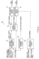
- FIG. 4 is a block diagram schematically illustrating a configuration example of a constant direct-current voltage control section illustrated in FIG. 3 .
- the constant direct-current voltage control section 110 includes a subtractor 112, a proportional gain multiplier 114, an integration gain multiplier 116, an integrator 118, and an adder 119.
- the link voltage command V DCref and the direct-current voltage V DC are input to the subtractor 112, and a difference obtained by subtracting the direct-current voltage V DC from the link voltage command V DCref is output to a proportional gain multiplier 114 and the integration gain multiplier 116.
- the proportional gain multiplier 114 multiplies the input difference value (V DCref - V DC ) by a proportional gain Kp and output the obtained value to the adder 119.
- the integration gain multiplier 116 multiplies the input difference value (V DCref - Voc) by an integration gain KI and output the obtained value to the integrator 118.
- the integrator 118 integrates the value (KI ⁇ (V DCref - V DC )) input from the integration gain multiplier 116 and outputs the obtained value to the adder 119.
- the adder 119 adds a value (Kp ⁇ (V DCref - V DC )) from the proportional gain multiplier 114 and a value (KI ⁇ (V DCref - V DC )/s) input from the integrator and output a result as the direct-current section energy P DC .
- the torque computing section 120 receives the direct-current section energy P DC and the axle torque command Tref and computes a torque command T MG1 of the power generator 30 and the torque command T MG2 of the motor 60 so that the output torque of the axle 80 realizes the axle torque command Tref and the voltage of the direct-current link becomes constant.
- the torque command T MG1 , T MG2 computed by the torque computing section 120 will be described below.
- the axle torque T OUT of the axle and the direct-current section energy P DC can be determined independently by the equations (15) and (16), the axle torque T OUT may be changed to a desired value while maintaining the direct-current link voltage constant by setting the direct-current section energy P DC to be equivalent to energy consumed by the auxiliary machine 90.
- the direct-current link voltage is made a constant value by using the value computed by the constant direct-current voltage control section 110 is the direct-current section energy P DC .
- the torque command T MG1 of the power generator 30 is a sum of "-" of a first operand and "-" of a second operand, in which the first operand is obtained by dividing a product of the number of teeth Gs of the sun gear S, the rotation angular speed ⁇ R of the ring gear R, and the axle torque command T OUT by a sum of a product of the number of teeth Gs of the sun gear S and the rotation angular speed ⁇ S of the sun gear S and a product of the number of teeth G R of the ring gear R and the rotation angular speed ⁇ R of the ring gear R, and the second operand is obtained by dividing a product of the number of teeth Gs of the sun gear S and the direct-current section energy P DC by a sum of a product of the number of teeth Gs of the sun gear S and the rotation angular speed ⁇ S of the sun gear S and a product of the number of teeth G R of the ring gear R and the rotation angular speed ⁇ R of
- the torque command T MG2 of the motor 60 is a sum of a third operand and "-" of a fourth operand, in which the third operand is obtained by dividing a product of the number of teeth Gs of the sun gear S, the rotation angular speed ⁇ s of the sun gear S, and the axle torque command T OUT by a sum of a product of the number of teeth Gs of the sun gear S and the rotation angular speed ⁇ S of the sun gear S and a product of the number of teeth G R of the ring gear R and the rotation angular speed ⁇ R of the ring gear R, and the fourth operand is obtained by dividing a product of the number of teeth G R of the ring gear R and the direct-current section energy P DC by a sum of a product of the number of teeth Gs of the sun gear S and the rotation angular speed ⁇ S of the sun gear S and a product of the number of teeth G R of the ring gear R and the rotation angular speed ⁇ R of the ring gear
- the first inverter control section 42 receives the torque command T MG1 from the torque computing section 120, performs control (vector control or the like) for outputting a torque of the torque command T MG1 , and generates and outputs a gate command to the first inverter 40.
- the second inverter control section 52 receives the torque command T MG2 from the torque computing section 120, performs control (vector control or the like) for outputting a torque of the torque command T MG2 , and generates and outputs a gate command to the second inverter 50.
- the first inverter 40 and the second inverter 50 are operated by the gate command generated in a manner descried above. Therefore, even when the battery BT is not connected to the direct-current link, the direct-current link voltage is maintained constant, and an output torque T OUT that achieves the axle torque command Tref set as desired may be output from the axle 80. In other words, according to the vehicle system of the present example, a stable drive is achieved.
- FIG. 5 is a block diagram schematically illustrating a configuration example of a vehicle control apparatus of a vehicle system according to the first embodiment.
- a vehicle control apparatus CTR includes a plurality of processors, and a power generator control section MC2 configured to control a power generator 30, a motor control section MC3 configured to control a motor 60, and a master control section MC1 are operated by different processors.
- the master control section MC1 is configured to be capable of communicating with both the power generator control section MC2 and the motor control section MC3.
- the power generator control section MC2 and the motor control section MC3 cannot communicate with each other.
- the power generator control section MC2 and the motor control section MC3 can communicate with each other via communication means (not illustrated) of the master control section MC1.
- a configuration of controlling the power generator 30 and the motor 60 in cooperation with each other by the plurality of processors as described above will be described.
- a constant direct-current voltage control selecting section 130 configured to select a power generator for controlling a voltage of a direct-current link based on a rotation angular speed ⁇ MG1 of the power generator (first electric motor) 30 and a rotation angular speed ⁇ MG2 of the motor (second electric motor) 60, and output a first control signal CMD1 that is
- the first control signal CMD1 when controlling the voltage of the direct-current link by the action of the power generator 30, the first control signal CMD1 is “1” and the second control signal CMD2 is “0" (a second level different from the first level).
- the first control signal CMD1 is "0" (second level) and the second control signal CMD2 is "1".
- the voltage of the direct-current link is controlled to be constant based on an output signal from either a first constant direct-current voltage control section 110A or a second constant direct-current voltage control section 110B, and thus the first control signal CMD1 and the second control signal CMD2 are exclusively "1".
- a control section that controls the voltage of the direct-current link to rise and a control section that controls the voltage of the direct-current link to drop are created due to errors in sensors and circuits, which may cause a failure in operation of the first constant direct-current voltage control section 110A and the second constant direct-current voltage control section 110B.
- the constant direct-current voltage control section 110 includes the first constant direct-current voltage control section (first control section) 110A, the second constant direct-current voltage control section (second control section) 110B, a first switch SWA, and a second switch SWB.
- an output P DC1 of the first constant direct-current voltage control section 110A is, for example, zero.
- the first constant direct-current voltage control section 110A may be configured to receive the link voltage command V DCref and the direct-current voltage V DC , and compute and output the direct-current section energy P DC1 .
- the first constant direct-current voltage control section 110A may be configured to compute and output the direct-current section energy P DC1 irrespective of the first control signal CMD1.
- an output P DC2 of the second constant direct-current voltage control section 110B is, for example, zero.
- the second constant direct-current voltage control section 110B may be configured to receive the link voltage command V DCref and the direct-current voltage V DC , and compute and output the direct-current section energy P DC2 .
- the second constant direct-current voltage control section 110B may be configured to compute and output the direct-current section energy P DC2 irrespective of the second control signal CMD2.
- an output P DC1 of the first constant direct-current voltage control section 110A is input to a first input terminal
- an output P DC2 of the second constant direct-current voltage control section 110B is input to a second input terminal.
- an output P DC2 of the second constant direct-current voltage control section 110B is input to a third input terminal, and an output P DC1 of the first constant direct-current voltage control section 110A is input to a fourth input terminal.
- a torque computing section 120 includes a partial torque computing section 120', a first computing section 140A, a first adder 150A, a second computing section 140B, and a second adder 150B.
- the partial torque computing section 120' receives an axle torque command Tref and computes a member (first operand) relating to the axle torque command Tref in the above equation (19) and a member (third operand) relating to the axle torque command Tref of the above equation (20).
- the first computing section 140A receives a value output from the first switch SWA, and computes a member (second operand) relating to a direct-current section energy P DC in the above equation (19).
- the first adder 150A adds and outputs the first operand and the second operand.
- the second computing section 140B receives a value output from the second switch SWB and computes a member (fourth operand) relating to the direct-current section energy P DC of the equation (20) described above.
- the second adder 150B adds and outputs the third operand and the fourth operand.
- the vehicle control apparatus CTR includes the master control section MC1, the power generator control section MC2, and the motor control section MC3.
- the master control section MC1, the power generator control section MC2, and the motor control section MC3 are configured to be operated by different processors.
- the master control section MC1 includes a revolving speed determining section 100, a partial torque computing section 120', and the constant direct-current voltage control selecting section 130.
- the revolving speed determining section 100 includes a table storing revolving speeds of the internal combustion engine 10 associated with output torques of the axle 80, for example, in the same manner as the example described above.
- the revolving speed determining section 100 receives an axle torque command Tref supplied from outside, and reads and outputs the revolving speed of the internal combustion engine 10 corresponding to the axle torque command Tref.
- the partial torque computing section 120' receives the axle torque command Tref supplied from the outside, computes and outputs partial torque commands T MG1' and T MG2' which correspond to members (the first operand and the third operand described above) relating to the torque commands T MG1 and T MG2 computed by the above-described equations (19) and (20).
- T MG 1 ′ - G S ⁇ R G S ⁇ S + G R ⁇ R T ref
- T MG 2 ′ G S ⁇ S G S ⁇ S + G R ⁇ R T ref
- the constant direct-current voltage control selecting section 130 receives the rotation angular speed ⁇ MG1 of the power generator 30, a maximum torque feature T MAX-MG1 of the power generator 30, the rotation angular speed ⁇ MG2 of the motor 60, and a maximum torque feature T MAX-MG2 of the motor 60, and outputs the first control signal CMD1 and the second control signal CMD2.
- the first control signal CMD1 and the second control signal CMD2 are signals for selecting whether to control the voltage of the direct-current link constant by the power generator 30 or control the voltage of the direct-current link constant by the motor 60.
- the direct-current link is connected between a first inverter 40 configured to drive the power generator 30, which corresponds to the first electric motor, and a second inverter 50 configured to drive the motor 60, which corresponds to the second electric motor, and thus constant voltage control may be performed either by an operation of the power generator 30 or by an operation of the motor 60.
- the torque that the electric motor can generally output is limited. Assuming that a maximum torque that can be output when the electric motor rotates at an angular speed ⁇ is a maximum torque T MAX , an electric motor having a greater product of the angular speed ⁇ and the maximum torque T MAX has more capacity available for controlling the voltage of the direct-current link.
- the constant direct-current voltage control selecting section 130 compares a product of the rotation angular speed ⁇ MG1 and the maximum torque T MAX-MG1 of the power generator 30 and a product of the rotation angular speed ⁇ MG2 and a maximum torque T MAX-MG2 of the motor 60, and outputs the first control signal CMD1 and the second control signal CMD2 so as to perform voltage control of the direct-current link by using an electric motor having a larger product of the rotation angular speed and the maximum torque.
- the constant direct-current voltage control selecting section 130 outputs, for example, the first control signal CMD1 "1” and the second control signal CMD2 "0” when ⁇ MG1 T MAX-MG1 > ⁇ MG2 T MAX-MG2 is established, and outputs the first control signal CMD1 "0” and the second control signal CMD2 "1” when ⁇ MG1 T MAX-MG1 ⁇ ⁇ MG2 T MAX-MG2 is established.
- the first control signal CMD1 and the second control signal CMD2 issue, for example, a voltage control stop command when the value is "0", and issue a voltage control operation command when the value is "1".
- the power generator control section MC2 includes the first constant direct-current voltage control section 110A, the first computing section 140A, the first adder 150A, a first inverter control section 42, and the first switch SWA.
- the first constant direct-current voltage control section 110A receives the first control signal CMD1, a target value V DCref of the voltage of the direct-current link, and the direct voltage detecting value V DC , and computes and outputs a value of the direct-current section energy P DC1 so that a difference between the link voltage command V DCref and the direct voltage detecting value V DC becomes zero when the value of the first control signal CMD1 is "1" in the same manner as the constant direct-current voltage control section 110 of the example described above.
- the direct-current section energy P DC1 is supplied to one of input terminals of the switch SWA and other one of input terminals of a switch SWB described later via the master control section MC1.
- the first switch SWA includes two input terminals (first input terminal and second input terminal) and one output terminal, and switches so that either the first input terminal or the second input terminal is electrically connected to the output terminal depending on the value of the first control signal CMD1.
- the switch SWA electrically connects the first input terminal and the output terminal when the value of the first control signal CMD1 is "1", and electrically connects the second input terminal and the output terminal when the value of the control signal CMD1 is "0".
- the first computing section 140A receives either one of the direct-current section energy P DC1 and the direct-current section energy P DC2 from the switch SWA, and outputs a constant voltage command AVR1 given below, which corresponds to the member (the second operand) relating to the direct-current section energy P DC of the torque command T MG1 computed by the above equations (19) and (20) to the first adder 150A.
- the first adder 150A receives a partial torque command T MG1 ' output from the partial torque computing section 120' of the master control section MC1 and the constant voltage command AVR1 output from the first computing section 140A, and outputs a sum of the partial torque command T MG1 ' and the constant voltage command AVR1 to the first inverter control section 42 as the torque command T MG1 of the power generator 30.
- the first inverter control section 42 receives the torque command T MG1 in the same manner as in the example described above, performs control (vector control or the like) for outputting a torque of the torque command T MG1 , and generates and outputs a gate command to the first inverter 40.
- the motor control section MC3 includes the second constant direct-current voltage control section 110B, the second computing section 140B, the second adder 150B, a second inverter control section 52, and the second switch SWB.
- the second constant direct-current voltage control section 110B receives the second control signal CMD2, a target value V DCref of the voltage of the direct-current link, and the direct voltage detecting value V DC , and computes and outputs a value of the direct-current section energy P DC2 so that a difference between the link voltage command V DCref and the direct voltage detecting value V DC becomes zero when the value of the second control signal CMD2 is "1" in the same manner as the constant direct-current voltage control section 110 of the example described above.
- the direct-current section energy P DC2 is supplied to a third input terminal of the second switch SWB and the second input terminals of the switch SWA described above via the master control section MC1.
- the second switch SWB includes two input terminals (third input terminal and fourth input terminal) and an output terminal, and switches so that either the third input terminal or the fourth input terminal is electrically connected to the output terminal depending on the value of the second control signal CMD2.
- the second switch SWB electrically connects the third input terminal and the output terminal when the value of the second control signal CMD2 is "1", and electrically connects the fourth input terminal and the output terminal when the value of the second control signal CMD2 is "0".
- the second computing section 140B receives either one of the direct-current section energy P DC2 and the direct-current section energy P DC1 from the second switch SWB, and outputs a constant voltage command AVR2 given below, which corresponds to the member (the fourth operand) relating to the direct-current section energy PDC of the torque command T MG2 computed by the above equations (19) and (20) to the adder 150B.
- the second adder 150B receives a partial torque command T MG2 ' output from the partial torque computing section 120' of the master control section MC1 and the constant voltage command AVR2 output from the second computing section 140B, and outputs a sum of the partial torque command Torque command T MG2 ' and the constant voltage command AVR2 to the second inverter control section 52 as the torque command T MG2 of the motor 60.
- the second inverter control section 52 receives the torque command T MG2 in the same manner as in the example described above, performs control (vector control or the like) for outputting a torque of the torque command T MG2 , and generates and outputs a gate command to the second inverter 50.
- T MG 1 ⁇ G S ⁇ R G S ⁇ S + G R ⁇ R T ref ⁇ G S G S ⁇ S + G R ⁇ R P DC 1
- T MG 2 G S ⁇ S G S ⁇ S + G R ⁇ R T ref ⁇ G R G S ⁇ S + G R ⁇ R P DC 1
- T MG 1 ⁇ G S ⁇ R G S ⁇ S + G R ⁇ R T ref ⁇ G S G S ⁇ S + G R ⁇ R P DC 2
- T MG 2 G S ⁇ S G S ⁇ S + G R ⁇ R T ref ⁇ G R G S ⁇ S + G R ⁇ R P DC 2
- the output (direct-current section energy P DC ) of the constant direct-current voltage control section 110 is fed to the first inverter control section 42 and the second inverter control section 52 without delay, follow-up to variation of consumption energy of the auxiliary machine 90 is enabled.
- the configuration that controls the power generator 30 and the configuration that controls the motor 60 are operated by processors different from each other, mutual issue of commands between the configurations may delay and thus the torque response delays correspondingly.
- the motor 60 may not receive the value of the direct-current section energy immediately due to the delay of communication between the control section of the power generator 30 and the control section of the motor 60, and thus may not be able to follow up the change in consumed energy of the auxiliary machine immediately. In such cases, the voltage of the direct-current link varies, and thus the operation of the entire vehicle system may stop.
- the control section of the electric motor which is not involved in voltage control receives the direct-current section energy P DC from the control section of the electric motor which is involved in the voltage control and thus follow-up is enabled even when the voltage of the direct-current link is changed.
- the delay is as small as a range from 10 ms to 100 ms. In other words, according to the vehicle system of the present embodiment, a stable drive is achieved.
- the constant direct-current voltage control selecting section 130 is configured to control the voltage by the electric motor having a larger value in product of the rotation angular speed and the maximum torque.
- a configuration such that only the rotation angular speeds are compared to select the electric motor having a larger rotation angular speed for the voltage control is also applicable.
- the present embodiment may be applied also to, for example, a vehicle having no sensor for the rotation angular speed.
- the vehicle system according to the present embodiment is provided with a configuration considering an operation when the vehicle is stopped, that is, when the power generator 30 is stopped.
- FIG. 6 is a block diagram schematically illustrating a configuration of a vehicle control apparatus of a vehicle system according to the second embodiment.
- a control apparatus CTR is further provided with a vehicle stop determination section 150 in addition to the control apparatus CTR in the vehicle system according to the first embodiment.
- the vehicle stop determination 150 receives a braking state supplied from outside, an axle torque command Tref, and a vehicle traveling speed ⁇ R , and outputs a stop command to the second inverter control section 52.
- a stop command is set to "1"
- the stop command is set to "0".
- the rotation angular speed ⁇ MG2 of the motor is equal to "0". Therefore, when the vehicle is stopped, the motor 60 does not supply energy to the direct-current link, and thus the motor 60 does not affect the voltage control of the direct-current link.
- a torque generated in the motor 60 is absorbed by a brake mechanism instead. Therefore, when the vehicle is stopped, the operation of the second inverter 50 may be stopped. Consequently, a failure rate may be reduced by not performing unnecessary operations and, simultaneously, an increase in temperature due to a loss of the electric energy of the motor 60 and the second inverter 50 may be suppressed. In other words, according to the vehicle system of the present embodiment, a stable drive is achieved.
- torque commands T MG1 , T MG2 may be expressed as given below.
- T MG 1 ⁇ 1 ⁇ S P DC
- T MG 2 0 Operation stop
- FIG. 7 is a block diagram schematically illustrating another configuration example of the vehicle control apparatus of the vehicle system according to the second embodiment.
- the vehicle control apparatus CTR is further provided with the vehicle stop determination section 150 in addition to the vehicle control apparatus in the vehicle system according to the first embodiment.
- the vehicle stop determination 150 receives a braking state supplied from outside, a torque command Tref, and a vehicle traveling speed ⁇ R, and outputs a stop command to the second inverter control section 52.
- a torque command Tref When brake is applied, the value of an axle torque command Tref is "0", and a vehicle traveling speed is "0", the vehicle stop determination section 150 determines that the vehicle is stopped, and a stop command is set to "1", while when the above-described conditions are not satisfied, the stop command is set to "0".
Landscapes
- Engineering & Computer Science (AREA)
- Transportation (AREA)
- Mechanical Engineering (AREA)
- Chemical & Material Sciences (AREA)
- Combustion & Propulsion (AREA)
- Power Engineering (AREA)
- Life Sciences & Earth Sciences (AREA)
- Sustainable Development (AREA)
- Sustainable Energy (AREA)
- Automation & Control Theory (AREA)
- Electric Propulsion And Braking For Vehicles (AREA)
- Hybrid Electric Vehicles (AREA)
Claims (2)
- Fahrzeugsystem, das Folgendes umfasst:einen Verbrennungsmotor (10);einen ersten Elektromotor (30);einen zweiten Elektromotor (60);einen ersten Kraftübertragungsmechanismus (20), der dazu ausgestaltet ist, eine Umdrehung des Verbrennungsmotors (10) auf den ersten Elektromotor (30) und einen zweiten Kraftübertragungsmechanismus (70) zu übertragen;eine Achse (80), die dazu ausgestaltet ist, sich dadurch, dass sie an den zweiten Kraftübertragungsmechanismus (70) gekoppelt ist, zu drehen,wobei der zweite Kraftübertragungsmechanismus (70) die Umdrehung zwischen dem zweiten Elektromotor (60) und der Achse (80) undzwischen dem ersten Kraftübertragungsmechanismus (20) und der Achse (80) überträgt;der erste Kraftübertragungsmechanismus (20) Folgendes umfasst:einen Planetenträger, der dazu ausgestaltet ist, sich durch Energie, die von dem Verbrennungsmotor (10) erzeugt wird, zu drehen; ein Sonnenrad, das dazu ausgestaltet ist, eine Drehkraft auf den ersten Elektromotor (30) zu übertragen; und ein Hohlrad, das dazu ausgestaltet ist, eine Drehkraft auf den zweiten Kraftübertragungsmechanismus (70) zu übertragen;einen ersten Wechselrichter (40), der dazu ausgestaltet ist, den ersten Elektromotor (30) anzutreiben;einen zweiten Wechselrichter (50), der über eine Gleichstromverbindung mit dem ersten Wechselrichter (40) verbunden ist und den zweiten Elektromotor (60) antreibt;einen Spannungsdetektor (VS), der dazu ausgestaltet ist, eine Verbindungsspannung der Gleichstromverbindung zu detektieren;eine Hauptsteuereinheit (MC1);eine erste Elektromotor-Steuereinheit (MC2), die eine erste Wechselrichtersteuereinheit (42) umfasst, die dazu ausgestaltet ist, einen Gate-Befehl an den ersten Wechselrichter (40) basierend auf einem Drehmomentbefehl (TMG1) des ersten Elektromotors (30) auszugeben; undeine zweite Elektromotor-Steuereinheit (MC3), die eine zweite Wechselrichter-Steuereinheit (52) umfasst, die dazu ausgestaltet ist,einen Gate-Befehl an den zweiten Wechselrichter (50) basierend auf einem Drehmomentbefehl (TMG2) des zweiten Elektromotors (60) auszugeben,dadurch gekennzeichnet, dassder Drehmomentbefehl des ersten Elektromotors (30) eine Summe eines ersten Operanden und eines zweiten Operanden ist, wobei der erste Operand ein negativer Wert eines Werts ist, der durch Dividieren eines Produkts einer Anzahl von Zähnen des Sonnenrads, einer Drehwinkelgeschwindigkeit des Hohlrads und eines Achsendrehmomentbefehls (Tref) durch eine Summe eines Produkts der Anzahl von Zähnen des Sonnenrads und einer Drehwinkelgeschwindigkeit des Sonnenrads und eines Produkts einer Anzahl von Zähnen des Hohlrads und der Drehwinkelgeschwindigkeit des Hohlrads erhalten wird, und der zweite Operand ein negativer Wert eines Werts ist, der durch Dividieren eines Produkts der Anzahl von Zähnen des Sonnenrads und einer Gleichstromeinheitsenergie (PDC) durch eine Summe des Produkts der Anzahl von Zähnen und der Drehwinkelgeschwindigkeit des Sonnenrads und des Produkts der Anzahl von Zähnen des Hohlrads und der Drehwinkelgeschwindigkeit des Hohlrads erhalten wird,der Drehmomentbefehl des zweiten Elektromotors (60) eine Summe eines dritten Operanden und eines vierten Operanden ist, wobei der dritte Operand durch Dividieren eines Produkts der Anzahl von Zähnen des Sonnenrads und der Drehwinkelgeschwindigkeit des Sonnenrads und des Achsendrehmomentbefehls (Tref) durch eine Summe des Produkts der Anzahl von Zähnen des Sonnenrads und der Drehwinkelgeschwindigkeit des Sonnenrads und des Produkts der Anzahl von Zähnen des Hohlrads und der Drehwinkelgeschwindigkeit des Hohlrads erhalten wird, und der vierte Operand ein negativer Wert eines Werts ist, der durch Dividieren des Produkts der Anzahl von Zähnen des Sonnenrads und der Gleichstromeinheitsenergie (PDC) durch eine Summe des Produkts der Anzahl von Zähnen des Sonnenrads und der Drehwinkelgeschwindigkeit des Sonnenrads unddes Produkts der Anzahl von Zähnen des Hohlrads und der Drehwinkelgeschwindigkeit des Hohlrads erhalten wird,die Hauptsteuereinheit (MC1) eine Teildrehmoment-Berechnungseinheit (120') umfasst, die dazu ausgestaltet ist, den Achsendrehmomentbefehl zu empfangen und den ersten Operanden und den dritten Operanden zu berechnen; und eine Konstantgleichstrom-Spannungssteuerungsauswahleinheit (130), die dazu ausgestaltet ist, einen Elektromotor zum Durchführen von Spannungssteuerung der Gleichstromverbindung basierend auf einer Drehwinkelgeschwindigkeit des ersten Elektromotors (30) und einer Drehwinkelgeschwindigkeit des zweiten Elektromotors (60) durchzuführen und ein erstes Steuersignal (CMD1) und ein zweites Steuersignal (CMD2) auszugeben, wobei das erste Steuersignal einen Wert auf einem ersten Pegel aufweist, wenn die Spannung der Gleichstromverbindung durch einen Betrieb des ersten Elektromotors (30) gesteuert wird, und einen Wert auf einem zweiten Pegel aufweist, wenn die Spannung der Gleichstromverbindung durch den zweiten Elektromotor (60) gesteuert wird, wobei das zweite Steuersignal einen Wert auf dem ersten Pegel aufweist, wenn die Spannung der Gleichstromverbindung durch einen Betrieb des zweiten Elektromotors (60) gesteuert wird, und einen Wert auf dem zweiten Pegel aufweist, wenn die Spannung der Gleichstromverbindung durch den Betrieb des ersten Elektromotors (30) gesteuert wird;die erste Elektromotorsteuereinheit (MC2) Folgendes umfasst: eine erste Steuereinheit (110A), die dazu ausgestaltet ist, einen Verbindungsspannungsbefehl und die Verbindungsspannung zu empfangen und die Gleichstromeinheitsenergie zu berechnen und auszugeben; einen ersten Schalter (SWA), der dazu ausgestaltet ist, einen ersten Eingangsanschluss und einen ersten Ausgangsanschluss zu verbinden, wenn ein Ausgang von der ersten Steuereinheit (110A) in den ersten Eingangsanschluss eingespeist wird, ein Ausgang der zweiten Steuereinheit (110B) in den zweiten Eingangsanschluss eingespeist wird, und das erste Steuersignal sich auf dem ersten Pegel befindet, und den zweiten Eingangsanschluss und den ersten Ausgangsanschluss zu verbinden, wenn das erste Steuersignal sich auf dem zweiten Pegel befindet; eine erste Berechnungseinheit (140A), die dazu ausgestaltet ist, einen Wert zu empfangen, der von dem ersten Schalter (SWA) ausgegeben wird, und den zweiten Operanden zu berechnen; und einen ersten Addierer (150A), der dazu ausgestaltet ist, eine Summe des ersten Operanden und des zweiten Operanden als den Drehmomentbefehl des ersten Elektromotors (30) auszugeben, unddie zweite Elektromotorsteuereinheit (MC3) Folgendes umfasst: eine zweite Steuereinheit (110B), die dazu ausgestaltet ist, den Verbindungsspannungsbefehl und die Verbindungsspannung zu empfangen und die Gleichstromeinheitsenergie zu berechnen und auszugeben; einen zweiten Schalter (SWB), der dazu ausgestaltet ist, einen dritten Eingangsanschluss und einen zweiten Ausgangsanschluss zu verbinden, wenn das zweite Steuersignal sich auf dem ersten Pegel befindet, und einen vierten Eingangsanschluss und den zweiten Ausgangsanschluss zu verbinden, wenn das zweite Steuersignal sich auf dem zweiten Pegel befindet, der Ausgang von der zweiten Steuereinheit (110B) in den dritten Eingangsanschluss eingespeist wird, der Ausgang der ersten Steuereinheit (110A) in den vierten Eingangsanschluss eingespeist wird; eine zweite Recheneinheit (140B), die dazu ausgestaltet ist, einen Wert zu empfangen, der von dem zweiten Schalter (SWB) ausgebeben wird, und den vierten Operanden zu berechnen; und einen zweiten Addierer (150B), der dazu ausgestaltet ist, eine Summe des dritten Operanden und des vierten Operanden als den Drehmomentbefehl des zweiten Elektromotors (60) auszugeben.
- Fahrzeugsystem nach Anspruch 1, das ferner eine Fahrzeugstopp-Bestimmungseinheit (150) umfasst, die dazu ausgestaltet ist, einen Stopp-Befehl auf einem ersten Pegel auszugeben, wenn ein Bremszustand, der von außerhalb geliefert wird, der Achsendrehmomentbefehl und eine Fahrzeugfahrgeschwindigkeit empfangen werden, der Achsendrehmomentbefehl null ist, die Fahrzeugfahrgeschwindigkeit null ist und die Bremse betätigt wird, wobeidie zweite Wechselrichter-Steuereinheit den Drehmomentbefehl des zweiten Elektromotors auf null einstellt und den Gate-Befehl ausgibt,wenn die zweite Wechselrichtersteuereinheit den Stopp-Befehl empfängt und der Stopp-Befehl sich auf dem ersten Pegel befindet.
Applications Claiming Priority (2)
| Application Number | Priority Date | Filing Date | Title |
|---|---|---|---|
| JP2016164756 | 2016-08-25 | ||
| PCT/JP2017/030584 WO2018038261A1 (ja) | 2016-08-25 | 2017-08-25 | 車両システム |
Publications (3)
| Publication Number | Publication Date |
|---|---|
| EP3597498A1 EP3597498A1 (de) | 2020-01-22 |
| EP3597498A4 EP3597498A4 (de) | 2020-06-17 |
| EP3597498B1 true EP3597498B1 (de) | 2023-03-29 |
Family
ID=61245057
Family Applications (1)
| Application Number | Title | Priority Date | Filing Date |
|---|---|---|---|
| EP17843737.2A Active EP3597498B1 (de) | 2016-08-25 | 2017-08-25 | Fahrzeugsystem |
Country Status (4)
| Country | Link |
|---|---|
| EP (1) | EP3597498B1 (de) |
| JP (1) | JP6678749B2 (de) |
| CN (1) | CN109641586B (de) |
| WO (1) | WO2018038261A1 (de) |
Family Cites Families (6)
| Publication number | Priority date | Publication date | Assignee | Title |
|---|---|---|---|---|
| JP3050125B2 (ja) | 1996-05-20 | 2000-06-12 | トヨタ自動車株式会社 | 動力出力装置および動力出力装置の制御方法 |
| JP2007068301A (ja) * | 2005-08-30 | 2007-03-15 | Nissan Motor Co Ltd | 電動車両の制御装置 |
| JP4386451B2 (ja) * | 2006-03-06 | 2009-12-16 | 株式会社日立製作所 | 電動車両の制御装置 |
| JP2013060041A (ja) * | 2011-09-12 | 2013-04-04 | Toyota Motor Corp | ハイブリッド車両およびその制御方法 |
| US9242642B2 (en) * | 2011-10-27 | 2016-01-26 | Toyota Jidosha Kabushiki Kaisha | Electrically-powered vehicle and method of controlling the same |
| US9481354B2 (en) * | 2014-05-08 | 2016-11-01 | Hyundai Motor Company | Emergency operation method of hybrid vehicle |
-
2017
- 2017-08-25 CN CN201780051460.9A patent/CN109641586B/zh active Active
- 2017-08-25 EP EP17843737.2A patent/EP3597498B1/de active Active
- 2017-08-25 WO PCT/JP2017/030584 patent/WO2018038261A1/ja not_active Ceased
- 2017-08-25 JP JP2018535785A patent/JP6678749B2/ja active Active
Also Published As
| Publication number | Publication date |
|---|---|
| EP3597498A4 (de) | 2020-06-17 |
| WO2018038261A1 (ja) | 2018-03-01 |
| CN109641586B (zh) | 2022-04-19 |
| JPWO2018038261A1 (ja) | 2019-06-24 |
| CN109641586A (zh) | 2019-04-16 |
| JP6678749B2 (ja) | 2020-04-08 |
| EP3597498A1 (de) | 2020-01-22 |
Similar Documents
| Publication | Publication Date | Title |
|---|---|---|
| US9340198B2 (en) | Drive control device of hybrid vehicle | |
| US9531315B2 (en) | Electric vehicle and control method therefor | |
| US7953525B2 (en) | Electrical powered vehicle incorporating motor and inverter, and control method therefor | |
| US10958091B2 (en) | Power supply device | |
| US9077279B2 (en) | Load drive control system for hybrid vehicle and method of controlling hybrid vehicle | |
| EP2025904A1 (de) | Steuerung für hybridfahrzeug und hybridfahrzeug | |
| JP2001119809A (ja) | ハイブリッド車両のモータ制御装置 | |
| US9499041B2 (en) | Hybrid vehicle and control method thereof | |
| US11404988B2 (en) | Inverter control method, and inverter control apparatus | |
| KR20070029802A (ko) | 동력출력장치, 동력출력장치를 탑재한 차량 및동력출력장치의 제어방법 | |
| EP4261076A1 (de) | Optimierung von regenerativem bremsen | |
| US20190149068A1 (en) | Motor controller, power converter, auxiliary power source, and method for controlling auxiliary power source | |
| JP2010141997A (ja) | 電動車両およびその制御方法 | |
| JP6561642B2 (ja) | ハイブリッド車両制御装置 | |
| US10597026B2 (en) | Hybrid vehicle and control method therefor | |
| JP2008278561A (ja) | 電気機器および電気機器の制御方法 | |
| EP3597498B1 (de) | Fahrzeugsystem | |
| US10730506B2 (en) | Hybrid vehicle and control method therefor | |
| EP3693239A1 (de) | Hybridfahrzeug | |
| JP6800659B2 (ja) | ハイブリッド車両システム | |
| US11958363B2 (en) | System and method of determining a representative measurement from multiple independent measurements of electric machine speed | |
| US20190248363A1 (en) | Motor system and control method for motor system | |
| US20190123652A1 (en) | Drive device | |
| US20230242117A1 (en) | Transmission-driven generator on an electric vehicle | |
| US20150171777A1 (en) | Method for controlling driving motor |
Legal Events
| Date | Code | Title | Description |
|---|---|---|---|
| STAA | Information on the status of an ep patent application or granted ep patent |
Free format text: STATUS: THE INTERNATIONAL PUBLICATION HAS BEEN MADE |
|
| PUAI | Public reference made under article 153(3) epc to a published international application that has entered the european phase |
Free format text: ORIGINAL CODE: 0009012 |
|
| STAA | Information on the status of an ep patent application or granted ep patent |
Free format text: STATUS: REQUEST FOR EXAMINATION WAS MADE |
|
| PUAB | Information related to the publication of an a document modified or deleted |
Free format text: ORIGINAL CODE: 0009199EPPU |
|
| PUAI | Public reference made under article 153(3) epc to a published international application that has entered the european phase |
Free format text: ORIGINAL CODE: 0009012 |
|
| 17P | Request for examination filed |
Effective date: 20190222 |
|
| AK | Designated contracting states |
Kind code of ref document: A1 Designated state(s): AL AT BE BG CH CY CZ DE DK EE ES FI FR GB GR HR HU IE IS IT LI LT LU LV MC MK MT NL NO PL PT RO RS SE SI SK SM TR |
|
| A4 | Supplementary search report drawn up and despatched |
Effective date: 20200515 |
|
| RIC1 | Information provided on ipc code assigned before grant |
Ipc: B60W 10/08 20060101ALI20200511BHEP Ipc: B60K 6/445 20071001AFI20200511BHEP Ipc: B60K 6/365 20071001ALI20200511BHEP Ipc: B60W 20/00 20160101ALI20200511BHEP Ipc: B60W 10/06 20060101ALI20200511BHEP Ipc: B60W 50/00 20060101ALN20200511BHEP Ipc: B60W 10/26 20060101ALI20200511BHEP |
|
| REG | Reference to a national code |
Ref country code: DE Ref legal event code: R079 Ref document number: 602017067279 Country of ref document: DE Free format text: PREVIOUS MAIN CLASS: B60W0010080000 Ipc: B60K0006445000 |
|
| RIC1 | Information provided on ipc code assigned before grant |
Ipc: B60W 50/00 20060101ALN20220908BHEP Ipc: B60W 10/26 20060101ALI20220908BHEP Ipc: B60W 10/06 20060101ALI20220908BHEP Ipc: B60W 10/08 20060101ALI20220908BHEP Ipc: B60W 20/00 20160101ALI20220908BHEP Ipc: B60K 6/365 20071001ALI20220908BHEP Ipc: B60K 6/445 20071001AFI20220908BHEP |
|
| GRAP | Despatch of communication of intention to grant a patent |
Free format text: ORIGINAL CODE: EPIDOSNIGR1 |
|
| STAA | Information on the status of an ep patent application or granted ep patent |
Free format text: STATUS: GRANT OF PATENT IS INTENDED |
|
| INTG | Intention to grant announced |
Effective date: 20221017 |
|
| GRAS | Grant fee paid |
Free format text: ORIGINAL CODE: EPIDOSNIGR3 |
|
| GRAA | (expected) grant |
Free format text: ORIGINAL CODE: 0009210 |
|
| STAA | Information on the status of an ep patent application or granted ep patent |
Free format text: STATUS: THE PATENT HAS BEEN GRANTED |
|
| AK | Designated contracting states |
Kind code of ref document: B1 Designated state(s): AL AT BE BG CH CY CZ DE DK EE ES FI FR GB GR HR HU IE IS IT LI LT LU LV MC MK MT NL NO PL PT RO RS SE SI SK SM TR |
|
| REG | Reference to a national code |
Ref country code: CH Ref legal event code: EP |
|
| REG | Reference to a national code |
Ref country code: DE Ref legal event code: R096 Ref document number: 602017067279 Country of ref document: DE |
|
| REG | Reference to a national code |
Ref country code: AT Ref legal event code: REF Ref document number: 1556441 Country of ref document: AT Kind code of ref document: T Effective date: 20230415 |
|
| REG | Reference to a national code |
Ref country code: IE Ref legal event code: FG4D |
|
| REG | Reference to a national code |
Ref country code: LT Ref legal event code: MG9D |
|
| PG25 | Lapsed in a contracting state [announced via postgrant information from national office to epo] |
Ref country code: RS Free format text: LAPSE BECAUSE OF FAILURE TO SUBMIT A TRANSLATION OF THE DESCRIPTION OR TO PAY THE FEE WITHIN THE PRESCRIBED TIME-LIMIT Effective date: 20230329 Ref country code: NO Free format text: LAPSE BECAUSE OF FAILURE TO SUBMIT A TRANSLATION OF THE DESCRIPTION OR TO PAY THE FEE WITHIN THE PRESCRIBED TIME-LIMIT Effective date: 20230629 Ref country code: LV Free format text: LAPSE BECAUSE OF FAILURE TO SUBMIT A TRANSLATION OF THE DESCRIPTION OR TO PAY THE FEE WITHIN THE PRESCRIBED TIME-LIMIT Effective date: 20230329 Ref country code: LT Free format text: LAPSE BECAUSE OF FAILURE TO SUBMIT A TRANSLATION OF THE DESCRIPTION OR TO PAY THE FEE WITHIN THE PRESCRIBED TIME-LIMIT Effective date: 20230329 Ref country code: HR Free format text: LAPSE BECAUSE OF FAILURE TO SUBMIT A TRANSLATION OF THE DESCRIPTION OR TO PAY THE FEE WITHIN THE PRESCRIBED TIME-LIMIT Effective date: 20230329 |
|
| REG | Reference to a national code |
Ref country code: NL Ref legal event code: MP Effective date: 20230329 |
|
| REG | Reference to a national code |
Ref country code: AT Ref legal event code: MK05 Ref document number: 1556441 Country of ref document: AT Kind code of ref document: T Effective date: 20230329 |
|
| PG25 | Lapsed in a contracting state [announced via postgrant information from national office to epo] |
Ref country code: SE Free format text: LAPSE BECAUSE OF FAILURE TO SUBMIT A TRANSLATION OF THE DESCRIPTION OR TO PAY THE FEE WITHIN THE PRESCRIBED TIME-LIMIT Effective date: 20230329 Ref country code: NL Free format text: LAPSE BECAUSE OF FAILURE TO SUBMIT A TRANSLATION OF THE DESCRIPTION OR TO PAY THE FEE WITHIN THE PRESCRIBED TIME-LIMIT Effective date: 20230329 Ref country code: GR Free format text: LAPSE BECAUSE OF FAILURE TO SUBMIT A TRANSLATION OF THE DESCRIPTION OR TO PAY THE FEE WITHIN THE PRESCRIBED TIME-LIMIT Effective date: 20230630 Ref country code: FI Free format text: LAPSE BECAUSE OF FAILURE TO SUBMIT A TRANSLATION OF THE DESCRIPTION OR TO PAY THE FEE WITHIN THE PRESCRIBED TIME-LIMIT Effective date: 20230329 |
|
| PG25 | Lapsed in a contracting state [announced via postgrant information from national office to epo] |
Ref country code: SM Free format text: LAPSE BECAUSE OF FAILURE TO SUBMIT A TRANSLATION OF THE DESCRIPTION OR TO PAY THE FEE WITHIN THE PRESCRIBED TIME-LIMIT Effective date: 20230329 Ref country code: RO Free format text: LAPSE BECAUSE OF FAILURE TO SUBMIT A TRANSLATION OF THE DESCRIPTION OR TO PAY THE FEE WITHIN THE PRESCRIBED TIME-LIMIT Effective date: 20230329 Ref country code: PT Free format text: LAPSE BECAUSE OF FAILURE TO SUBMIT A TRANSLATION OF THE DESCRIPTION OR TO PAY THE FEE WITHIN THE PRESCRIBED TIME-LIMIT Effective date: 20230731 Ref country code: ES Free format text: LAPSE BECAUSE OF FAILURE TO SUBMIT A TRANSLATION OF THE DESCRIPTION OR TO PAY THE FEE WITHIN THE PRESCRIBED TIME-LIMIT Effective date: 20230329 Ref country code: EE Free format text: LAPSE BECAUSE OF FAILURE TO SUBMIT A TRANSLATION OF THE DESCRIPTION OR TO PAY THE FEE WITHIN THE PRESCRIBED TIME-LIMIT Effective date: 20230329 Ref country code: AT Free format text: LAPSE BECAUSE OF FAILURE TO SUBMIT A TRANSLATION OF THE DESCRIPTION OR TO PAY THE FEE WITHIN THE PRESCRIBED TIME-LIMIT Effective date: 20230329 |
|
| PG25 | Lapsed in a contracting state [announced via postgrant information from national office to epo] |
Ref country code: SK Free format text: LAPSE BECAUSE OF FAILURE TO SUBMIT A TRANSLATION OF THE DESCRIPTION OR TO PAY THE FEE WITHIN THE PRESCRIBED TIME-LIMIT Effective date: 20230329 Ref country code: PL Free format text: LAPSE BECAUSE OF FAILURE TO SUBMIT A TRANSLATION OF THE DESCRIPTION OR TO PAY THE FEE WITHIN THE PRESCRIBED TIME-LIMIT Effective date: 20230329 Ref country code: IS Free format text: LAPSE BECAUSE OF FAILURE TO SUBMIT A TRANSLATION OF THE DESCRIPTION OR TO PAY THE FEE WITHIN THE PRESCRIBED TIME-LIMIT Effective date: 20230729 |
|
| REG | Reference to a national code |
Ref country code: DE Ref legal event code: R097 Ref document number: 602017067279 Country of ref document: DE |
|
| PG25 | Lapsed in a contracting state [announced via postgrant information from national office to epo] |
Ref country code: DK Free format text: LAPSE BECAUSE OF FAILURE TO SUBMIT A TRANSLATION OF THE DESCRIPTION OR TO PAY THE FEE WITHIN THE PRESCRIBED TIME-LIMIT Effective date: 20230329 Ref country code: CZ Free format text: LAPSE BECAUSE OF FAILURE TO SUBMIT A TRANSLATION OF THE DESCRIPTION OR TO PAY THE FEE WITHIN THE PRESCRIBED TIME-LIMIT Effective date: 20230329 |
|
| PLBE | No opposition filed within time limit |
Free format text: ORIGINAL CODE: 0009261 |
|
| STAA | Information on the status of an ep patent application or granted ep patent |
Free format text: STATUS: NO OPPOSITION FILED WITHIN TIME LIMIT |
|
| 26N | No opposition filed |
Effective date: 20240103 |
|
| PG25 | Lapsed in a contracting state [announced via postgrant information from national office to epo] |
Ref country code: MC Free format text: LAPSE BECAUSE OF FAILURE TO SUBMIT A TRANSLATION OF THE DESCRIPTION OR TO PAY THE FEE WITHIN THE PRESCRIBED TIME-LIMIT Effective date: 20230329 |
|
| REG | Reference to a national code |
Ref country code: CH Ref legal event code: PL |
|
| PG25 | Lapsed in a contracting state [announced via postgrant information from national office to epo] |
Ref country code: MC Free format text: LAPSE BECAUSE OF FAILURE TO SUBMIT A TRANSLATION OF THE DESCRIPTION OR TO PAY THE FEE WITHIN THE PRESCRIBED TIME-LIMIT Effective date: 20230329 |
|
| PG25 | Lapsed in a contracting state [announced via postgrant information from national office to epo] |
Ref country code: LU Free format text: LAPSE BECAUSE OF NON-PAYMENT OF DUE FEES Effective date: 20230825 |
|
| PG25 | Lapsed in a contracting state [announced via postgrant information from national office to epo] |
Ref country code: LU Free format text: LAPSE BECAUSE OF NON-PAYMENT OF DUE FEES Effective date: 20230825 Ref country code: CH Free format text: LAPSE BECAUSE OF NON-PAYMENT OF DUE FEES Effective date: 20230831 |
|
| PG25 | Lapsed in a contracting state [announced via postgrant information from national office to epo] |
Ref country code: SI Free format text: LAPSE BECAUSE OF FAILURE TO SUBMIT A TRANSLATION OF THE DESCRIPTION OR TO PAY THE FEE WITHIN THE PRESCRIBED TIME-LIMIT Effective date: 20230329 |
|
| REG | Reference to a national code |
Ref country code: BE Ref legal event code: MM Effective date: 20230831 |
|
| REG | Reference to a national code |
Ref country code: IE Ref legal event code: MM4A |
|
| PG25 | Lapsed in a contracting state [announced via postgrant information from national office to epo] |
Ref country code: SI Free format text: LAPSE BECAUSE OF FAILURE TO SUBMIT A TRANSLATION OF THE DESCRIPTION OR TO PAY THE FEE WITHIN THE PRESCRIBED TIME-LIMIT Effective date: 20230329 Ref country code: IT Free format text: LAPSE BECAUSE OF FAILURE TO SUBMIT A TRANSLATION OF THE DESCRIPTION OR TO PAY THE FEE WITHIN THE PRESCRIBED TIME-LIMIT Effective date: 20230329 |
|
| PG25 | Lapsed in a contracting state [announced via postgrant information from national office to epo] |
Ref country code: IE Free format text: LAPSE BECAUSE OF NON-PAYMENT OF DUE FEES Effective date: 20230825 |
|
| PG25 | Lapsed in a contracting state [announced via postgrant information from national office to epo] |
Ref country code: IE Free format text: LAPSE BECAUSE OF NON-PAYMENT OF DUE FEES Effective date: 20230825 Ref country code: FR Free format text: LAPSE BECAUSE OF NON-PAYMENT OF DUE FEES Effective date: 20230831 |
|
| PG25 | Lapsed in a contracting state [announced via postgrant information from national office to epo] |
Ref country code: BE Free format text: LAPSE BECAUSE OF NON-PAYMENT OF DUE FEES Effective date: 20230831 |
|
| PG25 | Lapsed in a contracting state [announced via postgrant information from national office to epo] |
Ref country code: BG Free format text: LAPSE BECAUSE OF FAILURE TO SUBMIT A TRANSLATION OF THE DESCRIPTION OR TO PAY THE FEE WITHIN THE PRESCRIBED TIME-LIMIT Effective date: 20230329 |
|
| PG25 | Lapsed in a contracting state [announced via postgrant information from national office to epo] |
Ref country code: BG Free format text: LAPSE BECAUSE OF FAILURE TO SUBMIT A TRANSLATION OF THE DESCRIPTION OR TO PAY THE FEE WITHIN THE PRESCRIBED TIME-LIMIT Effective date: 20230329 |
|
| PG25 | Lapsed in a contracting state [announced via postgrant information from national office to epo] |
Ref country code: CY Free format text: LAPSE BECAUSE OF FAILURE TO SUBMIT A TRANSLATION OF THE DESCRIPTION OR TO PAY THE FEE WITHIN THE PRESCRIBED TIME-LIMIT; INVALID AB INITIO Effective date: 20170825 |
|
| PG25 | Lapsed in a contracting state [announced via postgrant information from national office to epo] |
Ref country code: HU Free format text: LAPSE BECAUSE OF FAILURE TO SUBMIT A TRANSLATION OF THE DESCRIPTION OR TO PAY THE FEE WITHIN THE PRESCRIBED TIME-LIMIT; INVALID AB INITIO Effective date: 20170825 |
|
| PGFP | Annual fee paid to national office [announced via postgrant information from national office to epo] |
Ref country code: DE Payment date: 20250702 Year of fee payment: 9 |
|
| PGFP | Annual fee paid to national office [announced via postgrant information from national office to epo] |
Ref country code: GB Payment date: 20250703 Year of fee payment: 9 |
|
| REG | Reference to a national code |
Ref country code: DE Ref legal event code: R081 Ref document number: 602017067279 Country of ref document: DE Owner name: KABUSHIKI KAISHA TOSHIBA, JP Free format text: FORMER OWNERS: KABUSHIKI KAISHA TOSHIBA, TOKYO, JP; TOSHIBA INFRASTRUCTURE SYSTEMS & SOLUTIONS CORPORATION, KAWASAKI-SHI, KANAGAWA, JP Ref country code: DE Ref legal event code: R082 Ref document number: 602017067279 Country of ref document: DE Representative=s name: GRAMM, LINS & PARTNER PATENT- UND RECHTSANWAEL, DE |
|
| PG25 | Lapsed in a contracting state [announced via postgrant information from national office to epo] |
Ref country code: TR Free format text: LAPSE BECAUSE OF FAILURE TO SUBMIT A TRANSLATION OF THE DESCRIPTION OR TO PAY THE FEE WITHIN THE PRESCRIBED TIME-LIMIT Effective date: 20230329 |
|
| REG | Reference to a national code |
Ref country code: GB Ref legal event code: 732E Free format text: REGISTERED BETWEEN 20260102 AND 20260107 |