EP3597559B1 - Verbundbehälterdeckel - Google Patents
Verbundbehälterdeckel Download PDFInfo
- Publication number
- EP3597559B1 EP3597559B1 EP18766963.5A EP18766963A EP3597559B1 EP 3597559 B1 EP3597559 B1 EP 3597559B1 EP 18766963 A EP18766963 A EP 18766963A EP 3597559 B1 EP3597559 B1 EP 3597559B1
- Authority
- EP
- European Patent Office
- Prior art keywords
- upper lid
- mouth portion
- lid
- container mouth
- engaging
- Prior art date
- Legal status (The legal status is an assumption and is not a legal conclusion. Google has not performed a legal analysis and makes no representation as to the accuracy of the status listed.)
- Active
Links
Images



Classifications
-
- B—PERFORMING OPERATIONS; TRANSPORTING
- B65—CONVEYING; PACKING; STORING; HANDLING THIN OR FILAMENTARY MATERIAL
- B65D—CONTAINERS FOR STORAGE OR TRANSPORT OF ARTICLES OR MATERIALS, e.g. BAGS, BARRELS, BOTTLES, BOXES, CANS, CARTONS, CRATES, DRUMS, JARS, TANKS, HOPPERS, FORWARDING CONTAINERS; ACCESSORIES, CLOSURES, OR FITTINGS THEREFOR; PACKAGING ELEMENTS; PACKAGES
- B65D47/00—Closures with filling and discharging, or with discharging, devices
- B65D47/04—Closures with discharging devices other than pumps
- B65D47/043—Closures with discharging devices other than pumps with pouring baffles, e.g. for controlling the flow
-
- B—PERFORMING OPERATIONS; TRANSPORTING
- B65—CONVEYING; PACKING; STORING; HANDLING THIN OR FILAMENTARY MATERIAL
- B65D—CONTAINERS FOR STORAGE OR TRANSPORT OF ARTICLES OR MATERIALS, e.g. BAGS, BARRELS, BOTTLES, BOXES, CANS, CARTONS, CRATES, DRUMS, JARS, TANKS, HOPPERS, FORWARDING CONTAINERS; ACCESSORIES, CLOSURES, OR FITTINGS THEREFOR; PACKAGING ELEMENTS; PACKAGES
- B65D47/00—Closures with filling and discharging, or with discharging, devices
- B65D47/04—Closures with discharging devices other than pumps
- B65D47/06—Closures with discharging devices other than pumps with pouring spouts or tubes; with discharge nozzles or passages
- B65D47/12—Closures with discharging devices other than pumps with pouring spouts or tubes; with discharge nozzles or passages having removable closures
- B65D47/122—Threaded caps
- B65D47/123—Threaded caps with internal parts
-
- B—PERFORMING OPERATIONS; TRANSPORTING
- B65—CONVEYING; PACKING; STORING; HANDLING THIN OR FILAMENTARY MATERIAL
- B65D—CONTAINERS FOR STORAGE OR TRANSPORT OF ARTICLES OR MATERIALS, e.g. BAGS, BARRELS, BOTTLES, BOXES, CANS, CARTONS, CRATES, DRUMS, JARS, TANKS, HOPPERS, FORWARDING CONTAINERS; ACCESSORIES, CLOSURES, OR FITTINGS THEREFOR; PACKAGING ELEMENTS; PACKAGES
- B65D51/00—Closures not otherwise provided for
- B65D51/18—Arrangements of closures with protective outer cap-like covers or of two or more co-operating closures
-
- B—PERFORMING OPERATIONS; TRANSPORTING
- B65—CONVEYING; PACKING; STORING; HANDLING THIN OR FILAMENTARY MATERIAL
- B65D—CONTAINERS FOR STORAGE OR TRANSPORT OF ARTICLES OR MATERIALS, e.g. BAGS, BARRELS, BOTTLES, BOXES, CANS, CARTONS, CRATES, DRUMS, JARS, TANKS, HOPPERS, FORWARDING CONTAINERS; ACCESSORIES, CLOSURES, OR FITTINGS THEREFOR; PACKAGING ELEMENTS; PACKAGES
- B65D51/00—Closures not otherwise provided for
- B65D51/24—Closures not otherwise provided for combined or co-operating with auxiliary devices for non-closing purposes
- B65D51/248—Closures not otherwise provided for combined or co-operating with auxiliary devices for non-closing purposes the closure being provided with transient audible or visual signaling means, e.g. for indicating dispensing, or other illuminating or acoustic devices, e.g. whistles
-
- B—PERFORMING OPERATIONS; TRANSPORTING
- B65—CONVEYING; PACKING; STORING; HANDLING THIN OR FILAMENTARY MATERIAL
- B65D—CONTAINERS FOR STORAGE OR TRANSPORT OF ARTICLES OR MATERIALS, e.g. BAGS, BARRELS, BOTTLES, BOXES, CANS, CARTONS, CRATES, DRUMS, JARS, TANKS, HOPPERS, FORWARDING CONTAINERS; ACCESSORIES, CLOSURES, OR FITTINGS THEREFOR; PACKAGING ELEMENTS; PACKAGES
- B65D2251/00—Details relating to container closures
- B65D2251/0003—Two or more closures
- B65D2251/0006—Upper closure
- B65D2251/0015—Upper closure of the 41-type
-
- B—PERFORMING OPERATIONS; TRANSPORTING
- B65—CONVEYING; PACKING; STORING; HANDLING THIN OR FILAMENTARY MATERIAL
- B65D—CONTAINERS FOR STORAGE OR TRANSPORT OF ARTICLES OR MATERIALS, e.g. BAGS, BARRELS, BOTTLES, BOXES, CANS, CARTONS, CRATES, DRUMS, JARS, TANKS, HOPPERS, FORWARDING CONTAINERS; ACCESSORIES, CLOSURES, OR FITTINGS THEREFOR; PACKAGING ELEMENTS; PACKAGES
- B65D2251/00—Details relating to container closures
- B65D2251/0003—Two or more closures
- B65D2251/0068—Lower closure
- B65D2251/0075—Lower closure of the 39-type
-
- B—PERFORMING OPERATIONS; TRANSPORTING
- B65—CONVEYING; PACKING; STORING; HANDLING THIN OR FILAMENTARY MATERIAL
- B65D—CONTAINERS FOR STORAGE OR TRANSPORT OF ARTICLES OR MATERIALS, e.g. BAGS, BARRELS, BOTTLES, BOXES, CANS, CARTONS, CRATES, DRUMS, JARS, TANKS, HOPPERS, FORWARDING CONTAINERS; ACCESSORIES, CLOSURES, OR FITTINGS THEREFOR; PACKAGING ELEMENTS; PACKAGES
- B65D2251/00—Details relating to container closures
- B65D2251/0003—Two or more closures
- B65D2251/0068—Lower closure
- B65D2251/0087—Lower closure of the 47-type
Definitions
- This invention relates to a composite container lid comprising an inner plug with a flow-out port fitted and secured to a container mouth portion and an upper lid detachably attached to the container mouth portion to cover the inner plug.
- a composite container lid comprising an outer lid (upper lid) and an inner plug with a flow-out port.
- a flow-out port is formed in the bottom portion of the cylindrical portion for flowing out the content solution, and a pole-like protrusion is rising from the central portion of the bottom portion.
- an annular protrusion is provided on the inner surface of the top plate of the outer lid of the composite container lid. The inner lid is held by the outer lid as the upper end of the pole-like protrusion is fitted into the annular protrusion.
- the composite container lid is put to cover the container mouth portion in a state where the inner lid (inner plug) is held by the outer lid (upper lid), and is fitted to the container mouth portion as the outer lid is closed.
- the outer lid is opened and is removed from the container mouth portion leaving, however, the inner lid on the container mouth portion.
- the liquid in the container flows out through the flow-out port formed in the inner lid and the funnel-like portion (flow-out guide cylinder) .
- the outer lid in the composite container lid can be attached again to the container mouth portion to which the inner lid has been attached; i.e., the container mouth portion can be resealed.
- the present inventors have forwarded the study concerning the defective closing. As a result, the inventors have discovered that a sound is generated at the time of resealing leading to the cause of defective closing.
- the outer lid is resealed by a general consumer. Therefore, if the sound is generated as above, then the consumer would erroneously take it that the outer lid is now completely resealed despite the outer lid would still have to be turned in the closing direction so as to be completely closed. As a result, there occurs such an inconvenience that the container is stored without the outer lid being closed to a sufficient degree.
- JP 2014 218279 A describes a container with inside plug preventing, with a simple structure, the generation of an impact noise caused by collision of the flange of an inside plug separation part and the inside of an upper lid.
- Patent Document
- Patent document 1 Japanese UM-A-51-75759
- an object of the present invention to provide a composite container lid comprising an inner plug with a flow-out port fitted and secured to a container mouth portion and an upper lid detachably attached to the container mouth portion so as to cover the inner plug, wherein the composite container lid is so designed as to effectively prevent the defective closing when the upper lid is to be resealed or, in other words, to effectively suppress the production of sound when the upper lid is to be resealed.
- a composite container lid comprising an inner plug with a flow-out port fitted and secured to a container mouth portion and an upper lid detachably attached to the container mouth portion so as to cover the inner plug, wherein:
- an important feature resides in the provision of the sound-suppressing protrusion on the inner surface of the top plate of the upper lid in a region surrounded by the engaging pieces or on the upper end surface of the upper lid engaging cylinder.
- the sound-suppressing protrusion is for shortening the distance between the upper end surface of the upper lid engaging cylinder and the inner surface of the top plate of the upper lid, and works to suppress the generation of sound. That is, let it be presumed a case where the upper lid was once opened and it is now attempted to seal the container mouth portion again with the upper lid that was removed therefrom. In this case, the upper lid is put on the container mouth portion to which the inner plug has been fitted and secured. The upper lid is then turned in the closing direction. Here, first, the upper end of the upper lid engaging cylinder of the inner plug enters into the region surrounded by the engaging pieces formed on the inner surface of the top plate of the upper lid.
- the upper lid is further turned in the closing direction so as to be descended, then the upper end of the upper lid engaging cylinder moves over the undercut of the engaging pieces.
- the engaging force resistance against being closed
- the upper lid descends abruptly permitting the screw thread of the upper lid to come into contact with the screw thread of the container mouth portion at one time generating, therefore, the sound.
- the sound-suppressing protrusion effectively suppresses the generation of sound.
- the distance between the upper end surface of the upper lid engaging cylinder and the inner surface of the top plate of the upper lid is adjusted by the sound-suppressing protrusion to be short. Therefore, when the upper end of the upper lid engaging cylinder moves over the undercut of the engaging pieces, the sound-suppressing protrusion readily restricts the upper end surface of the upper lid engaging cylinder. Besides, even when the engaging force (pushing force) of the undercut is released, a resisting force generates against closing the container mouth portion. As a result, even when the engaging force due to the undercut is released, the upper lid is suppressed from abruptly descending, and the screw threads are prevented from coming into quick contact with each other effectively suppressing the generation of sound.
- Fig. 1 illustrating a state where a composite container lid of the present invention is closing a container mouth portion
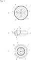
- Fig. 2 illustrating an inner plug
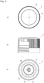
- Fig. 3 illustrating an upper lid.
- the composite container lid includes an inner plug 1 and an upper lid 3, and is attached to a container mouth portion designated at 80.
- the container mouth portion 80 is forming, in the outer surface thereof, a recessed portion 81 for holding the inner plug 1 at an upper part thereof, and is, further, forming a screw 83 for screw-fixing the upper lid 3 at a portion under the recessed portion 81.
- the composite container lid is attached to the container mouth portion 80 in a state where the inner plug 1 is held by the upper lid 3 by putting the upper lid 3 on the mouth portion 80 of the container that is containing a liquid content to close the mouth portion (i.e., by turning the upper lid 3 in a closing direction).
- the inner plug 1 is constituted by a hollow upper lid engaging cylinder 5 and with its upper end closed, and a container mouth portion-fixing member 7. That is, the upper lid engaging cylinder 5 is a member that engages with the upper lid 3 to hold it while the container mouth portion-fixing member 7 is a member that works to bring the inner plug 1 into firm and close contact with the container mouth portion 80 to fix it thereto.
- the upper lid engaging cylinder 5 is a member that temporarily engages with engaging pieces 37 (described later) formed on the inner surface of the upper lid 3, and is forming, at the upper end thereof, a circumferential protuberance 5a for temporary engagement in a shape that is swollen outward.
- the upper lid engaging cylinder 5 has a hollow shape with its upper end closed, and assumes such a shape that easily deflects inward. Therefore, the upper lid engaging cylinder 5 is capable of easily engaging with the upper lid 3 to hold it.
- the upper lid engaging cylinder 5 as a whole is tapered with its diameter contracting from the lower side toward the upper side. Due to this shape, too, the upper lid engaging cylinder 5 easily engages with the upper lid 3 to hold it.
- the container mouth portion-fixing member 7 includes a circumferential wall 9 that is so provided as to surround the upper lid engaging cylinder 5.
- the circumferential wall 9 forms, on the outer surface thereof, a swollen portion 9a that slightly swells outward (see Fig. 2(b) ).
- the swollen portion 9a therefore, comes into close contact with the inner surface of the container mouth portion 80 as shown in Fig. 1 .
- the inner surface of the circumferential wall 9 is linked to the lower end of the upper lid engaging cylinder 5 via a plurality of linking pieces 11 that are formed maintaining a predetermined distance. Therefore, spaces among the linking pieces 11 serve as a plurality of flow-out ports 13 for flowing out the liquid content.
- the linking pieces 11 have regions 11a that are tilted downward and outward from the lower end of the upper lid engaging cylinder 5. Therefore, the linking pieces 11 can be easily deflected, eventually, permitting the upper lid engaging cylinder 5 to move up and down to some extent.
- the container mouth portion-fixing member 7 further, has a low annular outer wall 15 in addition to the above circumferential wall 9, the upper inner surface of the annular outer wall 15 being continuous to the upper outer surface of the circumferential wall 9 via a horizontal wall 17.
- a flow-out guide cylinder 21 is stretching upward together with the circumferential wall 9.
- the flow-out guide cylinder 21 works as a passage for guiding the solution contained in the container when it is flown out through the flow-out ports 13.
- the flow-out guide cylinder 21 is expanding like a horn at its upper end. Upon employing the above shape, the flow-out guide cylinder 21 becomes capable of sharply discontinuing the flow out of the liquid content and suppressing the liquid content from dripping.
- the annular outer wall 15 may be omitted, and the container mouth portion-fixing member 7 may be constituted by the circumferential wall 9 and the horizontal wall 17 only. In order for the inner plug 1 to be firmly fitted and fixed to the container mouth portion 80, however, it is desired to provide the above-mentioned annular outer wall 15.
- the upper lid 3 includes a top plate 31 and a skirt portion 33 stretching downward from the outer circumferential edge of the top plate 31.
- a screw thread 35 that engages with a screw 83 formed on the container mouth portion 80.
- the thus formed upper lid 3 is detachably attached to the container mouth portion 80 so as to cover the inner plug 1 fitted and fixed to the container mouth portion 80.
- the number of the engaging pieces 37 and the size (diameter) of the region surrounded by the engaging pieces 37 should be determined depending on the size of the upper end of the upper lid engaging cylinder 5 such that the upper lid engaging cylinder 5 is allowed to enter as the engaging pieces 37 are deflected and that the undercut 37a and the circumferential protuberance 5a work together to stably hold the upper lid engaging cylinder 5 so will not to escape.
- a cylindrical seal ring 39 is provided on the outer side of the engaging piece 37. As shown in Fig. 1 , when the upper lid 3 is attached to the container mouth portion 80, the seal ring 39 comes into close contact with the inner surface of the flow-out guide cylinder 21 assuring the sealing property so that the content solution does not leak.
- an over-wrap-seam prevention protrusion 41 is formed along the circumference thereof on the outer side of the seal ring 39.
- the protrusion 41 is a member that comes into contact with the upper surface of the horizontal wall 17 of the inner plug 1 when the upper lid 3 is in its closing motion; i.e., the protrusion 41 blocks excess of closing motion (wrap-seaming) to let the consumer know that the mouth portion has been completely closed.
- the upper part of the upper lid engaging cylinder 5 of the inner plug 1 is pushed into the region surrounded by the engaging pieces 37 of the upper lid 3, and the inner plug 1 is held by the upper lid 3.
- the upper lid 3 is put on the mouth portion 80 of the container filled with the content solution; i.e. , the composite container lid is attached to the container mouth portion 80.
- the upper part of the container mouth portion 80 is fitted to between the circumferential wall 9 of the inner plug 1 and the annular outer wall 15, whereby the outer surface (swollen portion 9a) of the circumferential wall 9 comes into close contact with the inner surface of the container mouth portion, and the lower surface of the horizontal wall 17 of the inner plug 1 comes into close contact with the upper end surface 80a of the container mouth portion 80.
- the inner plug 1 is firmly fixed to the container mouth portion 80.
- a sound-suppressing protrusion 50 is provided on the inner surface of the top plate 31 of the upper lid 3. This effectively suppresses the generation of sound when the upper lid 3 removed from the container mouth portion 80 is to be resealed. Namely, this effectively prevents such an occurrence that a consumer might misunderstand the generation of sound as the completion of the closing operation (i.e., prevents defective closing).
- a general consumer would remove the upper lid 3 from the container mouth portion 80 by turning the upper lid 3 in the opening direction in a state where the composite container lid has been attached to the container mouth portion 80 as shown in Fig. 1 .
- the inner plug 1 has been firmly fitted and secured to the container mouth portion 80.
- the upper lid 3 rises, therefore, the upper part of the upper lid engaging cylinder 5 is pulled out from the region surrounded by the engaging pieces 37 of the upper lid 3 and, accordingly the upper lid 3 only is removed from the container mouth portion 80.
- the liquid content flows through the flow-out port 13 and flows out along the wall surface of the flow-out guide cylinder 21.
- the container After the liquid content is flown out by a predetermined amount, the container is returned it its upright state.
- the upper lid 3 that is removed is put on the container mouth portion 80 in which the inner plug 1 has been secured.
- the upper lid 3 is then turned in the closing direction so as to be attached to the container mouth portion 80 again.
- the over-wrap-seaming prevention protrusion 41 remains separated away from the upper surface of the horizontal wall 17 and, besides, a gap still exists between the seal ring 39 and the inner surface of the flow-out guide cylinder 21. It will, therefore, be understood that the closing operation has not yet been completed.
- the sound-suppressing protrusion 50 provided on the upper lid 3 is in a state of being contacted to the upper end surface of the upper lid engaging cylinder 5 making it, therefore, possible to effectively suppress the generation of sound when the undercut 37a of the engaging pieces 37 has moved over the circumferential protuberance 5a of the cylinder 5.
- Fig. 5 illustrates a composite container lid without the sound-suppressing protrusion 50 at a moment when the undercut 37a of the engaging pieces 37 has moved over the circumferential protuberance 5a of the cylinder 5.
- the upper end surface of the cylinder 5 in this state is separating away from the inner surface of the top plate 31.
- the undercut 37a of the engaging pieces 37 moves over the circumferential protuberance 5a of the cylinder 5
- the engagement between the undercut 37a and the circumferential protuberance 5a is released at one time. Due to the reaction thereof, therefore, the upper lid 3 descends abruptly.
- the lower surface of the screw thread 35 of the skirt portion 33 of the upper lid 3 comes in contact with the upper surface of the screw 83 of the container mouth portion 80 to generate sound.
- the sound-suppressing protrusion 50 At a moment when the undercut 37a of the engaging pieces 37 has moved over the circumferential protuberances 5a of the cylinder 5, therefore, the sound-suppressing protuberance 50 is in contact with the upper end surface of the cylinder 5. Therefore, the reaction due to the engaging force that is released, is effectively restricted, and the state of contact between the sound-suppressing protrusion 50 and the upper end of the cylinder 5 serves as resisting force against the closing operation. This prevents the upper lid 3 from abruptly descending and, therefore, also prevents the contact between the screw thread 35 and the screw 83. For instance, a gap is present between the lower surface of the screw thread 35 and the upper surface of the screw 83.
- the sound-suppressing protrusion 50 is in contact with the upper end surface of the cylinder 5 when the undercut 37a has moved over the circumferential protuberance 5a.
- Generation of sound can be suppressed to a considerable degree if rise of the cylinder 5 is limited to a certain degree despite of the reaction caused by the release of engagement.
- the sound-suppressing protrusion 50 is a member that adjusts the gap to the upper end surface of the cylinder 5 and restricts the rise of the cylinder 5 caused by the reaction.
- the sound-suppressing protrusion 50 is an annular protrusion of the shape of a ring.
- the sound-suppressing protrusion 50 is not limited to the above-mentioned shape only, but may assume a solid form or may assume the form of a plurality of fine projections.
- any protuberance that engages with the rattle-prevention piece 19 on the inner surface of the skirt portion 33 of the upper lid 3 to which the outer circumferential edge of the rattle-prevention piece 19 faces it is desired not to provide any protuberance that engages with the rattle-prevention piece 19 on the surface to which the rattle-prevention piece 19 faces until the engagement is released between the upper lid engaging cylinder 5 and the engaging pieces 37. This is because any protuberance formed on this portion may generate sound as the rattle-prevention piece 19 comes in contact therewith or is released therefrom.
Landscapes
- Engineering & Computer Science (AREA)
- Mechanical Engineering (AREA)
- Closures For Containers (AREA)
Claims (7)
- Verbundbehälterdeckel, aufweisend einen inneren Stopfen (1) mit einem Auslaufstutzen (13), der an einem Behältermündungsabschnitt (80) angesetzt und festgelegt ist, sowie einem oberen Deckel (3), der derart lösbar an dem Behältermündungsabschnitt (80) angebracht ist, dass er den inneren Stopfen (1) bedeckt, wobei:der innere Stopfen (1) einen hohlen Eingriffszylinder für den oberen Deckel (5) mit geschlossenem oberen Ende, ein Behältermündungsabschnitts-Sicherungselement (7) mit einer Umfangswand (9), die den Eingriffszylinder für den oberen Deckel (5) umgibt, sowie Gelenkstücke (11) aufweist, die eine Innenfläche der Umfangswand (9) mit dem Eingriffszylinder für den oberen Deckel (5) verbinden, um einen Auslaufstutzen (13) zu bilden;der Eingriffszylinder für den oberen Deckel (5) an einem oberen Ende an einer Außenfläche desselben mit einem umlaufenden Vorsprung zur vorübergehenden Wirkverbindung mit dem oberen Deckel (3) versehen ist;der obere Deckel (3) eine obere Platte (31) und einen Randleistenabschnitt (33) aufweist, der sich von einem Außenumfangsrand der oberen Platte (31) nach unten erstreckt und an seiner Innenfläche ein Schraubgewinde (35) zum Schraubeingriff mit dem Behältermündungsabschnitt (80) aufweist;dadurch gekennzeichnet, dassdie obere Platte (31) Eingriffsstücke (37) aufweist, die an ihrer Innenflächenseite ausgebildet sind, wobei die Eingriffsstücke (37) eine Hinterschneidung zur vorübergehenden Wirkverbindung mit dem umlaufenden Vorsprung aufweisen, der vorübergehend mit dem Eingriffszylinder für den oberen Deckel (5) in Eingriff steht; undan der Innenfläche der oberen Platte (31) in einem von den Eingriffsstücken (37) umgebenen Bereich oder an der oberen Endfläche des Eingriffszylinders für den oberen Deckel (5) ein Geräuschunterdrückungsvorsprung (50) vorgesehen ist,wobeizwischen der unteren Seitenfläche des Schraubgewindes (35) des Randleistenabschnitts (33) des oberen Deckels zum Schraubeingriff und der Außenfläche des Behältermündungsabschnitts (80) ein Spalt aufrechterhalten wird, wenn der Schallunterdrückungsvorsprung (50) einhergehend mit der absteigenden Bewegung des oberen Deckels (3) damit beginnt, in Kontakt mit der oberen Endfläche des Eingriffszylinders für den oberen Deckel (5) oder mit der Innenfläche der oberen Platte (31) des Behälterdeckels (3) zu gelangen.
- Verbundbehälterdeckel nach Anspruch 1, wobei der Schallunterdrückungsvorsprung (50) ein ringförmiger Vorsprung ist, der an der Innenfläche der oberen Platte (31) des oberen Deckels (3) gebildet ist.
- Verbundbehälterdeckel nach Anspruch 1, wobei die Eingriffsstücke (37) am Umfang ausgebildet sind und in eine Vielzahl von einen Abstand aufrechterhaltenden Segmenten geteilt sind.
- Verbundbehälterdeckel nach Anspruch 1, wobei das Behältermündungsabschnitts-Sicherungselement (7) zusätzlich zu der Umfangswand (9) eine ringförmige Außenwand (15) und eine die Umfangswand (9) mit der ringförmigen Außenwand (15) verbindende Horizontalwand (17) aufweist, es dem oberen Teil des Behältermündungsabschnitts (80) erlaubt, in einem Raum zwischen der Umfangswand (9) und der ringförmigen Außenwand (15) eingeführt und gesichert zu werden, und an dem unteren Ende der ringförmigen Außenwand (15) zum Eingriff mit der Außenfläche an dem oberen Endteil des Behältermündungsabschnitts (80) eine in der Innenfläche ausgebildete Hinterschneidung aufweist.
- Verbundbehälterdeckel nach Anspruch 1, wobei der innere Stopfen (1) zusammen mit dem oberen Deckel (3) an dem Behältermündungsabschnitt (80) angebracht wird, wenn der Eingriffszylinder für den oberen Deckel (5) vorübergehend von dem oberen Deckel (3) gehalten wird, indem er in den von den Eingriffsstücken (37) des oberen Deckels (3) umgebenen Bereich eingeführt wird, und wenn der obere Deckel (3) in diesem Zustand abgesenkt wird, während er auf dem Behältermündungsabschnitt (80) platziert ist, der innere Stopfen (1) an dem Behältermündungsabschnitt (80) verbleibt, obwohl der obere Deckel (3) geöffnet ist und vom Behältermündungsabschnitt (80) entfernt wird.
- Verbundbehälterdeckel nach Anspruch 1, wobei das Behältermündungsabschnitts-Sicherungselement (7) des inneren Stopfens (1) mit einem Ausflussleitzylinder (21) versehen ist, der sich nach oben erstreckt, und an der Innenfläche der oberen Platte (31) des oberen Deckels (3) ein Dichtungsring (39) ausgebildet ist, der in engen Kontakt mit der Innenfläche des Ausflussleitzylinders (21) gelangen soll, wenn der obere Deckel (3) geschlossen ist.
- Verbundbehälterdeckel nach Anspruch 1, wobei die obere Platte (31) des oberen Deckels (3) an ihrer Innenfläche mit einem Vorsprung zum Verhindern eines Überdrehungsverschlusses des oberen Deckels (3) versehen ist.
Applications Claiming Priority (2)
| Application Number | Priority Date | Filing Date | Title |
|---|---|---|---|
| JP2017049860A JP6894728B2 (ja) | 2017-03-15 | 2017-03-15 | 複合容器蓋 |
| PCT/JP2018/008002 WO2018168523A1 (ja) | 2017-03-15 | 2018-03-02 | 複合容器蓋 |
Publications (3)
| Publication Number | Publication Date |
|---|---|
| EP3597559A1 EP3597559A1 (de) | 2020-01-22 |
| EP3597559A4 EP3597559A4 (de) | 2021-01-20 |
| EP3597559B1 true EP3597559B1 (de) | 2023-04-19 |
Family
ID=63522207
Family Applications (1)
| Application Number | Title | Priority Date | Filing Date |
|---|---|---|---|
| EP18766963.5A Active EP3597559B1 (de) | 2017-03-15 | 2018-03-02 | Verbundbehälterdeckel |
Country Status (8)
| Country | Link |
|---|---|
| US (1) | US11325758B2 (de) |
| EP (1) | EP3597559B1 (de) |
| JP (1) | JP6894728B2 (de) |
| CN (1) | CN110546077B (de) |
| MY (1) | MY196566A (de) |
| SG (1) | SG11201907735WA (de) |
| TW (1) | TWI756379B (de) |
| WO (1) | WO2018168523A1 (de) |
Families Citing this family (4)
| Publication number | Priority date | Publication date | Assignee | Title |
|---|---|---|---|---|
| JP7005554B2 (ja) * | 2019-05-10 | 2022-02-04 | サーモス株式会社 | 蓋付き容器 |
| CN111686356B (zh) * | 2020-06-19 | 2023-01-20 | 成都利泽科技有限公司 | 一种快旋式湿化瓶 |
| MX2024006964A (es) * | 2021-12-10 | 2024-07-29 | Heinz Co Brands H J Llc | Contenedor, cierre y metodos de fabricacion y uso. |
| IT202300002118A1 (it) * | 2023-02-08 | 2024-08-08 | Capardoni & C S R L | Sistema di chiusura |
Family Cites Families (20)
| Publication number | Priority date | Publication date | Assignee | Title |
|---|---|---|---|---|
| JPS433990Y1 (de) * | 1965-10-09 | 1968-02-20 | ||
| JPS5520603Y2 (de) * | 1974-09-04 | 1980-05-17 | ||
| JPS5135453A (en) | 1974-09-19 | 1976-03-25 | Yoshio Nagamine | Pcb gedokuzaiiriakunukinomoto |
| JPS5530838Y2 (de) * | 1974-12-09 | 1980-07-23 | ||
| JPS5175759A (ja) | 1974-12-26 | 1976-06-30 | Aron Kasei Kk | Kojowankyokubuojusurugoseijushikantsugiteseikeisochi |
| GB2280895B (en) * | 1993-08-04 | 1997-12-03 | Malcolm Gordon Victory | Closure devices with compressible core seal |
| DE20115488U1 (de) * | 2001-09-20 | 2001-12-06 | Seaquist-Löffler Kunststoffwerk GmbH, 94078 Freyung | Abgabeverschluß für fließfähiges Gut enthaltende Behälter |
| US7735664B1 (en) * | 2006-04-18 | 2010-06-15 | Portola Packaging, Inc. | Tapered thread structure |
| ITMI20071310A1 (it) * | 2007-06-29 | 2008-12-30 | Guala Closures Spa | Versatore per olio. |
| EP2484600A1 (de) * | 2011-02-02 | 2012-08-08 | Obrist Closures Switzerland GmbH | Verschlusskombination für Behälter |
| JP2014525880A (ja) * | 2011-08-12 | 2014-10-02 | デサロジョス タマリット プラザ エセエレ | キャップ |
| US10086980B2 (en) * | 2013-01-25 | 2018-10-02 | Tokan Kogyo Co., Ltd. | Container sealing device |
| CN103979197B (zh) * | 2013-02-08 | 2018-05-15 | 奥布里斯特封闭瑞士有限公司 | 闭合件的改进或者关于闭合件的改进 |
| JP6084113B2 (ja) * | 2013-05-09 | 2017-02-22 | 東罐興業株式会社 | 中栓付き容器 |
| KR20150143815A (ko) * | 2013-07-12 | 2015-12-23 | 도칸 고교 가부시키가이샤 | 캡 조립체 및 그 타전 방법 |
| JP6138651B2 (ja) * | 2013-08-26 | 2017-05-31 | 株式会社吉野工業所 | 中栓付きキャップ |
| CN203740323U (zh) * | 2013-09-12 | 2014-07-30 | 赵来兴 | 一种跌落式防伪酒瓶盖 |
| JP6202527B2 (ja) * | 2013-11-29 | 2017-09-27 | 株式会社吉野工業所 | 抜栓キャップ |
| JP6415163B2 (ja) * | 2014-07-31 | 2018-10-31 | 株式会社吉野工業所 | 不正開封防止キャップ |
| JP5965039B1 (ja) * | 2015-07-30 | 2016-08-03 | 株式会社ファンケル | 開封防止機能付き容器及び開封防止部材 |
-
2017
- 2017-03-15 JP JP2017049860A patent/JP6894728B2/ja active Active
-
2018
- 2018-03-02 EP EP18766963.5A patent/EP3597559B1/de active Active
- 2018-03-02 WO PCT/JP2018/008002 patent/WO2018168523A1/ja not_active Ceased
- 2018-03-02 SG SG11201907735WA patent/SG11201907735WA/en unknown
- 2018-03-02 US US16/491,943 patent/US11325758B2/en active Active
- 2018-03-02 MY MYPI2019004822A patent/MY196566A/en unknown
- 2018-03-02 CN CN201880017604.3A patent/CN110546077B/zh active Active
- 2018-03-08 TW TW107107786A patent/TWI756379B/zh active
Also Published As
| Publication number | Publication date |
|---|---|
| SG11201907735WA (en) | 2019-09-27 |
| JP6894728B2 (ja) | 2021-06-30 |
| MY196566A (en) | 2023-04-19 |
| TW201843090A (zh) | 2018-12-16 |
| CN110546077A (zh) | 2019-12-06 |
| EP3597559A1 (de) | 2020-01-22 |
| US20200071041A1 (en) | 2020-03-05 |
| CN110546077B (zh) | 2022-02-25 |
| US11325758B2 (en) | 2022-05-10 |
| JP2018154340A (ja) | 2018-10-04 |
| TWI756379B (zh) | 2022-03-01 |
| WO2018168523A1 (ja) | 2018-09-20 |
| EP3597559A4 (de) | 2021-01-20 |
Similar Documents
| Publication | Publication Date | Title |
|---|---|---|
| EP3597559B1 (de) | Verbundbehälterdeckel | |
| EP3052400B1 (de) | Verfahren zum herstellen eines originalitätsverschlusses | |
| US20150321798A1 (en) | Container sealing device | |
| EP3655342A1 (de) | Aufsatz für einen behälterhals | |
| JP2008308218A (ja) | キャップ | |
| KR102583427B1 (ko) | 플라스틱 캡 및 그 제조 방법 | |
| KR20190126803A (ko) | 합성수지제 용기 덮개 | |
| JP6833279B2 (ja) | キャップ付き内容器 | |
| JP2014000996A (ja) | ヒンジキャップ | |
| JP2020196474A (ja) | キャップ | |
| JP7236923B2 (ja) | ヒンジキャップ | |
| JP2014162533A (ja) | 樹脂製キャップ | |
| JP5095097B2 (ja) | 容器蓋 | |
| JP2018140797A (ja) | 多条ねじ式開閉容器 | |
| JP7672189B2 (ja) | スクイズ容器 | |
| JP6261606B2 (ja) | 合成樹脂製キャップ並びにその成形型及び製造方法 | |
| CN108861023A (zh) | 防兜酒瓶盖 | |
| JP7208848B2 (ja) | プラスチックキャップの製造方法 | |
| JP7266951B2 (ja) | ヒンジキャップ | |
| HK40011173A (en) | Composite container lid | |
| JP7054504B2 (ja) | キャップ | |
| JP4937535B2 (ja) | 合成樹脂製キャップ及びその製造方法 | |
| JP7401237B2 (ja) | 容器蓋 | |
| JP7548765B2 (ja) | キャップを備えたボトル | |
| EA013557B1 (ru) | Укупорочный колпачок |
Legal Events
| Date | Code | Title | Description |
|---|---|---|---|
| STAA | Information on the status of an ep patent application or granted ep patent |
Free format text: STATUS: THE INTERNATIONAL PUBLICATION HAS BEEN MADE |
|
| PUAI | Public reference made under article 153(3) epc to a published international application that has entered the european phase |
Free format text: ORIGINAL CODE: 0009012 |
|
| STAA | Information on the status of an ep patent application or granted ep patent |
Free format text: STATUS: REQUEST FOR EXAMINATION WAS MADE |
|
| 17P | Request for examination filed |
Effective date: 20190829 |
|
| AK | Designated contracting states |
Kind code of ref document: A1 Designated state(s): AL AT BE BG CH CY CZ DE DK EE ES FI FR GB GR HR HU IE IS IT LI LT LU LV MC MK MT NL NO PL PT RO RS SE SI SK SM TR |
|
| AX | Request for extension of the european patent |
Extension state: BA ME |
|
| DAV | Request for validation of the european patent (deleted) | ||
| DAX | Request for extension of the european patent (deleted) | ||
| A4 | Supplementary search report drawn up and despatched |
Effective date: 20201221 |
|
| RIC1 | Information provided on ipc code assigned before grant |
Ipc: B65D 51/18 20060101AFI20201214BHEP Ipc: B65D 47/04 20060101ALI20201214BHEP Ipc: B65D 51/24 20060101ALI20201214BHEP Ipc: B65D 47/12 20060101ALI20201214BHEP |
|
| GRAP | Despatch of communication of intention to grant a patent |
Free format text: ORIGINAL CODE: EPIDOSNIGR1 |
|
| STAA | Information on the status of an ep patent application or granted ep patent |
Free format text: STATUS: GRANT OF PATENT IS INTENDED |
|
| RIC1 | Information provided on ipc code assigned before grant |
Ipc: B65D 51/24 20060101ALI20220826BHEP Ipc: B65D 47/12 20060101ALI20220826BHEP Ipc: B65D 47/04 20060101ALI20220826BHEP Ipc: B65D 51/18 20060101AFI20220826BHEP |
|
| INTG | Intention to grant announced |
Effective date: 20220929 |
|
| GRAS | Grant fee paid |
Free format text: ORIGINAL CODE: EPIDOSNIGR3 |
|
| GRAA | (expected) grant |
Free format text: ORIGINAL CODE: 0009210 |
|
| STAA | Information on the status of an ep patent application or granted ep patent |
Free format text: STATUS: THE PATENT HAS BEEN GRANTED |
|
| AK | Designated contracting states |
Kind code of ref document: B1 Designated state(s): AL AT BE BG CH CY CZ DE DK EE ES FI FR GB GR HR HU IE IS IT LI LT LU LV MC MK MT NL NO PL PT RO RS SE SI SK SM TR |
|
| REG | Reference to a national code |
Ref country code: GB Ref legal event code: FG4D |
|
| REG | Reference to a national code |
Ref country code: DE Ref legal event code: R096 Ref document number: 602018048620 Country of ref document: DE |
|
| REG | Reference to a national code |
Ref country code: CH Ref legal event code: EP |
|
| REG | Reference to a national code |
Ref country code: IE Ref legal event code: FG4D |
|
| REG | Reference to a national code |
Ref country code: AT Ref legal event code: REF Ref document number: 1561040 Country of ref document: AT Kind code of ref document: T Effective date: 20230515 |
|
| REG | Reference to a national code |
Ref country code: LT Ref legal event code: MG9D |
|
| REG | Reference to a national code |
Ref country code: NL Ref legal event code: MP Effective date: 20230419 |
|
| REG | Reference to a national code |
Ref country code: AT Ref legal event code: MK05 Ref document number: 1561040 Country of ref document: AT Kind code of ref document: T Effective date: 20230419 |
|
| PG25 | Lapsed in a contracting state [announced via postgrant information from national office to epo] |
Ref country code: NL Free format text: LAPSE BECAUSE OF FAILURE TO SUBMIT A TRANSLATION OF THE DESCRIPTION OR TO PAY THE FEE WITHIN THE PRESCRIBED TIME-LIMIT Effective date: 20230419 |
|
| PG25 | Lapsed in a contracting state [announced via postgrant information from national office to epo] |
Ref country code: SE Free format text: LAPSE BECAUSE OF FAILURE TO SUBMIT A TRANSLATION OF THE DESCRIPTION OR TO PAY THE FEE WITHIN THE PRESCRIBED TIME-LIMIT Effective date: 20230419 Ref country code: PT Free format text: LAPSE BECAUSE OF FAILURE TO SUBMIT A TRANSLATION OF THE DESCRIPTION OR TO PAY THE FEE WITHIN THE PRESCRIBED TIME-LIMIT Effective date: 20230821 Ref country code: NO Free format text: LAPSE BECAUSE OF FAILURE TO SUBMIT A TRANSLATION OF THE DESCRIPTION OR TO PAY THE FEE WITHIN THE PRESCRIBED TIME-LIMIT Effective date: 20230719 Ref country code: ES Free format text: LAPSE BECAUSE OF FAILURE TO SUBMIT A TRANSLATION OF THE DESCRIPTION OR TO PAY THE FEE WITHIN THE PRESCRIBED TIME-LIMIT Effective date: 20230419 Ref country code: AT Free format text: LAPSE BECAUSE OF FAILURE TO SUBMIT A TRANSLATION OF THE DESCRIPTION OR TO PAY THE FEE WITHIN THE PRESCRIBED TIME-LIMIT Effective date: 20230419 |
|
| PG25 | Lapsed in a contracting state [announced via postgrant information from national office to epo] |
Ref country code: RS Free format text: LAPSE BECAUSE OF FAILURE TO SUBMIT A TRANSLATION OF THE DESCRIPTION OR TO PAY THE FEE WITHIN THE PRESCRIBED TIME-LIMIT Effective date: 20230419 Ref country code: PL Free format text: LAPSE BECAUSE OF FAILURE TO SUBMIT A TRANSLATION OF THE DESCRIPTION OR TO PAY THE FEE WITHIN THE PRESCRIBED TIME-LIMIT Effective date: 20230419 Ref country code: LV Free format text: LAPSE BECAUSE OF FAILURE TO SUBMIT A TRANSLATION OF THE DESCRIPTION OR TO PAY THE FEE WITHIN THE PRESCRIBED TIME-LIMIT Effective date: 20230419 Ref country code: LT Free format text: LAPSE BECAUSE OF FAILURE TO SUBMIT A TRANSLATION OF THE DESCRIPTION OR TO PAY THE FEE WITHIN THE PRESCRIBED TIME-LIMIT Effective date: 20230419 Ref country code: IS Free format text: LAPSE BECAUSE OF FAILURE TO SUBMIT A TRANSLATION OF THE DESCRIPTION OR TO PAY THE FEE WITHIN THE PRESCRIBED TIME-LIMIT Effective date: 20230819 Ref country code: HR Free format text: LAPSE BECAUSE OF FAILURE TO SUBMIT A TRANSLATION OF THE DESCRIPTION OR TO PAY THE FEE WITHIN THE PRESCRIBED TIME-LIMIT Effective date: 20230419 Ref country code: GR Free format text: LAPSE BECAUSE OF FAILURE TO SUBMIT A TRANSLATION OF THE DESCRIPTION OR TO PAY THE FEE WITHIN THE PRESCRIBED TIME-LIMIT Effective date: 20230720 Ref country code: AL Free format text: LAPSE BECAUSE OF FAILURE TO SUBMIT A TRANSLATION OF THE DESCRIPTION OR TO PAY THE FEE WITHIN THE PRESCRIBED TIME-LIMIT Effective date: 20230419 |
|
| PG25 | Lapsed in a contracting state [announced via postgrant information from national office to epo] |
Ref country code: FI Free format text: LAPSE BECAUSE OF FAILURE TO SUBMIT A TRANSLATION OF THE DESCRIPTION OR TO PAY THE FEE WITHIN THE PRESCRIBED TIME-LIMIT Effective date: 20230419 |
|
| PG25 | Lapsed in a contracting state [announced via postgrant information from national office to epo] |
Ref country code: SK Free format text: LAPSE BECAUSE OF FAILURE TO SUBMIT A TRANSLATION OF THE DESCRIPTION OR TO PAY THE FEE WITHIN THE PRESCRIBED TIME-LIMIT Effective date: 20230419 |
|
| REG | Reference to a national code |
Ref country code: DE Ref legal event code: R097 Ref document number: 602018048620 Country of ref document: DE |
|
| PG25 | Lapsed in a contracting state [announced via postgrant information from national office to epo] |
Ref country code: SM Free format text: LAPSE BECAUSE OF FAILURE TO SUBMIT A TRANSLATION OF THE DESCRIPTION OR TO PAY THE FEE WITHIN THE PRESCRIBED TIME-LIMIT Effective date: 20230419 Ref country code: SK Free format text: LAPSE BECAUSE OF FAILURE TO SUBMIT A TRANSLATION OF THE DESCRIPTION OR TO PAY THE FEE WITHIN THE PRESCRIBED TIME-LIMIT Effective date: 20230419 Ref country code: RO Free format text: LAPSE BECAUSE OF FAILURE TO SUBMIT A TRANSLATION OF THE DESCRIPTION OR TO PAY THE FEE WITHIN THE PRESCRIBED TIME-LIMIT Effective date: 20230419 Ref country code: EE Free format text: LAPSE BECAUSE OF FAILURE TO SUBMIT A TRANSLATION OF THE DESCRIPTION OR TO PAY THE FEE WITHIN THE PRESCRIBED TIME-LIMIT Effective date: 20230419 Ref country code: DK Free format text: LAPSE BECAUSE OF FAILURE TO SUBMIT A TRANSLATION OF THE DESCRIPTION OR TO PAY THE FEE WITHIN THE PRESCRIBED TIME-LIMIT Effective date: 20230419 Ref country code: CZ Free format text: LAPSE BECAUSE OF FAILURE TO SUBMIT A TRANSLATION OF THE DESCRIPTION OR TO PAY THE FEE WITHIN THE PRESCRIBED TIME-LIMIT Effective date: 20230419 |
|
| PLBE | No opposition filed within time limit |
Free format text: ORIGINAL CODE: 0009261 |
|
| STAA | Information on the status of an ep patent application or granted ep patent |
Free format text: STATUS: NO OPPOSITION FILED WITHIN TIME LIMIT |
|
| 26N | No opposition filed |
Effective date: 20240122 |
|
| PG25 | Lapsed in a contracting state [announced via postgrant information from national office to epo] |
Ref country code: SI Free format text: LAPSE BECAUSE OF FAILURE TO SUBMIT A TRANSLATION OF THE DESCRIPTION OR TO PAY THE FEE WITHIN THE PRESCRIBED TIME-LIMIT Effective date: 20230419 |
|
| PG25 | Lapsed in a contracting state [announced via postgrant information from national office to epo] |
Ref country code: SI Free format text: LAPSE BECAUSE OF FAILURE TO SUBMIT A TRANSLATION OF THE DESCRIPTION OR TO PAY THE FEE WITHIN THE PRESCRIBED TIME-LIMIT Effective date: 20230419 Ref country code: IT Free format text: LAPSE BECAUSE OF FAILURE TO SUBMIT A TRANSLATION OF THE DESCRIPTION OR TO PAY THE FEE WITHIN THE PRESCRIBED TIME-LIMIT Effective date: 20230419 |
|
| REG | Reference to a national code |
Ref country code: CH Ref legal event code: PL |
|
| PG25 | Lapsed in a contracting state [announced via postgrant information from national office to epo] |
Ref country code: BG Free format text: LAPSE BECAUSE OF FAILURE TO SUBMIT A TRANSLATION OF THE DESCRIPTION OR TO PAY THE FEE WITHIN THE PRESCRIBED TIME-LIMIT Effective date: 20230419 |
|
| PG25 | Lapsed in a contracting state [announced via postgrant information from national office to epo] |
Ref country code: LU Free format text: LAPSE BECAUSE OF NON-PAYMENT OF DUE FEES Effective date: 20240302 |
|
| PG25 | Lapsed in a contracting state [announced via postgrant information from national office to epo] |
Ref country code: MC Free format text: LAPSE BECAUSE OF FAILURE TO SUBMIT A TRANSLATION OF THE DESCRIPTION OR TO PAY THE FEE WITHIN THE PRESCRIBED TIME-LIMIT Effective date: 20230419 |
|
| PG25 | Lapsed in a contracting state [announced via postgrant information from national office to epo] |
Ref country code: MC Free format text: LAPSE BECAUSE OF FAILURE TO SUBMIT A TRANSLATION OF THE DESCRIPTION OR TO PAY THE FEE WITHIN THE PRESCRIBED TIME-LIMIT Effective date: 20230419 Ref country code: LU Free format text: LAPSE BECAUSE OF NON-PAYMENT OF DUE FEES Effective date: 20240302 Ref country code: BG Free format text: LAPSE BECAUSE OF FAILURE TO SUBMIT A TRANSLATION OF THE DESCRIPTION OR TO PAY THE FEE WITHIN THE PRESCRIBED TIME-LIMIT Effective date: 20230419 |
|
| REG | Reference to a national code |
Ref country code: BE Ref legal event code: MM Effective date: 20240331 |
|
| PG25 | Lapsed in a contracting state [announced via postgrant information from national office to epo] |
Ref country code: BE Free format text: LAPSE BECAUSE OF NON-PAYMENT OF DUE FEES Effective date: 20240331 |
|
| PG25 | Lapsed in a contracting state [announced via postgrant information from national office to epo] |
Ref country code: IE Free format text: LAPSE BECAUSE OF NON-PAYMENT OF DUE FEES Effective date: 20240302 |
|
| PG25 | Lapsed in a contracting state [announced via postgrant information from national office to epo] |
Ref country code: IE Free format text: LAPSE BECAUSE OF NON-PAYMENT OF DUE FEES Effective date: 20240302 Ref country code: BE Free format text: LAPSE BECAUSE OF NON-PAYMENT OF DUE FEES Effective date: 20240331 Ref country code: CH Free format text: LAPSE BECAUSE OF NON-PAYMENT OF DUE FEES Effective date: 20240331 |
|
| PG25 | Lapsed in a contracting state [announced via postgrant information from national office to epo] |
Ref country code: CY Free format text: LAPSE BECAUSE OF FAILURE TO SUBMIT A TRANSLATION OF THE DESCRIPTION OR TO PAY THE FEE WITHIN THE PRESCRIBED TIME-LIMIT; INVALID AB INITIO Effective date: 20180302 |
|
| PG25 | Lapsed in a contracting state [announced via postgrant information from national office to epo] |
Ref country code: HU Free format text: LAPSE BECAUSE OF FAILURE TO SUBMIT A TRANSLATION OF THE DESCRIPTION OR TO PAY THE FEE WITHIN THE PRESCRIBED TIME-LIMIT; INVALID AB INITIO Effective date: 20180302 |
|
| PG25 | Lapsed in a contracting state [announced via postgrant information from national office to epo] |
Ref country code: TR Free format text: LAPSE BECAUSE OF FAILURE TO SUBMIT A TRANSLATION OF THE DESCRIPTION OR TO PAY THE FEE WITHIN THE PRESCRIBED TIME-LIMIT Effective date: 20230419 |
|
| PGFP | Annual fee paid to national office [announced via postgrant information from national office to epo] |
Ref country code: GB Payment date: 20260202 Year of fee payment: 9 |
|
| PGFP | Annual fee paid to national office [announced via postgrant information from national office to epo] |
Ref country code: DE Payment date: 20260128 Year of fee payment: 9 |
|
| PGFP | Annual fee paid to national office [announced via postgrant information from national office to epo] |
Ref country code: FR Payment date: 20260209 Year of fee payment: 9 |