EP3597574A1 - Dispositif de transport destiné au transport de recipients - Google Patents
Dispositif de transport destiné au transport de recipients Download PDFInfo
- Publication number
- EP3597574A1 EP3597574A1 EP19177810.9A EP19177810A EP3597574A1 EP 3597574 A1 EP3597574 A1 EP 3597574A1 EP 19177810 A EP19177810 A EP 19177810A EP 3597574 A1 EP3597574 A1 EP 3597574A1
- Authority
- EP
- European Patent Office
- Prior art keywords
- containers
- pucks
- star
- container
- lifting
- Prior art date
- Legal status (The legal status is an assumption and is not a legal conclusion. Google has not performed a legal analysis and makes no representation as to the accuracy of the status listed.)
- Withdrawn
Links
Images


Classifications
-
- B—PERFORMING OPERATIONS; TRANSPORTING
- B65—CONVEYING; PACKING; STORING; HANDLING THIN OR FILAMENTARY MATERIAL
- B65G—TRANSPORT OR STORAGE DEVICES, e.g. CONVEYORS FOR LOADING OR TIPPING, SHOP CONVEYOR SYSTEMS OR PNEUMATIC TUBE CONVEYORS
- B65G47/00—Article or material-handling devices associated with conveyors; Methods employing such devices
- B65G47/74—Feeding, transfer, or discharging devices of particular kinds or types
- B65G47/84—Star-shaped wheels or devices having endless travelling belts or chains, the wheels or devices being equipped with article-engaging elements
- B65G47/846—Star-shaped wheels or wheels equipped with article-engaging elements
- B65G47/847—Star-shaped wheels or wheels equipped with article-engaging elements the article-engaging elements being grippers
-
- B—PERFORMING OPERATIONS; TRANSPORTING
- B65—CONVEYING; PACKING; STORING; HANDLING THIN OR FILAMENTARY MATERIAL
- B65G—TRANSPORT OR STORAGE DEVICES, e.g. CONVEYORS FOR LOADING OR TIPPING, SHOP CONVEYOR SYSTEMS OR PNEUMATIC TUBE CONVEYORS
- B65G2201/00—Indexing codes relating to handling devices, e.g. conveyors, characterised by the type of product or load being conveyed or handled
- B65G2201/02—Articles
- B65G2201/0235—Containers
- B65G2201/0261—Puck as article support
-
- B—PERFORMING OPERATIONS; TRANSPORTING
- B65—CONVEYING; PACKING; STORING; HANDLING THIN OR FILAMENTARY MATERIAL
- B65G—TRANSPORT OR STORAGE DEVICES, e.g. CONVEYORS FOR LOADING OR TIPPING, SHOP CONVEYOR SYSTEMS OR PNEUMATIC TUBE CONVEYORS
- B65G47/00—Article or material-handling devices associated with conveyors; Methods employing such devices
- B65G47/74—Feeding, transfer, or discharging devices of particular kinds or types
- B65G47/90—Devices for picking-up and depositing articles or materials
- B65G47/902—Devices for picking-up and depositing articles or materials provided with drive systems incorporating rotary and rectilinear movements
-
- B—PERFORMING OPERATIONS; TRANSPORTING
- B65—CONVEYING; PACKING; STORING; HANDLING THIN OR FILAMENTARY MATERIAL
- B65G—TRANSPORT OR STORAGE DEVICES, e.g. CONVEYORS FOR LOADING OR TIPPING, SHOP CONVEYOR SYSTEMS OR PNEUMATIC TUBE CONVEYORS
- B65G47/00—Article or material-handling devices associated with conveyors; Methods employing such devices
- B65G47/74—Feeding, transfer, or discharging devices of particular kinds or types
- B65G47/90—Devices for picking-up and depositing articles or materials
- B65G47/907—Devices for picking-up and depositing articles or materials with at least two picking-up heads
Definitions
- the invention relates to a transport device and a method for transporting containers with a plurality of pucks, which are each designed for receiving and standing transport of a container.
- the pucks are interchangeable transport elements, each with a bottom and side support elements that support containers standing on the bottom.
- it can be cup-shaped elements with a receptacle in which a lower part of the containers is received.
- a puck with a recording shape can be selected according to the type of container currently being processed.
- the containers can be transported upright and are thereby stabilized by the corresponding receptacles or lateral support elements.
- the pucks can be conveyed, for example, by means of a conveyor belt or a conveyor chain, which pull the pucks along a transport route.
- the containers are transferred there to the treatment machine by being lifted out of the pucks.
- the containers run on a carousel. After the containers have passed through the treatment machine, they are placed in a puck again.
- the containers are removed from the pucks, for example by means of a lifting star which grips the containers and lifts them out of the puck.
- the containers are inserted into the puck by lowering the containers with the lifting star or another lifting star and inserting them into the puck.
- container gripping elements can hold the containers and can be raised or lowered together with the containers by means of a cam guide.
- the lifting height by which the containers have to be raised depends on the height of the containers. If a larger lifting height is required for a given circumference of the lifting star, the result is that the slope through which the container gripping elements pass increases. This also increases the load on the curve. A limit is thus set for the lifting height by the load capacity limits of the curve guidance with a fixed circumference of the lifting star. This means that certain container formats cannot be processed. Additional, correspondingly larger lifting stars must then be used for such container formats. Alternatively, several lifting stars arranged one behind the other can be used and divide the necessary change in height between them.
- the object on which the invention is based is therefore to provide a device which enables greater flexibility with regard to the container format.
- the transport device mentioned at the beginning comprises at least one lifting-lowering star, which is designed such that a container and the puck assigned to the container are moved apart to remove the containers from the pucks, and / or to insert the containers into the container Pucks a container and the puck assigned to the container are moved towards each other.
- the puck assigned to the container is the puck from which the container is removed.
- the puck assigned to the container is the puck into which the container is inserted.
- the total stroke required to remove a container from the puck or insert it into a puck can thus be divided into two opposing movements. For example, when removing the container, the total stroke can be distributed over the movement for lifting the container and the movement for lowering the puck. Alternatively or additionally, when inserting the containers into the pucks, the total stroke can be distributed over the movement for lowering the container and the movement for lifting the puck.
- the claimed transport device therefore has the advantage that, with the same circumference and the same gradient passed through the containers, a greater lifting height can be achieved, in particular up to twice the lifting height, if the pucks have at most the same gradient go through like the containers.
- a greater lifting height can be achieved, in particular up to twice the lifting height, if the pucks have at most the same gradient go through like the containers.
- the lifting-lowering star can in particular be designed to adjust the vertical position of the containers and the pucks. This means that the lifting and lowering star can be designed to adjust the height of both the container and the pucks.
- the height adjustment can in particular be a synchronized and opposite height adjustment. This means that the amount of height adjustment for a container and the associated puck can be the same and the direction of the height adjustment can be opposite.
- the lifting-lowering star can be designed to remove the containers from the pucks in such a way that it raises the containers and at the same time lowers the pucks.
- the lifting-lowering star can be designed and arranged such that the containers are removed from the pucks in the inlet of a treatment machine for treating the containers.
- the lifting-lowering star can be designed to insert the containers into the pucks in such a way that it lowers the containers and at the same time lifts the pucks.
- the lifting-lowering star can be designed and arranged such that the containers are inserted into the pucks in the outlet of a treatment machine or for treating the containers.
- the lifting-lowering star can comprise container gripping elements for gripping one container at a time, a first curve guide and a second curve guide.
- the lifting-lowering star can also include puck gripping elements.
- the first curve guide can be designed such that the container gripping elements for removing the containers from the pucks are raised after the containers have been gripped.
- the second curve guide can be designed such that the pucks for removing the containers from the pucks are lowered after the containers have been gripped, in particular by means of puck gripping elements.
- the first curve guide and the second curve guide can then in particular be designed such that, in order to remove the containers from the pucks, the containers are simultaneously raised and the pucks are lowered.
- the first curve guide can be designed such that the container gripping elements for inserting the containers into the pucks are lowered after the containers are gripped
- the second curve guide can be designed such that the pucks for inserting the containers into the pucks after the containers have been gripped, in particular by means of puck gripping elements.
- the first curve guide and the second curve guide can then in particular be designed in such a way that the containers are simultaneously lowered and the pucks are raised in order to insert the containers into the pucks.
- the curve can run completely or partially around the axis of rotation of the lifting-lowering star.
- the curve can, for example, run in a cylindrical surface, the cylinder axis corresponding to the axis of rotation of the lifting-lowering star.
- the curve guide can comprise, for example, a groove in the outside of a cylinder and / or a rail and / or a rod.
- the container gripping elements or puck gripping elements can comprise gripping tools for gripping and holding the container or the pucks.
- the container gripping elements or the puck gripping elements can comprise a section which interacts with the curve guidance.
- the curve guide can be designed in the form of a groove or a rail or a rod and the section can comprise an extension which engages in the groove, or can be designed and arranged such that it runs on or along the rail or rod.
- the container gripping elements or puck gripping elements can have a section which is designed in such a way and optionally interacts with other parts of the lifting-lowering star in such a way that the container gripping elements or puck gripping elements in the rotating operation of the lifting -Absenk-Sterns be taken along, i.e. revolve around the axis of rotation of the lifting-lowering star.
- these can be vertically extending recesses in a gripping element, which are attached to vertically extending guides, for example rods, in such a way that the gripping elements can be moved in the vertical direction along the guides, wherein in particular a bearing can be provided for this purpose, and that the gripping elements are carried along by the guides when they rotate in operation about the axis of rotation of the lifting-lowering star, so that the gripping elements rotate around the axis of rotation.
- individually controllable gripping elements for example driven by linear motors, are also possible.
- the transport device can, in addition or as an alternative to the puck gripping elements, also have other transport elements for the pucks in the lifting-lowering star.
- the transport elements can also include receptacles into which the pucks are placed and which support the pucks from below and to the side, for example, or hold them, for example by positive locking.
- the first curve guide and the second curve guide can be designed in such a way that, when rotating around the circumference of the lifting-lowering star, the pucks and the containers are moved towards one another in a first region and away from one another in a second region.
- the lifting-lowering star can be used for the inlet or outlet or for the inlet and outlet of a treatment machine.
- pucks and containers in the first area can be moved toward one another by the same amount as they are moved away from one another in the second area.
- the pucks can each be raised and lowered by the same amount and the containers can each be raised and lowered by the same amount.
- the course of the first curve and the course of the second curve can be opposite. This means that if the first curve runs upwards, the second curve runs downwards or, if the first curve runs downwards, the second curve runs upwards.
- the terms “below” and “above” each refer to an arrangement of the lifting-lowering star for the intended use.
- the course of the first curve and the course of the second curve can be symmetrical with respect to a plane that is perpendicular to an axis of rotation of the lifting-lowering star.
- each puck is raised a puck by the same amount by which the associated container is lowered, or the puck by the same amount lowered by which the associated container is raised.
- the transport device can comprise an inlet star and an outlet star, the lifting-lowering star being designed and arranged for the transfer of containers to the inlet star and for the transfer of containers from the outlet star.
- a common lifting and lowering star can be assigned to the inlet star and the outlet star. This is particularly space-saving and only requires the purchase of a lifting-lowering star.
- the lifting-lowering star can then be designed to remove the containers from the pucks and to insert the containers into the pucks.
- the transport device can comprise at least a first and a second lifting-lowering star, an inlet star and an outlet star, the first lifting-lowering star being designed and arranged for transferring containers to the inlet star and the second lifting-lowering star is designed and arranged to take over containers from the outlet star.
- the inlet star and the outlet star can each have their own lifting-lowering star.
- the first lifting-lowering star can then be designed to remove the containers from the pucks and the second lifting-lowering star can be designed to insert the containers into the pucks.
- the fact that the inlet star and the outlet star each have their own lifting-lowering star enables increased flexibility with regard to the arrangement and design of the inlet star and the outlet star compared to the design with a common lifting-lowering star.
- a lifting-lowering star as described above can be designed and arranged in such a way that it interacts directly with the above-mentioned container treatment machine. This means that the lifting-lowering star can transfer containers directly to the container treatment machine or take them over from it.
- the lifting-lowering star then functions as an inlet star or outlet star.
- the transport device can also comprise two of the lifting-lowering stars described above, one of the lifting-lowering stars acting as an inlet star and one of the lifting-lowering star functioning as an outlet star.
- the inlet star is a star that transfers containers to the treatment machine
- the discharge star is a star that takes containers from the treatment machine after they have passed through a treatment section of the treatment machine. Containers are transported hanging, in particular, in the inlet star and outlet star.
- a possible method for transporting pucks and containers comprises that containers are each transported standing in a puck and are removed from the pucks, for example in the inlet of a treatment machine, and / or, for example in the outlet of a treatment machine, into which pucks are inserted. If the method comprises removing the containers from the pucks, the container to be removed and the puck assigned to this container are moved apart in the opposite direction by means of a lifting-lowering star. If the method comprises inserting the containers into the pucks, the container to be inserted and the puck assigned to this container are moved towards one another by means of the lifting-lowering star.
- the container can be raised and the puck assigned to it lowered.
- the container can be lowered and the puck assigned to it raised.
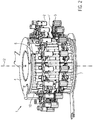
- Figures 1 to 3 schematically show in different views a transport device 1 according to the first embodiment for transporting containers 2 with a plurality of pucks 3 for receiving and standing transport of one container each.
- Figures 1 and 2 each a side view and an oblique view of the transport device.
- Figure 3 shows an oblique view in which some elements have been omitted, so that elements that are in Figures 1 and 2 are hidden, are visible.
- the pucks are each designed as a workpiece carrier with a container receptacle such that the lower part of the container stands in the container receptacle and is supported laterally by the walls of the container receptacle.
- Containers in the form of bottles are shown here by way of example in the pucks, wherein the pucks can also be designed to transport other containers.
- the transport device comprises at least one lifting-lowering star 4, which is designed such that one container and the puck assigned to the container are moved apart to remove the container from the pucks, and / or that each is used to insert the container into the pucks a container and the puck assigned to the container are moved towards one another.
- the lifting-lowering star can be designed in particular to adjust the vertical position of the containers and the pucks.
- a lifting-lowering star for removing the containers from the pucks can be arranged in the inlet of a treatment machine 5 (which is not part of the transport device) and can be designed such that it raises the containers during operation and at the same time lowers the pucks.
- a lifting-lowering star for inserting the containers into the pucks can in particular be arranged in the outlet of a treatment machine and can be designed such that it lowers the containers and at the same time lifts the pucks.
- the lifting-lowering star can also be arranged in an area which includes the inlet and the outlet and can both remove containers from pucks and insert them into pucks during operation.
- the lifting-lowering star here comprises container gripping elements 6 and puck-gripping elements 7.
- the lifting-lowering star comprises a first curve guide 8 and a second curve guide 9.
- the first curve guide is designed such that during operation it moves around the The axis of rotation of the container-gripping elements 6 rotating around the lifting-lowering star steers or specifies the shape of the orbit
- the second curve guide is designed such that during operation it directs the puck-gripping elements rotating around the axis of rotation of the lifting-lowering star or the Specifies the shape of the orbit.
- the first curve guide can be designed such that the container gripping elements for removing the containers from the pucks are raised after the containers have been gripped, and the second curve guide can be designed such that the pucks, in particular the puck gripping elements, for removing the Containers are lowered from the pucks after gripping the containers.
- the first curve guide can be designed such that the container gripping elements for inserting the containers into the pucks are lowered after the containers are gripped, and the second curve guide can be designed such that the pucks, in particular the puck gripping elements, to insert the containers into the pucks after gripping the containers.
- the curve can, for example, as in Figure 3 shown as a groove formed in a cylindrical surface or alternatively, for example, in the form of a rail or rod.
- the type of curve can be chosen as long as it is suitable for steering or specifying the orbit of the rotating containers and pucks.
- the course of the first curve and the second curve are in opposite directions.
- the cam guides are designed such that they simultaneously steer the container gripping elements and the puck gripping elements in opposite directions during operation.
- the puck gripping elements are directed downward and at the same time the container gripping elements are directed upward. This means that the pucks are lowered and the containers are raised at the same time.
- the puck gripping elements are simultaneously guided upwards and the container gripping elements downwards during operation. This means that the pucks are raised and the containers are lowered at the same time.
- this arrangement allows containers to be removed from the pucks in the first section and / or containers to be inserted into the pucks in the second section.
- the course of the first curve with respect to a plane 13 that is perpendicular to the axis of rotation 12 of the lifting-lowering star can be at least partially symmetrical to the course of the second curve, in particular in the area in which the removal or Insertion takes place.
- the lifting and lowering can be offset and / or by different amounts, as long as both the lowering and the lifting take place for removing the containers or for inserting the containers.
- the lifting-lowering star comprises vertically arranged vertical rods 10 that rotate in operation about the axis of rotation of the lifting-lowering star.
- the container gripping elements and puck gripping elements are each attached to at least one, in the example shown here two, of the rods displaceable in the vertical direction, such that the respective gripping element, when the rod rotates in operation about the axis of rotation of the lifting-lowering star, is carried along by the rod in such a way that it rotates about the axis of rotation of the lifting-lowering Sterns runs around.
- the vertical rods run through cutouts in the respective gripping elements, and bearings, for example plain bearings, can also be provided in the cutouts.
- a container gripping element and an associated puck gripping element can in particular be arranged on the same or the same vertical rods. This enables a particularly precise relative alignment of the puck gripping element and the container gripping element.
- the container gripping elements and the puck gripping elements each comprise extensions 11 which point in the direction of the axis of rotation 12 and which engage in the respective curve guidance.
- the extensions can comprise rollers that run in the curve, in this example in the groove.
- the pucks can be transported outside the lifting-lowering star, for example by means of one or more conveyor belts arranged below the pucks (not shown here) for conveying the pucks, for example by pulling the pucks along.
- the conveyor belt or belts typically run horizontally, that is, they are not raised or lowered with the pucks.
- the pucks can be transported by the lifting-lowering star using a different conveyor belt than before or further by star transport (in the lifting-lowering star and / or the discharge star) are transported.
- one or more conveyor chains or other conveyor elements can also be provided, for example.
- treatment machine 5 which is not part of the transport device, is designed for hanging transport of the container. It is in particular designed and arranged in such a way that, during operation, the containers lifted out of the pucks, in particular from an inlet star or, as in Figure 1 shown, takes over directly from the container gripping elements and / or transfers the containers after passing through a treatment section, in particular to an outlet star or directly to the container gripping elements.
- the treatment machine can be a rotary machine.
- the treatment machine can be, for example, a direct printing machine, a labeler or an inspection machine. In the treatment machine, containers are transported and treated along a treatment route, for example printed, labeled or inspected.
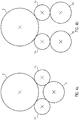
- the transport device comprises an inlet star 14 and an outlet star 15.
- the treatment machine 5 not belonging to the transport device is shown in the figures.
- the transport device comprises a lifting-lowering star 4 which is designed such that it can interact with both the inlet star and the outlet star during operation.
- the lifting-lowering star is designed and arranged in such a way that it lifts containers from the pucks during operation and transfers them to the inlet star and takes containers from the outlet star and inserts them into pucks.
- the transport device comprises a first lifting-lowering star 4a, which is designed such that it can interact with the inlet star during operation.
- the first lifting-lowering star 4a is in particular designed and arranged in such a way that it lifts containers out of the pucks during operation and transfers them to the inlet star.
- the transport device also comprises a second lifting-lowering star 4b, which is designed such that it can interact with the outlet star during operation.
- the second lifting-lowering star 4b is in particular designed and arranged in such a way that it takes over containers from the discharge star during operation and inserts them into pucks.
- a possible method for transporting pucks and containers comprises that containers are transported standing in a puck to a treatment machine. The containers are then removed from the pucks, for example in the inlet of the treatment machine. The containers are then transferred to the treatment machine and processed there. The pucks are then reinserted in pucks, for example in the outlet of a treatment machine.
- the method can also include only removing the containers or just inserting the containers.
- the method comprises the insertion and removal of the containers, this can be done by means of exactly one common lifting-lowering star or by means of one lifting-lowering star each for insertion and one lifting-lowering star for removal.
- the method comprises removing the containers from the pucks, the container to be removed and the puck assigned to this container are moved apart in the opposite direction by means of a lifting-lowering star.
- the method comprises inserting the containers into the pucks, the container to be inserted and the puck assigned to this container are moved towards one another by means of the lifting-lowering star or an additional lifting-lowering star.
- the container can be raised and the puck assigned to it lowered.
- the container can be lowered and the puck assigned to it raised.
Landscapes
- Engineering & Computer Science (AREA)
- Mechanical Engineering (AREA)
- Specific Conveyance Elements (AREA)
Applications Claiming Priority (1)
| Application Number | Priority Date | Filing Date | Title |
|---|---|---|---|
| DE202018104075.8U DE202018104075U1 (de) | 2018-07-16 | 2018-07-16 | Transportvorrichtung zum Transportieren von Behältern |
Publications (1)
| Publication Number | Publication Date |
|---|---|
| EP3597574A1 true EP3597574A1 (fr) | 2020-01-22 |
Family
ID=66690202
Family Applications (1)
| Application Number | Title | Priority Date | Filing Date |
|---|---|---|---|
| EP19177810.9A Withdrawn EP3597574A1 (fr) | 2018-07-16 | 2019-06-03 | Dispositif de transport destiné au transport de recipients |
Country Status (3)
| Country | Link |
|---|---|
| EP (1) | EP3597574A1 (fr) |
| CN (1) | CN211495917U (fr) |
| DE (1) | DE202018104075U1 (fr) |
Cited By (2)
| Publication number | Priority date | Publication date | Assignee | Title |
|---|---|---|---|---|
| EP3678966A1 (fr) * | 2017-09-04 | 2020-07-15 | Krones AG | Dispositif de transport destiné à transporter des récipients |
| EP4206100A1 (fr) * | 2021-12-21 | 2023-07-05 | Krones Ag | Étoile de transport pour transporter des récipients |
Families Citing this family (2)
| Publication number | Priority date | Publication date | Assignee | Title |
|---|---|---|---|---|
| CN113968385B (zh) * | 2021-11-23 | 2022-11-29 | 湖南品触光电科技有限公司 | 一种具有抗冲击保护的曲面屏打包运输装置 |
| DE102024129854A1 (de) * | 2024-10-15 | 2026-04-16 | Krones Aktiengesellschaft | Vorrichtung zum Transportieren von Behältern |
Citations (6)
| Publication number | Priority date | Publication date | Assignee | Title |
|---|---|---|---|---|
| US3335542A (en) * | 1962-11-09 | 1967-08-15 | Machf Van Luxemborg N V | Machine for packing and unpacking bottles |
| DE102011112300A1 (de) * | 2011-09-02 | 2013-03-07 | Khs Gmbh | Transportsystem für Packmitteln sowie Vorrichtung zum Behandeln von Packmitteln mit einem solchen Transportsystem |
| US20160046476A1 (en) * | 2013-04-03 | 2016-02-18 | Khs Gmbh | Container processing machine and method for delivering containers to and/or removing them from a container processing machine |
| DE202016100863U1 (de) * | 2016-02-18 | 2017-05-26 | Krones Ag | Transportstern |
| EP3239078A1 (fr) * | 2016-04-28 | 2017-11-01 | Tyrolon-Schulnig GmbH | Dispositif de reglage en hauteur pour un dispositif de prehension et de transport destine a saisir, retenir, guide et transporter des recipients en forme de bouteille |
| WO2018016953A2 (fr) * | 2016-07-20 | 2018-01-25 | Sluis Cigar Machinery B.V. | Support de produit |
Family Cites Families (1)
| Publication number | Priority date | Publication date | Assignee | Title |
|---|---|---|---|---|
| DE102005011130B4 (de) * | 2005-03-10 | 2007-01-25 | Sprimag Spritzmaschinenbau Gmbh & Co Kg | Vorrichtung zum Übergeben von Hohlkörpern mit einer drehangetriebenen Trommel von einem einlaufenden auf ein auslaufendes Transportmittel |
-
2018
- 2018-07-16 DE DE202018104075.8U patent/DE202018104075U1/de active Active
-
2019
- 2019-06-03 EP EP19177810.9A patent/EP3597574A1/fr not_active Withdrawn
- 2019-07-16 CN CN201921118225.1U patent/CN211495917U/zh active Active
Patent Citations (6)
| Publication number | Priority date | Publication date | Assignee | Title |
|---|---|---|---|---|
| US3335542A (en) * | 1962-11-09 | 1967-08-15 | Machf Van Luxemborg N V | Machine for packing and unpacking bottles |
| DE102011112300A1 (de) * | 2011-09-02 | 2013-03-07 | Khs Gmbh | Transportsystem für Packmitteln sowie Vorrichtung zum Behandeln von Packmitteln mit einem solchen Transportsystem |
| US20160046476A1 (en) * | 2013-04-03 | 2016-02-18 | Khs Gmbh | Container processing machine and method for delivering containers to and/or removing them from a container processing machine |
| DE202016100863U1 (de) * | 2016-02-18 | 2017-05-26 | Krones Ag | Transportstern |
| EP3239078A1 (fr) * | 2016-04-28 | 2017-11-01 | Tyrolon-Schulnig GmbH | Dispositif de reglage en hauteur pour un dispositif de prehension et de transport destine a saisir, retenir, guide et transporter des recipients en forme de bouteille |
| WO2018016953A2 (fr) * | 2016-07-20 | 2018-01-25 | Sluis Cigar Machinery B.V. | Support de produit |
Cited By (3)
| Publication number | Priority date | Publication date | Assignee | Title |
|---|---|---|---|---|
| EP3678966A1 (fr) * | 2017-09-04 | 2020-07-15 | Krones AG | Dispositif de transport destiné à transporter des récipients |
| EP3678966B1 (fr) * | 2017-09-04 | 2026-04-29 | Krones AG | Dispositif de transport pour transporter des récipients |
| EP4206100A1 (fr) * | 2021-12-21 | 2023-07-05 | Krones Ag | Étoile de transport pour transporter des récipients |
Also Published As
| Publication number | Publication date |
|---|---|
| CN211495917U (zh) | 2020-09-15 |
| DE202018104075U1 (de) | 2019-10-17 |
Similar Documents
| Publication | Publication Date | Title |
|---|---|---|
| EP3450361B1 (fr) | Dispositif de transport destiné au transport de recipients | |
| DE69819370T2 (de) | Verpackungsmaschine und verfahren zum aufsetzen von kartons | |
| EP2450306B1 (fr) | Dispositif de remplissage de récipients, en particulier avec des aliments | |
| EP2098464B1 (fr) | Dispositif de commissionnement et procédé de commissionnement | |
| EP3597574A1 (fr) | Dispositif de transport destiné au transport de recipients | |
| DE102014103671B3 (de) | Behälterbehandlungsmaschine sowie Verfahren zum Zu- und/oder Abführen von Behältern zu einer Behälterbehandlungsmaschine | |
| WO2017140397A1 (fr) | Systeme de transport en étoile | |
| EP0970900A2 (fr) | Dispositif de manutention mécanisé pour palettes | |
| DE102011010152A1 (de) | Zuführ- und Ladeeinheit | |
| DE102018222776A1 (de) | Transportanlage für Behälter | |
| DE2537268B2 (de) | Vorrichtung zum Entnehmen von Behältern aus Kästen | |
| EP1633663B1 (fr) | Dispositif pour remplir et fermer en continu des emballages en carton/matieres plastiques, ouverts d'un cote, et ensemble cellule servant au transport de tels emballages dans ledit dispositif | |
| EP3268286B1 (fr) | Dispositif d'étiquetage pour récipients | |
| EP3323745B1 (fr) | Machine de traitement de récipients et procédé de traitement de récipients | |
| DE10154889A1 (de) | Verfahren und Vorrichtung zum Einbringen von flachen Substraten in einen Aufnahmebehälter | |
| DE102015106788B4 (de) | Transportvorrichtung zur Beförderung von stehenden Behältern | |
| DE2830148A1 (de) | Flaschenzufuehr- und -ausrichteinrichtung | |
| EP3678966B1 (fr) | Dispositif de transport pour transporter des récipients | |
| DE102022127240A1 (de) | Behältertransportvorrichtung mit einer Führungsvorrichtung und Verfahren zum Transportieren von Behältern | |
| EP4610180A1 (fr) | Transport de barquettes d'emballage par un élément d'entraînement à une vitesse de vis | |
| DE102023123674A1 (de) | Vorrichtung zum Führen von Behältern, Transportsystem und Behälterbehandlungsmaschine umfassend die Vorrichtung | |
| DE2924512A1 (de) | Verfahren zur automatischen verpackung von behaeltern und vorrichtung zur durchfuehrung dieses verfahrens | |
| DE102024129854A1 (de) | Vorrichtung zum Transportieren von Behältern | |
| EP4703276A2 (fr) | Installation de traitement de récipients dotée d'un magasin de changement de format | |
| DE102024110563A1 (de) | Vorrichtung und Verfahren zum Behandeln von Behältern |
Legal Events
| Date | Code | Title | Description |
|---|---|---|---|
| PUAI | Public reference made under article 153(3) epc to a published international application that has entered the european phase |
Free format text: ORIGINAL CODE: 0009012 |
|
| STAA | Information on the status of an ep patent application or granted ep patent |
Free format text: STATUS: THE APPLICATION HAS BEEN PUBLISHED |
|
| AK | Designated contracting states |
Kind code of ref document: A1 Designated state(s): AL AT BE BG CH CY CZ DE DK EE ES FI FR GB GR HR HU IE IS IT LI LT LU LV MC MK MT NL NO PL PT RO RS SE SI SK SM TR |
|
| AX | Request for extension of the european patent |
Extension state: BA ME |
|
| STAA | Information on the status of an ep patent application or granted ep patent |
Free format text: STATUS: REQUEST FOR EXAMINATION WAS MADE |
|
| 17P | Request for examination filed |
Effective date: 20200608 |
|
| RBV | Designated contracting states (corrected) |
Designated state(s): AL AT BE BG CH CY CZ DE DK EE ES FI FR GB GR HR HU IE IS IT LI LT LU LV MC MK MT NL NO PL PT RO RS SE SI SK SM TR |
|
| STAA | Information on the status of an ep patent application or granted ep patent |
Free format text: STATUS: EXAMINATION IS IN PROGRESS |
|
| 17Q | First examination report despatched |
Effective date: 20221013 |
|
| P01 | Opt-out of the competence of the unified patent court (upc) registered |
Effective date: 20230523 |
|
| GRAP | Despatch of communication of intention to grant a patent |
Free format text: ORIGINAL CODE: EPIDOSNIGR1 |
|
| STAA | Information on the status of an ep patent application or granted ep patent |
Free format text: STATUS: GRANT OF PATENT IS INTENDED |
|
| RIC1 | Information provided on ipc code assigned before grant |
Ipc: B65G 47/90 20060101ALN20240621BHEP Ipc: B65G 47/86 20060101AFI20240621BHEP |
|
| RIC1 | Information provided on ipc code assigned before grant |
Ipc: B65G 47/90 20060101ALN20240628BHEP Ipc: B65G 47/86 20060101AFI20240628BHEP |
|
| INTG | Intention to grant announced |
Effective date: 20240717 |
|
| GRAJ | Information related to disapproval of communication of intention to grant by the applicant or resumption of examination proceedings by the epo deleted |
Free format text: ORIGINAL CODE: EPIDOSDIGR1 |
|
| STAA | Information on the status of an ep patent application or granted ep patent |
Free format text: STATUS: EXAMINATION IS IN PROGRESS |
|
| GRAP | Despatch of communication of intention to grant a patent |
Free format text: ORIGINAL CODE: EPIDOSNIGR1 |
|
| STAA | Information on the status of an ep patent application or granted ep patent |
Free format text: STATUS: GRANT OF PATENT IS INTENDED |
|
| INTC | Intention to grant announced (deleted) | ||
| RIC1 | Information provided on ipc code assigned before grant |
Ipc: B65G 47/90 20060101ALN20241107BHEP Ipc: B65G 47/86 20060101AFI20241107BHEP |
|
| INTG | Intention to grant announced |
Effective date: 20241203 |
|
| STAA | Information on the status of an ep patent application or granted ep patent |
Free format text: STATUS: THE APPLICATION IS DEEMED TO BE WITHDRAWN |
|
| 18D | Application deemed to be withdrawn |
Effective date: 20250404 |