EP3597783B1 - H-profil-stahl und verfahren zu seiner herstellung - Google Patents
H-profil-stahl und verfahren zu seiner herstellung Download PDFInfo
- Publication number
- EP3597783B1 EP3597783B1 EP18766786.0A EP18766786A EP3597783B1 EP 3597783 B1 EP3597783 B1 EP 3597783B1 EP 18766786 A EP18766786 A EP 18766786A EP 3597783 B1 EP3597783 B1 EP 3597783B1
- Authority
- EP
- European Patent Office
- Prior art keywords
- flange
- width direction
- thickness
- rolling
- section steel
- Prior art date
- Legal status (The legal status is an assumption and is not a legal conclusion. Google has not performed a legal analysis and makes no representation as to the accuracy of the status listed.)
- Active
Links
Images

Classifications
-
- C—CHEMISTRY; METALLURGY
- C21—METALLURGY OF IRON
- C21D—MODIFYING THE PHYSICAL STRUCTURE OF FERROUS METALS; GENERAL DEVICES FOR HEAT TREATMENT OF FERROUS OR NON-FERROUS METALS OR ALLOYS; MAKING METAL MALLEABLE, e.g. BY DECARBURISATION OR TEMPERING
- C21D8/00—Modifying the physical properties of ferrous metals or ferrous alloys by deformation combined with, or followed by, heat treatment
- C21D8/02—Modifying the physical properties of ferrous metals or ferrous alloys by deformation combined with, or followed by, heat treatment during manufacturing of plates or strips
-
- C—CHEMISTRY; METALLURGY
- C21—METALLURGY OF IRON
- C21D—MODIFYING THE PHYSICAL STRUCTURE OF FERROUS METALS; GENERAL DEVICES FOR HEAT TREATMENT OF FERROUS OR NON-FERROUS METALS OR ALLOYS; MAKING METAL MALLEABLE, e.g. BY DECARBURISATION OR TEMPERING
- C21D8/00—Modifying the physical properties of ferrous metals or ferrous alloys by deformation combined with, or followed by, heat treatment
- C21D8/02—Modifying the physical properties of ferrous metals or ferrous alloys by deformation combined with, or followed by, heat treatment during manufacturing of plates or strips
- C21D8/0221—Modifying the physical properties of ferrous metals or ferrous alloys by deformation combined with, or followed by, heat treatment during manufacturing of plates or strips characterised by the working steps
- C21D8/0226—Hot rolling
-
- C—CHEMISTRY; METALLURGY
- C21—METALLURGY OF IRON
- C21D—MODIFYING THE PHYSICAL STRUCTURE OF FERROUS METALS; GENERAL DEVICES FOR HEAT TREATMENT OF FERROUS OR NON-FERROUS METALS OR ALLOYS; MAKING METAL MALLEABLE, e.g. BY DECARBURISATION OR TEMPERING
- C21D8/00—Modifying the physical properties of ferrous metals or ferrous alloys by deformation combined with, or followed by, heat treatment
- C21D8/02—Modifying the physical properties of ferrous metals or ferrous alloys by deformation combined with, or followed by, heat treatment during manufacturing of plates or strips
- C21D8/0247—Modifying the physical properties of ferrous metals or ferrous alloys by deformation combined with, or followed by, heat treatment during manufacturing of plates or strips characterised by the heat treatment
- C21D8/0263—Modifying the physical properties of ferrous metals or ferrous alloys by deformation combined with, or followed by, heat treatment during manufacturing of plates or strips characterised by the heat treatment following hot rolling
-
- C—CHEMISTRY; METALLURGY
- C22—METALLURGY; FERROUS OR NON-FERROUS ALLOYS; TREATMENT OF ALLOYS OR NON-FERROUS METALS
- C22C—ALLOYS
- C22C38/00—Ferrous alloys, e.g. steel alloys
- C22C38/001—Ferrous alloys, e.g. steel alloys containing N
-
- C—CHEMISTRY; METALLURGY
- C22—METALLURGY; FERROUS OR NON-FERROUS ALLOYS; TREATMENT OF ALLOYS OR NON-FERROUS METALS
- C22C—ALLOYS
- C22C38/00—Ferrous alloys, e.g. steel alloys
- C22C38/002—Ferrous alloys, e.g. steel alloys containing In, Mg, or other elements not provided for in one single group C22C38/001 - C22C38/60
-
- C—CHEMISTRY; METALLURGY
- C22—METALLURGY; FERROUS OR NON-FERROUS ALLOYS; TREATMENT OF ALLOYS OR NON-FERROUS METALS
- C22C—ALLOYS
- C22C38/00—Ferrous alloys, e.g. steel alloys
- C22C38/02—Ferrous alloys, e.g. steel alloys containing silicon
-
- C—CHEMISTRY; METALLURGY
- C22—METALLURGY; FERROUS OR NON-FERROUS ALLOYS; TREATMENT OF ALLOYS OR NON-FERROUS METALS
- C22C—ALLOYS
- C22C38/00—Ferrous alloys, e.g. steel alloys
- C22C38/04—Ferrous alloys, e.g. steel alloys containing manganese
-
- C—CHEMISTRY; METALLURGY
- C22—METALLURGY; FERROUS OR NON-FERROUS ALLOYS; TREATMENT OF ALLOYS OR NON-FERROUS METALS
- C22C—ALLOYS
- C22C38/00—Ferrous alloys, e.g. steel alloys
- C22C38/06—Ferrous alloys, e.g. steel alloys containing aluminium
-
- C—CHEMISTRY; METALLURGY
- C22—METALLURGY; FERROUS OR NON-FERROUS ALLOYS; TREATMENT OF ALLOYS OR NON-FERROUS METALS
- C22C—ALLOYS
- C22C38/00—Ferrous alloys, e.g. steel alloys
- C22C38/18—Ferrous alloys, e.g. steel alloys containing chromium
- C22C38/38—Ferrous alloys, e.g. steel alloys containing chromium with more than 1.5% by weight of manganese
-
- C—CHEMISTRY; METALLURGY
- C22—METALLURGY; FERROUS OR NON-FERROUS ALLOYS; TREATMENT OF ALLOYS OR NON-FERROUS METALS
- C22C—ALLOYS
- C22C38/00—Ferrous alloys, e.g. steel alloys
- C22C38/18—Ferrous alloys, e.g. steel alloys containing chromium
- C22C38/40—Ferrous alloys, e.g. steel alloys containing chromium with nickel
- C22C38/42—Ferrous alloys, e.g. steel alloys containing chromium with nickel with copper
-
- C—CHEMISTRY; METALLURGY
- C22—METALLURGY; FERROUS OR NON-FERROUS ALLOYS; TREATMENT OF ALLOYS OR NON-FERROUS METALS
- C22C—ALLOYS
- C22C38/00—Ferrous alloys, e.g. steel alloys
- C22C38/18—Ferrous alloys, e.g. steel alloys containing chromium
- C22C38/40—Ferrous alloys, e.g. steel alloys containing chromium with nickel
- C22C38/44—Ferrous alloys, e.g. steel alloys containing chromium with nickel with molybdenum or tungsten
-
- C—CHEMISTRY; METALLURGY
- C22—METALLURGY; FERROUS OR NON-FERROUS ALLOYS; TREATMENT OF ALLOYS OR NON-FERROUS METALS
- C22C—ALLOYS
- C22C38/00—Ferrous alloys, e.g. steel alloys
- C22C38/18—Ferrous alloys, e.g. steel alloys containing chromium
- C22C38/40—Ferrous alloys, e.g. steel alloys containing chromium with nickel
- C22C38/46—Ferrous alloys, e.g. steel alloys containing chromium with nickel with vanadium
-
- C—CHEMISTRY; METALLURGY
- C22—METALLURGY; FERROUS OR NON-FERROUS ALLOYS; TREATMENT OF ALLOYS OR NON-FERROUS METALS
- C22C—ALLOYS
- C22C38/00—Ferrous alloys, e.g. steel alloys
- C22C38/18—Ferrous alloys, e.g. steel alloys containing chromium
- C22C38/40—Ferrous alloys, e.g. steel alloys containing chromium with nickel
- C22C38/48—Ferrous alloys, e.g. steel alloys containing chromium with nickel with niobium or tantalum
-
- C—CHEMISTRY; METALLURGY
- C22—METALLURGY; FERROUS OR NON-FERROUS ALLOYS; TREATMENT OF ALLOYS OR NON-FERROUS METALS
- C22C—ALLOYS
- C22C38/00—Ferrous alloys, e.g. steel alloys
- C22C38/18—Ferrous alloys, e.g. steel alloys containing chromium
- C22C38/40—Ferrous alloys, e.g. steel alloys containing chromium with nickel
- C22C38/50—Ferrous alloys, e.g. steel alloys containing chromium with nickel with titanium or zirconium
-
- C—CHEMISTRY; METALLURGY
- C22—METALLURGY; FERROUS OR NON-FERROUS ALLOYS; TREATMENT OF ALLOYS OR NON-FERROUS METALS
- C22C—ALLOYS
- C22C38/00—Ferrous alloys, e.g. steel alloys
- C22C38/18—Ferrous alloys, e.g. steel alloys containing chromium
- C22C38/40—Ferrous alloys, e.g. steel alloys containing chromium with nickel
- C22C38/54—Ferrous alloys, e.g. steel alloys containing chromium with nickel with boron
-
- E—FIXED CONSTRUCTIONS
- E04—BUILDING
- E04C—STRUCTURAL ELEMENTS; BUILDING MATERIALS
- E04C3/00—Structural elongated elements designed for load-supporting
- E04C3/02—Joists; Girders, trusses, or trusslike structures, e.g. prefabricated; Lintels; Transoms; Braces
- E04C3/04—Joists; Girders, trusses, or trusslike structures, e.g. prefabricated; Lintels; Transoms; Braces of metal
-
- E—FIXED CONSTRUCTIONS
- E04—BUILDING
- E04C—STRUCTURAL ELEMENTS; BUILDING MATERIALS
- E04C3/00—Structural elongated elements designed for load-supporting
- E04C3/02—Joists; Girders, trusses, or trusslike structures, e.g. prefabricated; Lintels; Transoms; Braces
- E04C3/04—Joists; Girders, trusses, or trusslike structures, e.g. prefabricated; Lintels; Transoms; Braces of metal
- E04C3/06—Joists; Girders, trusses, or trusslike structures, e.g. prefabricated; Lintels; Transoms; Braces of metal with substantially solid, i.e. unapertured, web
-
- C—CHEMISTRY; METALLURGY
- C21—METALLURGY OF IRON
- C21D—MODIFYING THE PHYSICAL STRUCTURE OF FERROUS METALS; GENERAL DEVICES FOR HEAT TREATMENT OF FERROUS OR NON-FERROUS METALS OR ALLOYS; MAKING METAL MALLEABLE, e.g. BY DECARBURISATION OR TEMPERING
- C21D9/00—Heat treatment, e.g. annealing, hardening, quenching or tempering, adapted for particular articles; Furnaces therefor
- C21D9/0081—Heat treatment, e.g. annealing, hardening, quenching or tempering, adapted for particular articles; Furnaces therefor for slabs; for billets
-
- E—FIXED CONSTRUCTIONS
- E04—BUILDING
- E04C—STRUCTURAL ELEMENTS; BUILDING MATERIALS
- E04C3/00—Structural elongated elements designed for load-supporting
- E04C3/02—Joists; Girders, trusses, or trusslike structures, e.g. prefabricated; Lintels; Transoms; Braces
- E04C3/04—Joists; Girders, trusses, or trusslike structures, e.g. prefabricated; Lintels; Transoms; Braces of metal
- E04C2003/0404—Joists; Girders, trusses, or trusslike structures, e.g. prefabricated; Lintels; Transoms; Braces of metal beams, girders, or joists characterised by cross-sectional aspects
- E04C2003/0443—Joists; Girders, trusses, or trusslike structures, e.g. prefabricated; Lintels; Transoms; Braces of metal beams, girders, or joists characterised by cross-sectional aspects characterised by substantial shape of the cross-section
- E04C2003/0452—H- or I-shaped
Definitions
- This disclosure relates to an H-section steel and a method of producing the same.
- Patent Document 1 a technology has been proposed in which a strength is secured by applying accelerated cooling when producing an H-section steel and then a steel product having secured high toughness is obtained.
- Patent Document 2 a technology has been proposed in which a high strength of a 590 MPa-class is secured by applying accelerated cooling and a favorable toughness at 0°C is secured.
- Patent Document 3 a technology has been proposed in which a high strength is secured by applying accelerated cooling and a favorable toughness at 0°C is secured.
- Patent Document 4 A technology has been proposed in which prior y particle size is micronized by finely dispersing a Mg-containing oxide in a steel and accelerated cooling is applied to obtain a steel product having secured a high strength and also a favorable toughness at 21°C (Patent Document 4).
- Patent Document 5 A technology has been proposed in which a billet containing Cu, Ni, Cr, Mo, and B is hot-rolled and then allowed to cool down for securing homogeneous mechanical characteristics.
- a technology has been proposed in which a steel material having a predetermined chemical composition is heated, and hot-rolled to form flanges and a web under specific conditions, after which the flanges are subjected to accelerated cooling at a cooling rate of 1°C/s or more, and to recalescence, while the web is allowed to cool down (Patent Document 6).
- JP 2016 084524 A discloses an H-section steel for the use at low temperatures.
- US 5858130 A discloses a steel for structural applications.
- an H-section steel having a flange thickness of 25 mm or more (hereinafter occasionally referred to as "extra-heavy H-section steel") in a large-sized building.
- extra-heavy H-section steel since the shape of an H-section steel is unique, in the case of universal rolling the rolling conditions (temperature, and reduction rate) are limited. Therefore, particularly in the case of production of an extra-heavy H-section steel, the difference in mechanical characteristics among the parts such as web, flange, and fillet may sometimes become larger as compared to a thick steel plate.
- the toughness at room temperature or at most 0°C was required for an extra-heavy H-section steel having a flange thickness of 25 mm or more.
- the toughness at lower temperatures may be now required in some cases in view of the use in cold regions, etc.
- the demand for a steel product having a high yield strength is rising.
- Patent Documents 1 to 5 do not describe a constitution or a production method of obtaining an extra-heavy H-section steel having an excellent strength and low temperature toughness, and therefore an H-section steel having such characteristics has not be obtained.
- the H-section steel disclosed in Patent Document 6 had insufficient low temperature toughness.
- the H-section steel disclosed in Patent Document 7 is mainly constituted with a ferrite phase and a pearlite phase, and therefore the toughness is not stable.
- Means for achieving the object include the H-section steel as defined in claim 1 and its manufacturing method as defined in claims 2 to 3.
- a numerical range expressed by "from x to y" or “between x and y” includes herein the values of x and y in the range as the minimum and maximum values, respectively. In this case if x and/or y is modified with the term “more than”, “less than”, or the like, the range does not include the values of x and y as the minimum and maximum values, respectively.
- step includes herein not only an independent step, but also a step which may not necessarily be clearly separated from another step, insofar as an intended function of the step can be attained.
- the H-section steel of the present disclosure has a component composition described below, and has a carbon equivalent described below.
- the thickness of the flange is from 25 to 140 mm.
- the area fraction of a martensite-austenite constituent (MA) in the steel product structure in a plane orthogonal to the width direction of the flange is 1.2% or less, centering on the measurement position.
- the yield strength or 0.2% proof stress is 385 MPa or more, and the tensile strength is 490 MPa or more, in the rolling direction of the flange, when measured with respect to the entire thickness in the thickness direction of the flange at a position separated in the width direction of the flange from the end face in the width direction of the flange by (1/6)F.
- the absorbed energy in a Charpy test at the measurement position at -20°C is 200 J or more.
- the present inventors investigated the influences of the component composition and the metal structure on the strength and toughness inside the flange of an extra-heavy H-section steel (hereinafter occasionally referred to as "steel product”) to have obtained the following findings.
- the flange width is defined as F
- the flange thickness is t 2
- the variance in the cooling rate decreases in a cross section of the steel product (especially between the position separated, in the width direction of the flange, from the end face in the width direction of the flange by (1/6)F, and separated, in the thickness direction of the flange, from the outer face in the thickness direction of the flange by (1/4)t 2
- a large variance in the mechanical characteristics does not occur.
- the cooling rate of accelerated cooling should preferably be on average 2.0°C/s or less for the above reason.
- the upper limit of the average cooling rate of accelerated cooling there is no particular restriction on the upper limit of the average cooling rate of accelerated cooling.
- the average cooling rate of accelerated cooling of 2.0°C/s or less is an example of preferable conditions.
- Ni is an element which increases the hardenability by dissolving into a steel, so as to contribute to the improvement of the tensile strength.
- the Ni content is set at 0.01% or more.
- a preferable lower limit value of the Ni content is 0.10%.
- the upper limit of the Ni content is set at 0.50%.
- a preferable upper limit of the Ni content is 0.30%.
- the Cr content is set at 0.01% or more.
- a preferable lower limit of the Cr content is 0.05%.
- the upper limit of the Cr content is set at 0.50%.
- a preferable upper limit of the Cr content is 0.30%.
- Nb suppresses recrystallization of austenite when hot rolling is performed, and contributes to fine-graining of ferrite and bainite by accumulating processing strain in the steel product, and further contributes to improvement of the strength by precipitation strengthening.
- the Nb content is set at 0.001% or more.
- a preferable lower limit of the Nb content is 0.010%.
- the upper limit of the Nb content is set at 0.050%.
- a preferable upper limit of the Nb content is 0.040%.
- V contributes to precipitation strengthening by forming a carbonitride. Further, the carbonitride of V precipitated in a grain of austenite acts as a transformation nucleus of ferrite and bainite to exhibit an effect of micronizing crystal grains of ferrite and bainite.
- the V content is set at 0.010% or more.
- a preferable lower limit of the V content is 0.030%, and a more preferable lower limit is 0.050%.
- the upper limit of the V content is set at 0.120%.
- a preferable upper limit of the V content is 0.100%.
- Ti is an element which fixes N in a steel by forming TiN.
- the lower limit of the Ti content is set at 0.001%.
- TiN has a fine-graining effect on austenite by a pinning effect. Therefore, a preferable lower limit of the Ti content is 0.007%.
- the upper limit of the Ti content is set at 0.025%.
- a preferable upper limit of the Ti content is 0.020%.
- N is an element which contributes to fine-graining ng and precipitation strengthening of the structure by forming TiN and VN. Therefore, the lower limit of the N content should be 0.0001 %, however the lower limit may be set at 0.0010%.
- the upper limit of the N content is set at 0.0120%. A preferable upper limit of the N content is 0.0080%.
- P, S and O are impurities, and their contents are not particularly limited. However, since P and S cause weld cracking and toughness decrease due to solidification segregation, the contents of P and S should preferably be reduced.
- the upper limit of the P content is preferably limited to 0.03%. A more preferable upper limit of the P content is 0.01%.
- the upper limit of the S content is preferably limited to 0.02%.
- the upper limit of the O content When O is contained excessively, the toughness decreases due to the influence of dissolved O (dissolved oxygen) and coarsening of oxide particles. Therefore, it is preferable to set the upper limit of the O content at 0.0050%. A more preferable upper limit of the O content is 0.0030%. Although there is no particular restriction on the lower limit of the O content, it may be more than 0%, or 0.0001% or more.
- Si may be contained. Furthermore, in order to increase the strength and toughness, one or more of Mo, W, Ca, Zr, Mg, and REM may be contained. These elements may or may not be contained. Therefore, the lower limit values of these elements are 0%.
- Mo is an element which increases the hardenability by dissolving into a steel.
- the Mo content is preferably 0.01% or more, and more preferably 0.05% or more.
- the upper limit of the Mo content is set at 0.20%.
- W is an element which increases the hardenability by dissolving into a steel.
- the W content is preferably 0.01% or more, and more preferably 0.10% or more.
- the upper limit of the W content is set at 0.50%.
- Ca is an element which is effective for controlling the form of a sulfide, and suppresses the formation of coarse MnS to contribute to the improvement of the toughness.
- the Ca content is preferably 0.0001% or more, and more preferably 0.0010% or more.
- the upper limit of Ca content is 0.0050%.
- a more preferable upper limit of the Ca content is 0.0030%.
- the Zr precipitates as a carbide or a nitride, and contributes to precipitation strengthening of a steel.
- the Zr content is preferably 0.0001% or more, and more preferably 0.0010% or more.
- the upper limit of the Zr content is set at 0.0050%.
- the H-section steel of the present disclosure may contain one or more elements out of Mg or REM (rare earth elements; namely at least one kind of element selected from the group consisting of Sc, Y, La, Ce, Pr, Nd, Pm, Sm, Eu, Gd, Tb, Dy, Ho, Er, Tm, Yb, and Lu) for the purpose of improving the base metal toughness and the weld HAZ toughness.
- Mg or REM rare earth elements; namely at least one kind of element selected from the group consisting of Sc, Y, La, Ce, Pr, Nd, Pm, Sm, Eu, Gd, Tb, Dy, Ho, Er, Tm, Yb, and Lu
- the carbon equivalent C eq obtained by the following Formula (1) is regulated in a range of from 0.300 to 0.480.
- the lower limit of the C eq is preferably 0.350.
- the upper limit of the C eq is set at 0.450.
- C eq (carbon equivalent) is an index of hardenability, which is obtained by the following known Formula (1).
- C, Mn, Cr, Mo, V, Ni, or Cu represents the content (% by mass) of each element in a steel. For an element that is not contained, 0 is assigned.
- Formula (1): C eq C + Mn/6 + (Cr + Mo + V)/5 + (Ni + Cu)/15
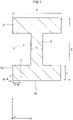
- Figure 1 is a schematic view of a cross section orthogonal to the rolling direction of the H-section steel 4.
- the H-section steel 4 has a pair of plate-like flanges 5 facing each other, and a plate-like web 6 which is formed extending orthogonally to the flanges 5 and connecting the facing surfaces of the flanges 5 at the center in the width direction.
- the X axis direction is the width direction of the flange 5
- the Y axis direction is the thickness direction of the flange 5
- the Z axis direction is the rolling direction (the longitudinal direction of the flange 5).
- a position that is separated from the end face 5a in the width direction of the flange 5 by (1/6)F (shown as F/6 in Figure 1 ), and is separated from the outer face 5b in the thickness direction of the flange 5 by (1/4)t 2 (shown as t 2 /4 in Figure 1 ) is designated as a measurement position 7.
- a plane segment orthogonal to the width direction of the flange 5 and having the measurement position 7 defined as the center thereof, is used as a plane segment for measuring the average crystal grain diameter and the MA area fraction.
- a cross section which is orthogonal to the width direction of the flange 5 (X direction) and includes one of four measurement positions 7 (intersection of F/6 and t 2 /4) existing on respective sides of the upper and lower flanges 5 of the H-section steel 4, is used as a measurement plane. More particularly, an average crystal grain diameter is measured in a region of 1 mm square, and an MA area fraction is measured in a region of 500 ⁇ m square, which include the measurement position 7 along the rolling direction as the central line in the cross section, respectively.
- an average crystal grain diameter is measured in a cross section at a position that is a distance of 1/4 of the entire length from one end of the flange in the rolling direction of the H-section steel 5 (Z direction) with respect to an optional position among the four measurement positions 7 existing on respective sides of the upper and lower flanges 5.
- the outer face 5b in the thickness direction of the flange 5 means one of the faces which are orthogonal to the thickness direction of the flange 5, which do not contact the web 6, and which are denoted by the symbol 5b in Figure 1 .
- the end face 5a in the width direction of the flange 5 means the face denoted by the symbol 5a in Figure 1 .
- the grain diameter in a steel product structure can be determined by an observation with EBSD (electron backscatter diffraction method).
- the grain diameter is an equivalent circle diameter.
- EBSD electron backscatter diffraction method
- the crystal orientation in a metal structure is observed at intervals of 0.2 ⁇ m in the region of 1 mm square orthogonal to the width direction of the flange 5, centering on the measurement position 7.
- the difference of misorientation angle being 5° or more is regarded as a grain boundary, and the average crystal grain diameter of the entire metal structure included within the grain boundaries is calculated (hereinafter simply referred to as the "average crystal grain diameter").
- this average crystal grain diameter is a weighted average value calculated by multiplying the grain diameter of each crystal by the area of the crystal grain for weighting.
- the average crystal grain diameter in the steel product structure should be 38 ⁇ m or less.
- the toughness decreases.
- the requirement of the average crystal grain diameter is an important factor for securing a favorable toughness at -20°C in a steel having a tensile strength of 490 MPa or more, which is targeted for an H-section steel of the present disclosure. The above was confirmed experimentally.
- the lower limit of the average crystal grain diameter may be, for example, 5 ⁇ m in view of manufacturability.
- the area fraction of MA in a steel product structure may be measured by etching a sample for observation cut out from the steel product with the LePera reagent, observing it with an optical microscope, and extracting MA using a known image analysis software. Specifically, in observing the sample etched with the LePera reagent, a plane segment of 500 ⁇ m square orthogonal to the width direction of the flange 5, centering on the measurement position 7 of the steel product, is photographed with an optical microscope at 200x. MA is extracted by the image analysis software "Image-Pro" from the photographed image to calculate the MA area fraction.
- the MA area fraction is measured in a cross section at a position that is a distance of 1/4 of the entire length from one end of the flange in the rolling direction of the H-section steel 5 (Z direction) with respect to an optional position out of four measurement positions 7 existing on respective sides of the upper and lower flanges 5.
- the area fraction of MA in the steel product structure is set at 1.2% or less.
- the area fraction of MA exceeds 1.2%, the toughness decreases.
- the MA area fraction is an important factor for ensuring a favorable toughness at -20°C in a steel having a tensile strength of 490 MPa or more, which is targeted for the H-section steel of the present disclosure. This was confirmed experimentally.
- the area fraction of MA is small.
- the area fraction of MA is preferably 1.0% or less, and more preferably 0.8% or less.
- the area fraction of MA may be even 0%.
- the metal structure of the steel product is preferably composed of from 0 to 10% of pearlite, from 0 to 1.2% of MA, and the balance composed of at least one of ferrite (polygonal ferrite), bainite, or acicular ferrite. It is preferable that the balance is composed of ferrite (polygonal ferrite), and at least one of bainite or acicular ferrite from the viewpoint of securing favorable strength and low temperature toughness.
- the balance includes ferrite (polygonal ferrite)
- the area fraction of the ferrite (polygonal ferrite) in the balance is not particularly limited, and may be, for example, 10 to 90%.
- a test piece for evaluating the yield strength or the 0.2% proof stress by a tensile test is a test piece cut out such that the position separated, in the width direction of the flange 5 (the X axis direction shown in Figure 1 ), from the end face 5a in the width direction of the flange 5 by (1/6)F in Figure 1 is located at the center of the width direction of the test piece.
- a tensile test is performed using this test piece.
- the test piece, of which the longitudinal direction is parallel to the rolling direction (the Z axis direction shown in Figure 1 ) may be cut out from the entire thickness direction (full thickness) of the flange 5 (the Y-axis direction shown in Figure 1 ).
- the thickness of the test piece in the width direction is within the range specified in JIS Z 2241 (2011).
- the test piece may be cut out from any position in the rolling direction insofar as the position separated in the width direction of the flange 5 from the end face 5a in the width direction of the flange 5 by (1/6)F is located at the center of the width direction of the test piece.
- the thickness t 2 of the flange 5 of the H-section steel 4 of the present disclosure is from 25 to 140 mm.
- the lower limit of the thickness t 2 is set at 25 mm, because a strength member having the thickness t 2 of the flange 5 of 25 mm or more is demanded for the H-section steel 4 used, for example, for a high-rise architectural building.
- a preferable lower limit of the thickness t 2 of the flange 5 is 40 mm.
- the upper limit of the thickness t 2 of the flange 5 is set at 140 mm, because when the thickness t 2 of the flange 5 exceeds 140 mm, the working amount at hot working is insufficient and it becomes difficult to secure both the strength and the toughness.
- the ratio of the thickness of the flange 5 to the thickness of the web 6 (t 2 /t 1 ) is preferably from 0.5 to 2.0 on the supposition of a case where an H-section steel 4 is manufactured by hot rolling.
- the ratio of the thickness of the flange 5 to the thickness of the web 6 (t 2 /t 1 ) exceeds 2.0, the web 6 may be deformed into a waving shape.
- the ratio of the thickness of the flange 5 to the thickness of the web 6 (t 2 /t 1 ) is less than 0.5, the flange 5 may be deformed into a waving shape.
- the yield strength or 0.2% proof stress at normal temperature of the test piece for evaluating the yield strength or 0.2% proof stress described above is 385 MPa or more, and the tensile strength of the same is 490 MPa or more.
- the yield strength or 0.2% proof stress means the yield strength when a yield phenomenon appears, and the 0.2% proof stress when a yield phenomenon does not appear, in a stress-strain curve.
- the yield strength is 385 MPa or more
- the 0.2% proof stress is 385 MPa or more.
- the same of the test piece 9 described above is 200 J or more.
- the yield strength or 0.2% proof stress at normal temperature is preferably 530 MPa or less, and the tensile strength is preferably 690 MPa or less.
- the normal temperature refers to herein a range of 20°C ⁇ 5°C.
- the chemical composition of a molten steel is adjusted so as to have the aforedescribed component composition, and then casting is performed to obtain a billet.
- a beam blank having a shape close to that of the H-section steel 4 to be produced may be formed.
- continuous casting is preferable.
- the thickness of the billet is preferably 200 mm or more from the viewpoint of productivity. Considering reduction in segregation, homogeneity of the heating temperature before performing hot rolling, etc., the thickness of the billet is preferably 350 mm or less.
- the lower limit of the heating temperature of the billet should be 1100°C.
- the heating temperature of the billet is lower than 1100°C, the deformation resistance becomes too high when finish rolling is performed.
- the lower limit of the heating temperature of the billet is preferably 1150°C.
- the upper limit of the heating temperature of the billet should be 1350°C.
- the hot rolling may be carried out, for example, as shown in Figure 3 , in which after the intermediate rolling with the cumulative reduction rate A, the finish rolling with the cumulative reduction rate B is performed.
- a cumulative reduction rate A or B means herein the difference between the flange thickness before rolling and the flange thickness after rolling divided by the flange thickness before rolling.
- the ferrite transformation may start before accelerated cooling starts, which may lower YS or TS. Therefore, the lower limit of the temperature of the finish rolling is 750°C in terms of the surface temperature.
- the difference in cooling rate may increase in a cross section of the steel product occasionally (particularly between the position separated, in the width direction of the flange 5 from the end face 5a in the width direction of the flange 5 by (1/6)F, and separated, in the thickness direction of the flange 5 from the outer face 5b in the thickness direction of the flange by (1/4)t 2 and the position separated, in the width direction of the flange 5 from the end face 5b in the width direction of the flange 5 by (1/6)F, and separated, in the thickness direction of the flange 5 from the outer face 5b in the thickness direction of the flange by (1/2)t 2 in the cross section) to cause a large difference in the mechanical characteristics.
- the average cooling rate is preferably regulated to 2.0°C/s or less.
- the regulation of the average cooling rate to 2.0°C/s or less is merely an example of a preferred embodiment, and there is no particular restriction on the upper limit of the average cooling rate.
- the accelerated cooling is carried out until the recalescence temperature after the termination of the accelerated cooling of the surface becomes 600°C or lower at the position separated, from the end face 5a in the width direction of the flange 5 by (1/6)F.
- the yield strength or 0.2% proof stress of is 385 MPa or more, and the tensile strength is 490 MPa or more in the aforedescribed tensile test; as well as the Charpy absorbed energy at -20°C in the aforedescribed test piece 9 is 200 J or more. Therefore, the H-section steel 4 produced is a high-strength extra-heavy H-section steel 4 having an excellent low temperature toughness.
- the method of producing an H-section steel 4 of the present disclosure does not require a sophisticated steelmaking technology or accelerated cooling, and is capable of reducing the production load, and shortening the process time. Therefore, industrial contribution, such as improvement of the reliability of a large building without impairing economic efficiency, is extremely remarkable.
- H-section steel of the present disclosure will be specifically described below based on Examples, provided that the H-section steel of the present disclosure is not limited to the Examples.
- Each steel having one of the compositions shown in Table 1 and Table 2 was melted, and a billet having a thickness of from 240 to 300 mm was produced by continuous casting.
- the steel was melted in a converter, and after primary deoxidation alloying elements were added to adjust the ingredients, and vacuum degassing was performed according to need.
- the billet thus obtained was heated and subjected to hot rolling to produce an H-section steel 4.
- the ingredients shown in Table 1 and Table 2 were obtained by a chemical analysis of a sample taken from each H-section steel 4 after production. [Table 1] Composition No.
- a blank cell means that the relevant element is not intentionally added.
- the underlined numerical value means that it is out of the scope of the H-section steel of the present disclosure.
- the contents of the elements of P, S, and O (oxygen) were respectively P: 0.03% or less, S: 0.02% or less, and O: 0.005% or less.
- FIG. 3 The production process of an H-section steel 4 is shown in Figure 3 .
- a billet heated in the heating furnace 1 was processed in a universal rolling mill line including a rough rolling mill 2a, an intermediate rolling mill 2b, and a finish rolling mill 2c.
- accelerated cooling was applied, either continuously or intermittently with periods of air-cooling.
- water coolers 3 placed before and after the intermediate universal rolling machine (intermediate rolling mill 2 b) were used to perform spray cooling of the outer faces of flanges and reversing rolling.
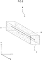
- a Charpy test piece (see Figure 2 ), which was cut out such that its longitudinal direction was parallel to the rolling direction, centering on the measurement position 7, a Charpy test was conducted at -20°C to evaluate the low temperature toughness. Further, as described above, designating the length in the width direction of the flange 5 as F, a test piece was cut out from the H-section steel 4 such that the position separated, in the width direction of the flange 5 (the X axis direction in Figure 1 ), from the end face 5a in the width direction of the flange 5 by (1/6)F is located at the center in the thickness direction, and a tensile test in the rolling direction of the flange 5 was performed using the test piece.
- the tensile test was carried out in accordance with JIS Z 2241 (2011), and a yield point was determined in a case where a yielding behavior appeared, and a 0.2% proof stress was determined in a case where a yielding behavior did not appear, and they were regarded as YS.
- the test piece for the tensile test was JIS Type 1A, and the measurement temperature was 20°C ⁇ 5°C.
- the Charpy impact test was carried out at -20°C in accordance with JIS Z 2242 (2005).
- the target values of the mechanical characteristics were set for a yield strength or a 0.2% proof stress (YS) at normal temperature at 385 MPa or more, and for a tensile strength (TS) at 490 MPa or more.
- the target value of Charpy absorbed energy (vE -20 ) at -20°C is 200 J or more.
- the notch shape in the Charpy test was V notch, and the notch depth was 2 mm.
- the heating temperature of a billet during production, the production conditions such as hot rolling, the average crystal grain diameter, the MA area fraction, the yield strength or 0.2% proof stress (YS), the tensile strength (TS), and the absorbed energy in a Charpy test at -20°C (vE -20 ) are shown in Tables 3 to 6.
- the reduction rate in performing hot rolling according to Table 3 or 5 is the rolling reduction rate at the position separated, in the width direction of the flange 5 (the X axis direction in Figure 1 ) from the end face 5a in the width direction of the flange 5 by (1/6)F.
- the average cooling rate at the measurement position 7 was calculated by computer simulation from the actual values of the flange thickness t 2 of the H-section steel 4, the water cooling start temperature, and the recalescence temperature.
- the metal structure of each Example was composed of 10% or less of perlite, 1.2% of MA, and the balance, which was composed of ferrite (polygonal ferrite), and at least one of bainite or acicular ferrite.
Landscapes
- Chemical & Material Sciences (AREA)
- Engineering & Computer Science (AREA)
- Materials Engineering (AREA)
- Mechanical Engineering (AREA)
- Metallurgy (AREA)
- Organic Chemistry (AREA)
- Architecture (AREA)
- Thermal Sciences (AREA)
- Crystallography & Structural Chemistry (AREA)
- Physics & Mathematics (AREA)
- Civil Engineering (AREA)
- Structural Engineering (AREA)
- Heat Treatment Of Steel (AREA)
- Metal Rolling (AREA)
Claims (3)
- Ein H-Profilstahl mit einer Komponentenzusammensetzung umfassend, in Massen-%:C: von 0,040 bis 0,100%,Mn: von 0,50 bis 1,70%,Cu: von 0,01 bis 0,50%,Ni: von 0,01 bis 0,50%,Cr: von 0,01 bis 0,50%,Nb: von 0,001 bis 0,050%,V: von 0,010 bis 0,120%,Al: von 0,005 bis 0,100%,Ti: von 0,001 bis 0,025%B: von mehr als 0,0005 bis 0,0020%,N: von 0,0001 bis 0,0120%,P: 0,03% oder weniger,S: 0,02% oder weniger,O: 0,005% oder weniger,Si: von 0 bis 0,08%,Mo: von 0 bis 0,20%,W: von 0 bis 0,50%,Ca: von 0 bis 0,0050%,Zr: von 0 bis 0,0050%,Mg: von 0 bis 0,0050%,REM: von 0 bis 0,005% undFe und Verunreinigungen: der Rest, wobei P, S und O Verunreinigungen sind, wobei:ein durch die folgende Formel (1) bestimmtes Kohlenstoffäquivalent Ceq 0,300 bis 0,480 beträgt,eine Dicke eines Flansch 25 bis 140 mm beträgt,ein mittlerer Kristallkorndurchmesser in einer Ebene orthogonal zu einer Breitenrichtung des Flansches 38 µm oder weniger beträgt, zentriert auf eine Messposition, die eine Position ist, die in der Breitenrichtung des Flansches von einer Endfläche in der Breitenrichtung des Flansches um (1/6)F beabstandet ist und in einer Dickenrichtung des Flansches von einer Außenfläche in der Dickenrichtung des Flansches um (1/4)t2 beabstandet ist, wenn eine Breitenrichtungslänge des Flansches gleich F ist und eine Dicke des Flansches gleich t2 ist,ein Flächenanteil eines Martensit-Austenit-Konstituenten (MA) in einer Stahlproduktstruktur in der Ebene orthogonal zur Breitenrichtung des Flansches 1,2% oder weniger beträgt, zentriert auf die Messposition und gemessen nach dem in der Beschreibung angegebenen Verfahren,eine Streckgrenze oder eine 0,2%-Dehngrenze 385 MPa oder mehr beträgt und eine Zugfestigkeit 490 MPa oder mehr beträgt, in einer Walzrichtung des Flansches, wenn sie in Bezug auf eine gesamte Dicke in Dickenrichtung des Flansches an einer Position gemessen wird, die in der Breitenrichtung des Flansches von der Endfläche in der Breitenrichtung des Flansches um (1/6)F beabstandet ist, wobei die Streckgrenze oder0,2%-Dehngrenze und die Zugfestigkeit nach JIS Z 2241 2011 gemessen werden, undeine absorbierte Energie in einem Charpy-Test an der Messposition bei -20°C 200 J odermehr beträgt, gemessen nach JIS Z 2242 2005, in der Walzrichtung und wobei die Kerbrichtung in der Breitenrichtung des Flansches liegt:
Formel (1) Ceq = C + Mn/6 + (Cr + Mo + V)/5 + (Ni + Cu)/15
wobei, in Formel (1), C, Mn, Cr, Mo, V, Ni und Cu die jeweiligen Gehalte in Massen-% jedes Elements darstellen und 0 für ein Element steht, das nicht enthalten ist, undwobei der mittlere Kristallkorndurchmesser gemäß der Beschreibung bestimmt wird. - Ein Verfahren zur Herstellung des H-Profilstahls nach Anspruch 1, wobei das Verfahren umfasst:einen Schritt des Erwärmens eines Stranges mit der Komponentenzusammensetzung nach Anspruch 1 auf eine Temperatur im Bereich von 1100 bis 1350°C;einen Schritt des Walzens, der nach dem Schritt des Erwärmens eingeleitet wird, wobei das Walzen durchgeführt wird, um eine solche Reduktion zu induzieren, dass an einer Position, die in einer Breitenrichtung eines Flansches von einer Endfläche in der Breitenrichtung des Flansches durch (1/6)F beabstandet ist, ein kumulatives Reduktionsverhältnis A in einem Bereich der Oberflächentemperatur von 900°C bis 1100°C mehr als 10% beträgt, und ein kumulatives Reduktionsverhältnis B in einem Bereich von 750°C bis weniger als 900°C 10% oder mehr beträgt, und das Walzen beendet wird, wenn eine Oberflächentemperatur 750°C oder mehr beträgt und eine Dicke des Flansches in einem Bereich von 25 bis 140 mm ausgebildet ist, bedeutet das kumulative Reduktionsverhältnis A oder B die Differenz zwischen der Flanschdicke vor dem Walzen und der Flanschdicke nach dem Walzen geteilt durch die Flanschdicke vor dem Walzen; undeinen Schritt des Durchführens einer beschleunigten Abkühlung nach dem Schritt des Walzens, entweder kontinuierlich oder intermittierend mit Perioden der Luftabkühlung, mit einer mittleren Abkühlungsgeschwindigkeit von 0,4°C/s oder mehr an der Position, die in der Breitenrichtung des Flansches von der Endfläche in der Breitenrichtung des Flansches durch (1/6)F beabstandet ist und in einer Dickenrichtung des Flansches von der Außenfläche in der Dickenrichtung des Flansches durch (1/4)t2 beabstandet ist, wobei die Länge des Flansches in der Breitenrichtung F ist und die Dicke des Flansches t2 ist.
- Das Verfahren zur Herstellung eines H-Profilstahls nach Anspruch 2, wobei die beschleunigte Abkühlung so durchgeführt wird, dass die Rekaleszenztemperatur nach Beendigung der Abkühlung an der Position, die in Breitenrichtung des Flansches von der Endfläche in Breitenrichtung des Flansches um (1/6)F beabstandet ist, 600°C oder weniger beträgt.
Applications Claiming Priority (2)
| Application Number | Priority Date | Filing Date | Title |
|---|---|---|---|
| JP2017049844 | 2017-03-15 | ||
| PCT/JP2018/010339 WO2018169020A1 (ja) | 2017-03-15 | 2018-03-15 | H形鋼およびその製造方法 |
Publications (3)
| Publication Number | Publication Date |
|---|---|
| EP3597783A1 EP3597783A1 (de) | 2020-01-22 |
| EP3597783A4 EP3597783A4 (de) | 2020-11-04 |
| EP3597783B1 true EP3597783B1 (de) | 2022-06-08 |
Family
ID=63523905
Family Applications (1)
| Application Number | Title | Priority Date | Filing Date |
|---|---|---|---|
| EP18766786.0A Active EP3597783B1 (de) | 2017-03-15 | 2018-03-15 | H-profil-stahl und verfahren zu seiner herstellung |
Country Status (7)
| Country | Link |
|---|---|
| US (1) | US11041231B2 (de) |
| EP (1) | EP3597783B1 (de) |
| JP (1) | JP6787479B2 (de) |
| CN (1) | CN110291218B (de) |
| CA (1) | CA3054279A1 (de) |
| SG (1) | SG11201907436YA (de) |
| WO (1) | WO2018169020A1 (de) |
Families Citing this family (7)
| Publication number | Priority date | Publication date | Assignee | Title |
|---|---|---|---|---|
| JP6819830B2 (ja) * | 2019-01-31 | 2021-01-27 | Jfeスチール株式会社 | 突起付きh形鋼およびその製造方法 |
| JP7440757B2 (ja) * | 2020-03-27 | 2024-02-29 | 日本製鉄株式会社 | H形鋼およびその製造方法 |
| CN111733368A (zh) * | 2020-07-10 | 2020-10-02 | 武钢集团昆明钢铁股份有限公司 | 一种隧道支护用高强度抗震工字钢及其制备方法 |
| CN112458364B (zh) | 2020-11-04 | 2021-09-03 | 马鞍山钢铁股份有限公司 | 一种超厚规格热轧h型钢及其生产方法 |
| JP7405246B2 (ja) * | 2021-03-03 | 2023-12-26 | Jfeスチール株式会社 | H形鋼 |
| CN113604735B (zh) * | 2021-07-20 | 2022-07-12 | 山东钢铁股份有限公司 | 一种屈服强度420MPa级热轧耐低温H型钢及其制备方法 |
| JP7661934B2 (ja) * | 2022-06-07 | 2025-04-15 | Jfeスチール株式会社 | 鋼矢板及びその製造方法 |
Family Cites Families (18)
| Publication number | Priority date | Publication date | Assignee | Title |
|---|---|---|---|---|
| JP3410241B2 (ja) | 1995-01-23 | 2003-05-26 | 川崎製鉄株式会社 | 強度、靭性及び溶接性に優れた極厚h形鋼の製造方法 |
| US5858130A (en) * | 1997-06-25 | 1999-01-12 | Bethlehem Steel Corporation | Composition and method for producing an alloy steel and a product therefrom for structural applications |
| JP3589071B2 (ja) | 1998-03-24 | 2004-11-17 | 住友金属工業株式会社 | 溶接性、強度および靱性に優れた極厚形鋼の製造法 |
| TW541342B (en) | 2000-04-04 | 2003-07-11 | Nippon Steel Corp | Hot rolled h-shap steel having an uniform microstruture and mechanical properties |
| JP3736495B2 (ja) | 2002-05-14 | 2006-01-18 | 住友金属工業株式会社 | 極厚鋼材の製造方法 |
| JP4276576B2 (ja) | 2004-04-20 | 2009-06-10 | 新日本製鐵株式会社 | 大入熱溶接熱影響部靭性に優れた厚手高強度鋼板 |
| JP2006063443A (ja) * | 2004-07-28 | 2006-03-09 | Nippon Steel Corp | 耐火性に優れたh形鋼およびその製造方法 |
| JP4696602B2 (ja) | 2005-03-09 | 2011-06-08 | Jfeスチール株式会社 | 低温靭性に優れる圧延h形鋼の製造方法 |
| JP3960341B2 (ja) | 2005-05-17 | 2007-08-15 | 住友金属工業株式会社 | 熱加工制御型590MPa級H形鋼及びその製造方法 |
| JP5176885B2 (ja) | 2008-11-10 | 2013-04-03 | 新日鐵住金株式会社 | 鋼材及びその製造方法 |
| BR112012019769B1 (pt) * | 2010-02-08 | 2018-05-02 | Nippon Steel & Sumitomo Metal Corporation | Método de produção de placa de aço. |
| US9644372B2 (en) | 2011-12-15 | 2017-05-09 | Nippon Steel & Sumitomo Metal Corporation | High-strength H-beam steel exhibiting excellent low-temperature toughness and method of manufacturing same |
| CN102605243B (zh) * | 2012-03-15 | 2013-12-25 | 莱芜钢铁集团有限公司 | 风电用h型钢及其生产方法 |
| JP5655984B2 (ja) * | 2012-11-26 | 2015-01-21 | 新日鐵住金株式会社 | H形鋼及びその製造方法 |
| CN104018073B (zh) * | 2014-06-19 | 2015-11-18 | 马钢(集团)控股有限公司 | 一种耐低温韧性h型钢及其生产工艺 |
| JP6354572B2 (ja) * | 2014-10-27 | 2018-07-11 | 新日鐵住金株式会社 | 低温用h形鋼及びその製造方法 |
| JP6409598B2 (ja) * | 2015-01-30 | 2018-10-24 | 新日鐵住金株式会社 | 靭性に優れた高強度極厚h形鋼及びその製造方法 |
| JP6662592B2 (ja) | 2015-09-02 | 2020-03-11 | 株式会社らかんスタジオ | 画像処理システム及び画像処理システム用センタサーバ |
-
2018
- 2018-03-15 US US16/488,810 patent/US11041231B2/en active Active
- 2018-03-15 SG SG11201907436YA patent/SG11201907436YA/en unknown
- 2018-03-15 EP EP18766786.0A patent/EP3597783B1/de active Active
- 2018-03-15 CN CN201880011844.2A patent/CN110291218B/zh active Active
- 2018-03-15 CA CA3054279A patent/CA3054279A1/en not_active Abandoned
- 2018-03-15 WO PCT/JP2018/010339 patent/WO2018169020A1/ja not_active Ceased
- 2018-03-15 JP JP2019506276A patent/JP6787479B2/ja active Active
Also Published As
| Publication number | Publication date |
|---|---|
| WO2018169020A1 (ja) | 2018-09-20 |
| EP3597783A1 (de) | 2020-01-22 |
| CA3054279A1 (en) | 2018-09-20 |
| US20210140024A1 (en) | 2021-05-13 |
| JPWO2018169020A1 (ja) | 2019-12-12 |
| JP6787479B2 (ja) | 2020-11-18 |
| CN110291218B (zh) | 2021-06-22 |
| SG11201907436YA (en) | 2019-09-27 |
| EP3597783A4 (de) | 2020-11-04 |
| US11041231B2 (en) | 2021-06-22 |
| CN110291218A (zh) | 2019-09-27 |
Similar Documents
| Publication | Publication Date | Title |
|---|---|---|
| EP3597783B1 (de) | H-profil-stahl und verfahren zu seiner herstellung | |
| EP2949772B1 (de) | Heissgewalztes stahlblech und verfahren zur herstellung davon | |
| EP1662014B1 (de) | Stahlpatte und geschweisstes stahlrohr mit kleinem streckgrenzenverhältnis und hoher zähigkeit und herstellungsverfahren dafür | |
| EP3085803B1 (de) | H-förmiger stahl und verfahren zur herstellung davon | |
| CN109715842B (zh) | H型钢及其制造方法 | |
| EP3409803B1 (de) | Hochfestes warmgewalztes stahlblech für elektrisches widerstandsgeschweisstes stahlrohr und herstellungsverfahren dafür | |
| EP2975149B1 (de) | H-förmiger stahl und verfahren zur herstellung davon | |
| EP2792761B1 (de) | Extradicker hochfester doppel-t-stahlträger | |
| KR101883588B1 (ko) | H형강 및 그 제조 방법 | |
| EP2759615A1 (de) | Hochfestes warmgewalztes stahlblech mit hervorragenden biegungseigenschaften und tieftemperaturbeständigkeit sowie herstellungsverfahren dafür | |
| WO2018151273A1 (ja) | 熱間圧延鋼板及びその製造方法 | |
| WO2024203266A1 (ja) | 鋼板及びその製造方法 | |
| JP6988836B2 (ja) | 超低降伏比高張力厚鋼板およびその製造方法 | |
| WO2020170775A1 (ja) | 角形鋼管およびその製造方法並びに建築構造物 | |
| JP7393614B2 (ja) | 高強度高延性鋼板及びその製造方法 | |
| WO2019180957A1 (ja) | 圧延h形鋼及びその製造方法 | |
| JP2023031269A (ja) | 超低降伏比高張力厚鋼板およびその製造方法 | |
| JP7440757B2 (ja) | H形鋼およびその製造方法 | |
| KR102412013B1 (ko) | 열연 강판 | |
| JP6295632B2 (ja) | 靭性に優れた高強度h形鋼 | |
| JP2025124214A (ja) | H形鋼およびその製造方法 | |
| WO2023053829A1 (ja) | 鋼板 | |
| JP2002249853A (ja) | フレーム用フェライト系ステンレス鋼材およびその製造方法 | |
| EP3476969A1 (de) | Ausscheidungshärtendes warmgewalztes stahlblech mit ausgezeichneter materialgleichmässigkeit und lochdehnbarkeit und herstellungsverfahren dafür |
Legal Events
| Date | Code | Title | Description |
|---|---|---|---|
| STAA | Information on the status of an ep patent application or granted ep patent |
Free format text: STATUS: THE INTERNATIONAL PUBLICATION HAS BEEN MADE |
|
| PUAI | Public reference made under article 153(3) epc to a published international application that has entered the european phase |
Free format text: ORIGINAL CODE: 0009012 |
|
| STAA | Information on the status of an ep patent application or granted ep patent |
Free format text: STATUS: REQUEST FOR EXAMINATION WAS MADE |
|
| 17P | Request for examination filed |
Effective date: 20190902 |
|
| AK | Designated contracting states |
Kind code of ref document: A1 Designated state(s): AL AT BE BG CH CY CZ DE DK EE ES FI FR GB GR HR HU IE IS IT LI LT LU LV MC MK MT NL NO PL PT RO RS SE SI SK SM TR |
|
| AX | Request for extension of the european patent |
Extension state: BA ME |
|
| DAV | Request for validation of the european patent (deleted) | ||
| DAX | Request for extension of the european patent (deleted) | ||
| A4 | Supplementary search report drawn up and despatched |
Effective date: 20201001 |
|
| RIC1 | Information provided on ipc code assigned before grant |
Ipc: C21D 8/02 20060101ALI20200925BHEP Ipc: B21B 1/088 20060101ALI20200925BHEP Ipc: C22C 38/44 20060101ALI20200925BHEP Ipc: C22C 38/38 20060101ALI20200925BHEP Ipc: C22C 38/46 20060101ALI20200925BHEP Ipc: C22C 38/58 20060101ALI20200925BHEP Ipc: C21D 8/00 20060101ALI20200925BHEP Ipc: C22C 38/54 20060101ALI20200925BHEP Ipc: E02D 5/04 20060101ALI20200925BHEP Ipc: C22C 38/50 20060101ALI20200925BHEP Ipc: C22C 38/04 20060101ALI20200925BHEP Ipc: C22C 38/48 20060101ALI20200925BHEP Ipc: E04C 3/04 20060101ALN20200925BHEP Ipc: E04C 3/06 20060101ALI20200925BHEP Ipc: C22C 38/42 20060101ALI20200925BHEP Ipc: C22C 38/00 20060101AFI20200925BHEP |
|
| RIC1 | Information provided on ipc code assigned before grant |
Ipc: E04C 3/04 20060101ALN20210702BHEP Ipc: E04C 3/06 20060101ALI20210702BHEP Ipc: E02D 5/04 20060101ALI20210702BHEP Ipc: C22C 38/54 20060101ALI20210702BHEP Ipc: C22C 38/50 20060101ALI20210702BHEP Ipc: C22C 38/48 20060101ALI20210702BHEP Ipc: C22C 38/46 20060101ALI20210702BHEP Ipc: C22C 38/44 20060101ALI20210702BHEP Ipc: C22C 38/42 20060101ALI20210702BHEP Ipc: C22C 38/38 20060101ALI20210702BHEP Ipc: C22C 38/04 20060101ALI20210702BHEP Ipc: C21D 8/02 20060101ALI20210702BHEP Ipc: C22C 38/58 20060101ALI20210702BHEP Ipc: C21D 8/00 20060101ALI20210702BHEP Ipc: B21B 1/088 20060101ALI20210702BHEP Ipc: C22C 38/00 20060101AFI20210702BHEP |
|
| GRAP | Despatch of communication of intention to grant a patent |
Free format text: ORIGINAL CODE: EPIDOSNIGR1 |
|
| STAA | Information on the status of an ep patent application or granted ep patent |
Free format text: STATUS: GRANT OF PATENT IS INTENDED |
|
| RIC1 | Information provided on ipc code assigned before grant |
Ipc: E04C 3/04 20060101ALN20210728BHEP Ipc: E04C 3/06 20060101ALI20210728BHEP Ipc: E02D 5/04 20060101ALI20210728BHEP Ipc: C22C 38/54 20060101ALI20210728BHEP Ipc: C22C 38/50 20060101ALI20210728BHEP Ipc: C22C 38/48 20060101ALI20210728BHEP Ipc: C22C 38/46 20060101ALI20210728BHEP Ipc: C22C 38/44 20060101ALI20210728BHEP Ipc: C22C 38/42 20060101ALI20210728BHEP Ipc: C22C 38/38 20060101ALI20210728BHEP Ipc: C22C 38/04 20060101ALI20210728BHEP Ipc: C21D 8/02 20060101ALI20210728BHEP Ipc: C22C 38/58 20060101ALI20210728BHEP Ipc: C21D 8/00 20060101ALI20210728BHEP Ipc: B21B 1/088 20060101ALI20210728BHEP Ipc: C22C 38/00 20060101AFI20210728BHEP |
|
| INTG | Intention to grant announced |
Effective date: 20210831 |
|
| GRAJ | Information related to disapproval of communication of intention to grant by the applicant or resumption of examination proceedings by the epo deleted |
Free format text: ORIGINAL CODE: EPIDOSDIGR1 |
|
| STAA | Information on the status of an ep patent application or granted ep patent |
Free format text: STATUS: REQUEST FOR EXAMINATION WAS MADE |
|
| GRAP | Despatch of communication of intention to grant a patent |
Free format text: ORIGINAL CODE: EPIDOSNIGR1 |
|
| STAA | Information on the status of an ep patent application or granted ep patent |
Free format text: STATUS: GRANT OF PATENT IS INTENDED |
|
| INTC | Intention to grant announced (deleted) | ||
| RIC1 | Information provided on ipc code assigned before grant |
Ipc: E04C 3/04 20060101ALN20211117BHEP Ipc: E04C 3/06 20060101ALI20211117BHEP Ipc: E02D 5/04 20060101ALI20211117BHEP Ipc: C22C 38/54 20060101ALI20211117BHEP Ipc: C22C 38/50 20060101ALI20211117BHEP Ipc: C22C 38/48 20060101ALI20211117BHEP Ipc: C22C 38/46 20060101ALI20211117BHEP Ipc: C22C 38/44 20060101ALI20211117BHEP Ipc: C22C 38/42 20060101ALI20211117BHEP Ipc: C22C 38/38 20060101ALI20211117BHEP Ipc: C22C 38/04 20060101ALI20211117BHEP Ipc: C21D 8/02 20060101ALI20211117BHEP Ipc: C22C 38/58 20060101ALI20211117BHEP Ipc: C21D 8/00 20060101ALI20211117BHEP Ipc: B21B 1/088 20060101ALI20211117BHEP Ipc: C22C 38/00 20060101AFI20211117BHEP |
|
| INTG | Intention to grant announced |
Effective date: 20211215 |
|
| GRAS | Grant fee paid |
Free format text: ORIGINAL CODE: EPIDOSNIGR3 |
|
| GRAA | (expected) grant |
Free format text: ORIGINAL CODE: 0009210 |
|
| STAA | Information on the status of an ep patent application or granted ep patent |
Free format text: STATUS: THE PATENT HAS BEEN GRANTED |
|
| AK | Designated contracting states |
Kind code of ref document: B1 Designated state(s): AL AT BE BG CH CY CZ DE DK EE ES FI FR GB GR HR HU IE IS IT LI LT LU LV MC MK MT NL NO PL PT RO RS SE SI SK SM TR |
|
| REG | Reference to a national code |
Ref country code: AT Ref legal event code: REF Ref document number: 1496969 Country of ref document: AT Kind code of ref document: T Effective date: 20220615 Ref country code: CH Ref legal event code: EP |
|
| REG | Reference to a national code |
Ref country code: DE Ref legal event code: R096 Ref document number: 602018036539 Country of ref document: DE |
|
| REG | Reference to a national code |
Ref country code: IE Ref legal event code: FG4D |
|
| REG | Reference to a national code |
Ref country code: LT Ref legal event code: MG9D |
|
| REG | Reference to a national code |
Ref country code: NL Ref legal event code: MP Effective date: 20220608 |
|
| PG25 | Lapsed in a contracting state [announced via postgrant information from national office to epo] |
Ref country code: SE Free format text: LAPSE BECAUSE OF FAILURE TO SUBMIT A TRANSLATION OF THE DESCRIPTION OR TO PAY THE FEE WITHIN THE PRESCRIBED TIME-LIMIT Effective date: 20220608 Ref country code: NO Free format text: LAPSE BECAUSE OF FAILURE TO SUBMIT A TRANSLATION OF THE DESCRIPTION OR TO PAY THE FEE WITHIN THE PRESCRIBED TIME-LIMIT Effective date: 20220908 Ref country code: LT Free format text: LAPSE BECAUSE OF FAILURE TO SUBMIT A TRANSLATION OF THE DESCRIPTION OR TO PAY THE FEE WITHIN THE PRESCRIBED TIME-LIMIT Effective date: 20220608 Ref country code: HR Free format text: LAPSE BECAUSE OF FAILURE TO SUBMIT A TRANSLATION OF THE DESCRIPTION OR TO PAY THE FEE WITHIN THE PRESCRIBED TIME-LIMIT Effective date: 20220608 Ref country code: GR Free format text: LAPSE BECAUSE OF FAILURE TO SUBMIT A TRANSLATION OF THE DESCRIPTION OR TO PAY THE FEE WITHIN THE PRESCRIBED TIME-LIMIT Effective date: 20220909 Ref country code: FI Free format text: LAPSE BECAUSE OF FAILURE TO SUBMIT A TRANSLATION OF THE DESCRIPTION OR TO PAY THE FEE WITHIN THE PRESCRIBED TIME-LIMIT Effective date: 20220608 Ref country code: ES Free format text: LAPSE BECAUSE OF FAILURE TO SUBMIT A TRANSLATION OF THE DESCRIPTION OR TO PAY THE FEE WITHIN THE PRESCRIBED TIME-LIMIT Effective date: 20220608 Ref country code: BG Free format text: LAPSE BECAUSE OF FAILURE TO SUBMIT A TRANSLATION OF THE DESCRIPTION OR TO PAY THE FEE WITHIN THE PRESCRIBED TIME-LIMIT Effective date: 20220908 |
|
| REG | Reference to a national code |
Ref country code: AT Ref legal event code: MK05 Ref document number: 1496969 Country of ref document: AT Kind code of ref document: T Effective date: 20220608 |
|
| PG25 | Lapsed in a contracting state [announced via postgrant information from national office to epo] |
Ref country code: RS Free format text: LAPSE BECAUSE OF FAILURE TO SUBMIT A TRANSLATION OF THE DESCRIPTION OR TO PAY THE FEE WITHIN THE PRESCRIBED TIME-LIMIT Effective date: 20220608 Ref country code: LV Free format text: LAPSE BECAUSE OF FAILURE TO SUBMIT A TRANSLATION OF THE DESCRIPTION OR TO PAY THE FEE WITHIN THE PRESCRIBED TIME-LIMIT Effective date: 20220608 |
|
| PG25 | Lapsed in a contracting state [announced via postgrant information from national office to epo] |
Ref country code: NL Free format text: LAPSE BECAUSE OF FAILURE TO SUBMIT A TRANSLATION OF THE DESCRIPTION OR TO PAY THE FEE WITHIN THE PRESCRIBED TIME-LIMIT Effective date: 20220608 |
|
| PG25 | Lapsed in a contracting state [announced via postgrant information from national office to epo] |
Ref country code: SM Free format text: LAPSE BECAUSE OF FAILURE TO SUBMIT A TRANSLATION OF THE DESCRIPTION OR TO PAY THE FEE WITHIN THE PRESCRIBED TIME-LIMIT Effective date: 20220608 Ref country code: SK Free format text: LAPSE BECAUSE OF FAILURE TO SUBMIT A TRANSLATION OF THE DESCRIPTION OR TO PAY THE FEE WITHIN THE PRESCRIBED TIME-LIMIT Effective date: 20220608 Ref country code: RO Free format text: LAPSE BECAUSE OF FAILURE TO SUBMIT A TRANSLATION OF THE DESCRIPTION OR TO PAY THE FEE WITHIN THE PRESCRIBED TIME-LIMIT Effective date: 20220608 Ref country code: PT Free format text: LAPSE BECAUSE OF FAILURE TO SUBMIT A TRANSLATION OF THE DESCRIPTION OR TO PAY THE FEE WITHIN THE PRESCRIBED TIME-LIMIT Effective date: 20221010 Ref country code: EE Free format text: LAPSE BECAUSE OF FAILURE TO SUBMIT A TRANSLATION OF THE DESCRIPTION OR TO PAY THE FEE WITHIN THE PRESCRIBED TIME-LIMIT Effective date: 20220608 Ref country code: CZ Free format text: LAPSE BECAUSE OF FAILURE TO SUBMIT A TRANSLATION OF THE DESCRIPTION OR TO PAY THE FEE WITHIN THE PRESCRIBED TIME-LIMIT Effective date: 20220608 Ref country code: AT Free format text: LAPSE BECAUSE OF FAILURE TO SUBMIT A TRANSLATION OF THE DESCRIPTION OR TO PAY THE FEE WITHIN THE PRESCRIBED TIME-LIMIT Effective date: 20220608 |
|
| PG25 | Lapsed in a contracting state [announced via postgrant information from national office to epo] |
Ref country code: PL Free format text: LAPSE BECAUSE OF FAILURE TO SUBMIT A TRANSLATION OF THE DESCRIPTION OR TO PAY THE FEE WITHIN THE PRESCRIBED TIME-LIMIT Effective date: 20220608 Ref country code: IS Free format text: LAPSE BECAUSE OF FAILURE TO SUBMIT A TRANSLATION OF THE DESCRIPTION OR TO PAY THE FEE WITHIN THE PRESCRIBED TIME-LIMIT Effective date: 20221008 |
|
| REG | Reference to a national code |
Ref country code: DE Ref legal event code: R097 Ref document number: 602018036539 Country of ref document: DE |
|
| PG25 | Lapsed in a contracting state [announced via postgrant information from national office to epo] |
Ref country code: AL Free format text: LAPSE BECAUSE OF FAILURE TO SUBMIT A TRANSLATION OF THE DESCRIPTION OR TO PAY THE FEE WITHIN THE PRESCRIBED TIME-LIMIT Effective date: 20220608 |
|
| PLBE | No opposition filed within time limit |
Free format text: ORIGINAL CODE: 0009261 |
|
| STAA | Information on the status of an ep patent application or granted ep patent |
Free format text: STATUS: NO OPPOSITION FILED WITHIN TIME LIMIT |
|
| PG25 | Lapsed in a contracting state [announced via postgrant information from national office to epo] |
Ref country code: DK Free format text: LAPSE BECAUSE OF FAILURE TO SUBMIT A TRANSLATION OF THE DESCRIPTION OR TO PAY THE FEE WITHIN THE PRESCRIBED TIME-LIMIT Effective date: 20220608 |
|
| 26N | No opposition filed |
Effective date: 20230310 |
|
| PG25 | Lapsed in a contracting state [announced via postgrant information from national office to epo] |
Ref country code: SI Free format text: LAPSE BECAUSE OF FAILURE TO SUBMIT A TRANSLATION OF THE DESCRIPTION OR TO PAY THE FEE WITHIN THE PRESCRIBED TIME-LIMIT Effective date: 20220608 |
|
| REG | Reference to a national code |
Ref country code: DE Ref legal event code: R119 Ref document number: 602018036539 Country of ref document: DE |
|
| PG25 | Lapsed in a contracting state [announced via postgrant information from national office to epo] |
Ref country code: MC Free format text: LAPSE BECAUSE OF FAILURE TO SUBMIT A TRANSLATION OF THE DESCRIPTION OR TO PAY THE FEE WITHIN THE PRESCRIBED TIME-LIMIT Effective date: 20220608 |
|
| REG | Reference to a national code |
Ref country code: CH Ref legal event code: PL |
|
| GBPC | Gb: european patent ceased through non-payment of renewal fee |
Effective date: 20230315 |
|
| REG | Reference to a national code |
Ref country code: BE Ref legal event code: MM Effective date: 20230331 |
|
| REG | Reference to a national code |
Ref country code: IE Ref legal event code: MM4A |
|
| PG25 | Lapsed in a contracting state [announced via postgrant information from national office to epo] |
Ref country code: GB Free format text: LAPSE BECAUSE OF NON-PAYMENT OF DUE FEES Effective date: 20230315 |
|
| PG25 | Lapsed in a contracting state [announced via postgrant information from national office to epo] |
Ref country code: LI Free format text: LAPSE BECAUSE OF NON-PAYMENT OF DUE FEES Effective date: 20230331 Ref country code: IT Free format text: LAPSE BECAUSE OF FAILURE TO SUBMIT A TRANSLATION OF THE DESCRIPTION OR TO PAY THE FEE WITHIN THE PRESCRIBED TIME-LIMIT Effective date: 20220608 Ref country code: IE Free format text: LAPSE BECAUSE OF NON-PAYMENT OF DUE FEES Effective date: 20230315 Ref country code: GB Free format text: LAPSE BECAUSE OF NON-PAYMENT OF DUE FEES Effective date: 20230315 Ref country code: FR Free format text: LAPSE BECAUSE OF NON-PAYMENT OF DUE FEES Effective date: 20230331 Ref country code: DE Free format text: LAPSE BECAUSE OF NON-PAYMENT OF DUE FEES Effective date: 20231003 Ref country code: CH Free format text: LAPSE BECAUSE OF NON-PAYMENT OF DUE FEES Effective date: 20230331 |
|
| PG25 | Lapsed in a contracting state [announced via postgrant information from national office to epo] |
Ref country code: BE Free format text: LAPSE BECAUSE OF NON-PAYMENT OF DUE FEES Effective date: 20230331 |
|
| PG25 | Lapsed in a contracting state [announced via postgrant information from national office to epo] |
Ref country code: BG Free format text: LAPSE BECAUSE OF FAILURE TO SUBMIT A TRANSLATION OF THE DESCRIPTION OR TO PAY THE FEE WITHIN THE PRESCRIBED TIME-LIMIT Effective date: 20220608 |
|
| PG25 | Lapsed in a contracting state [announced via postgrant information from national office to epo] |
Ref country code: BG Free format text: LAPSE BECAUSE OF FAILURE TO SUBMIT A TRANSLATION OF THE DESCRIPTION OR TO PAY THE FEE WITHIN THE PRESCRIBED TIME-LIMIT Effective date: 20220608 |
|
| PG25 | Lapsed in a contracting state [announced via postgrant information from national office to epo] |
Ref country code: CY Free format text: LAPSE BECAUSE OF FAILURE TO SUBMIT A TRANSLATION OF THE DESCRIPTION OR TO PAY THE FEE WITHIN THE PRESCRIBED TIME-LIMIT; INVALID AB INITIO Effective date: 20180315 |
|
| PG25 | Lapsed in a contracting state [announced via postgrant information from national office to epo] |
Ref country code: HU Free format text: LAPSE BECAUSE OF FAILURE TO SUBMIT A TRANSLATION OF THE DESCRIPTION OR TO PAY THE FEE WITHIN THE PRESCRIBED TIME-LIMIT; INVALID AB INITIO Effective date: 20180315 |
|
| PG25 | Lapsed in a contracting state [announced via postgrant information from national office to epo] |
Ref country code: TR Free format text: LAPSE BECAUSE OF FAILURE TO SUBMIT A TRANSLATION OF THE DESCRIPTION OR TO PAY THE FEE WITHIN THE PRESCRIBED TIME-LIMIT Effective date: 20220608 |
|
| PGFP | Annual fee paid to national office [announced via postgrant information from national office to epo] |
Ref country code: LU Payment date: 20260227 Year of fee payment: 9 |