EP3597802B1 - Garniture de carde faite de bandes métalliques et son procédé de fabrication - Google Patents
Garniture de carde faite de bandes métalliques et son procédé de fabrication Download PDFInfo
- Publication number
- EP3597802B1 EP3597802B1 EP19195680.4A EP19195680A EP3597802B1 EP 3597802 B1 EP3597802 B1 EP 3597802B1 EP 19195680 A EP19195680 A EP 19195680A EP 3597802 B1 EP3597802 B1 EP 3597802B1
- Authority
- EP
- European Patent Office
- Prior art keywords
- wire
- tooth
- section
- temperature
- frequency
- Prior art date
- Legal status (The legal status is an assumption and is not a legal conclusion. Google has not performed a legal analysis and makes no representation as to the accuracy of the status listed.)
- Active
Links
Images
Classifications
-
- C—CHEMISTRY; METALLURGY
- C21—METALLURGY OF IRON
- C21D—MODIFYING THE PHYSICAL STRUCTURE OF FERROUS METALS; GENERAL DEVICES FOR HEAT TREATMENT OF FERROUS OR NON-FERROUS METALS OR ALLOYS; MAKING METAL MALLEABLE, e.g. BY DECARBURISATION OR TEMPERING
- C21D1/00—General methods or devices for heat treatment, e.g. annealing, hardening, quenching or tempering
- C21D1/34—Methods of heating
- C21D1/42—Induction heating
-
- D—TEXTILES; PAPER
- D01—NATURAL OR MAN-MADE THREADS OR FIBRES; SPINNING
- D01G—PRELIMINARY TREATMENT OF FIBRES, e.g. FOR SPINNING
- D01G15/00—Carding machines or accessories; Card clothing; Burr-crushing or removing arrangements associated with carding or other preliminary-treatment machines
- D01G15/84—Card clothing; Manufacture thereof not otherwise provided for
- D01G15/88—Card clothing; Manufacture thereof not otherwise provided for formed from metal sheets or strips
-
- C—CHEMISTRY; METALLURGY
- C21—METALLURGY OF IRON
- C21D—MODIFYING THE PHYSICAL STRUCTURE OF FERROUS METALS; GENERAL DEVICES FOR HEAT TREATMENT OF FERROUS OR NON-FERROUS METALS OR ALLOYS; MAKING METAL MALLEABLE, e.g. BY DECARBURISATION OR TEMPERING
- C21D1/00—General methods or devices for heat treatment, e.g. annealing, hardening, quenching or tempering
- C21D1/06—Surface hardening
- C21D1/09—Surface hardening by direct application of electrical or wave energy; by particle radiation
- C21D1/10—Surface hardening by direct application of electrical or wave energy; by particle radiation by electric induction
-
- C—CHEMISTRY; METALLURGY
- C21—METALLURGY OF IRON
- C21D—MODIFYING THE PHYSICAL STRUCTURE OF FERROUS METALS; GENERAL DEVICES FOR HEAT TREATMENT OF FERROUS OR NON-FERROUS METALS OR ALLOYS; MAKING METAL MALLEABLE, e.g. BY DECARBURISATION OR TEMPERING
- C21D9/00—Heat treatment, e.g. annealing, hardening, quenching or tempering, adapted for particular articles; Furnaces therefor
- C21D9/24—Heat treatment, e.g. annealing, hardening, quenching or tempering, adapted for particular articles; Furnaces therefor for saw blades
-
- C—CHEMISTRY; METALLURGY
- C21—METALLURGY OF IRON
- C21D—MODIFYING THE PHYSICAL STRUCTURE OF FERROUS METALS; GENERAL DEVICES FOR HEAT TREATMENT OF FERROUS OR NON-FERROUS METALS OR ALLOYS; MAKING METAL MALLEABLE, e.g. BY DECARBURISATION OR TEMPERING
- C21D9/00—Heat treatment, e.g. annealing, hardening, quenching or tempering, adapted for particular articles; Furnaces therefor
- C21D9/26—Heat treatment, e.g. annealing, hardening, quenching or tempering, adapted for particular articles; Furnaces therefor for needles; for teeth for card-clothing
-
- Y—GENERAL TAGGING OF NEW TECHNOLOGICAL DEVELOPMENTS; GENERAL TAGGING OF CROSS-SECTIONAL TECHNOLOGIES SPANNING OVER SEVERAL SECTIONS OF THE IPC; TECHNICAL SUBJECTS COVERED BY FORMER USPC CROSS-REFERENCE ART COLLECTIONS [XRACs] AND DIGESTS
- Y02—TECHNOLOGIES OR APPLICATIONS FOR MITIGATION OR ADAPTATION AGAINST CLIMATE CHANGE
- Y02P—CLIMATE CHANGE MITIGATION TECHNOLOGIES IN THE PRODUCTION OR PROCESSING OF GOODS
- Y02P10/00—Technologies related to metal processing
- Y02P10/25—Process efficiency
Definitions
- the invention relates to a method for producing a clothing wire for an all-steel clothing and a clothing wire with inductively hardened teeth.
- a clothing wire sawtooth wire
- Such a clothing wire has a foot section of greater thickness and a toothed wall section extending away from the foot section.
- the teeth formed there are hardened, especially near the tip of the tooth.
- the clothing wire has four zones of different hardness. In a first section starting from the tip of the tooth and reaching approximately half the height of the tooth, the clothing wire has a hardness of at least 60 HRC. In the subsequent zone, the hardness is set to a value of 60 HRC to 55 HRC.
- a hardness of 50 HRC to 55 HRC is provided in such a way that there is still a hardness of around 40 HRC in the area of the tooth root.
- the remaining zone, which is occupied by the base part of the wire, is not hardened.
- hardenable steel is first brought to a high temperature and then quenched.
- the CH 670455 A5 provides for the teeth of a clothing wire to be briefly heated to a temperature in the austenitizing temperature range using a CO 2 gas laser using individual pulses or pulse packets. Due to the low heat capacity of a tooth, it then cools down very quickly in the air, which causes quench hardening. A hardness of 950 HV can be achieved in the toothed area, although the hardness here at the base of the tooth is only 200 HV. The boundary between hardened and unhardened material is a curved or straight line.
- the DE 101 06 673 A1 is based on the knowledge that it is difficult to always limit the heat treatment during hardening to defined areas. It suggests hardening the clothing wire inductively and heating it at the highest possible frequency so that the hardening effect is essentially limited to the tooth tips and the surface of the teeth of the clothing wire. A frequency of 1 to 2 MHz is provided for this purpose.
- the heating can take place under protective gas.
- the hardening process takes place by quenching in water, air or oil.
- the clothing wire is then treated at a very low tempering temperature of, for example, just 130 ° C in order to eliminate unwanted tensions without the clothing wire losing its hardness.
- CN 1 594 606 A discloses an all-steel set with a hardened section and a transition zone.
- EP 1 728 878 A2 , WO 91/15605 A1 and JP 2 909774 B2 describe methods for producing an all-steel clothing for carding machines according to the state of the art.
- the wire intended for producing the clothing is first subjected to a heating process in a first station, in which the wire is heated throughout both its foot section and its wall section.
- the heating can be achieved, for example, by any method in which thermal energy is transferred to or generated in the wire and in particular its foot section.
- the wire may be passed through a heating oven in which heat is transferred to the wire by radiation and/or natural and/or assisted convection. It is also possible to heat the wire by conducting current using its ohmic resistance.
- the wire can be passed between two opposite electrodes supplied with direct current or low-frequency alternating current (eg 50 Hz), for example carbon electrodes, which touch the wire on side surfaces.
- the heating station may include one or more heat sources.
- the wire and at least its foot section are heated inductively in the first heating station.
- a first frequency is used and the field of the inductor is aligned so that the foot section in particular runs through the field.
- the first frequency is preferably chosen so that the eddy currents arising in the wire predominantly pass through the foot section, but less through the teeth.
- the inductor and the magnetic field generated by it are aligned such that the eddy current flows around the longitudinal axis of the wire, i.e. the axis of the magnetic field at least approximately coincides with the longitudinal axis of the wire.
- the teeth thus remain predominantly free of eddy currents.
- the first heating station may include one or more inductors that operate at the same or different frequency.
- the entire wire or at least its base section is preheated to the first temperature.
- the wire then goes through a second cycle in a preheated state (at least at the foot section).
- Induction heating station wherein the inductor of the second station operates at a second frequency which is higher than the first frequency.
- the field of the inductor is preferably aligned so that it only detects the wall section, ie the teeth formed there.
- the second frequency is so higher than the first frequency that the teeth are heated evenly right down to the tips of the teeth.
- the second temperature is higher than the first temperature. It is particularly in the austenitization temperature range.
- the second station may include one or more inductors operating at the same or different frequency. It is true that the frequencies of the second inductors are greater than the frequencies of the first inductors.
- At least the wall section with the teeth, but preferably the entire wire is quenched in a cooling medium as it passes through.
- the cooling medium can be gas, an inert gas, air, an aerosol, oil, water, an emulsion or another inert, inert or reactive medium.
- this transition zone can be straight in a strip-like manner be designed and have a strip width of, for example, a maximum of 0.5 mm.
- the aim is for a width of the transition zone that is a maximum of 20% of the tooth height, measured from the base of the tooth to the tip of the tooth.
- the zone width is measured in the same direction as the tooth height perpendicular to the longitudinal direction of the wire. This applies both to measurements in front of the tooth breast and to measurements behind the back of the tooth.
- the small-scale temperature gradation during hardening results in a limitation of the width of the hardness transition zone to an almost line-like strip. This results in significantly improved operating behavior compared to flame-hardened clothing wires. Teeth deform elastically or break. Plastic deformation of the teeth, ie lateral bending of the teeth, which significantly disrupts the carding process, is avoided.
- the recesses provided in the wall section for forming the teeth can be created in a continuous punching process.
- the wire can be moved step by step through a punching station.
- the punching station can be moved with the wire during the punching process and moved back to its starting position after the punching tool has been opened.
- the latter enables a particularly uniform wire feed movement, especially in the inductors and the quenching station. It is also possible to form a wire loop between the punching station and the inductors, which adjusts the jerky wire movement in the punching station to the uniform wire movement in the inductors.
- the temperature t1 generated by the first inductor is below an austenitizing temperature range tA, while the temperature t2 generated by the second inductor is within the austenitizing temperature range tA.
- the first temperature t1 is above 500°C and below 900°C (eg 700 - 750°C), while the second temperature t2 can be around 950°C.
- the first temperature t1 is a soft annealing temperature and is preferably set so high that the heat loss of the teeth after passing through the second inductor is so low that the teeth still have a temperature within the austenitizing temperature range when they enter the quenching station.
- the residence time in the second heating station and until quenching is also so short that the foot section in the second heating station does not experience a significant temperature increase that is relevant to hardening, neither due to eddy currents nor due to heat conduction from the teeth. Rather, it is ensured that the foot area has a soft annealing temperature of, for example, a maximum of 680° when entering the quenching station. In this way, random hardening is avoided and good process control is achieved.
- the first inductor (or the other first heating station) and/or the second inductor can be operated under protective gas. Inert or inert gases, such as nitrogen, argon or the like, are particularly suitable as protective gases.
- the term “protective gas” here also includes reactive, especially reducing gases that can contribute to surface cleaning.
- the second frequency f2 is at least 5 times the first frequency f1.
- the first frequency can be set to a maximum of 5 MHz, preferably a maximum of 3 MHz. In the preferred embodiment it can be between 1 and 5 MHz.
- the second frequency f2 is preferably at least 10 MHz, more preferably at least 15 MHz. In a preferred embodiment it is 20 MHz to 30 MHz, preferably 27 MHz. With this definition, consistent quality and good process control can be achieved.
- the wire After quenching, the wire can be passed through a third inductor operating at a third frequency f3, which is less than the second frequency f2.
- the wire can be heated to a third temperature t3, which is at least lower than the second temperature t2 and preferably also lower than the first temperature t1. This can be used to cause inductive starting.
- induction heating in both inductors takes place under inert gas, for example nitrogen.
- inert gas for example nitrogen.
- the result is a bare all-steel set without scaling, without tip melting of the teeth and with a controlled hardness curve.
- Mechanical shape-changing post-processing, such as grinding the tooth tips and/or chemical processing or the like, is not necessary in the hardened state.
- the wire is brushed on at least one side surface. This allows the punching burr generated in the punching station to be eliminated. Due to the hardness of the material, the punching burr can easily break off and therefore be brushed off.
- a clothing wire produced using the method mentioned has at least one and preferably only one brushed side surface. Due to induction hardening under protective gas, the unbrushed side surface, the tooth face and the tooth back of each tooth have the same chemical composition. Foreign atoms that come from the brush can only be found on one side flank of the clothing wire.
- the clothing wire according to the invention has a foot section with a thickness that is greater than the thickness of the wall section and the thickness of the teeth.
- the teeth are hardened.
- the boundary between the hardened area of the teeth and the unhardened material preferably has the shape of a straight strip whose width is at most 0.5 mm.
- the height is preferably at most 20% of the tooth height.
- the tooth preferably consists only of completely or, in the small transition zone, partially hardened material. It preferably has no unhardened and therefore ductile material.
- the hardness outside this zone is uniformly high on the tooth and uniformly low on the foot section. Local hardness maxima and, in particular, increases in hardness from the tooth tip towards the tooth base are not recorded.
- the strip-shaped transition zone is preferably at least 3 mm away from the tip of the tooth.
- the aim is for at least 70%, preferably at least 80%, of the tooth height to be fully hardened. This applies both to measurements in front of the tooth face and to measurements behind the back of the tooth, because the transition zone is preferably oriented parallel to the longitudinal direction of the wire. This prevents any detrimental lateral bending of the teeth.
- the transition zone preferably ends slightly above the base of the tooth. However, it is also possible to set the transition zone so that it touches the base of the tooth. In this way, a tooth breast with maximum resistance is obtained without restricting the flexibility of the wire too much. Such a precise definition of the hardness limit can be achieved in a process-reliable manner using the method according to the invention.
- the wall sections and/or the teeth can be trapezoidal or triangular in cross section and tapered away from the foot section. Even if the thickness of the teeth decreases significantly from the tooth base to the tooth tip, the tooth heating, especially in the second inductor, can proceed in such a controlled manner that tooth tip melting, which is particularly to be feared when heating with a gas flame, does not occur here.
- the tooth thickness can decrease by more than a third from the tooth base to the tooth tip, for example from 0.6 to 0.37 mm.
- the method according to the invention can be used to create an all-steel set in which the teeth have a straight course starting from the base of the tooth and continuing to the tip of the tooth. This is particularly because regrinding of the tooth tips is not necessary due to the induction hardening according to the invention.
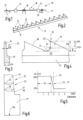
- FIG 1 a device 10 for producing a wire 11 is illustrated, as is needed to build an all-steel clothing of a clothing roller.
- the device 10 is used to produce this wire 11 from a profile wire 12, which is moved in its longitudinal direction L through the stations of the device 10.
- the device 10 includes, among other things, a punching station 13, which serves to make recesses 14 on the profile wire 12 ( Figure 2 ) and thus teeth 15 to form.
- a punching station 13 which serves to make recesses 14 on the profile wire 12 ( Figure 2 ) and thus teeth 15 to form.
- One or more straightening stations or other stations can be provided in front of the punching station 13.
- a grinding station or the like can be arranged after the punching station. Further stations arranged before or after the punching station 13, for example for straightening the profile wire 12 or the wire 11, can be provided if necessary, but are not shown.
- the punching station 13 is followed by a heating station, for example in the form of a first inductor 16, which serves to inductively heat the wire 11.
- the first inductor 16 generates a field that also detects at least the foot section 17 of the wire 11, but possibly also its teeth 15.
- the first inductor 16 operates with the first frequency f1 between 100 kHz and 5 MHz, preferably between 500 kHz and 2 MHz, in the present exemplary embodiment with 1 MHz.
- the wire 11 is heated to a first temperature t1 of preferably more than 300 ° C, particularly in the area of its foot section 17.
- the temperature t1 is 700°C to 750°C.
- she is preferably set in such a way that no hardening of the foot area 17 occurs during subsequent quenching.
- a second inductor 18 which operates at a significantly higher frequency f2. This is at least 5, preferably at least 10 and most preferably at least 20 times as high as the first frequency f1.
- the second frequency f2 is 20 MHz to 30 MHz, preferably 27 MHz.
- the second inductor 18 is preferably designed so that it only detects the teeth 15 or a section of each tooth 15. No active cooling of the wire 11 is provided between the inductors 16 and 18. Rather, the wire 11 passes through the distance in less than 2, preferably less than 1 s.
- Figure 4 illustrates a tooth 15 with a tooth height H15, which extends perpendicular to the longitudinal direction from the tooth base 21 to the tooth tip 20.
- a section 19 of the tooth 15 is defined, which extends from the tooth tip 20 to approximately its middle or slightly further towards the tooth base 21.
- the section 19 has a height H19, which is preferably greater than 70%, better greater than 80% of the tooth height H15.
- the second inductor 18 detects at least the section 19 of each tooth 15 or even a slightly larger area, but not the base of the tooth.
- the second inductor 18 and, if desired, also the first inductor 16 can work in an inert gas atmosphere, for example nitrogen. This can be brought up to a quenching station 22.
- the foot section 17 has a temperature t1 that is below the austenitization temperature range tA, while the section 19 of each tooth 15 has a temperature t2 that is in the austenitization temperature range tA.
- the temperature gradient from the section 19 to the foot section 17 causes the wire 11 to harden evenly when entering the quenching station 22, particularly at the section 19, but the wire 11 otherwise remains unhardened.
- the foot section 17 has a thickness D17 to be measured transversely to the longitudinal direction and perpendicular to the side surface, which is greater than the thickness D15 to be measured on each tooth 15.
- the heat storage capacity of the foot D17 is greater than the heat storage capacity of each tooth 15.
- excessive heat flow from the tooth 15 to the foot section 17 before reaching the quenching station 22 is avoided by increasing the temperature of the foot section 17 to the first temperature t1.
- the wall section 23 extends away from the foot section 17, which is typically rectangular in cross section, and can have a triangular or, as shown, trapezoidal cross section.
- a temperature transition zone 24 is formed on the wire 11, in which the temperature drops from the wide high temperature t2 (for example 950 ° C) to the first low temperature t1 (for example 550 ° C), which is to be measured below the temperature transition zone 24 on the remaining section of the wall 23 and the foot section 17.
- the in Figure 5 illustrated hardness curve.
- a uniform high hardness of over 800 HV 0.5 is achieved.
- a transition zone 24 of the hardness transition has formed from the temperature transition zone 24, in which the hardness drops from over 800 HV 0.5 to approximately 200 HV 0.5 or below.
- This zone has a vertical extent H24, measured away from the foot section 17, of preferably only 20% of the tooth height H15.
- the temperature transition zone 24 forms a straight strip extending in the longitudinal direction L with a width that corresponds to the height H24.
- This stiffener can be arranged at a distance A from the tooth base 24. However, it is also possible and advantageous to reduce the distance A to zero, so that the zone 24 touches the tooth base 21 with its boundary on the foot section side. It is also possible to set the transition zone 24 even deeper, so that the tooth base 21 lies in the area of the hardness transition of the transition zone 24.
- Figure 6 illustrates the transition zone 24 in cross section.
- the transition zone 24 is delimited from the hardened or non-hardened area across the wall section along curved lines 27, 28.
- the lines 27, 28 follow arcs that are curved towards the base 17a.
- the center of curvature is preferably on the side of each line 27, 28 lying away from the foot section 17, again preferably within the cross section of the tooth 15.
- the boundaries of the transition zone 24 are visible in the cross section of the all-steel set.
- the thermal load (source or sink) of the foot section 17 can be adjusted in this way that the lines 25 and/or 26 run obliquely to the base surface 17a. It then applies to the lines 27 and/or 28 that they end at different heights on the two sides of the tooth 15.
- a wire 11 provided with teeth 15 successively passes through a first inductor 16 and a second inductor 18.
- the inductors 16, 18 operate at different frequencies f1, f2 and generate different temperatures t1, t2.
- the first inductor 16 heats in particular the foot sections 17 that are not to be hardened to a high temperature t1 below the austenitization temperature range tA.
- the second inductor 18 heats the teeth 15 to an even higher second temperature t2, which lies in the austenitizing temperature range tA. Quenching produces defined, hardened teeth of consistently high quality.
- the wire can pass through a third inductor 29.
- the frequency f3 can match the first frequency f1.
- the temperature t3 generated by the third inductor 29 is a tempering temperature of, for example, a few hundred degrees Celsius.
- the wire 11 can be passed through a deburring station before or after tempering.
- punching burrs that may have arisen when punching out the recesses 14 can be removed, for example, by brushing, which, for example, only acts on one flat side of the teeth 15.
- a wire 11 provided with teeth 15 successively passes through a first inductor 16 and a second inductor 18.
- the inductors 16, 18 operate at different frequencies and generate different temperatures.
- the first inductor 16 heats in particular the foot section 17 that is not to be hardened to a high temperature below the austenitization temperature range.
- the second inductor 18 heats the teeth 15 to an even higher second temperature within the austenitizing temperature range. Quenching produces defined, hardened teeth of consistently high quality.
Landscapes
- Chemical & Material Sciences (AREA)
- Engineering & Computer Science (AREA)
- Materials Engineering (AREA)
- Thermal Sciences (AREA)
- Crystallography & Structural Chemistry (AREA)
- Mechanical Engineering (AREA)
- Physics & Mathematics (AREA)
- Metallurgy (AREA)
- Organic Chemistry (AREA)
- Textile Engineering (AREA)
- Heat Treatment Of Articles (AREA)
- Preliminary Treatment Of Fibers (AREA)
- General Induction Heating (AREA)
Claims (15)
- Garniture de carde faite de bandes métalliques, destinée à des machines à carder et constituée d'un fil métallique (11) définissant une direction longitudinale (L) et comportant une partie de pied (17) et une partie de paroi (23), dotée de dents (15) ayant une hauteur de dent (H15), qui présente au moins une partie trempée (19) et est orientée dans le sens opposé à la partie de pied (17),la partie de pied (17) présentant une épaisseur (D17) supérieure à celle de la partie de paroi (23),la partie de paroi (23) présentant une limite sous forme de zone de transition (24) qui est parallèle à la direction longitudinale (L) et suit une ligne droite et au niveau de laquelle commence la dureté accrue,
caractérisée en ce quela zone de transition (24) est délimitée par rapport à la partie trempée (19) et la zone non trempée, le long de lignes courbes (27, 28), transversalement à la partie de paroi (23). - Garniture de carde faite de bandes métalliques selon la revendication 1, caractérisée en ce que la hauteur (H24) de la zone de transition (24) correspond au maximum à 20 % de la hauteur de dent (H15).
- Garniture de carde faite de bandes métalliques selon la revendication 1 ou 2, caractérisée en ce que la zone de transition (24) est réalisée à l'intérieur des dents.
- Garniture de carde faite de bandes métalliques selon l'une des revendications précédentes, caractérisée en ce qu'un fond de dent (21) est réalisé entre les dents (15), la distance de la zone de transition (24) par rapport à la pointe de dent (20) correspondant de préférence à au moins 70 % de la hauteur de dent (H15).
- Garniture de carde faite de bandes métalliques selon l'une des revendications 1 à 3, caractérisée en ce que la partie de paroi (23) présente des dents (15) entre lesquelles est formé respectivement un fond de dent (21), et en ce que la zone de transition (24) touche le fond de dent (21) ou le contient ou s'étend au-dessous de celui-ci.
- Garniture de carde faite de bandes métalliques selon l'une des revendications précédentes, caractérisée en ce que la partie de paroi (23) est réalisée avec une section transversale trapézoïdale ou triangulaire qui s'étend en diminuant à partir de la partie de pied (17).
- Garniture de carde faite de bandes métalliques selon l'une des revendications précédentes, caractérisée en ce que chaque dent (15) présente une pointe de dent (20) et un dos de dent (30) rectiligne qui s'étend jusqu'à la pointe de dent (20).
- Garniture de carde faite de bandes métalliques selon l'une des revendications précédentes, caractérisée en ce qu'elle présente un fini métallique brillant et/ou est exempte de calamine et ne comporte pas de traces d'ébavurage ou de post-traitement chimiques, ni de traces de post-traitement mécanique sur les deux faces.
- Procédé de fabrication d'une garniture de carde faite de bandes métalliques pour machines à carder, le procédé comprenant les étapes suivantes :préparation d'un fil métallique (11) comportant une partie de pied (17) et une partie de paroi (23) qui s'étend à partir de la partie de pied (17) et présente une épaisseur (D15) plus faible que celle-ci,réalisation d'évidements (14) dans la partie de paroi (23) du fil métallique de matière brute (12), en vue de former des dents (15) entre lesquelles est réalisé chaque fois un fond de dent (21),chauffage au moins de la partie de pied (17) du fil métallique (11), en passage continu, pour la porter à une première température (t1), à l'aide d'au moins un premier inducteur (16) avec une première fréquence (f1) définie,chauffage par induction, au moins par portions, de la partie de paroi (23) du fil métallique (11) qui est préchauffé au moins dans la partie de pied (17), en passage continu, à l'aide d'au moins un deuxième inducteur (18) avec une deuxième fréquence (f2) définie, pour la porter à une deuxième température (t2), le deuxième inducteur (18) couvrant au moins la partie (19) de chaque dent (15) ou également une zone plus grande, mais pas le fond de dent (21),la deuxième température (t2) étant supérieure à la première température (t1),trempe de la partie de paroi (23) du fil métallique (11), au nombre d'au moins une, en passage continu, avec un fluide de refroidissement.
- Procédé selon la revendication 9, caractérisé en ce que la première température (t1) est inférieure à une plage de températures d'austénitisation (tA), et la deuxième température se situe dans la plage de températures d'austénitisation (tA).
- Procédé selon la revendication 9 ou 10, caractérisé en ce que la deuxième fréquence (f2) est supérieure à la première fréquence (f1).
- Procédé selon la revendication 11, caractérisé en ce que la première fréquence (f1) est au maximum de 5 MHz, de préférence au maximum de 3 MHz, et en ce que la deuxième fréquence est au moins de 10 MHz, de préférence au moins de 15 MHz.
- Procédé selon l'une des revendications 11 ou 12, caractérisé en ce que, après la trempe, on fait passer le fil métallique (11) dans un troisième inducteur (29) fonctionnant à une troisième fréquence (f3) qui est inférieure à la deuxième fréquence (f2), afin de chauffer le fil métallique à une troisième température qui est au moins inférieure à la deuxième température (t2) et de préférence inférieure à la première température (t1).
- Procédé selon l'une des revendications 11 à 13, caractérisé en ce qu'au moins le chauffage par induction avec la deuxième fréquence (f2), pour atteindre la deuxième température (t2), est effectué sous gaz protecteur.
- Procédé selon l'une des revendications 9 à 14, caractérisé en ce que le fil métallique (11) est brossé sur au moins une surface latérale.
Priority Applications (1)
| Application Number | Priority Date | Filing Date | Title |
|---|---|---|---|
| EP19195680.4A EP3597802B1 (fr) | 2014-05-09 | 2014-05-09 | Garniture de carde faite de bandes métalliques et son procédé de fabrication |
Applications Claiming Priority (2)
| Application Number | Priority Date | Filing Date | Title |
|---|---|---|---|
| EP14167767.4A EP2942425B1 (fr) | 2014-05-09 | 2014-05-09 | Garniture de carde faite de bandes métalliques |
| EP19195680.4A EP3597802B1 (fr) | 2014-05-09 | 2014-05-09 | Garniture de carde faite de bandes métalliques et son procédé de fabrication |
Related Parent Applications (2)
| Application Number | Title | Priority Date | Filing Date |
|---|---|---|---|
| EP14167767.4A Division-Into EP2942425B1 (fr) | 2014-05-09 | 2014-05-09 | Garniture de carde faite de bandes métalliques |
| EP14167767.4A Division EP2942425B1 (fr) | 2014-05-09 | 2014-05-09 | Garniture de carde faite de bandes métalliques |
Publications (3)
| Publication Number | Publication Date |
|---|---|
| EP3597802A1 EP3597802A1 (fr) | 2020-01-22 |
| EP3597802C0 EP3597802C0 (fr) | 2023-12-20 |
| EP3597802B1 true EP3597802B1 (fr) | 2023-12-20 |
Family
ID=50685790
Family Applications (2)
| Application Number | Title | Priority Date | Filing Date |
|---|---|---|---|
| EP14167767.4A Active EP2942425B1 (fr) | 2014-05-09 | 2014-05-09 | Garniture de carde faite de bandes métalliques |
| EP19195680.4A Active EP3597802B1 (fr) | 2014-05-09 | 2014-05-09 | Garniture de carde faite de bandes métalliques et son procédé de fabrication |
Family Applications Before (1)
| Application Number | Title | Priority Date | Filing Date |
|---|---|---|---|
| EP14167767.4A Active EP2942425B1 (fr) | 2014-05-09 | 2014-05-09 | Garniture de carde faite de bandes métalliques |
Country Status (8)
| Country | Link |
|---|---|
| US (1) | US11414792B2 (fr) |
| EP (2) | EP2942425B1 (fr) |
| JP (2) | JP6794263B2 (fr) |
| KR (1) | KR102455649B1 (fr) |
| CN (3) | CN112553421A (fr) |
| BR (1) | BR112016025607B1 (fr) |
| RU (1) | RU2682530C2 (fr) |
| WO (1) | WO2015169797A1 (fr) |
Families Citing this family (4)
| Publication number | Priority date | Publication date | Assignee | Title |
|---|---|---|---|---|
| EP2942425B1 (fr) * | 2014-05-09 | 2019-11-20 | Groz-Beckert KG | Garniture de carde faite de bandes métalliques |
| DE102021102373A1 (de) | 2021-02-02 | 2022-08-04 | Groz-Beckert Kommanditgesellschaft | Verfahren zum Laserhärten eines Garniturdrahtes |
| US20240102120A1 (en) * | 2021-02-02 | 2024-03-28 | Groz-Beckert Kg | Method for laser hardening of a card wire |
| CN120505495B (zh) * | 2025-07-22 | 2025-09-12 | 烟台瑞玛纺织机械有限公司 | 一种循环冷却式圆机针热处理设备 |
Citations (2)
| Publication number | Priority date | Publication date | Assignee | Title |
|---|---|---|---|---|
| DE10238065A1 (de) * | 2001-10-02 | 2003-04-17 | Holding Fuer Industriebeteilig | Auflösewalze für eine Spinnstation einer Rotorspinnmaschine |
| CN1594606A (zh) * | 2003-09-12 | 2005-03-16 | 中国科学院力学研究所 | 一种采用yag激光器淬火处理金属针布的系统和方法 |
Family Cites Families (29)
| Publication number | Priority date | Publication date | Assignee | Title |
|---|---|---|---|---|
| DE10542C (de) | J. ENGEL in Berlin, Hochstrafse 421 | Abnehmbarer Bratofen-Aufsatz für Kochherde | ||
| US2326674A (en) * | 1940-07-26 | 1943-08-10 | Simonds Saw And Steel Co | Induction hardening of saw teeth |
| DE2332685A1 (de) | 1973-06-27 | 1975-01-23 | Stromeyer Albrecht Dr | Verfahren und vorrichtung zur spangebenden verformung von draehten oder dergleichen werkstuecken |
| US4109127A (en) * | 1973-07-25 | 1978-08-22 | Frank Frungel | Apparatus and method for case hardening steel tools by application of heating pulses |
| DE2904841A1 (de) | 1979-02-09 | 1980-08-21 | Fritz Stahlecker | Saegezahndraht fuer aufloesewalzen von offenend-spinnaggregaten |
| JPS5641320A (en) | 1979-09-11 | 1981-04-18 | Kanai Hiroyuki | Continuous annealing method for metallic card cloth |
| JPH0615726B2 (ja) * | 1985-01-07 | 1994-03-02 | 金井 宏之 | 紡機用メタリツクワイヤおよびその製造方法 |
| US5096506A (en) | 1988-11-18 | 1992-03-17 | Hollingsworth John D | Method for making card clothing |
| US4964195A (en) * | 1988-11-18 | 1990-10-23 | Hollingsworth John D | Metallic card clothing |
| JP2909774B2 (ja) * | 1990-12-28 | 1999-06-23 | 金井 宏之 | 紡機用メタリックワイヤの熱処理方法 |
| JPH07118935A (ja) | 1993-10-29 | 1995-05-09 | Kanai Hiroyuki | 紡機用メタリックワイヤ |
| DE19940845C1 (de) | 1999-08-27 | 2000-12-21 | Graf & Co Ag | Verfahren und Vorrichtung zum Herstellen von Feindraht |
| DE10007567C2 (de) | 2000-02-18 | 2003-08-07 | Graf & Co Ag | Verfahren und Vorrichtung zum Herstellen eines Drahtes |
| DE10106673A1 (de) | 2001-02-14 | 2002-08-29 | Rieter Ingolstadt Spinnerei | Verfahren zur Herstellung einer Auflösewalze einer Offenend-Spinnvorrichtung sowie eine mit Hilfe eines solchen Verfahrens hergestellte Auflösewalze |
| JP2004244748A (ja) | 2003-02-13 | 2004-09-02 | Kanai Hiroaki | 梳綿機用メタリックワイヤ |
| MXPA06012176A (es) * | 2004-04-21 | 2007-01-17 | Inductoheat Inc | Tratamiento termico a frecuencias multiples de una pieza de trabajo a traves de calentamiento por induccion. |
| DE102005025627B3 (de) | 2005-06-03 | 2006-10-05 | Graf + Cie Ag | Verfahren und Vorrichtung zum Herstellen von Sägezahn- und Ganzstahlgarnituren sowie Sägezahndraht |
| DE102006030418B4 (de) | 2006-06-29 | 2021-06-10 | Trützschler GmbH & Co Kommanditgesellschaft | Sägezahndraht zur Herstellung einer Sägezahnganzstahlgarnitur für eine Walze oder ein Kardierelement einer Spinnereimaschine |
| US7735201B1 (en) * | 2008-08-06 | 2010-06-15 | Nv Bekaert Sa | Multiple wire card wiring, carding cylinder, and method of making such |
| JP6007172B2 (ja) * | 2010-05-04 | 2016-10-12 | グローツ−ベッカート コマンディトゲゼルシャフト | 針布用ワイヤー異形材 |
| US8789244B2 (en) * | 2010-08-09 | 2014-07-29 | Nv Bekaert Sa | Wire profile for card clothing |
| WO2013037711A1 (fr) * | 2011-09-15 | 2013-03-21 | Nv Bekaert Sa | Fil de carde ayant des dents à forme améliorée |
| KR101795122B1 (ko) | 2011-11-15 | 2017-11-07 | 그로츠-베케르트 카게 | 금속 카드 와이어 |
| EP2918710A1 (fr) * | 2014-03-12 | 2015-09-16 | Groz-Beckert KG | Garniture de carde et procédé de fabrication d'un non-tissé de fibres discontinues |
| EP2942425B1 (fr) | 2014-05-09 | 2019-11-20 | Groz-Beckert KG | Garniture de carde faite de bandes métalliques |
| EP2944712B1 (fr) * | 2014-05-16 | 2018-09-05 | Groz-Beckert KG | Câble métallique pour garniture de carde |
| EP3191613B1 (fr) * | 2014-09-12 | 2019-01-23 | Aleris Aluminum Duffel BVBA | Procédé de recuit d'un matériau de feuille d'alliage d'aluminium |
| CH711166A1 (de) * | 2015-06-05 | 2016-12-15 | Graf + Cie Ag | Ganzstahlgarnitur. |
| CH713140A1 (de) * | 2016-11-16 | 2018-05-31 | Graf Cie Ag | Garniturdraht. |
-
2014
- 2014-05-09 EP EP14167767.4A patent/EP2942425B1/fr active Active
- 2014-05-09 EP EP19195680.4A patent/EP3597802B1/fr active Active
-
2015
- 2015-05-05 KR KR1020167031055A patent/KR102455649B1/ko active Active
- 2015-05-05 CN CN202011267008.6A patent/CN112553421A/zh active Pending
- 2015-05-05 BR BR112016025607-7A patent/BR112016025607B1/pt not_active IP Right Cessation
- 2015-05-05 CN CN201580024128.4A patent/CN106661646B/zh active Active
- 2015-05-05 JP JP2016567226A patent/JP6794263B2/ja active Active
- 2015-05-05 RU RU2016141256A patent/RU2682530C2/ru active
- 2015-05-05 WO PCT/EP2015/059839 patent/WO2015169797A1/fr not_active Ceased
- 2015-05-05 CN CN202111013753.2A patent/CN113699329A/zh active Pending
- 2015-05-05 US US15/309,745 patent/US11414792B2/en active Active
-
2020
- 2020-11-11 JP JP2020188156A patent/JP7537069B2/ja active Active
Patent Citations (2)
| Publication number | Priority date | Publication date | Assignee | Title |
|---|---|---|---|---|
| DE10238065A1 (de) * | 2001-10-02 | 2003-04-17 | Holding Fuer Industriebeteilig | Auflösewalze für eine Spinnstation einer Rotorspinnmaschine |
| CN1594606A (zh) * | 2003-09-12 | 2005-03-16 | 中国科学院力学研究所 | 一种采用yag激光器淬火处理金属针布的系统和方法 |
Also Published As
| Publication number | Publication date |
|---|---|
| WO2015169797A1 (fr) | 2015-11-12 |
| CN106661646B (zh) | 2021-08-17 |
| BR112016025607A2 (fr) | 2017-08-15 |
| JP2017519104A (ja) | 2017-07-13 |
| JP6794263B2 (ja) | 2020-12-02 |
| US11414792B2 (en) | 2022-08-16 |
| EP2942425B1 (fr) | 2019-11-20 |
| RU2682530C2 (ru) | 2019-03-19 |
| EP3597802C0 (fr) | 2023-12-20 |
| US20170145600A1 (en) | 2017-05-25 |
| JP7537069B2 (ja) | 2024-08-21 |
| CN112553421A (zh) | 2021-03-26 |
| CN106661646A (zh) | 2017-05-10 |
| BR112016025607B1 (pt) | 2022-03-15 |
| RU2016141256A3 (fr) | 2018-08-31 |
| KR20160149212A (ko) | 2016-12-27 |
| RU2016141256A (ru) | 2018-06-09 |
| JP2021038462A (ja) | 2021-03-11 |
| EP3597802A1 (fr) | 2020-01-22 |
| KR102455649B1 (ko) | 2022-10-19 |
| EP2942425A1 (fr) | 2015-11-11 |
| CN113699329A (zh) | 2021-11-26 |
Similar Documents
| Publication | Publication Date | Title |
|---|---|---|
| DE112009000750B4 (de) | Stahlgegenstand, Verfahren zur Herstellung des Stahlgegenstands und Vorrichtung zur Herstellung eines Stahlgegenstands | |
| EP2028281B1 (fr) | Traitement thermique d'une bande laminée flexible | |
| EP2014777B1 (fr) | Procédé et dispositif pour le traitement thermique d'une tôle métallique | |
| DE102014110415B4 (de) | Verfahren zum Aufheizen von Stahlblechen und Vorrichtung zur Durchführung des Verfahrens | |
| EP3597802B1 (fr) | Garniture de carde faite de bandes métalliques et son procédé de fabrication | |
| EP2907881A2 (fr) | Ligne moulée à chaud et procédé de fabrication de produits de tôle moulés à chaud | |
| EP0384964A1 (fr) | Procédé et dispositif pour le durcissement par induction des surfaces ondulées d'une pièce | |
| EP2883967B1 (fr) | Procédé et dispositif de post-traitement d'un élément de formage métallique durci au moyen du chauffage par résistance électrique | |
| DE102014000129B3 (de) | Verfahren und Vorrichtung zum Schränken von Bandsägeblättern | |
| DE102014106574B4 (de) | Ganzstahlgarnitur | |
| WO2016177733A1 (fr) | Procédé et dispositif de trempe de proche en proche par induction avec préchauffage commandable et avec un inducteur conçu pour le préchauffage et la trempe | |
| DE102011007590B4 (de) | Verfahren und Vorrichtung zum Gleitziehbiegen | |
| DE102019202000A1 (de) | Vorrichtung und Verfahren zum induktiven Vorschubhärten von Wälzlagerlaufbahnen | |
| EP2371983A1 (fr) | Procédé d'amélioration d'un composant en fonte ainsi que composant en fonte fabriqué selon le procédé | |
| EP0442864B1 (fr) | Méthode et arrangement pour le laminage de barres et fils | |
| DE102006015669B3 (de) | Verfahren und Vorrichtung zum Umwandeln metallischen Gefüges | |
| AT513628B1 (de) | Verfahren und Vorrichtung zum Wärmebehandeln von Langprodukten | |
| EP0340747A2 (fr) | Procédé et dispositif pour améliorer la qualité de l'enduction du matériau métallique en forme de barres | |
| DE102015122390B4 (de) | Verfahren zur konduktiven Erwärmung eines flächig ausgebildeten metallischen Bauteils | |
| AT514367B1 (de) | Hohle Zahnstange und Verfahren zu deren Herstellung | |
| EP4261295A1 (fr) | Procédé de fabrication d'une lame | |
| DE102023105277A1 (de) | Fertigungsanlage zur Wärmebehandlung von warm- und kaltgeformten Federelementen, sowie ein Verfahren zur Wärmebehandlung von kaltgeformten Federelementen | |
| WO2013030017A1 (fr) | Dispositif permettant de durcir une surface pourvue d'éléments de type nervure ou dent | |
| DE3234299C2 (de) | Verfahren zum Oberflächenhärten von Werkstücken und Vorrichtung zum Durchführen des Verfahrens | |
| EP3985133A2 (fr) | Procédé de fabrication d'une platine d'acier, ainsi que station de thermorégulation |
Legal Events
| Date | Code | Title | Description |
|---|---|---|---|
| PUAI | Public reference made under article 153(3) epc to a published international application that has entered the european phase |
Free format text: ORIGINAL CODE: 0009012 |
|
| STAA | Information on the status of an ep patent application or granted ep patent |
Free format text: STATUS: REQUEST FOR EXAMINATION WAS MADE |
|
| 17P | Request for examination filed |
Effective date: 20190905 |
|
| AC | Divisional application: reference to earlier application |
Ref document number: 2942425 Country of ref document: EP Kind code of ref document: P |
|
| AK | Designated contracting states |
Kind code of ref document: A1 Designated state(s): AL AT BE BG CH CY CZ DE DK EE ES FI FR GB GR HR HU IE IS IT LI LT LU LV MC MK MT NL NO PL PT RO RS SE SI SK SM TR |
|
| STAA | Information on the status of an ep patent application or granted ep patent |
Free format text: STATUS: EXAMINATION IS IN PROGRESS |
|
| 17Q | First examination report despatched |
Effective date: 20220603 |
|
| RIC1 | Information provided on ipc code assigned before grant |
Ipc: C21D 9/24 20060101ALN20230420BHEP Ipc: C21D 1/42 20060101ALI20230420BHEP Ipc: C21D 1/10 20060101ALI20230420BHEP Ipc: C21D 9/26 20060101ALI20230420BHEP Ipc: D01G 15/88 20060101AFI20230420BHEP |
|
| GRAP | Despatch of communication of intention to grant a patent |
Free format text: ORIGINAL CODE: EPIDOSNIGR1 |
|
| STAA | Information on the status of an ep patent application or granted ep patent |
Free format text: STATUS: GRANT OF PATENT IS INTENDED |
|
| RIC1 | Information provided on ipc code assigned before grant |
Ipc: C21D 9/24 20060101ALN20230627BHEP Ipc: C21D 1/42 20060101ALI20230627BHEP Ipc: C21D 1/10 20060101ALI20230627BHEP Ipc: C21D 9/26 20060101ALI20230627BHEP Ipc: D01G 15/88 20060101AFI20230627BHEP |
|
| INTG | Intention to grant announced |
Effective date: 20230713 |
|
| GRAS | Grant fee paid |
Free format text: ORIGINAL CODE: EPIDOSNIGR3 |
|
| GRAA | (expected) grant |
Free format text: ORIGINAL CODE: 0009210 |
|
| STAA | Information on the status of an ep patent application or granted ep patent |
Free format text: STATUS: THE PATENT HAS BEEN GRANTED |
|
| AC | Divisional application: reference to earlier application |
Ref document number: 2942425 Country of ref document: EP Kind code of ref document: P |
|
| AK | Designated contracting states |
Kind code of ref document: B1 Designated state(s): AL AT BE BG CH CY CZ DE DK EE ES FI FR GB GR HR HU IE IS IT LI LT LU LV MC MK MT NL NO PL PT RO RS SE SI SK SM TR |
|
| REG | Reference to a national code |
Ref country code: GB Ref legal event code: FG4D Free format text: NOT ENGLISH |
|
| REG | Reference to a national code |
Ref country code: CH Ref legal event code: EP |
|
| REG | Reference to a national code |
Ref country code: DE Ref legal event code: R096 Ref document number: 502014016745 Country of ref document: DE |
|
| REG | Reference to a national code |
Ref country code: IE Ref legal event code: FG4D Free format text: LANGUAGE OF EP DOCUMENT: GERMAN |
|
| U01 | Request for unitary effect filed |
Effective date: 20231222 |
|
| U07 | Unitary effect registered |
Designated state(s): AT BE BG DE DK EE FI FR IT LT LU LV MT NL PT SE SI Effective date: 20240109 |
|
| PG25 | Lapsed in a contracting state [announced via postgrant information from national office to epo] |
Ref country code: GR Free format text: LAPSE BECAUSE OF FAILURE TO SUBMIT A TRANSLATION OF THE DESCRIPTION OR TO PAY THE FEE WITHIN THE PRESCRIBED TIME-LIMIT Effective date: 20240321 |
|
| PG25 | Lapsed in a contracting state [announced via postgrant information from national office to epo] |
Ref country code: ES Free format text: LAPSE BECAUSE OF FAILURE TO SUBMIT A TRANSLATION OF THE DESCRIPTION OR TO PAY THE FEE WITHIN THE PRESCRIBED TIME-LIMIT Effective date: 20231220 |
|
| PG25 | Lapsed in a contracting state [announced via postgrant information from national office to epo] |
Ref country code: GR Free format text: LAPSE BECAUSE OF FAILURE TO SUBMIT A TRANSLATION OF THE DESCRIPTION OR TO PAY THE FEE WITHIN THE PRESCRIBED TIME-LIMIT Effective date: 20240321 Ref country code: ES Free format text: LAPSE BECAUSE OF FAILURE TO SUBMIT A TRANSLATION OF THE DESCRIPTION OR TO PAY THE FEE WITHIN THE PRESCRIBED TIME-LIMIT Effective date: 20231220 |
|
| PG25 | Lapsed in a contracting state [announced via postgrant information from national office to epo] |
Ref country code: RS Free format text: LAPSE BECAUSE OF FAILURE TO SUBMIT A TRANSLATION OF THE DESCRIPTION OR TO PAY THE FEE WITHIN THE PRESCRIBED TIME-LIMIT Effective date: 20231220 Ref country code: NO Free format text: LAPSE BECAUSE OF FAILURE TO SUBMIT A TRANSLATION OF THE DESCRIPTION OR TO PAY THE FEE WITHIN THE PRESCRIBED TIME-LIMIT Effective date: 20240320 Ref country code: HR Free format text: LAPSE BECAUSE OF FAILURE TO SUBMIT A TRANSLATION OF THE DESCRIPTION OR TO PAY THE FEE WITHIN THE PRESCRIBED TIME-LIMIT Effective date: 20231220 |
|
| PG25 | Lapsed in a contracting state [announced via postgrant information from national office to epo] |
Ref country code: IS Free format text: LAPSE BECAUSE OF FAILURE TO SUBMIT A TRANSLATION OF THE DESCRIPTION OR TO PAY THE FEE WITHIN THE PRESCRIBED TIME-LIMIT Effective date: 20240420 |
|
| U20 | Renewal fee for the european patent with unitary effect paid |
Year of fee payment: 11 Effective date: 20240531 |
|
| PG25 | Lapsed in a contracting state [announced via postgrant information from national office to epo] |
Ref country code: CZ Free format text: LAPSE BECAUSE OF FAILURE TO SUBMIT A TRANSLATION OF THE DESCRIPTION OR TO PAY THE FEE WITHIN THE PRESCRIBED TIME-LIMIT Effective date: 20231220 |
|
| PG25 | Lapsed in a contracting state [announced via postgrant information from national office to epo] |
Ref country code: SK Free format text: LAPSE BECAUSE OF FAILURE TO SUBMIT A TRANSLATION OF THE DESCRIPTION OR TO PAY THE FEE WITHIN THE PRESCRIBED TIME-LIMIT Effective date: 20231220 |
|
| PG25 | Lapsed in a contracting state [announced via postgrant information from national office to epo] |
Ref country code: SM Free format text: LAPSE BECAUSE OF FAILURE TO SUBMIT A TRANSLATION OF THE DESCRIPTION OR TO PAY THE FEE WITHIN THE PRESCRIBED TIME-LIMIT Effective date: 20231220 Ref country code: SK Free format text: LAPSE BECAUSE OF FAILURE TO SUBMIT A TRANSLATION OF THE DESCRIPTION OR TO PAY THE FEE WITHIN THE PRESCRIBED TIME-LIMIT Effective date: 20231220 Ref country code: RO Free format text: LAPSE BECAUSE OF FAILURE TO SUBMIT A TRANSLATION OF THE DESCRIPTION OR TO PAY THE FEE WITHIN THE PRESCRIBED TIME-LIMIT Effective date: 20231220 Ref country code: IS Free format text: LAPSE BECAUSE OF FAILURE TO SUBMIT A TRANSLATION OF THE DESCRIPTION OR TO PAY THE FEE WITHIN THE PRESCRIBED TIME-LIMIT Effective date: 20240420 Ref country code: CZ Free format text: LAPSE BECAUSE OF FAILURE TO SUBMIT A TRANSLATION OF THE DESCRIPTION OR TO PAY THE FEE WITHIN THE PRESCRIBED TIME-LIMIT Effective date: 20231220 |
|
| PG25 | Lapsed in a contracting state [announced via postgrant information from national office to epo] |
Ref country code: PL Free format text: LAPSE BECAUSE OF FAILURE TO SUBMIT A TRANSLATION OF THE DESCRIPTION OR TO PAY THE FEE WITHIN THE PRESCRIBED TIME-LIMIT Effective date: 20231220 |
|
| PG25 | Lapsed in a contracting state [announced via postgrant information from national office to epo] |
Ref country code: PL Free format text: LAPSE BECAUSE OF FAILURE TO SUBMIT A TRANSLATION OF THE DESCRIPTION OR TO PAY THE FEE WITHIN THE PRESCRIBED TIME-LIMIT Effective date: 20231220 |
|
| PGFP | Annual fee paid to national office [announced via postgrant information from national office to epo] |
Ref country code: TR Payment date: 20240422 Year of fee payment: 11 |
|
| REG | Reference to a national code |
Ref country code: DE Ref legal event code: R097 Ref document number: 502014016745 Country of ref document: DE |
|
| PLBE | No opposition filed within time limit |
Free format text: ORIGINAL CODE: 0009261 |
|
| STAA | Information on the status of an ep patent application or granted ep patent |
Free format text: STATUS: NO OPPOSITION FILED WITHIN TIME LIMIT |
|
| 26N | No opposition filed |
Effective date: 20240923 |
|
| PG25 | Lapsed in a contracting state [announced via postgrant information from national office to epo] |
Ref country code: MC Free format text: LAPSE BECAUSE OF FAILURE TO SUBMIT A TRANSLATION OF THE DESCRIPTION OR TO PAY THE FEE WITHIN THE PRESCRIBED TIME-LIMIT Effective date: 20231220 |
|
| PG25 | Lapsed in a contracting state [announced via postgrant information from national office to epo] |
Ref country code: MC Free format text: LAPSE BECAUSE OF FAILURE TO SUBMIT A TRANSLATION OF THE DESCRIPTION OR TO PAY THE FEE WITHIN THE PRESCRIBED TIME-LIMIT Effective date: 20231220 |
|
| PG25 | Lapsed in a contracting state [announced via postgrant information from national office to epo] |
Ref country code: IE Free format text: LAPSE BECAUSE OF NON-PAYMENT OF DUE FEES Effective date: 20240509 |
|
| PGFP | Annual fee paid to national office [announced via postgrant information from national office to epo] |
Ref country code: GB Payment date: 20250320 Year of fee payment: 12 |
|
| U1N | Appointed representative for the unitary patent procedure changed after the registration of the unitary effect |
Representative=s name: RUEGER ABEL PATENTANWAELTE PARTGMBB; DE |
|
| PGFP | Annual fee paid to national office [announced via postgrant information from national office to epo] |
Ref country code: CH Payment date: 20250601 Year of fee payment: 12 |
|
| PG25 | Lapsed in a contracting state [announced via postgrant information from national office to epo] |
Ref country code: CY Free format text: LAPSE BECAUSE OF FAILURE TO SUBMIT A TRANSLATION OF THE DESCRIPTION OR TO PAY THE FEE WITHIN THE PRESCRIBED TIME-LIMIT; INVALID AB INITIO Effective date: 20140509 |
|
| PG25 | Lapsed in a contracting state [announced via postgrant information from national office to epo] |
Ref country code: HU Free format text: LAPSE BECAUSE OF FAILURE TO SUBMIT A TRANSLATION OF THE DESCRIPTION OR TO PAY THE FEE WITHIN THE PRESCRIBED TIME-LIMIT; INVALID AB INITIO Effective date: 20140509 |
|
| U90 | Renewal fees not paid: noting of loss of rights |
Free format text: RENEWAL FEE NOT PAID FOR YEAR 12 Effective date: 20251218 |
|
| U93 | Unitary patent lapsed |
Free format text: RENEWAL FEE NOT PAID Effective date: 20250531 |