EP3597878A1 - Chauffage de citerne - Google Patents
Chauffage de citerne Download PDFInfo
- Publication number
- EP3597878A1 EP3597878A1 EP19186526.0A EP19186526A EP3597878A1 EP 3597878 A1 EP3597878 A1 EP 3597878A1 EP 19186526 A EP19186526 A EP 19186526A EP 3597878 A1 EP3597878 A1 EP 3597878A1
- Authority
- EP
- European Patent Office
- Prior art keywords
- housing
- ptc
- tank
- heater according
- heat
- Prior art date
- Legal status (The legal status is an assumption and is not a legal conclusion. Google has not performed a legal analysis and makes no representation as to the accuracy of the status listed.)
- Granted
Links
Images




Classifications
-
- H—ELECTRICITY
- H05—ELECTRIC TECHNIQUES NOT OTHERWISE PROVIDED FOR
- H05B—ELECTRIC HEATING; ELECTRIC LIGHT SOURCES NOT OTHERWISE PROVIDED FOR; CIRCUIT ARRANGEMENTS FOR ELECTRIC LIGHT SOURCES, IN GENERAL
- H05B3/00—Ohmic-resistance heating
- H05B3/02—Details
- H05B3/06—Heater elements structurally combined with coupling elements or holders
-
- H—ELECTRICITY
- H05—ELECTRIC TECHNIQUES NOT OTHERWISE PROVIDED FOR
- H05B—ELECTRIC HEATING; ELECTRIC LIGHT SOURCES NOT OTHERWISE PROVIDED FOR; CIRCUIT ARRANGEMENTS FOR ELECTRIC LIGHT SOURCES, IN GENERAL
- H05B3/00—Ohmic-resistance heating
- H05B3/78—Heating arrangements specially adapted for immersion heating
- H05B3/82—Fixedly-mounted immersion heaters
-
- F—MECHANICAL ENGINEERING; LIGHTING; HEATING; WEAPONS; BLASTING
- F01—MACHINES OR ENGINES IN GENERAL; ENGINE PLANTS IN GENERAL; STEAM ENGINES
- F01N—GAS-FLOW SILENCERS OR EXHAUST APPARATUS FOR MACHINES OR ENGINES IN GENERAL; GAS-FLOW SILENCERS OR EXHAUST APPARATUS FOR INTERNAL-COMBUSTION ENGINES
- F01N2530/00—Selection of materials for tubes, chambers or housings
- F01N2530/18—Plastics material, e.g. polyester resin
-
- F—MECHANICAL ENGINEERING; LIGHTING; HEATING; WEAPONS; BLASTING
- F01—MACHINES OR ENGINES IN GENERAL; ENGINE PLANTS IN GENERAL; STEAM ENGINES
- F01N—GAS-FLOW SILENCERS OR EXHAUST APPARATUS FOR MACHINES OR ENGINES IN GENERAL; GAS-FLOW SILENCERS OR EXHAUST APPARATUS FOR INTERNAL-COMBUSTION ENGINES
- F01N2610/00—Adding substances to exhaust gases
- F01N2610/02—Adding substances to exhaust gases the substance being ammonia or urea
-
- F—MECHANICAL ENGINEERING; LIGHTING; HEATING; WEAPONS; BLASTING
- F01—MACHINES OR ENGINES IN GENERAL; ENGINE PLANTS IN GENERAL; STEAM ENGINES
- F01N—GAS-FLOW SILENCERS OR EXHAUST APPARATUS FOR MACHINES OR ENGINES IN GENERAL; GAS-FLOW SILENCERS OR EXHAUST APPARATUS FOR INTERNAL-COMBUSTION ENGINES
- F01N2610/00—Adding substances to exhaust gases
- F01N2610/10—Adding substances to exhaust gases the substance being heated, e.g. by heating tank or supply line of the added substance
-
- F—MECHANICAL ENGINEERING; LIGHTING; HEATING; WEAPONS; BLASTING
- F01—MACHINES OR ENGINES IN GENERAL; ENGINE PLANTS IN GENERAL; STEAM ENGINES
- F01N—GAS-FLOW SILENCERS OR EXHAUST APPARATUS FOR MACHINES OR ENGINES IN GENERAL; GAS-FLOW SILENCERS OR EXHAUST APPARATUS FOR INTERNAL-COMBUSTION ENGINES
- F01N2610/00—Adding substances to exhaust gases
- F01N2610/14—Arrangements for the supply of substances, e.g. conduits
- F01N2610/1406—Storage means for substances, e.g. tanks or reservoirs
-
- F—MECHANICAL ENGINEERING; LIGHTING; HEATING; WEAPONS; BLASTING
- F01—MACHINES OR ENGINES IN GENERAL; ENGINE PLANTS IN GENERAL; STEAM ENGINES
- F01N—GAS-FLOW SILENCERS OR EXHAUST APPARATUS FOR MACHINES OR ENGINES IN GENERAL; GAS-FLOW SILENCERS OR EXHAUST APPARATUS FOR INTERNAL-COMBUSTION ENGINES
- F01N3/00—Exhaust or silencing apparatus having means for purifying, rendering innocuous, or otherwise treating exhaust
- F01N3/08—Exhaust or silencing apparatus having means for purifying, rendering innocuous, or otherwise treating exhaust for rendering innocuous
- F01N3/10—Exhaust or silencing apparatus having means for purifying, rendering innocuous, or otherwise treating exhaust for rendering innocuous by thermal or catalytic conversion of noxious components of exhaust
- F01N3/18—Exhaust or silencing apparatus having means for purifying, rendering innocuous, or otherwise treating exhaust for rendering innocuous by thermal or catalytic conversion of noxious components of exhaust characterised by methods of operation; Control
- F01N3/20—Exhaust or silencing apparatus having means for purifying, rendering innocuous, or otherwise treating exhaust for rendering innocuous by thermal or catalytic conversion of noxious components of exhaust characterised by methods of operation; Control specially adapted for catalytic conversion
- F01N3/206—Adding periodically or continuously substances to exhaust gases for promoting purification, e.g. catalytic material in liquid form, NOx reducing agents
- F01N3/2066—Selective catalytic reduction [SCR]
-
- H—ELECTRICITY
- H05—ELECTRIC TECHNIQUES NOT OTHERWISE PROVIDED FOR
- H05B—ELECTRIC HEATING; ELECTRIC LIGHT SOURCES NOT OTHERWISE PROVIDED FOR; CIRCUIT ARRANGEMENTS FOR ELECTRIC LIGHT SOURCES, IN GENERAL
- H05B2203/00—Aspects relating to Ohmic resistive heating covered by group H05B3/00
- H05B2203/016—Heaters using particular connecting means
-
- H—ELECTRICITY
- H05—ELECTRIC TECHNIQUES NOT OTHERWISE PROVIDED FOR
- H05B—ELECTRIC HEATING; ELECTRIC LIGHT SOURCES NOT OTHERWISE PROVIDED FOR; CIRCUIT ARRANGEMENTS FOR ELECTRIC LIGHT SOURCES, IN GENERAL
- H05B2203/00—Aspects relating to Ohmic resistive heating covered by group H05B3/00
- H05B2203/02—Heaters using heating elements having a positive temperature coefficient
-
- H—ELECTRICITY
- H05—ELECTRIC TECHNIQUES NOT OTHERWISE PROVIDED FOR
- H05B—ELECTRIC HEATING; ELECTRIC LIGHT SOURCES NOT OTHERWISE PROVIDED FOR; CIRCUIT ARRANGEMENTS FOR ELECTRIC LIGHT SOURCES, IN GENERAL
- H05B2203/00—Aspects relating to Ohmic resistive heating covered by group H05B3/00
- H05B2203/021—Heaters specially adapted for heating liquids
-
- Y—GENERAL TAGGING OF NEW TECHNOLOGICAL DEVELOPMENTS; GENERAL TAGGING OF CROSS-SECTIONAL TECHNOLOGIES SPANNING OVER SEVERAL SECTIONS OF THE IPC; TECHNICAL SUBJECTS COVERED BY FORMER USPC CROSS-REFERENCE ART COLLECTIONS [XRACs] AND DIGESTS
- Y02—TECHNOLOGIES OR APPLICATIONS FOR MITIGATION OR ADAPTATION AGAINST CLIMATE CHANGE
- Y02A—TECHNOLOGIES FOR ADAPTATION TO CLIMATE CHANGE
- Y02A50/00—TECHNOLOGIES FOR ADAPTATION TO CLIMATE CHANGE in human health protection, e.g. against extreme weather
- Y02A50/20—Air quality improvement or preservation, e.g. vehicle emission control or emission reduction by using catalytic converters
Definitions
- the invention relates to a tank heater for a motor vehicle, as shown in the EP 2 650 497 A1 is known.
- the tank heater can be intended, for example, for a tank that contains water, urea solution or another corrosive liquid.
- Tank heaters are exposed to the liquids contained in the tank during operation. Especially in the case of corrosive liquids, such as urea solution, electrical components of the tank heater must therefore be protected against contact with the liquid. As a rule, this is achieved with a plastic housing in which a metal heat-conducting body is enclosed in a liquid-tight manner together with one or more PTC heaters.
- the plastic housing can be produced by extrusion coating or can be formed from a lower housing part, into which the heat-conducting body and the PTC heater or heaters are inserted, and a housing cover welded to the lower part.
- the object of the present invention is to show a way in which a tank heater can be created which can be installed in a tank with little effort, is effectively protected against damage by liquid, can be connected to a power source with little effort and enables economical production ,
- the electrical connections of the PTC heater surrounded by the plastic housing are led through the housing cover.
- the housing cover has an opening into which a connector housing is fitted.
- the opening is thus sealed by the connector housing and the electrical connections are passed through the opening of the housing cover.
- the opening is preferably sealed by a sealing ring which surrounds the connector housing in the opening.
- the opening can also be sealed, for example, by an adhesive connection between the housing cover and the connector housing. Electrical components of the tank heating can be protected easily and reliably against contact with liquid. It is particularly advantageous that the tank heater can be easily equipped with different connectors depending on the customer's requirements and can thus be adapted to different standards.
- the connector housing can thus be designed in different variants to match the interfaces required by different automobile manufacturers.
- the sealing ring can sit in a groove of the cover or - which is preferred - in a groove of the connector housing, since this facilitates pre-assembly.
- the sealing ring can be an O-ring, for example.
- two or more O-rings can also be used side by side to seal the opening.
- plastics can advantageously be used for the plastic housing and the connector housing, for example polyethylene for the plastic housing and a polyamide for the connector housing.
- a PTC heater of the tank heater contains at least one ceramic PTC resistor, for example based on barium titanate, and at least one contact plate, which bears on the PTC resistor and makes electrical contact with it.
- the PTC resistor can be grounded via the heat sink or a second contact plate on the PTC heater.
- the housing cover has an annular wall which surrounds its opening.
- the tank heater can be installed particularly easily in a tank, namely by inserting the tank heater from the inside into an opening that matches the ring wall and then welding the ring wall to the tank.
- the ring wall can be circular or have another shape, such as an elliptical or even an angular shape.
- the mechanical connection by welding the ring wall to the tank can be inadequate. It can therefore be advantageous to provide fastening lugs on the housing cover for an additional connection to the tank wall. If the heat-conducting body has cooling fins and the lower housing part has a matching shape, such attachment approaches can be arranged, for example, between the cooling fins or covering an intermediate space between the cooling fins.
- a further advantageous development of the invention provides that the PTC heater or heaters are arranged in chambers of the heat-conducting body, which are designed as channels that pass through the heat-conducting body.
- the heat-conducting bodies preferably have ribs and a base connecting them, in which the chambers are designed as channels.
- Such heat conducting bodies can be produced inexpensively as extruded profiles.
- the PTC heater is preferably pressed into the chambers and the heat coupling of the PTC heater to the heat conducting body is improved.
- One chamber has side walls running across a contact plate of the PTC heater, as well as a bottom wall and a top wall. The side walls preferably have a thickness that is greater than the thickness of the bottom wall and greater than the thickness of the top wall.
- the side walls facing an adjacent chamber preferably extend over their entire height from one chamber to the adjacent chamber.
- the wall thickness of opposite walls of the heat-conducting body is not the same.
- the pressure required for pressing can be significantly reduced, since with a thinner wall, less plastic deformation of the heat-conducting body is necessary until it lies flat on the PTC heater with good thermal contact.
- the heat-conducting body also has a groove on both sides of the chambers on the ceiling wall. The grooves limit the pressing pressure.
- the PTC heater with a separate component, for example a spring clip or sheet, against an outer surface or an inner surface of a heat-conducting body and thus thermally couple it to the heat-conducting body.
- a separate component for example a spring clip or sheet
- plug connector forms an assembly together with the heat-conducting body and the PTC heater or the PTC heaters, which is inserted into the lower part of the plastic housing.
- the electrical components of the tank heating can thus advantageously be preassembled.
- Plug contacts of the connector can advantageously be formed by contact elements of the PTC heater or one of the PTC heaters, for example as sections of contact plates, between which a PTC resistor is arranged.
- the PTC heaters can have a mounting frame in which at least one PTC resistor and at least one contact plate which is in contact with the PTC resistor are arranged.
- the mounting frame can, for example, form a carrier or a compartment for a PTC resistor and a contact plate, so that the PTC heater can be connected to the heat-conducting body as an easily manageable unit, for example by inserting the PTC heater into a channel of the heat-conducting body.
- the connector housing is preferably formed in one piece with the or one of the mounting frames.
- a tank heater according to the invention preferably contains a plurality of PTC heaters which are electrically connected to one another by means of a contact rail which can be arranged between the heat-conducting body and the housing cover, but is preferably arranged between the heat-conducting body and a bottom of the lower part of the plastic housing.
- a contact rail which can be arranged between the heat-conducting body and the housing cover, but is preferably arranged between the heat-conducting body and a bottom of the lower part of the plastic housing.
- the contact rail can be held by a holder made of plastic, for example injected into the lower part of the plastic housing or clipped onto the holder. If the heat-conducting body is not used as a ground contact, the holder can also carry two such contact rails.
- the PTC heaters be modularly connected in the simplest way, but also several, preferably identical, heat-conducting elements.
- two contact rails connecting the heat-conducting elements ensure the problem-free electrical connection of the respective PTC heater arranged therein.
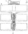
- the tank heater has a plastic housing which has a lower part 1 and a housing cover 2 welded to the lower part 1.
- the housing cover 2 has an opening into which a connector housing 3 is fitted. The opening of the housing cover 2 is therefore closed by the connector housing 3.
- a sealing ring surrounding the connector housing 3 is arranged in the opening, so that a possible gap between the connector housing 3 and the housing cover 2 is sealed.
- two or more sealing rings can also be arranged, for example O-rings.
- the sealing rings can be arranged in an annular groove, for example in an annular groove of the connector 3.
- the connector housing 3 and a PTC heater 20 connected to it see Fig.
- the housing cover 2 has an annular wall 4 which surrounds the opening and the connector 3.
- the tank heater is inserted with its ring wall 4 into a suitable opening in a tank wall and then welded to the tank wall.
- the housing cover 2 can, for example, be made of high-density polyethylene (HDPE), a material that is used for liquid tanks in motor vehicles and therefore facilitates welding.
- the plastic housing of the connector 3 can advantageously be made of another plastic, which better meets the electrical and mechanical requirements of the connector housing 3, for example of polyamide.
- the lower housing part 1 of the tank heater is preferably made of the same plastic as the housing cover 2 and welded to it.
- the outer contour of the housing cover 2 projects beyond the outer edge of the lower part on all sides.
- the housing cover 2 can enclose an edge 1a of the lower part 1 facing it in the projecting region, for example as is particularly the case in the sectional view of FIG Figure 3 you can see.
- the housing cover 2 also has tabs 5 which protrude into a space between adjacent cooling fins and are pivotably connected to the rest of the housing cover 2.
- the tabs 5 promote a flow around the cooling fins of the tank heating and can thus improve the heat transfer to the surrounding liquid.
- the tabs 5 are connected to the rest of the housing cover 2 via a weak point 6, for example a groove, and can be pivoted in this way.
- the tank heater is shown without the plastic housing, so that the heat-conducting body 10 arranged in the plastic housing and in FIG Figure 4 the sealing ring 8, which is designed as an O-ring and which surrounds the connector housing 3 in the opening of the housing cover 2, can be seen.
- the heat conducting body 10 is made of metal and has chambers in which PTC heaters are arranged. In the exemplary embodiment shown, the chambers are shown as channels passing through the heat-conducting body 10, into which the PTC heaters are inserted.
- the PTC heater 20 are particularly in Figure 6 shown, which shows the tank heater without a plastic housing and without a heat sink.
- the PTC heaters 20 each contain a ceramic PTC resistor and two contact plates 14, 15 between which the PTC resistor is arranged.
- the contact plates are electrically insulated from the heat-conducting body on one or both sides by insulating layers.
- the PTC resistor and the two contact plates are combined into a unit with a mounting frame 16, so that the PTC heater can be easily inserted into one of the channels of the heat-conducting body 10 provided for this purpose.
- the number of PTC heaters 20 can be chosen practically as desired. In the illustrated embodiment, there are two PTC heaters 20.
- the mounting frame 16 of one of these two PTC heaters 20 is formed in one piece with the connector housing 3.
- the contact plates 14, 15 of this PTC heater 20 can be formed in one piece with plug contacts 17, 18 of the connector, for example in that the contact plates 14, 15 have a correspondingly shaped extension which forms the plug contacts of the connector.
- the electrical connection to the second or further PTC heater takes place via a contact rail, which is arranged in the lower part of the plastic housing between its base and the heat conducting element 10.
- a contact rail which is arranged in the lower part of the plastic housing between its base and the heat conducting element 10.
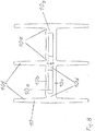
- two contact rails 11, 12 are provided for the potential or ground contact. It is basically irrelevant whether the two in Fig. 6 PTC heater 20 shown are arranged in the same heat-conducting body or in two different heat-conducting bodies. This means that the tank heaters can be expanded as required.
- Fig. 7 two in the Figures 4 and 5 illustrated heat-conducting body arranged in a single housing 1, 2 and electrically connected via the contact rails 11, 12. If only one heat-conducting body 10 is present and this is used for grounding the PTC heater 20, a single contact rail is sufficient, since the PTC heater 20 then only needs a single contact plate.
- the contact rails 11, 12 have openings into which extensions of the contact plates 14, 15 of the PTC heater are inserted and thus bring about an electrical contact. These openings can be formed by clamping tabs 11a, 12a bent out of the contact rails 11, 12.
- the two contact rails 11, 12 are held by a holder 13 made of plastic, which in Figure 4 you can see.
- the holder can be formed by injection molding around one or more contact rails 11, 12 or can be a separate plastic part which is attached to the contact rails 11, 12 by being plugged on.
- Fig. 7 shows a section of another embodiment of a tank heater, which is larger than the tank heater described above and has a larger number of cooling fins.
- the cover 2 of the plastic housing of this tank heater therefore has attachment lugs 9.
- the tank heater can thus on the one hand via the Fig. 6 Ring wall, not shown, of the lid 2 are welded and additionally fixed to a tank wall via the fastening lugs 9, for example by latching or welding.
- the lid can have attachment lugs for attaching or holding further components such as sensors, intake pipes, filters, etc.
- the cover 2 In order to fix the cover 2 to the lower part 1 of the plastic housing until it is welded, the cover 2 can have latching hooks 21 for latching to the lower part 1.
- the tank heater can be constructed like the tank heater described above.
- Fig. 8 only shows the heat-conducting body 10 with ribs 10f, a connecting base 10g and, for the PTC heaters 20, chambers 10a arranged in the base 10g.
- Such has side walls 10d running across a contact plate of the PTC heater, as well as a bottom wall 10c and a top wall 10b.
- the side walls 10d preferably have a thickness that is greater than the thickness of the bottom wall 10c and greater than the thickness of the top wall 10b.
- the side walls 10g facing an adjacent chamber 10a extend over their entire height h from one chamber 10a to the adjacent chamber 10a.
- the contact plates 14, 15 of the PTC heater 20 and the associated contact rails 11, 12 can also be arranged below the base without lateral angling, which advantageously simplifies production.
- the heat-conducting body 10 has a limiting groove 10e on both sides of the chambers 10a on the ceiling wall 10b. They limit the pressing pressure.
Landscapes
- Air-Conditioning For Vehicles (AREA)
Applications Claiming Priority (1)
| Application Number | Priority Date | Filing Date | Title |
|---|---|---|---|
| DE102018117329.6A DE102018117329A1 (de) | 2018-07-18 | 2018-07-18 | Tankheizung |
Publications (2)
| Publication Number | Publication Date |
|---|---|
| EP3597878A1 true EP3597878A1 (fr) | 2020-01-22 |
| EP3597878B1 EP3597878B1 (fr) | 2022-05-18 |
Family
ID=67314661
Family Applications (1)
| Application Number | Title | Priority Date | Filing Date |
|---|---|---|---|
| EP19186526.0A Active EP3597878B1 (fr) | 2018-07-18 | 2019-07-16 | Chauffage de citerne |
Country Status (2)
| Country | Link |
|---|---|
| EP (1) | EP3597878B1 (fr) |
| DE (1) | DE102018117329A1 (fr) |
Citations (5)
| Publication number | Priority date | Publication date | Assignee | Title |
|---|---|---|---|---|
| DE102009046954A1 (de) * | 2009-11-23 | 2011-05-26 | Robert Bosch Gmbh | Modulkonzept für die Komponenten eines Tanks zur Bevorratung eines Reduktionsmittels |
| DE102011084962A1 (de) * | 2011-10-21 | 2013-04-25 | Robert Bosch Gmbh | Tankheizung, insbesondere für einen Reduktionsmitteltank einer Brennkraftmaschine |
| EP2650497A1 (fr) | 2012-04-11 | 2013-10-16 | TI Automotive Fuel Systems SAS | Système permettant de stocker une solution additive pour un moteur de véhicule |
| DE102014108074A1 (de) * | 2014-06-06 | 2015-12-17 | Dbk David + Baader Gmbh | Heizmodul und Tanksystem |
| DE102017103039B3 (de) * | 2017-02-15 | 2018-06-07 | Eichenauer Heizelemente Gmbh & Co. Kg | Heizeinheit zum Beheizen von Flüssigkeiten in einem Kraftfahrzeug |
Family Cites Families (2)
| Publication number | Priority date | Publication date | Assignee | Title |
|---|---|---|---|---|
| EP2341224B1 (fr) | 2009-12-24 | 2017-06-14 | DBK David + Baader GmbH | Réservoir chauffé, module de chauffage et système de réservoir |
| DE102011088659A1 (de) * | 2011-12-15 | 2013-06-20 | Robert Bosch Gmbh | Vorrichtung zum Befestigen eines Dosierventils |
-
2018
- 2018-07-18 DE DE102018117329.6A patent/DE102018117329A1/de not_active Withdrawn
-
2019
- 2019-07-16 EP EP19186526.0A patent/EP3597878B1/fr active Active
Patent Citations (5)
| Publication number | Priority date | Publication date | Assignee | Title |
|---|---|---|---|---|
| DE102009046954A1 (de) * | 2009-11-23 | 2011-05-26 | Robert Bosch Gmbh | Modulkonzept für die Komponenten eines Tanks zur Bevorratung eines Reduktionsmittels |
| DE102011084962A1 (de) * | 2011-10-21 | 2013-04-25 | Robert Bosch Gmbh | Tankheizung, insbesondere für einen Reduktionsmitteltank einer Brennkraftmaschine |
| EP2650497A1 (fr) | 2012-04-11 | 2013-10-16 | TI Automotive Fuel Systems SAS | Système permettant de stocker une solution additive pour un moteur de véhicule |
| DE102014108074A1 (de) * | 2014-06-06 | 2015-12-17 | Dbk David + Baader Gmbh | Heizmodul und Tanksystem |
| DE102017103039B3 (de) * | 2017-02-15 | 2018-06-07 | Eichenauer Heizelemente Gmbh & Co. Kg | Heizeinheit zum Beheizen von Flüssigkeiten in einem Kraftfahrzeug |
Also Published As
| Publication number | Publication date |
|---|---|
| EP3597878B1 (fr) | 2022-05-18 |
| DE102018117329A1 (de) | 2020-01-23 |
Similar Documents
| Publication | Publication Date | Title |
|---|---|---|
| EP3334246B1 (fr) | Dispositif de chauffage électrique | |
| EP2607121B1 (fr) | Dispositif de chauffage électrique, en particulier pour un véhicule automobile | |
| EP3079442B1 (fr) | Dispositif de chauffage électrique et cadre associé | |
| EP3101364B1 (fr) | Dispositif de chauffage électrique | |
| EP1375997B1 (fr) | Dispositiv de chauffage pour un conduit et procédé de construction | |
| EP2607808B1 (fr) | Elément générateur de chaleur | |
| EP1433994B1 (fr) | Dispositif de chauffage d'un conduit de gaz de carter et procéde de construction | |
| EP2884817B1 (fr) | Dispositif de chauffage électrique et son procédé de fabrication | |
| EP2608633A1 (fr) | Elément générateur de chaleur | |
| DD211090A5 (de) | Elektrische heizvorrichtung fuer die scheibenwaschfluessigkeit von kraftfahrzeugen | |
| DE102009058159B4 (de) | Filtereinrichtung für Fluide mit einer elektrischen Heizung und Heizung für eine Filtereinrichtung | |
| EP2126301A1 (fr) | Module de transfert pour une réduction catalytique sélective | |
| DE102004062605B4 (de) | Elektrische Heizeinrichtung zum Erwärmen von Flüssigkeit in einem Kraftfahrzeug und Flüssigkeitsbehälter mit einer derartigen Heizeinrichtung | |
| DE102010029594A1 (de) | Beheizbare Fluidentnahmevorrichtung | |
| DE102011056144C5 (de) | Vorrichtung zum Beheizen von Blowby Gasen | |
| DE102019204472A1 (de) | Wärmeerzeugendes Element und elektrische Heizvorrichtung enthaltend ein solches | |
| EP3537057A1 (fr) | Dispositif de chauffage électrique | |
| EP3557155B1 (fr) | Dispositif de chauffage électrique | |
| EP0581176A2 (fr) | Dispositif de réchauffage électrique pour carburant diesel | |
| EP3597878B1 (fr) | Chauffage de citerne | |
| WO2005107322A1 (fr) | Procede pour l'isolation electrique d'un element fonctionnel electrique et dispositif presentant des elements fonctionnels ainsi isoles | |
| EP3820245B1 (fr) | Dispositif de chauffage ptc et dispositif de chauffage électrique doté d'un tel dispositif de chauffage ptc et procédé de fabrication d'un dispositif de chauffage électrique | |
| DE102018221654A1 (de) | PTC-Heizelement und Verfahren zu dessen Herstellung | |
| EP3537849A1 (fr) | Chauffage de réservoir | |
| DE102023121384A1 (de) | Elektrische Heizvorrichtung |
Legal Events
| Date | Code | Title | Description |
|---|---|---|---|
| PUAI | Public reference made under article 153(3) epc to a published international application that has entered the european phase |
Free format text: ORIGINAL CODE: 0009012 |
|
| STAA | Information on the status of an ep patent application or granted ep patent |
Free format text: STATUS: THE APPLICATION HAS BEEN PUBLISHED |
|
| AK | Designated contracting states |
Kind code of ref document: A1 Designated state(s): AL AT BE BG CH CY CZ DE DK EE ES FI FR GB GR HR HU IE IS IT LI LT LU LV MC MK MT NL NO PL PT RO RS SE SI SK SM TR |
|
| AX | Request for extension of the european patent |
Extension state: BA ME |
|
| STAA | Information on the status of an ep patent application or granted ep patent |
Free format text: STATUS: REQUEST FOR EXAMINATION WAS MADE |
|
| 17P | Request for examination filed |
Effective date: 20200514 |
|
| RBV | Designated contracting states (corrected) |
Designated state(s): AL AT BE BG CH CY CZ DE DK EE ES FI FR GB GR HR HU IE IS IT LI LT LU LV MC MK MT NL NO PL PT RO RS SE SI SK SM TR |
|
| GRAP | Despatch of communication of intention to grant a patent |
Free format text: ORIGINAL CODE: EPIDOSNIGR1 |
|
| STAA | Information on the status of an ep patent application or granted ep patent |
Free format text: STATUS: GRANT OF PATENT IS INTENDED |
|
| RIC1 | Information provided on ipc code assigned before grant |
Ipc: H05B 3/06 20060101ALI20211123BHEP Ipc: H05B 3/82 20060101ALI20211123BHEP Ipc: F01N 3/20 20060101AFI20211123BHEP |
|
| INTG | Intention to grant announced |
Effective date: 20211210 |
|
| GRAS | Grant fee paid |
Free format text: ORIGINAL CODE: EPIDOSNIGR3 |
|
| GRAA | (expected) grant |
Free format text: ORIGINAL CODE: 0009210 |
|
| STAA | Information on the status of an ep patent application or granted ep patent |
Free format text: STATUS: THE PATENT HAS BEEN GRANTED |
|
| AK | Designated contracting states |
Kind code of ref document: B1 Designated state(s): AL AT BE BG CH CY CZ DE DK EE ES FI FR GB GR HR HU IE IS IT LI LT LU LV MC MK MT NL NO PL PT RO RS SE SI SK SM TR |
|
| REG | Reference to a national code |
Ref country code: GB Ref legal event code: FG4D Free format text: NOT ENGLISH |
|
| REG | Reference to a national code |
Ref country code: CH Ref legal event code: EP |
|
| REG | Reference to a national code |
Ref country code: IE Ref legal event code: FG4D Free format text: LANGUAGE OF EP DOCUMENT: GERMAN |
|
| REG | Reference to a national code |
Ref country code: DE Ref legal event code: R096 Ref document number: 502019004396 Country of ref document: DE |
|
| REG | Reference to a national code |
Ref country code: AT Ref legal event code: REF Ref document number: 1493269 Country of ref document: AT Kind code of ref document: T Effective date: 20220615 |
|
| REG | Reference to a national code |
Ref country code: LT Ref legal event code: MG9D |
|
| REG | Reference to a national code |
Ref country code: NL Ref legal event code: MP Effective date: 20220518 |
|
| PG25 | Lapsed in a contracting state [announced via postgrant information from national office to epo] |
Ref country code: SE Free format text: LAPSE BECAUSE OF FAILURE TO SUBMIT A TRANSLATION OF THE DESCRIPTION OR TO PAY THE FEE WITHIN THE PRESCRIBED TIME-LIMIT Effective date: 20220518 Ref country code: PT Free format text: LAPSE BECAUSE OF FAILURE TO SUBMIT A TRANSLATION OF THE DESCRIPTION OR TO PAY THE FEE WITHIN THE PRESCRIBED TIME-LIMIT Effective date: 20220919 Ref country code: NO Free format text: LAPSE BECAUSE OF FAILURE TO SUBMIT A TRANSLATION OF THE DESCRIPTION OR TO PAY THE FEE WITHIN THE PRESCRIBED TIME-LIMIT Effective date: 20220818 Ref country code: NL Free format text: LAPSE BECAUSE OF FAILURE TO SUBMIT A TRANSLATION OF THE DESCRIPTION OR TO PAY THE FEE WITHIN THE PRESCRIBED TIME-LIMIT Effective date: 20220518 Ref country code: LT Free format text: LAPSE BECAUSE OF FAILURE TO SUBMIT A TRANSLATION OF THE DESCRIPTION OR TO PAY THE FEE WITHIN THE PRESCRIBED TIME-LIMIT Effective date: 20220518 Ref country code: HR Free format text: LAPSE BECAUSE OF FAILURE TO SUBMIT A TRANSLATION OF THE DESCRIPTION OR TO PAY THE FEE WITHIN THE PRESCRIBED TIME-LIMIT Effective date: 20220518 Ref country code: GR Free format text: LAPSE BECAUSE OF FAILURE TO SUBMIT A TRANSLATION OF THE DESCRIPTION OR TO PAY THE FEE WITHIN THE PRESCRIBED TIME-LIMIT Effective date: 20220819 Ref country code: FI Free format text: LAPSE BECAUSE OF FAILURE TO SUBMIT A TRANSLATION OF THE DESCRIPTION OR TO PAY THE FEE WITHIN THE PRESCRIBED TIME-LIMIT Effective date: 20220518 Ref country code: ES Free format text: LAPSE BECAUSE OF FAILURE TO SUBMIT A TRANSLATION OF THE DESCRIPTION OR TO PAY THE FEE WITHIN THE PRESCRIBED TIME-LIMIT Effective date: 20220518 Ref country code: BG Free format text: LAPSE BECAUSE OF FAILURE TO SUBMIT A TRANSLATION OF THE DESCRIPTION OR TO PAY THE FEE WITHIN THE PRESCRIBED TIME-LIMIT Effective date: 20220818 |
|
| PG25 | Lapsed in a contracting state [announced via postgrant information from national office to epo] |
Ref country code: RS Free format text: LAPSE BECAUSE OF FAILURE TO SUBMIT A TRANSLATION OF THE DESCRIPTION OR TO PAY THE FEE WITHIN THE PRESCRIBED TIME-LIMIT Effective date: 20220518 Ref country code: PL Free format text: LAPSE BECAUSE OF FAILURE TO SUBMIT A TRANSLATION OF THE DESCRIPTION OR TO PAY THE FEE WITHIN THE PRESCRIBED TIME-LIMIT Effective date: 20220518 Ref country code: LV Free format text: LAPSE BECAUSE OF FAILURE TO SUBMIT A TRANSLATION OF THE DESCRIPTION OR TO PAY THE FEE WITHIN THE PRESCRIBED TIME-LIMIT Effective date: 20220518 Ref country code: IS Free format text: LAPSE BECAUSE OF FAILURE TO SUBMIT A TRANSLATION OF THE DESCRIPTION OR TO PAY THE FEE WITHIN THE PRESCRIBED TIME-LIMIT Effective date: 20220918 |
|
| PG25 | Lapsed in a contracting state [announced via postgrant information from national office to epo] |
Ref country code: SM Free format text: LAPSE BECAUSE OF FAILURE TO SUBMIT A TRANSLATION OF THE DESCRIPTION OR TO PAY THE FEE WITHIN THE PRESCRIBED TIME-LIMIT Effective date: 20220518 Ref country code: SK Free format text: LAPSE BECAUSE OF FAILURE TO SUBMIT A TRANSLATION OF THE DESCRIPTION OR TO PAY THE FEE WITHIN THE PRESCRIBED TIME-LIMIT Effective date: 20220518 Ref country code: RO Free format text: LAPSE BECAUSE OF FAILURE TO SUBMIT A TRANSLATION OF THE DESCRIPTION OR TO PAY THE FEE WITHIN THE PRESCRIBED TIME-LIMIT Effective date: 20220518 Ref country code: EE Free format text: LAPSE BECAUSE OF FAILURE TO SUBMIT A TRANSLATION OF THE DESCRIPTION OR TO PAY THE FEE WITHIN THE PRESCRIBED TIME-LIMIT Effective date: 20220518 Ref country code: DK Free format text: LAPSE BECAUSE OF FAILURE TO SUBMIT A TRANSLATION OF THE DESCRIPTION OR TO PAY THE FEE WITHIN THE PRESCRIBED TIME-LIMIT Effective date: 20220518 Ref country code: CZ Free format text: LAPSE BECAUSE OF FAILURE TO SUBMIT A TRANSLATION OF THE DESCRIPTION OR TO PAY THE FEE WITHIN THE PRESCRIBED TIME-LIMIT Effective date: 20220518 |
|
| REG | Reference to a national code |
Ref country code: DE Ref legal event code: R097 Ref document number: 502019004396 Country of ref document: DE |
|
| PG25 | Lapsed in a contracting state [announced via postgrant information from national office to epo] |
Ref country code: MC Free format text: LAPSE BECAUSE OF FAILURE TO SUBMIT A TRANSLATION OF THE DESCRIPTION OR TO PAY THE FEE WITHIN THE PRESCRIBED TIME-LIMIT Effective date: 20220518 |
|
| REG | Reference to a national code |
Ref country code: CH Ref legal event code: PL |
|
| PLBE | No opposition filed within time limit |
Free format text: ORIGINAL CODE: 0009261 |
|
| STAA | Information on the status of an ep patent application or granted ep patent |
Free format text: STATUS: NO OPPOSITION FILED WITHIN TIME LIMIT |
|
| REG | Reference to a national code |
Ref country code: BE Ref legal event code: MM Effective date: 20220731 |
|
| PG25 | Lapsed in a contracting state [announced via postgrant information from national office to epo] |
Ref country code: AL Free format text: LAPSE BECAUSE OF FAILURE TO SUBMIT A TRANSLATION OF THE DESCRIPTION OR TO PAY THE FEE WITHIN THE PRESCRIBED TIME-LIMIT Effective date: 20220518 |
|
| 26N | No opposition filed |
Effective date: 20230221 |
|
| PG25 | Lapsed in a contracting state [announced via postgrant information from national office to epo] |
Ref country code: LU Free format text: LAPSE BECAUSE OF NON-PAYMENT OF DUE FEES Effective date: 20220716 Ref country code: LI Free format text: LAPSE BECAUSE OF NON-PAYMENT OF DUE FEES Effective date: 20220731 Ref country code: CH Free format text: LAPSE BECAUSE OF NON-PAYMENT OF DUE FEES Effective date: 20220731 |
|
| PG25 | Lapsed in a contracting state [announced via postgrant information from national office to epo] |
Ref country code: SI Free format text: LAPSE BECAUSE OF FAILURE TO SUBMIT A TRANSLATION OF THE DESCRIPTION OR TO PAY THE FEE WITHIN THE PRESCRIBED TIME-LIMIT Effective date: 20220518 Ref country code: BE Free format text: LAPSE BECAUSE OF NON-PAYMENT OF DUE FEES Effective date: 20220731 |
|
| PG25 | Lapsed in a contracting state [announced via postgrant information from national office to epo] |
Ref country code: IE Free format text: LAPSE BECAUSE OF NON-PAYMENT OF DUE FEES Effective date: 20220716 |
|
| PG25 | Lapsed in a contracting state [announced via postgrant information from national office to epo] |
Ref country code: IT Free format text: LAPSE BECAUSE OF FAILURE TO SUBMIT A TRANSLATION OF THE DESCRIPTION OR TO PAY THE FEE WITHIN THE PRESCRIBED TIME-LIMIT Effective date: 20220518 |
|
| GBPC | Gb: european patent ceased through non-payment of renewal fee |
Effective date: 20230716 |
|
| PG25 | Lapsed in a contracting state [announced via postgrant information from national office to epo] |
Ref country code: HU Free format text: LAPSE BECAUSE OF FAILURE TO SUBMIT A TRANSLATION OF THE DESCRIPTION OR TO PAY THE FEE WITHIN THE PRESCRIBED TIME-LIMIT; INVALID AB INITIO Effective date: 20190716 |
|
| PG25 | Lapsed in a contracting state [announced via postgrant information from national office to epo] |
Ref country code: MK Free format text: LAPSE BECAUSE OF FAILURE TO SUBMIT A TRANSLATION OF THE DESCRIPTION OR TO PAY THE FEE WITHIN THE PRESCRIBED TIME-LIMIT Effective date: 20220511 Ref country code: CY Free format text: LAPSE BECAUSE OF FAILURE TO SUBMIT A TRANSLATION OF THE DESCRIPTION OR TO PAY THE FEE WITHIN THE PRESCRIBED TIME-LIMIT Effective date: 20220511 Ref country code: GB Free format text: LAPSE BECAUSE OF NON-PAYMENT OF DUE FEES Effective date: 20230716 |
|
| PG25 | Lapsed in a contracting state [announced via postgrant information from national office to epo] |
Ref country code: MT Free format text: LAPSE BECAUSE OF FAILURE TO SUBMIT A TRANSLATION OF THE DESCRIPTION OR TO PAY THE FEE WITHIN THE PRESCRIBED TIME-LIMIT Effective date: 20220511 |
|
| PG25 | Lapsed in a contracting state [announced via postgrant information from national office to epo] |
Ref country code: BG Free format text: LAPSE BECAUSE OF FAILURE TO SUBMIT A TRANSLATION OF THE DESCRIPTION OR TO PAY THE FEE WITHIN THE PRESCRIBED TIME-LIMIT Effective date: 20220518 |
|
| PG25 | Lapsed in a contracting state [announced via postgrant information from national office to epo] |
Ref country code: BG Free format text: LAPSE BECAUSE OF FAILURE TO SUBMIT A TRANSLATION OF THE DESCRIPTION OR TO PAY THE FEE WITHIN THE PRESCRIBED TIME-LIMIT Effective date: 20220518 |
|
| REG | Reference to a national code |
Ref country code: AT Ref legal event code: MM01 Ref document number: 1493269 Country of ref document: AT Kind code of ref document: T Effective date: 20240716 |
|
| PGFP | Annual fee paid to national office [announced via postgrant information from national office to epo] |
Ref country code: DE Payment date: 20250731 Year of fee payment: 7 |
|
| PG25 | Lapsed in a contracting state [announced via postgrant information from national office to epo] |
Ref country code: AT Free format text: LAPSE BECAUSE OF NON-PAYMENT OF DUE FEES Effective date: 20240716 |
|
| PGFP | Annual fee paid to national office [announced via postgrant information from national office to epo] |
Ref country code: FR Payment date: 20250731 Year of fee payment: 7 |
|
| PG25 | Lapsed in a contracting state [announced via postgrant information from national office to epo] |
Ref country code: TR Free format text: LAPSE BECAUSE OF FAILURE TO SUBMIT A TRANSLATION OF THE DESCRIPTION OR TO PAY THE FEE WITHIN THE PRESCRIBED TIME-LIMIT Effective date: 20220518 |
|
| PGFP | Annual fee paid to national office [announced via postgrant information from national office to epo] |
Ref country code: AT Payment date: 20260410 Year of fee payment: 5 |