EP3597882A1 - Moteur à piston rotatif - Google Patents
Moteur à piston rotatif Download PDFInfo
- Publication number
- EP3597882A1 EP3597882A1 EP19179598.8A EP19179598A EP3597882A1 EP 3597882 A1 EP3597882 A1 EP 3597882A1 EP 19179598 A EP19179598 A EP 19179598A EP 3597882 A1 EP3597882 A1 EP 3597882A1
- Authority
- EP
- European Patent Office
- Prior art keywords
- rotor
- side area
- rotation direction
- leading
- rotor housing
- Prior art date
- Legal status (The legal status is an assumption and is not a legal conclusion. Google has not performed a legal analysis and makes no representation as to the accuracy of the status listed.)
- Granted
Links
Images


Classifications
-
- F—MECHANICAL ENGINEERING; LIGHTING; HEATING; WEAPONS; BLASTING
- F01—MACHINES OR ENGINES IN GENERAL; ENGINE PLANTS IN GENERAL; STEAM ENGINES
- F01C—ROTARY-PISTON OR OSCILLATING-PISTON MACHINES OR ENGINES
- F01C1/00—Rotary-piston machines or engines
- F01C1/22—Rotary-piston machines or engines of internal-axis type with equidirectional movement of co-operating members at the points of engagement, or with one of the co-operating members being stationary, the inner member having more teeth or tooth- equivalents than the outer member
-
- F—MECHANICAL ENGINEERING; LIGHTING; HEATING; WEAPONS; BLASTING
- F02—COMBUSTION ENGINES; HOT-GAS OR COMBUSTION-PRODUCT ENGINE PLANTS
- F02B—INTERNAL-COMBUSTION PISTON ENGINES; COMBUSTION ENGINES IN GENERAL
- F02B55/00—Internal-combustion aspects of rotary pistons; Outer members for co-operation with rotary pistons
- F02B55/02—Pistons
-
- F—MECHANICAL ENGINEERING; LIGHTING; HEATING; WEAPONS; BLASTING
- F01—MACHINES OR ENGINES IN GENERAL; ENGINE PLANTS IN GENERAL; STEAM ENGINES
- F01C—ROTARY-PISTON OR OSCILLATING-PISTON MACHINES OR ENGINES
- F01C21/00—Component parts, details or accessories not provided for in groups F01C1/00 - F01C20/00
- F01C21/08—Rotary pistons
-
- F—MECHANICAL ENGINEERING; LIGHTING; HEATING; WEAPONS; BLASTING
- F02—COMBUSTION ENGINES; HOT-GAS OR COMBUSTION-PRODUCT ENGINE PLANTS
- F02B—INTERNAL-COMBUSTION PISTON ENGINES; COMBUSTION ENGINES IN GENERAL
- F02B53/00—Internal-combustion aspects of rotary-piston or oscillating-piston engines
- F02B53/12—Ignition
-
- F—MECHANICAL ENGINEERING; LIGHTING; HEATING; WEAPONS; BLASTING
- F02—COMBUSTION ENGINES; HOT-GAS OR COMBUSTION-PRODUCT ENGINE PLANTS
- F02B—INTERNAL-COMBUSTION PISTON ENGINES; COMBUSTION ENGINES IN GENERAL
- F02B55/00—Internal-combustion aspects of rotary pistons; Outer members for co-operation with rotary pistons
- F02B55/08—Outer members for co-operation with rotary pistons; Casings
-
- F—MECHANICAL ENGINEERING; LIGHTING; HEATING; WEAPONS; BLASTING
- F02—COMBUSTION ENGINES; HOT-GAS OR COMBUSTION-PRODUCT ENGINE PLANTS
- F02B—INTERNAL-COMBUSTION PISTON ENGINES; COMBUSTION ENGINES IN GENERAL
- F02B53/00—Internal-combustion aspects of rotary-piston or oscillating-piston engines
- F02B2053/005—Wankel engines
-
- F—MECHANICAL ENGINEERING; LIGHTING; HEATING; WEAPONS; BLASTING
- F02—COMBUSTION ENGINES; HOT-GAS OR COMBUSTION-PRODUCT ENGINE PLANTS
- F02B—INTERNAL-COMBUSTION PISTON ENGINES; COMBUSTION ENGINES IN GENERAL
- F02B2730/00—Internal-combustion engines with pistons rotating or oscillating with relation to the housing
- F02B2730/01—Internal-combustion engines with pistons rotating or oscillating with relation to the housing with one or more pistons in the form of a disk or rotor rotating with relation to the housing; with annular working chamber
-
- F—MECHANICAL ENGINEERING; LIGHTING; HEATING; WEAPONS; BLASTING
- F02—COMBUSTION ENGINES; HOT-GAS OR COMBUSTION-PRODUCT ENGINE PLANTS
- F02B—INTERNAL-COMBUSTION PISTON ENGINES; COMBUSTION ENGINES IN GENERAL
- F02B55/00—Internal-combustion aspects of rotary pistons; Outer members for co-operation with rotary pistons
- F02B55/14—Shapes or constructions of combustion chambers
-
- F—MECHANICAL ENGINEERING; LIGHTING; HEATING; WEAPONS; BLASTING
- F04—POSITIVE - DISPLACEMENT MACHINES FOR LIQUIDS; PUMPS FOR LIQUIDS OR ELASTIC FLUIDS
- F04C—ROTARY-PISTON, OR OSCILLATING-PISTON, POSITIVE-DISPLACEMENT MACHINES FOR LIQUIDS; ROTARY-PISTON, OR OSCILLATING-PISTON, POSITIVE-DISPLACEMENT PUMPS
- F04C2250/00—Geometry
- F04C2250/20—Geometry of the rotor
-
- Y—GENERAL TAGGING OF NEW TECHNOLOGICAL DEVELOPMENTS; GENERAL TAGGING OF CROSS-SECTIONAL TECHNOLOGIES SPANNING OVER SEVERAL SECTIONS OF THE IPC; TECHNICAL SUBJECTS COVERED BY FORMER USPC CROSS-REFERENCE ART COLLECTIONS [XRACs] AND DIGESTS
- Y02—TECHNOLOGIES OR APPLICATIONS FOR MITIGATION OR ADAPTATION AGAINST CLIMATE CHANGE
- Y02T—CLIMATE CHANGE MITIGATION TECHNOLOGIES RELATED TO TRANSPORTATION
- Y02T10/00—Road transport of goods or passengers
- Y02T10/10—Internal combustion engine [ICE] based vehicles
- Y02T10/12—Improving ICE efficiencies
Definitions
- the present disclosure relates to a rotary piston engine.
- a combustion chamber is defined between a rotor housing with a trochoid inner circumferential surface and a rotor.
- a recess for defining the combustion chamber is formed in the outer circumferential surface of the rotor.
- Japanese Unexamined Patent Publication No. 2015-78664 describes a recess including a first recess and a second recess. The first recess is located on the trailing side in the rotation direction of a rotor. The second recess is located on the leading side and continuous with the first recess.
- the cross-sectional area of the first recess which is orthogonal to the circumference of the rotor, is smaller than that of the second recess. This improves the combustion stability of the engine. Specifically, when air-fuel mixture flows from the trailing side to the leading side, generation of turbulence is facilitated at the connection between the first and second recesses, at which the cross-sectional area of the whole recess changes. This aims to promote mixture and diffusion of the air-fuel mixture.
- a known problem in a rotary piston engine is that the combustion center of gravity retards at introduction of EGR gas, and the thermal efficiency decreases.
- advancing of ignition timing and shortening of the period of ignition delay i.e., the period from ignition to start of apparent heat generation
- a rotary piston engine has the following tendency due to the structure, unlike a reciprocating engine. More heat tends to be transferred from flame to the wall surface of the combustion chamber at an initial stage of combustion after ignition. It is thus difficult to exhibit robustness of ignition in advanced ignition, and to shorten the period of ignition delay.
- the present disclosure enables advanced ignition and a shorter period of ignition delay in a rotary piston engine to improve thermal efficiency with advanced combustion center of gravity.
- the position of the recess in the outer circumferential surface of a rotor is shifted to the leading side to increase the volume of a leading-side area relative to that of a trailing-side area.
- a rotary piston engine disclosed herein includes: a rotor housing with a trochoid inner circumferential surface; a substantially triangular rotor housed in the rotor housing chamber, having three outer circumferential surfaces that partition the rotor housing chamber into three operation chambers, having recesses, each being formed in one of the outer circumferential surfaces, and allowing the operation chambers to sequentially perform intake, compression, expansion and exhaust strokes while circumferentially moving the operation chambers by rotation; and a spark plug provided in the rotor housing.
- Each of the recesses includes: a leading-side area extending forward from a longitudinal center of the associated one of the outer circumferential surfaces in a rotation direction of the rotor, and a trailing-side area continuous with the leading-side area, and extending rearward from the longitudinal center in the rotation direction.
- leading-side area From the longitudinal center in the rotation direction, forward extension of the leading-side area is longer than rearward extension of the trailing-side area.
- the leading-side area has a larger volume than the trailing-side area.
- the leading-side area extends longer from the longitudinal center, of the outer circumferential face of the rotor, in the rotation direction of the rotor. This allows a flame to grow in the leading-side area, while largely advancing ignition timing from a compression top dead center. In the growth of the flame in the leading-side area, since the leading-side area has a large volume, the heat transferred from the flame to wall surfaces due to the contact between the flame and the rotor, that is, a cooling loss decreases. This facilitates the growth of the flame at the initial stage of combustion.
- a distance between a distal end of the leading-side area in the rotation direction and a tip of the associated one of the outer circumferential surfaces in the rotation direction falls within a range from 5/100 to 15/100 of a length of the outer circumferential surface in the rotation direction.
- the leading-side area includes a recessed depth that is deepest at a center corresponding to an ignition point of the spark plug.
- the depth is deeper than the trailing-side area, and has a concave surface curving with a depth gradually decreasing toward both sides of the associated one of the outer circumferential surfaces of the rotor and toward a front in the rotation direction.
- Each of the recesses includes: a leading-side area extending forward from a longitudinal center of an associated one of the outer circumferential surfaces in a rotation direction of the rotor, and a trailing-side area continuous with the leading-side area, and extending rearward from the longitudinal center in the rotation direction.
- Each of the recesses extends long in the rotation direction.
- the leading-side area has a width gently increasing toward a front in the rotation direction of the rotor, and an arc-like distal end.
- the trailing-side area is continuous with a narrowed proximal end of the leading-side area, extends, with a same width as the proximal end, rearward in the rotation direction of the rotor, and has a tapered distal end and a distal edge that extends linearly along a width of the rotor.
- a distance between the distal end of the leading-side area in the rotation direction of the rotor and a tip of the outer circumferential surface in the rotation direction falls within a range from 5/100 to 15/100 of a length of the outer circumferential surface in the rotation direction.
- the leading-side area has a larger volume than the trailing-side area.
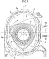
- a rotary piston engine 1 (hereinafter simply referred to as an engine 1) shown in FIG. 1 is mounted on a vehicle, and includes two rotors 2.
- An intermediate housing 4 is provided between two rotor housings 3, each of which houses one of the rotors 2.
- Side housings 5 are provided, each of which is located on the outer side of either one of the two rotor housings 3. Focusing on one rotor housing 3, the intermediate housing 4 may be positioned on one side of the rotor housing 3. Together with the rotor housing 3 and one of the side housings 5, the intermediate housing 4 may be regarded as a side housing forming one of rotor housing chambers 31.
- FIG. 1 the front (right in FIG. 1 ) of the engine 1 partially is cut out to show the inside of the engine, and the side housing 5 to the rear (left in FIG. 1 ) is shown separately to show the inside of the engine 1.
- Reference character X in the figure indicates the rotation axis of an eccentric shaft as an output shaft.
- each rotor housing 3 has a trochoid inner circumferential surface 3a in a substantially elliptical (oval) shape as viewed along the rotation axis X, which is drawn by a parallel trochoid curve.
- the inner circumferential surface of each rotor housing 3, a side surface 4a on one side of the intermediate housing 4, and an inner side surface 5a of an associated one of the side housings 5 define one of the rotor housing chambers 31.
- This rotor housing chamber 31 houses one of the rotors 2.
- the two rotor housing chambers 31 on the sides of the intermediate housing 4 have the same configuration except that the respective rotors 2 rotate with different phases.
- Each rotor 2 is in a substantially triangular shape with sides whose centers expand outside as viewed along the rotation axis X. Between each pair of apexes of the triangle, an outer circumferential surface 2a in a substantially rectangular shape is found, in which a recess 7 is formed. An apex seal 9 provided on each apex of the triangle of each rotor 2 comes into sliding contact with the trochoid inner peripheral surface 3a of the associated one of the rotor housings 3 in accordance with the rotation of the rotor 2. As shown in FIG. 2 , the rotor 2 partitions the inside of the rotor housing chamber 31 into three operation chambers 8.
- the rotor 2 is supported by an eccentric ring 6a of an eccentric shaft 6. While rotating, the rotor 2 revolves about the rotation axis X in the same direction as the rotation. The rotation of the rotor 2 includes these rotation and revolution in a broad sense. While the rotor 2 rotates once, the three operation chambers 8 move circumferentially to perform intake, compression, expansion (combustion), and exhaust strokes. The rotational force generated thereby is output from the eccentric shaft 6 via the rotor 2.
- the rotor 2 rotates clockwise as indicated by the arrow.
- the rotor housing chamber 31 is divided into right and left by the longer axis Y of the rotor housing chamber 31, which passes through the rotation axis X.
- the left of the rotor housing chamber 31 substantially serves as a region for the intake and exhaust strokes.
- the right substantially serves as a region for the compression and expansion strokes.
- intake ports 11 to 13 and exhaust ports 10 are open in the positions corresponding to the regions for the intake and exhaust strokes on the side surfaces 4a of the intermediate housing 4 and the inner side surfaces 5a of the side housings 5.
- each of fuel injection valves for injecting fuel into the respective operation chambers 8 performing the intake or compression stroke is provided on the top of the associated one of the rotor housings 3.
- a leading spark plug 91 (hereinafter referred to as an "L-side spark plug 91") is attached to the side of the rotor housing 3 on the leading side.
- a trailing spark plug 92 (hereinafter, referred to as a "T-side spark plug 92") is attached to the side of the rotor housing 3 on the trailing side.
- the longer axis Y and the shorter axis Z are orthogonal to each other.
- the rotary piston engine 1 includes an EGR system that returns part of exhaust gas to intake passages.
- the exhaust gas circulates in accordance with the operating state of the engine.
- the rotary piston engine 1 includes a control unit as a controller for controlling the operation of the engine, including intake throttle valves, fuel injection valves, the spark plugs 91 and 92, and the EGR system.
- the control unit includes a microcomputer as a base, a central processing unit (CPU), a memory, and a signal input/output (I/O) bus.
- the CPU executes programs.
- the memory may be, for example, a RAM or a ROM that stores the programs and data.
- the control unit receives signals of various information from an accelerator position sensor, a vehicle speed sensor, an engine rotation angle sensor, an air-fuel ratio sensor, an engine water temperature sensor, an air flow sensor, and other sensors of the vehicle.
- the control unit determines the operating state of the engine 1 based on the received signals. In accordance with the operating state, the control unit controls the opening degrees of the throttle valves, the EGR rate of the EGR system, the ignition timings of the Land T-side spark plugs 91 and 92, and the amounts and timings of fuel injection by the fuel injection valves in respective operation chambers 8.
- the ignition timing of the L-side spark plug 91 is more advanced than the ignition timing of the T-side spark plug 92 within a range from 15° to 55° before a compression top dead center (BTDC). Based on this setting, the times for conducting electricity to L- and T-side spark coils are controlled.
- BTDC compression top dead center
- the ignition timing of the L-side spark plug 91 is controlled in accordance with the EGR ratio so that the combustion center of gravity is brought to an appropriate position with high thermal efficiency within a range from 10° to 30° after the compression top dead center ATDC.
- the operation chamber located on the opposite side of the apex reaches a compression top dead center.
- the period of ignition delay as well as a target start time of (apparent) heat generation is set in accordance with the EGR ratio. Accordingly, the timing advancing from the target start time of heat generation by the period of ignition delay is regarded as the ignition timing of the L-side spark plug 91.
- the ignition timing of the L-side spark plug 91 is corrected in accordance with the engine load (the opening degree of the throttle valve) and the engine speed. That is, the higher the engine load is, the more the ignition timing retards, while the higher the engine speed is, the more the ignition timing advances.
- the ignition timing by the T-side spark plug 92 is controlled to retard from the ignition timing of the L-side spark plug 91 by a predetermined angle.
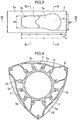
- the recess 7 formed in each of the outer circumferential surfaces 2a of the rotors 2 extends long in the rotation direction of the rotor 2.
- the recess 7 includes a leading-side area 7a (hereinafter referred to as an "L-side area 7a") and a trailing-side area 7b (hereinafter referred to as a "T-side area 7b").
- the L-side area 7a extends forward from the longitudinal center of the outer circumferential surface 2a in the rotation direction of the rotor.
- the T-side area 7b is continuous to the L-side area 7a and extends rearward from the center of the outer circumferential surface 2a in the rotation direction of the rotor.
- the volume of the recess 7 is set such that each operation chamber 8 has a geometric compression ratio of 9.7 or greater.
- the L-side area 7a has a width gently increasing toward the front in the rotation direction of the rotor.
- the distal end of the L-side area 7a is in an arc shape.
- the L-side area 7a is in a shape expanding forward in the rotation direction of the rotor like a bulb.
- the T-side area 7b is continuous with the narrowed proximal end of the L-side area 7a, and extends, with the same width as the proximal end, rearward in the rotation direction of the rotor.
- the T-side area 7b has a tapered distal end, and a distal edge that extends linearly along the width of the rotor 2.
- the L-side area 7a extends forward in the rotation direction of the rotor from the longitudinal center of the outer circumferential surface 2a.
- the T-side area 7b extends rearward in the rotation direction of the rotor from the longitudinal center of the outer circumferential face 2b.
- the L-side area 7a has a forward extension L1 longer than a rearward extension L2 of the T-side area 7b.
- a distance Ld between the distal end of the L-side area 7a in the rotation direction of the rotor and the tip of the outer circumferential surface of the L-side area 7a in the rotation direction falls within a range from 5/100 to 15/100 of a length Lo of the outer circumferential surface 2a in the rotation direction of the rotor.
- the Ld/Lo ratio falls within a range from 5/100 to 12/100 to exhibit a lower S/V ratio, which will be described later, than that in Comparative Example 1. In one more preferred embodiment, the Ld/Lo ratio falls within a range from 7/100 to 10/100 to obtain a low S/V ratio at 49° BTDC.
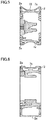
- the L-side area 7a includes a depth 15, which is recessed to be deepest at the center corresponding to the ignition point of the L-side spark plug 91.
- the depth 15 is deeper than the T-side area 7b.
- the depth 15 has a concave surface curving with a depth gradually decreasing toward both the sides of the outer circumferential surface 2a of the rotor 2 and toward the front in the rotation direction of the rotor.
- the depth 15 has a width W1 larger than a width W2 of the T-side area 7b, and larger than the diameter of a hemispherical bulge of a virtual flame, which will be described later.
- the depth 15 has a larger radius of curvature than the hemispherical bulge thereof.
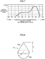
- FIG. 7 illustrates a change in the cross-sectional area, which is perpendicular to the rotation direction of the rotor, of each recess 7 along the length of the associated one of the outer circumferential surfaces 2a of the rotors 2.
- the L-side area 7a has a small cross-sectional area that is substantially constant, as viewed forward in the rotation direction of the rotor, from the longitudinal center of the outer circumferential surface 2a to the area around 20/100 of the entire leading-side length.
- the entire leading-side length extends from the longitudinal center of the outer circumferential surface 2a to the front end. After reaching the area around 20/100, the cross-sectional area gradually increases. After reaching the area around 50/100 of the entire leading-side length, the cross-sectional area becomes the largest, and then gradually decreases.
- the T-side area 7b has a cross-sectional area that is substantially the same as the small cross-sectional area of the L-side area 7a, as viewed rearward in the rotation direction of the rotor, from the longitudinal center of the outer circumferential surface 2a to the area around 20/100 or 30/100 of the entire trailing-side length.
- the entire trailing-side length extends from the longitudinal center of the outer circumferential surface 2a to the rear end. After reaching the area around 20/100 or 30/100, the cross-sectional area gradually decreases.
- the L-side area 7a has the following cross-sectional area in one preferred embodiment.
- the cross-sectional area starts increasing at a point within a range from 15/100 to 30/100 of the entire leading-side length from the longitudinal center of the outer circumferential surface 2a.
- the cross-sectional area is the largest at a point within a range from 50/100 to 70/100 of the entire leading-side length. This is to provide a low S/V ratio at 49° BTDC.
- a volume V1 of the L-side area 7a is larger than a volume V2 of the T-side area 7b.
- the volume ratio V1/V2 falls within a range from 60/40 to 80/20 in one preferred embodiment.
- the L-side spark plug 91 ignites air-fuel mixture before the compression top dead center. While a flame radially propagates from the ignition point, the center of the flame moves in the rotation direction of the rotor due to a squish flow from the trailing side to the leading side caused by a change in the volume of the operation chamber 8.
- An ideal shape of the flame generated in this case is as follows on the assumption that neither the rotor 2 nor the rotor housing 3 interferes with the flame. As shown in FIG. 8 , the flame conically expands from the ignition point in the moving direction. The tip surface of the flame hemispherically bulges.
- the flame has an integrated shape of a cone 16a and a hemispherical bulge 16b, where the center of the flame moves at a distance L, and the flame propagates at distance r from the center of the flame.
- the cone 16a has a bottom with a diameter of 2 ⁇ r, and a height of L, while the hemispherical bulge 16b has a radius r.
- a virtual flame 16 is generated when the L-side spark plug 91 ignites air-fuel mixture before the compression top dead center.
- the virtual flame 16 includes the cone 16a with a length L of 17.5 mm, and the hemispherical bulge 16b with a radius r of 12.5 mm.
- the volume of the virtual flame 16 is the sum of the volume of the cone 16a (1/3 ⁇ ⁇ r 2 ⁇ L) and the volume of the hemispherical bulge 16b (2/3 ⁇ ⁇ r 3 ). This virtual flame is assumed to be formed at the start time of the apparent heat generation.
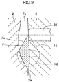
- each of the recesses 7 in the outer circumferential surfaces 2a of the rotors 2 will be described based on the geometric interference of the rotor 2 and the rotor housing 3 with the virtual flame 16 at 49° BTDC shown in FIG. 9 .
- the rotor 2 and the rotor housing 3 geometrically interfere with the virtual flame 16 at 49° BTDC.
- the part (hatched with broken lines in FIG. 9 ) of the virtual flame 16, which is not interfered with by the rotor 2 or the rotor housing 3, has a volume V (mm 3 ) (hereinafter referred to as a "non-interference volume").
- the total area of the surfaces on which the virtual flame 16 is in contact with the rotor 2 and the rotor housing 3 is S (mm 2 ). That is, the total area is the sum of the contact areas between the part with the non-interference volume V and the rotor 2 and between the non-interference volume V and the rotor housing 3 (hereinafter referred to as a "contact area").
- the non-interference volume V of the virtual flame 16 is deprived of heat from the surfaces (the parts of the contact area S), which are in contact with the rotor 2 and the rotor housing 3, by the rotor 2 and the rotor housing 3. This is a cooling loss. In this case, with an increase in the contact area S relative to the non-interference volume V, the cooling loss also increases.
- definition of the S/V ratio which is the ratio of the contact area S to the non-interference volume V, allows for estimate of the degree of the cooling loss at the initial stage of combustion of the rotary piston engine based on the virtual flame 16.
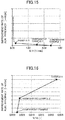
- the S/V ratio is 0.45 or lower in one preferred embodiment.
- the S/V ratio of 0.45 or lower means a small cooling loss from the flame at the initial stage of combustion.
- FIG. 10 illustrates the rotor 2 at 24° BTDC.
- the virtual flame 16 extends forward in the rotation direction of the rotor.
- the depth 15 described above is formed in a forward position of the L-side area 7a to increase the cross-sectional area of the depth 15, thereby reducing the interference between the flame and the rotor 2.
- the rotor 2 interferes less with the virtual flame 16.
- the interference of the rotor housing 3 is still unchanged. Specifically, the rotor housing 3 interferes with a half of the virtual flame 16 when the virtual flame 16 is divided by the vertical section passing through the axis of the conical expansion.
- V 1/2 ⁇ (1/3 ⁇ ⁇ r 2 ⁇ L + 2/3 ⁇ ⁇ r 3 ) holds.
- the lower limit of the S/V ratio is about 0.13 in one preferred embodiment.
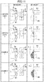
- FIGS. 11 and 12 rotors according to Examples 1 to 6 and Comparative Examples 1 and 2 having recesses with difference configurations were prepared.
- each of the left views of Examples 1 to 6 and Comparative Examples 1 and 2 illustrates the relationship between the rotor 2 and the spark plugs 91 and 92 at 49° BTDC.
- On the right enlarged views around the respective L-side spark plugs 91 are found, each of which illustrates the relationship between the operation chamber 8 and the virtual flame 16.
- a white circle and a black dot in the recess 7 shown on the right represent the positions of the L-side spark plug 91 and the T-side spark plug 91, respectively.
- Comparative Example 1 a dish-shaped rectangular recess 7 with a substantially constant depth is formed in the outer circumferential surface of the rotor 2.
- the volume ratio V1/V2 of the L-side area to the T-side area is 50/50.
- the rotor 2 since the distal end of the L-side area is located near the L-side spark plug 91, the rotor 2 interferes more with the virtual flame 16. This results in a high S/V ratio.
- Comparative Example 2 as compared to Comparative Example 1, the recess 7 is, as a whole, shifted forward in the rotation direction of the rotor.
- the distal end of the L-side area slightly expands forward in the rotation direction of the rotor.
- V1/V2 is 64/36.
- the total volume of the recess is slightly larger.
- the distal end of the L-side area bulges forward in small degree in the rotation direction of the rotor. This results in a high S/V ratio, as in Comparative Example 1.
- Example 1 as compared to Comparative Example 1, the recess 7 is elongate such that the distal end of the L-side area extends forward in the rotation direction of the rotor, and the depth is formed in a forward position of the L-side area. As a result, the rotor interferes less with the virtual flame, which decreases the S/V ratio. V1/V2 is 65/35.
- the recess has a slightly larger total volume than that of Comparative Example 1.
- Example 2 as compared to Comparative Example 1, the recess 7 is elongate such that the distal end of the L-side area extends forward in the rotation direction of the rotor, and the recess is deep as a whole. As a result, the rotor interferences less with the virtual flame, which decreases the S/V ratio. V1/V2 is 64/36. The recess has a slightly larger total volume than that of Comparative Example 1.
- Example 3 as compared to Comparative Example 1, the T-side area is narrow and the distal end of the L-side area extends forward in the rotation direction of the rotor, and the depth is formed in a forward position of the L-side area. As a result, the rotor interferes less with the virtual flame, which decreases the S/V ratio. V1/V2 is 65/35. The recess has a slightly larger total volume than that of Comparative Example 1.
- Example 4 as compared to Comparative Example 1, the recess 7 is elongate such that the distal end of the L-side area extends forward in the rotation direction of the rotor. As a result, the rotor interferes less with the virtual flame, which decreases the S/V ratio. However, since the L-side area has no depth, this example exhibits a higher S/V ratio than that of Example 1. V1/V2 is 64/36. The recess has a slightly larger total volume than that of Comparative Example 1.
- Example 5 as compared to Comparative Example 1, the recess 7 is shifted forward in the rotation direction of the rotor. In addition, the distal end of the L-side area extends forward in the rotation direction of the rotor. As a result, the rotor interferes less with the virtual flame, which decreases the S/V ratio. However, since the L-side area has no depth, this example exhibits a higher S/V ratio than that of Example 1. V1/V2 is 63/37. The recess has a slightly larger total volume than that of Comparative Example 1.
- the recess 7 has a width gradually increasing forward in the rotation direction of the rotor.
- the distal end of the L-side area extends forward in the rotation direction of the rotor.
- the depth is formed in a forward position of the L-side area.
- the L-side area is deeper than that of Comparative Example 1.
- the rotor interferes less with the virtual flame, which decreases the S/V ratio.
- the recess has the same total volume as in Comparative Example 1. However, V1/V2 is 79/21. This example exhibits a higher compression ratio than that of Comparative Example 1.
- Example 7 is shown in FIGS. 3 to 7 , 9 , and 10 .
- the L-side area 7a expands forward in the rotation direction of the rotor like a bulb.
- the depth is formed in the L-side area. Accordingly, the rotor interferes less with the virtual flame, which decreases the S/V ratio.
- V1/V2 is 78/22.
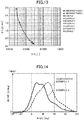
- the total volume Vt is a volume of the operation chamber including the recess of the rotor at 49° BTDC.
- the V/Vt ratio is a ratio of the non-interference volume V of the virtual flame 16 to the volume Vt of the operation chamber. As it were, the V/Vt ratio represents the potential flame growth. The higher the V/Vt ratio, the more easily the flame grows, which will be advantageous in shortening the periods of ignition delay and the combustion. With an increase in the non-interference volume V, it becomes difficult to obtain a compression ratio of 9.7 or more.
- the V/Vt ratio falls thus within a range from 0.014 to 0.026 in one preferred embodiment.
- FIG. 13 is a graph illustrating the relationship between the S/V ratio and the V/Vt ratio.
- Example 6 For each of Comparative Example 1 and Example 6, heat generating characteristics were evaluated at an engine speed of 1500 rpm, a shaft output of 294 kPa, and an EGR ratio of 30%. As shown in FIG. 14 , Example 6 with a lower S/V ratio allows the ignition timing of the L-side spark plug 91 to advance to -49° ATDC (-40° ATDC for the L-side spark plug 91 in Comparative Example 1). The start time of the apparent heat generation was around -24° ATDC. It was confirmed that the combustion time shortened and the combustion center of gravity advanced to improve the thermal efficiency. The ignition timing of the T-side spark plug 92 in each of Comparative Example 1 and Example 6 was at -17° ATDC.
Landscapes
- Engineering & Computer Science (AREA)
- Mechanical Engineering (AREA)
- General Engineering & Computer Science (AREA)
- Chemical & Material Sciences (AREA)
- Combustion & Propulsion (AREA)
- Combustion Methods Of Internal-Combustion Engines (AREA)
- Ignition Installations For Internal Combustion Engines (AREA)
Applications Claiming Priority (1)
| Application Number | Priority Date | Filing Date | Title |
|---|---|---|---|
| JP2018134322A JP7159662B2 (ja) | 2018-07-17 | 2018-07-17 | ロータリピストンエンジン |
Publications (2)
| Publication Number | Publication Date |
|---|---|
| EP3597882A1 true EP3597882A1 (fr) | 2020-01-22 |
| EP3597882B1 EP3597882B1 (fr) | 2021-04-28 |
Family
ID=67105684
Family Applications (1)
| Application Number | Title | Priority Date | Filing Date |
|---|---|---|---|
| EP19179598.8A Active EP3597882B1 (fr) | 2018-07-17 | 2019-06-12 | Moteur à piston rotatif |
Country Status (3)
| Country | Link |
|---|---|
| US (1) | US10982592B2 (fr) |
| EP (1) | EP3597882B1 (fr) |
| JP (1) | JP7159662B2 (fr) |
Families Citing this family (3)
| Publication number | Priority date | Publication date | Assignee | Title |
|---|---|---|---|---|
| US10526961B2 (en) * | 2017-02-09 | 2020-01-07 | Pratt & Whitney Canada Corp. | Rotary internal combustion engine with unequal volumetric ratios |
| US11480143B2 (en) * | 2020-08-10 | 2022-10-25 | Ford Global Technologies, Llc | Methods and systems for a ducted injector |
| JP7391915B2 (ja) * | 2021-06-08 | 2023-12-05 | 章 小倉 | ロータリブレード型エンジン |
Citations (6)
| Publication number | Priority date | Publication date | Assignee | Title |
|---|---|---|---|---|
| US3246636A (en) * | 1965-04-15 | 1966-04-19 | Curtiss Wright Corp | Rotary combustion engine and method of operating same |
| US3696796A (en) * | 1971-02-26 | 1972-10-10 | Curtiss Wright Corp | Fuel combustion in a rotary piston internal combustion engine |
| WO2013017232A2 (fr) * | 2011-08-04 | 2013-02-07 | Avl List Gmbh | Mise en forme de la cuvette du piston d'une machine à piston rotatif |
| JP5672198B2 (ja) * | 2011-08-25 | 2015-02-18 | マツダ株式会社 | 水素ロータリーピストンエンジン |
| JP2015078664A (ja) | 2013-10-18 | 2015-04-23 | マツダ株式会社 | ロータリーピストンエンジン |
| US20170167368A1 (en) * | 2015-02-11 | 2017-06-15 | Uav Engines Ltd. | Rotary Engine Rotor |
Family Cites Families (8)
| Publication number | Priority date | Publication date | Assignee | Title |
|---|---|---|---|---|
| US3606602A (en) * | 1968-11-15 | 1971-09-20 | Yanmar Diesel Engine Co | Combustion chamber of rotary pistion engine |
| FR2273159B1 (fr) * | 1974-05-30 | 1976-10-15 | Dumaine Fernand | |
| IT1040351B (it) * | 1974-08-26 | 1979-12-20 | Audi Ag | Motore a comustione interna a pistone rotante del tipo costruttivo trocoidale |
| US4085712A (en) * | 1977-02-14 | 1978-04-25 | Curtiss-Wright Corporation | Rotary engine with pilot and main fuel nozzles downstream of top center |
| US4083329A (en) * | 1977-02-14 | 1978-04-11 | Curtiss-Wright Corporation | Rotary engine with a pilot fuel nozzle downstream of top center |
| JPS53137316A (en) * | 1977-05-06 | 1978-11-30 | Tadakatsu Ishimi | Rotary engine |
| US5343838A (en) * | 1993-07-29 | 1994-09-06 | Gas Research Institute | Dual radius rotor for pre-mixed-charge rotary engine combustion |
| ES2606170T3 (es) * | 2011-03-10 | 2017-03-23 | Uav Engines Ltd | Rotor de motor rotativo |
-
2018
- 2018-07-17 JP JP2018134322A patent/JP7159662B2/ja active Active
-
2019
- 2019-06-12 EP EP19179598.8A patent/EP3597882B1/fr active Active
- 2019-06-13 US US16/440,372 patent/US10982592B2/en not_active Expired - Fee Related
Patent Citations (6)
| Publication number | Priority date | Publication date | Assignee | Title |
|---|---|---|---|---|
| US3246636A (en) * | 1965-04-15 | 1966-04-19 | Curtiss Wright Corp | Rotary combustion engine and method of operating same |
| US3696796A (en) * | 1971-02-26 | 1972-10-10 | Curtiss Wright Corp | Fuel combustion in a rotary piston internal combustion engine |
| WO2013017232A2 (fr) * | 2011-08-04 | 2013-02-07 | Avl List Gmbh | Mise en forme de la cuvette du piston d'une machine à piston rotatif |
| JP5672198B2 (ja) * | 2011-08-25 | 2015-02-18 | マツダ株式会社 | 水素ロータリーピストンエンジン |
| JP2015078664A (ja) | 2013-10-18 | 2015-04-23 | マツダ株式会社 | ロータリーピストンエンジン |
| US20170167368A1 (en) * | 2015-02-11 | 2017-06-15 | Uav Engines Ltd. | Rotary Engine Rotor |
Also Published As
| Publication number | Publication date |
|---|---|
| EP3597882B1 (fr) | 2021-04-28 |
| JP7159662B2 (ja) | 2022-10-25 |
| JP2020012411A (ja) | 2020-01-23 |
| US20200025063A1 (en) | 2020-01-23 |
| US10982592B2 (en) | 2021-04-20 |
Similar Documents
| Publication | Publication Date | Title |
|---|---|---|
| EP3597882B1 (fr) | Moteur à piston rotatif | |
| CN100485174C (zh) | 内燃机 | |
| US6884050B2 (en) | Roots supercharger with extended length helical rotors | |
| JP7470036B2 (ja) | ディーゼルエンジン | |
| JP7159661B2 (ja) | ロータリピストンエンジン | |
| JP4930479B2 (ja) | ロータリーピストンエンジン及びその設計方法 | |
| JP7305930B2 (ja) | ロータリピストンエンジン | |
| JP7750057B2 (ja) | ロータリーエンジン | |
| JP7415807B2 (ja) | ロータリエンジン | |
| JP7771676B2 (ja) | ロータリーエンジン | |
| JP7771675B2 (ja) | ロータリーエンジン | |
| JP7405006B2 (ja) | ロータリエンジン | |
| JP2005171879A (ja) | 筒内噴射式内燃機関 | |
| US5343838A (en) | Dual radius rotor for pre-mixed-charge rotary engine combustion | |
| CN222457587U (zh) | 气缸盖、发动机、动力总成及车辆 | |
| JP7372903B2 (ja) | ディーゼルエンジン | |
| CN215761916U (zh) | 预燃室总成、发动机和车辆 | |
| JPH0210262Y2 (fr) | ||
| JPH0329548Y2 (fr) | ||
| JPS6055686B2 (ja) | ロ−タリピストンエンジンの燃料噴射装置 | |
| JPH0241316Y2 (fr) | ||
| GB2153428A (en) | Spark ignited i c engine combustion chambers | |
| JPH0422036Y2 (fr) | ||
| JPS6135712Y2 (fr) | ||
| CN115013147A (zh) | 一种促进燃烧室后部燃烧的双转子发动机及其控制策略 |
Legal Events
| Date | Code | Title | Description |
|---|---|---|---|
| PUAI | Public reference made under article 153(3) epc to a published international application that has entered the european phase |
Free format text: ORIGINAL CODE: 0009012 |
|
| STAA | Information on the status of an ep patent application or granted ep patent |
Free format text: STATUS: THE APPLICATION HAS BEEN PUBLISHED |
|
| AK | Designated contracting states |
Kind code of ref document: A1 Designated state(s): AL AT BE BG CH CY CZ DE DK EE ES FI FR GB GR HR HU IE IS IT LI LT LU LV MC MK MT NL NO PL PT RO RS SE SI SK SM TR |
|
| AX | Request for extension of the european patent |
Extension state: BA ME |
|
| STAA | Information on the status of an ep patent application or granted ep patent |
Free format text: STATUS: REQUEST FOR EXAMINATION WAS MADE |
|
| 17P | Request for examination filed |
Effective date: 20200722 |
|
| RBV | Designated contracting states (corrected) |
Designated state(s): AL AT BE BG CH CY CZ DE DK EE ES FI FR GB GR HR HU IE IS IT LI LT LU LV MC MK MT NL NO PL PT RO RS SE SI SK SM TR |
|
| RIC1 | Information provided on ipc code assigned before grant |
Ipc: F02B 55/14 20060101ALN20200908BHEP Ipc: F02B 55/02 20060101AFI20200908BHEP Ipc: F01C 1/22 20060101ALN20200908BHEP Ipc: F02B 53/00 20060101ALN20200908BHEP Ipc: F01C 21/08 20060101ALI20200908BHEP |
|
| RIC1 | Information provided on ipc code assigned before grant |
Ipc: F01C 21/08 20060101ALI20200929BHEP Ipc: F02B 55/02 20060101AFI20200929BHEP Ipc: F01C 1/22 20060101ALN20200929BHEP Ipc: F02B 53/00 20060101ALN20200929BHEP Ipc: F02B 55/14 20060101ALN20200929BHEP |
|
| GRAJ | Information related to disapproval of communication of intention to grant by the applicant or resumption of examination proceedings by the epo deleted |
Free format text: ORIGINAL CODE: EPIDOSDIGR1 |
|
| STAA | Information on the status of an ep patent application or granted ep patent |
Free format text: STATUS: GRANT OF PATENT IS INTENDED |
|
| GRAP | Despatch of communication of intention to grant a patent |
Free format text: ORIGINAL CODE: EPIDOSNIGR1 |
|
| INTG | Intention to grant announced |
Effective date: 20201118 |
|
| GRAS | Grant fee paid |
Free format text: ORIGINAL CODE: EPIDOSNIGR3 |
|
| GRAA | (expected) grant |
Free format text: ORIGINAL CODE: 0009210 |
|
| STAA | Information on the status of an ep patent application or granted ep patent |
Free format text: STATUS: THE PATENT HAS BEEN GRANTED |
|
| AK | Designated contracting states |
Kind code of ref document: B1 Designated state(s): AL AT BE BG CH CY CZ DE DK EE ES FI FR GB GR HR HU IE IS IT LI LT LU LV MC MK MT NL NO PL PT RO RS SE SI SK SM TR |
|
| REG | Reference to a national code |
Ref country code: GB Ref legal event code: FG4D |
|
| REG | Reference to a national code |
Ref country code: CH Ref legal event code: EP |
|
| REG | Reference to a national code |
Ref country code: DE Ref legal event code: R096 Ref document number: 602019004171 Country of ref document: DE |
|
| REG | Reference to a national code |
Ref country code: AT Ref legal event code: REF Ref document number: 1387297 Country of ref document: AT Kind code of ref document: T Effective date: 20210515 |
|
| REG | Reference to a national code |
Ref country code: IE Ref legal event code: FG4D |
|
| PGFP | Annual fee paid to national office [announced via postgrant information from national office to epo] |
Ref country code: DE Payment date: 20210617 Year of fee payment: 3 |
|
| REG | Reference to a national code |
Ref country code: LT Ref legal event code: MG9D |
|
| REG | Reference to a national code |
Ref country code: AT Ref legal event code: MK05 Ref document number: 1387297 Country of ref document: AT Kind code of ref document: T Effective date: 20210428 |
|
| PG25 | Lapsed in a contracting state [announced via postgrant information from national office to epo] |
Ref country code: LT Free format text: LAPSE BECAUSE OF FAILURE TO SUBMIT A TRANSLATION OF THE DESCRIPTION OR TO PAY THE FEE WITHIN THE PRESCRIBED TIME-LIMIT Effective date: 20210428 Ref country code: HR Free format text: LAPSE BECAUSE OF FAILURE TO SUBMIT A TRANSLATION OF THE DESCRIPTION OR TO PAY THE FEE WITHIN THE PRESCRIBED TIME-LIMIT Effective date: 20210428 Ref country code: FI Free format text: LAPSE BECAUSE OF FAILURE TO SUBMIT A TRANSLATION OF THE DESCRIPTION OR TO PAY THE FEE WITHIN THE PRESCRIBED TIME-LIMIT Effective date: 20210428 Ref country code: BG Free format text: LAPSE BECAUSE OF FAILURE TO SUBMIT A TRANSLATION OF THE DESCRIPTION OR TO PAY THE FEE WITHIN THE PRESCRIBED TIME-LIMIT Effective date: 20210728 Ref country code: AT Free format text: LAPSE BECAUSE OF FAILURE TO SUBMIT A TRANSLATION OF THE DESCRIPTION OR TO PAY THE FEE WITHIN THE PRESCRIBED TIME-LIMIT Effective date: 20210428 Ref country code: NL Free format text: LAPSE BECAUSE OF FAILURE TO SUBMIT A TRANSLATION OF THE DESCRIPTION OR TO PAY THE FEE WITHIN THE PRESCRIBED TIME-LIMIT Effective date: 20210428 |
|
| PG25 | Lapsed in a contracting state [announced via postgrant information from national office to epo] |
Ref country code: IS Free format text: LAPSE BECAUSE OF FAILURE TO SUBMIT A TRANSLATION OF THE DESCRIPTION OR TO PAY THE FEE WITHIN THE PRESCRIBED TIME-LIMIT Effective date: 20210828 Ref country code: GR Free format text: LAPSE BECAUSE OF FAILURE TO SUBMIT A TRANSLATION OF THE DESCRIPTION OR TO PAY THE FEE WITHIN THE PRESCRIBED TIME-LIMIT Effective date: 20210729 Ref country code: PL Free format text: LAPSE BECAUSE OF FAILURE TO SUBMIT A TRANSLATION OF THE DESCRIPTION OR TO PAY THE FEE WITHIN THE PRESCRIBED TIME-LIMIT Effective date: 20210428 Ref country code: NO Free format text: LAPSE BECAUSE OF FAILURE TO SUBMIT A TRANSLATION OF THE DESCRIPTION OR TO PAY THE FEE WITHIN THE PRESCRIBED TIME-LIMIT Effective date: 20210728 Ref country code: LV Free format text: LAPSE BECAUSE OF FAILURE TO SUBMIT A TRANSLATION OF THE DESCRIPTION OR TO PAY THE FEE WITHIN THE PRESCRIBED TIME-LIMIT Effective date: 20210428 Ref country code: RS Free format text: LAPSE BECAUSE OF FAILURE TO SUBMIT A TRANSLATION OF THE DESCRIPTION OR TO PAY THE FEE WITHIN THE PRESCRIBED TIME-LIMIT Effective date: 20210428 Ref country code: SE Free format text: LAPSE BECAUSE OF FAILURE TO SUBMIT A TRANSLATION OF THE DESCRIPTION OR TO PAY THE FEE WITHIN THE PRESCRIBED TIME-LIMIT Effective date: 20210428 Ref country code: PT Free format text: LAPSE BECAUSE OF FAILURE TO SUBMIT A TRANSLATION OF THE DESCRIPTION OR TO PAY THE FEE WITHIN THE PRESCRIBED TIME-LIMIT Effective date: 20210830 |
|
| REG | Reference to a national code |
Ref country code: NL Ref legal event code: MP Effective date: 20210428 |
|
| PG25 | Lapsed in a contracting state [announced via postgrant information from national office to epo] |
Ref country code: SK Free format text: LAPSE BECAUSE OF FAILURE TO SUBMIT A TRANSLATION OF THE DESCRIPTION OR TO PAY THE FEE WITHIN THE PRESCRIBED TIME-LIMIT Effective date: 20210428 Ref country code: EE Free format text: LAPSE BECAUSE OF FAILURE TO SUBMIT A TRANSLATION OF THE DESCRIPTION OR TO PAY THE FEE WITHIN THE PRESCRIBED TIME-LIMIT Effective date: 20210428 Ref country code: ES Free format text: LAPSE BECAUSE OF FAILURE TO SUBMIT A TRANSLATION OF THE DESCRIPTION OR TO PAY THE FEE WITHIN THE PRESCRIBED TIME-LIMIT Effective date: 20210428 Ref country code: CZ Free format text: LAPSE BECAUSE OF FAILURE TO SUBMIT A TRANSLATION OF THE DESCRIPTION OR TO PAY THE FEE WITHIN THE PRESCRIBED TIME-LIMIT Effective date: 20210428 Ref country code: DK Free format text: LAPSE BECAUSE OF FAILURE TO SUBMIT A TRANSLATION OF THE DESCRIPTION OR TO PAY THE FEE WITHIN THE PRESCRIBED TIME-LIMIT Effective date: 20210428 Ref country code: SM Free format text: LAPSE BECAUSE OF FAILURE TO SUBMIT A TRANSLATION OF THE DESCRIPTION OR TO PAY THE FEE WITHIN THE PRESCRIBED TIME-LIMIT Effective date: 20210428 Ref country code: MC Free format text: LAPSE BECAUSE OF FAILURE TO SUBMIT A TRANSLATION OF THE DESCRIPTION OR TO PAY THE FEE WITHIN THE PRESCRIBED TIME-LIMIT Effective date: 20210428 Ref country code: RO Free format text: LAPSE BECAUSE OF FAILURE TO SUBMIT A TRANSLATION OF THE DESCRIPTION OR TO PAY THE FEE WITHIN THE PRESCRIBED TIME-LIMIT Effective date: 20210428 |
|
| REG | Reference to a national code |
Ref country code: DE Ref legal event code: R097 Ref document number: 602019004171 Country of ref document: DE |
|
| PLBE | No opposition filed within time limit |
Free format text: ORIGINAL CODE: 0009261 |
|
| STAA | Information on the status of an ep patent application or granted ep patent |
Free format text: STATUS: NO OPPOSITION FILED WITHIN TIME LIMIT |
|
| REG | Reference to a national code |
Ref country code: BE Ref legal event code: MM Effective date: 20210630 |
|
| PG25 | Lapsed in a contracting state [announced via postgrant information from national office to epo] |
Ref country code: LU Free format text: LAPSE BECAUSE OF NON-PAYMENT OF DUE FEES Effective date: 20210612 |
|
| 26N | No opposition filed |
Effective date: 20220131 |
|
| PG25 | Lapsed in a contracting state [announced via postgrant information from national office to epo] |
Ref country code: IE Free format text: LAPSE BECAUSE OF NON-PAYMENT OF DUE FEES Effective date: 20210612 |
|
| PG25 | Lapsed in a contracting state [announced via postgrant information from national office to epo] |
Ref country code: IS Free format text: LAPSE BECAUSE OF FAILURE TO SUBMIT A TRANSLATION OF THE DESCRIPTION OR TO PAY THE FEE WITHIN THE PRESCRIBED TIME-LIMIT Effective date: 20210828 Ref country code: FR Free format text: LAPSE BECAUSE OF NON-PAYMENT OF DUE FEES Effective date: 20210628 Ref country code: AL Free format text: LAPSE BECAUSE OF FAILURE TO SUBMIT A TRANSLATION OF THE DESCRIPTION OR TO PAY THE FEE WITHIN THE PRESCRIBED TIME-LIMIT Effective date: 20210428 |
|
| PG25 | Lapsed in a contracting state [announced via postgrant information from national office to epo] |
Ref country code: IT Free format text: LAPSE BECAUSE OF FAILURE TO SUBMIT A TRANSLATION OF THE DESCRIPTION OR TO PAY THE FEE WITHIN THE PRESCRIBED TIME-LIMIT Effective date: 20210428 Ref country code: BE Free format text: LAPSE BECAUSE OF NON-PAYMENT OF DUE FEES Effective date: 20210630 |
|
| REG | Reference to a national code |
Ref country code: DE Ref legal event code: R119 Ref document number: 602019004171 Country of ref document: DE |
|
| REG | Reference to a national code |
Ref country code: CH Ref legal event code: PL |
|
| PG25 | Lapsed in a contracting state [announced via postgrant information from national office to epo] |
Ref country code: LI Free format text: LAPSE BECAUSE OF NON-PAYMENT OF DUE FEES Effective date: 20220630 Ref country code: CH Free format text: LAPSE BECAUSE OF NON-PAYMENT OF DUE FEES Effective date: 20220630 |
|
| PG25 | Lapsed in a contracting state [announced via postgrant information from national office to epo] |
Ref country code: DE Free format text: LAPSE BECAUSE OF NON-PAYMENT OF DUE FEES Effective date: 20230103 |
|
| PG25 | Lapsed in a contracting state [announced via postgrant information from national office to epo] |
Ref country code: CY Free format text: LAPSE BECAUSE OF FAILURE TO SUBMIT A TRANSLATION OF THE DESCRIPTION OR TO PAY THE FEE WITHIN THE PRESCRIBED TIME-LIMIT Effective date: 20210428 |
|
| PG25 | Lapsed in a contracting state [announced via postgrant information from national office to epo] |
Ref country code: HU Free format text: LAPSE BECAUSE OF FAILURE TO SUBMIT A TRANSLATION OF THE DESCRIPTION OR TO PAY THE FEE WITHIN THE PRESCRIBED TIME-LIMIT; INVALID AB INITIO Effective date: 20190612 |
|
| GBPC | Gb: european patent ceased through non-payment of renewal fee |
Effective date: 20230612 |
|
| PG25 | Lapsed in a contracting state [announced via postgrant information from national office to epo] |
Ref country code: MK Free format text: LAPSE BECAUSE OF FAILURE TO SUBMIT A TRANSLATION OF THE DESCRIPTION OR TO PAY THE FEE WITHIN THE PRESCRIBED TIME-LIMIT Effective date: 20210428 Ref country code: GB Free format text: LAPSE BECAUSE OF NON-PAYMENT OF DUE FEES Effective date: 20230612 |
|
| PG25 | Lapsed in a contracting state [announced via postgrant information from national office to epo] |
Ref country code: TR Free format text: LAPSE BECAUSE OF FAILURE TO SUBMIT A TRANSLATION OF THE DESCRIPTION OR TO PAY THE FEE WITHIN THE PRESCRIBED TIME-LIMIT Effective date: 20210428 |
|
| PG25 | Lapsed in a contracting state [announced via postgrant information from national office to epo] |
Ref country code: MT Free format text: LAPSE BECAUSE OF FAILURE TO SUBMIT A TRANSLATION OF THE DESCRIPTION OR TO PAY THE FEE WITHIN THE PRESCRIBED TIME-LIMIT Effective date: 20210428 |