EP3598471A1 - Kombinierte elektrische vorrichtung mit kontaktor und sicherung - Google Patents
Kombinierte elektrische vorrichtung mit kontaktor und sicherung Download PDFInfo
- Publication number
- EP3598471A1 EP3598471A1 EP18767577.2A EP18767577A EP3598471A1 EP 3598471 A1 EP3598471 A1 EP 3598471A1 EP 18767577 A EP18767577 A EP 18767577A EP 3598471 A1 EP3598471 A1 EP 3598471A1
- Authority
- EP
- European Patent Office
- Prior art keywords
- wire outlet
- contactor
- fuse
- electric apparatus
- combined electric
- Prior art date
- Legal status (The legal status is an assumption and is not a legal conclusion. Google has not performed a legal analysis and makes no representation as to the accuracy of the status listed.)
- Granted
Links
Images

Classifications
-
- H—ELECTRICITY
- H01—ELECTRIC ELEMENTS
- H01H—ELECTRIC SWITCHES; RELAYS; SELECTORS; EMERGENCY PROTECTIVE DEVICES
- H01H85/00—Protective devices in which the current flows through a part of fusible material and this current is interrupted by displacement of the fusible material when this current becomes excessive
- H01H85/02—Details
- H01H85/0241—Structural association of a fuse and another component or apparatus
-
- H—ELECTRICITY
- H01—ELECTRIC ELEMENTS
- H01H—ELECTRIC SWITCHES; RELAYS; SELECTORS; EMERGENCY PROTECTIVE DEVICES
- H01H89/00—Combinations of two or more different basic types of electric switches, relays, selectors and emergency protective devices, not covered by any single one of the other main groups of this subclass
-
- H—ELECTRICITY
- H02—GENERATION; CONVERSION OR DISTRIBUTION OF ELECTRIC POWER
- H02B—BOARDS, SUBSTATIONS OR SWITCHING ARRANGEMENTS FOR THE SUPPLY OR DISTRIBUTION OF ELECTRIC POWER
- H02B1/00—Frameworks, boards, panels, desks, casings; Details of substations or switching arrangements
- H02B1/18—Disposition or arrangement of fuses
-
- H—ELECTRICITY
- H02—GENERATION; CONVERSION OR DISTRIBUTION OF ELECTRIC POWER
- H02B—BOARDS, SUBSTATIONS OR SWITCHING ARRANGEMENTS FOR THE SUPPLY OR DISTRIBUTION OF ELECTRIC POWER
- H02B11/00—Switchgear having carriage withdrawable for isolation
- H02B11/12—Switchgear having carriage withdrawable for isolation with isolation by horizontal withdrawal
-
- H—ELECTRICITY
- H02—GENERATION; CONVERSION OR DISTRIBUTION OF ELECTRIC POWER
- H02B—BOARDS, SUBSTATIONS OR SWITCHING ARRANGEMENTS FOR THE SUPPLY OR DISTRIBUTION OF ELECTRIC POWER
- H02B11/00—Switchgear having carriage withdrawable for isolation
- H02B11/26—Arrangements of fuses, resistors, voltage arresters or the like
-
- H—ELECTRICITY
- H01—ELECTRIC ELEMENTS
- H01H—ELECTRIC SWITCHES; RELAYS; SELECTORS; EMERGENCY PROTECTIVE DEVICES
- H01H31/00—Air-break switches for high tension without arc-extinguishing or arc-preventing means
- H01H31/02—Details
- H01H31/12—Adaptation for built-in fuse
-
- H—ELECTRICITY
- H01—ELECTRIC ELEMENTS
- H01H—ELECTRIC SWITCHES; RELAYS; SELECTORS; EMERGENCY PROTECTIVE DEVICES
- H01H33/00—High-tension or heavy-current switches with arc-extinguishing or arc-preventing means
- H01H33/02—Details
-
- H—ELECTRICITY
- H01—ELECTRIC ELEMENTS
- H01H—ELECTRIC SWITCHES; RELAYS; SELECTORS; EMERGENCY PROTECTIVE DEVICES
- H01H33/00—High-tension or heavy-current switches with arc-extinguishing or arc-preventing means
- H01H33/02—Details
- H01H33/025—Terminal arrangements
Definitions
- the present utility model relates to a combined electric apparatus, in particular to a combined electric apparatus having a contactor and a fuse.
- a plastic insulating cover In an electric power system, in order to ensure that a fuse in a combined electric apparatus is insulated from other components (such as a metal housing, a secondary circuit disposed at an upper end of the metal housing, etc.), it is often necessary for a plastic insulating cover to be additionally designed separately in order to cover the fuse, to achieve an insulating effect. When replacing or servicing the fuse, it is necessary to first remove the plastic insulating cover, causing inconvenience to the operator.
- An object of the present utility model is to provide a combined electric apparatus, having a contactor and a fuse, which guarantees a fuse insulation effect without any increase in the volume of the combined electric apparatus and without the internal arrangement of the combined electric apparatus being affected, and facilitates fuse replacement or servicing.
- the present utility model provides a combined electric apparatus having a contactor and a fuse, comprising a housing and a functional component.
- the housing has a wire outlet side and an operating side opposite the wire outlet side.
- the functional component comprises an upper wire outlet, a lower wire outlet, a contactor and a fuse.
- the upper wire outlet is disposed at the wire outlet side of the housing.
- the lower wire outlet is disposed at the wire outlet side of the housing and located below the upper wire outlet.
- the contactor is placed horizontally inside the housing, and the contactor has a first contact end close to the wire outlet side and a second contact end close to the operating side.
- the first contact end is connected to the lower wire outlet.
- the fuse is disposed in the housing in such a way as to be inclined relative to the contactor, and has a first connection end close to the wire outlet side and a second connection end close to the operating side; the first connection end is connected to the upper wire outlet.
- the first connection end of the fuse is arranged to be remote from the first contact end of the contactor, achieving a safe distance. Furthermore, the second connection end of the fuse is arranged to be remote from a top face of the housing, achieving a safe distance. Air insulation in the safe distance is used to insulate the fuse from other equipment, and a fuse insulation effect is guaranteed without any increase in the volume of the combined electric apparatus and without the internal arrangement of the combined electric apparatus being affected; moreover, the fuse can be replaced or serviced very easily due to the fact that there is no need for an insulating cover to be additionally designed to cover the fuse.
- the combined electric apparatus further comprises an insulating member, which is disposed between the first connection end and the first contact end, in order to increase insulation protection between the fuse and the contactor.
- the second connection end can move in linkage with the second contact end.
- the design described above can make the arrangement of the contactor and the fuse inside the combined electric apparatus more rational.
- the distance between the second connection end and the top face of the housing is greater than 120 mm.
- the distance between the second connection end and the top face of the housing is 130 mm - 140 mm.
- the distance between the first connection end and the contactor is greater than 60 mm.
- the combined electric apparatus comprises three functional components.
- the upper wire outlet, the lower wire outlet, the contactor and the fuse are located in the same vertical plane; the second connection end, relative to the first connection end, is close to the contactor and remote from the top face of the housing.
- Fig. 1 is a structural schematic diagram intended to illustrate a schematic embodiment of a combined electric apparatus having a contactor and a fuse.
- the combined electric apparatus shown in fig. 1 is a single-phase combined electric apparatus having a contactor and a fuse; as shown in the figure, the single-phase combined electric apparatus with the contactor and fuse comprises a housing 12 and a functional component.
- the housing 12 has a wire outlet side 122 and an operating side 124 opposite the wire outlet side 122.
- the wire outlet side 122 is a side at which the combined electric apparatus is connected to a switch cabinet; the operating side 124 is a side at which an operator operates the combined electric apparatus.
- the functional component comprises an upper wire outlet 121, a lower wire outlet 123, a contactor 14 and a fuse 16.
- the upper wire outlet 121 is disposed at the wire outlet side 122 of the housing 12; the lower wire outlet 123 is also disposed at the wire outlet side 122 of the housing 12 and located below the upper wire outlet 121.
- the contactor 14 is placed horizontally inside the housing 12, and the contactor 14 has a first contact end 142 close to the wire outlet side 122 and a second contact end 144 close to the operating side 124; the first contact end 142 is connected to the lower wire outlet 123.
- the fuse is disposed in the housing 12 in such a way as to be inclined relative to the contactor 14; the fuse 16 has a first connection end 162 close to the wire outlet side 122, and a second connection end 164 close to the operating side 124; the first connection end 162 is connected to the upper wire outlet 121.
- inclined means at an angle, not parallel, to a horizontal plane.
- the second connection end 164 With the fuse 16 arranged in an inclined manner as described above, the second connection end 164, relative to the first connection end 162, is close to the contactor 14 and remote from a top face 125 of the housing 12 in a vertical direction.
- the first connection end 162 of the fuse 16 is arranged to be remote from the first contact end 142 of the contactor 14, achieving a safe distance.
- the second connection end 162 of the fuse 16 is arranged to be remote from the top face 125 of the housing, i.e. remote from associated components such as a metal casing and a secondary circuit, achieving a safe distance.
- Air insulation in the safe distance is used to insulate the fuse from other equipment, and a fuse insulation effect is guaranteed without any increase in the volume of the combined electric apparatus and without the internal arrangement of the combined electric apparatus being affected; moreover, the fuse 16 can be replaced or serviced very easily due to the fact that there is no need for an insulating cover to be additionally designed to cover the fuse 16.
- the distance between the second connection end 164 and the top face 125 of the housing 12 is greater than 120 mm, preferably 130 mm - 140 mm.
- the distance between the first connection end 162 and the contactor 14 is greater than 60 mm.
- the combined electric apparatus further comprises an insulating member 18; the insulating member 18 is disposed between the first connection end 162 and the first contact end 142. This increases insulation protection between the fuse 16 and the contactor 14. Any known insulating component may be used for the insulating member.
- the second connection end 164 of the fuse 16 can move in linkage with the second contact end 144 of the contactor 14. For instance, after an overcurrent occurs in the fuse and a blowout occurs, a striking pin thereof will strike outward from the second connection end 164 of the fuse 16; the movement of the striking pin can be transmitted to the second contact end 144 of the contactor mechanically, and the second contact end 144 can transmit a blowout signal to the contactor, causing the contactor 14 to perform an opening operation.
- the design described above can make the arrangement of the contactor and the fuse inside the combined electric apparatus more rational. Of course, depending on the design requirements, a linked-movement position of the fuse 16 and the contactor 14 could also be at another end.
- the combined electric apparatus having a contactor and a fuse shown in fig. 1 has a single-phase structure
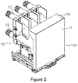
- the design may also be applied in a three-phase structure; as shown in fig. 2 , the combined electric apparatus may comprise three of the functional component described above.
- Three-phase fuses 16 (only one is labelled in the figure) are arranged side by side, and three-phase contactors (not labelled in the figure) are arranged side by side.
- the upper wire outlet 121, the lower wire outlet 123, the contactor 14 and the fuse 16 are located in the same vertical plane; the second connection end 164, relative to the first connection end 162, is close to the contactor 14 and remote from the top face 125 of the housing 12.
Landscapes
- Engineering & Computer Science (AREA)
- Power Engineering (AREA)
- Fuses (AREA)
Applications Claiming Priority (2)
| Application Number | Priority Date | Filing Date | Title |
|---|---|---|---|
| CN201720249042.8U CN206697437U (zh) | 2017-03-14 | 2017-03-14 | 具有接触器和熔断器的组合电器 |
| PCT/CN2018/078981 WO2018166473A1 (zh) | 2017-03-14 | 2018-03-14 | 具有接触器和熔断器的组合电器 |
Publications (3)
| Publication Number | Publication Date |
|---|---|
| EP3598471A1 true EP3598471A1 (de) | 2020-01-22 |
| EP3598471A4 EP3598471A4 (de) | 2020-12-16 |
| EP3598471B1 EP3598471B1 (de) | 2022-01-19 |
Family
ID=60443232
Family Applications (1)
| Application Number | Title | Priority Date | Filing Date |
|---|---|---|---|
| EP18767577.2A Active EP3598471B1 (de) | 2017-03-14 | 2018-03-14 | Kombinierte elektrische vorrichtung mit kontaktor und sicherung |
Country Status (3)
| Country | Link |
|---|---|
| EP (1) | EP3598471B1 (de) |
| CN (1) | CN206697437U (de) |
| WO (1) | WO2018166473A1 (de) |
Families Citing this family (4)
| Publication number | Priority date | Publication date | Assignee | Title |
|---|---|---|---|---|
| CN206697437U (zh) * | 2017-03-14 | 2017-12-01 | 上海西门子开关有限公司 | 具有接触器和熔断器的组合电器 |
| WO2020012599A1 (ja) * | 2018-07-12 | 2020-01-16 | 三菱電機株式会社 | スイッチギヤ |
| CN109823178B (zh) * | 2019-01-08 | 2021-06-04 | 华为技术有限公司 | 一种配电箱及电动汽车 |
| CN114242538B (zh) * | 2021-12-10 | 2024-02-27 | 国网河北省电力有限公司元氏县供电分公司 | 一种高适应性跌落式熔断器 |
Family Cites Families (10)
| Publication number | Priority date | Publication date | Assignee | Title |
|---|---|---|---|---|
| GB1022811A (en) * | 1962-11-07 | 1966-03-16 | Westinghouse Electric Corp | Improvements in or relating to switching apparatus |
| AT381810B (de) * | 1985-05-13 | 1986-12-10 | Sprecher & Schuh Ag | Gekapselte schaltzelle mit sicherung |
| DE8626952U1 (de) * | 1986-10-10 | 1986-12-04 | Siemens AG, 1000 Berlin und 8000 München | Schalterwagen für ein gekapseltes elektrisches Schaltfeld |
| CN2750535Y (zh) * | 2004-10-19 | 2006-01-04 | 厦门兴厦控电气有限公司 | 一种真空接触器-熔断器组合电器 |
| DE102007041958B3 (de) * | 2007-09-03 | 2009-03-12 | Siemens Ag | Einschubbaugruppe für einen Schaltraum |
| JP5152899B2 (ja) * | 2007-11-05 | 2013-02-27 | 株式会社明電舎 | 電力ヒューズの溶断表示装置 |
| CN101162661A (zh) * | 2007-11-26 | 2008-04-16 | 安徽菲迈斯电气有限公司 | 移开式高压交流真空接触器、熔断器组合装置 |
| DE102008017987A1 (de) * | 2008-04-04 | 2009-10-08 | Siemens Aktiengesellschaft | Isolieraufsatz und Isoliergehäuse |
| CN201185314Y (zh) * | 2008-04-18 | 2009-01-21 | 川开电气有限公司 | 一种熔断器-接触器组合电器 |
| CN206697437U (zh) * | 2017-03-14 | 2017-12-01 | 上海西门子开关有限公司 | 具有接触器和熔断器的组合电器 |
-
2017
- 2017-03-14 CN CN201720249042.8U patent/CN206697437U/zh active Active
-
2018
- 2018-03-14 EP EP18767577.2A patent/EP3598471B1/de active Active
- 2018-03-14 WO PCT/CN2018/078981 patent/WO2018166473A1/zh not_active Ceased
Also Published As
| Publication number | Publication date |
|---|---|
| EP3598471B1 (de) | 2022-01-19 |
| WO2018166473A1 (zh) | 2018-09-20 |
| CN206697437U (zh) | 2017-12-01 |
| EP3598471A4 (de) | 2020-12-16 |
Similar Documents
| Publication | Publication Date | Title |
|---|---|---|
| EP3598471A1 (de) | Kombinierte elektrische vorrichtung mit kontaktor und sicherung | |
| CN106441746A (zh) | Gis设备专用气体泄露速度检测装置 | |
| CN106340429A (zh) | 插入式断路器 | |
| CN204012224U (zh) | Gis断路器储能电机防跳保护回路 | |
| CN205160022U (zh) | 新型电缆分支箱 | |
| CN106972397A (zh) | 充气式交流金属封闭开关设备 | |
| CN104297541A (zh) | 一种可变相序的变压联合接线盒 | |
| CN204885044U (zh) | 断路器 | |
| CN202633766U (zh) | 预装箱式变电站变压器室安全网门闭锁装置 | |
| CN104112998B (zh) | 中置柜多功能验电、接地小车的操作方法 | |
| CN204793818U (zh) | 一种gis隔离开关机构误防装置 | |
| CN203746733U (zh) | 改进型gw4-10隔离开关 | |
| CN203503581U (zh) | 小型断路器 | |
| CN103985592A (zh) | 一种带双隔离开关的真空断路器 | |
| CN204464762U (zh) | 一种方便检修的高压开关柜 | |
| CN204270966U (zh) | 一种断路器 | |
| CN204927933U (zh) | 环网真空开关柜体 | |
| CN216213077U (zh) | 跳通连接套件 | |
| CN203910649U (zh) | 一种带双隔离开关的真空断路器 | |
| CN202695275U (zh) | 户外交流高压真空断路器 | |
| CN203312126U (zh) | 一种带过压保护装置的户外高压直动式隔离开关 | |
| CN208209378U (zh) | 一种固定式金属封闭负荷开关柜 | |
| CN202872204U (zh) | 一种操作机构与断路器连体开关柜 | |
| CN102856875A (zh) | 开关柜的断路装置 | |
| CN202601497U (zh) | 一种自动重合器 |
Legal Events
| Date | Code | Title | Description |
|---|---|---|---|
| STAA | Information on the status of an ep patent application or granted ep patent |
Free format text: STATUS: THE INTERNATIONAL PUBLICATION HAS BEEN MADE |
|
| PUAI | Public reference made under article 153(3) epc to a published international application that has entered the european phase |
Free format text: ORIGINAL CODE: 0009012 |
|
| STAA | Information on the status of an ep patent application or granted ep patent |
Free format text: STATUS: REQUEST FOR EXAMINATION WAS MADE |
|
| 17P | Request for examination filed |
Effective date: 20190916 |
|
| AK | Designated contracting states |
Kind code of ref document: A1 Designated state(s): AL AT BE BG CH CY CZ DE DK EE ES FI FR GB GR HR HU IE IS IT LI LT LU LV MC MK MT NL NO PL PT RO RS SE SI SK SM TR |
|
| AX | Request for extension of the european patent |
Extension state: BA ME |
|
| RAP1 | Party data changed (applicant data changed or rights of an application transferred) |
Owner name: SIEMENS AKTIENGESELLSCHAFT |
|
| DAV | Request for validation of the european patent (deleted) | ||
| DAX | Request for extension of the european patent (deleted) | ||
| A4 | Supplementary search report drawn up and despatched |
Effective date: 20201113 |
|
| RIC1 | Information provided on ipc code assigned before grant |
Ipc: H02B 1/18 20060101ALI20201109BHEP Ipc: H01H 85/02 20060101ALI20201109BHEP Ipc: H01H 89/00 20060101AFI20201109BHEP Ipc: H01H 33/02 20060101ALI20201109BHEP Ipc: H02B 1/04 20060101ALI20201109BHEP Ipc: H02B 11/26 20060101ALI20201109BHEP |
|
| GRAP | Despatch of communication of intention to grant a patent |
Free format text: ORIGINAL CODE: EPIDOSNIGR1 |
|
| STAA | Information on the status of an ep patent application or granted ep patent |
Free format text: STATUS: GRANT OF PATENT IS INTENDED |
|
| INTG | Intention to grant announced |
Effective date: 20210924 |
|
| GRAS | Grant fee paid |
Free format text: ORIGINAL CODE: EPIDOSNIGR3 |
|
| GRAA | (expected) grant |
Free format text: ORIGINAL CODE: 0009210 |
|
| STAA | Information on the status of an ep patent application or granted ep patent |
Free format text: STATUS: THE PATENT HAS BEEN GRANTED |
|
| AK | Designated contracting states |
Kind code of ref document: B1 Designated state(s): AL AT BE BG CH CY CZ DE DK EE ES FI FR GB GR HR HU IE IS IT LI LT LU LV MC MK MT NL NO PL PT RO RS SE SI SK SM TR |
|
| REG | Reference to a national code |
Ref country code: GB Ref legal event code: FG4D |
|
| REG | Reference to a national code |
Ref country code: CH Ref legal event code: EP |
|
| REG | Reference to a national code |
Ref country code: DE Ref legal event code: R096 Ref document number: 602018029808 Country of ref document: DE |
|
| REG | Reference to a national code |
Ref country code: AT Ref legal event code: REF Ref document number: 1464281 Country of ref document: AT Kind code of ref document: T Effective date: 20220215 |
|
| REG | Reference to a national code |
Ref country code: IE Ref legal event code: FG4D |
|
| REG | Reference to a national code |
Ref country code: LT Ref legal event code: MG9D |
|
| REG | Reference to a national code |
Ref country code: NL Ref legal event code: MP Effective date: 20220119 |
|
| REG | Reference to a national code |
Ref country code: AT Ref legal event code: MK05 Ref document number: 1464281 Country of ref document: AT Kind code of ref document: T Effective date: 20220119 |
|
| PG25 | Lapsed in a contracting state [announced via postgrant information from national office to epo] |
Ref country code: NL Free format text: LAPSE BECAUSE OF FAILURE TO SUBMIT A TRANSLATION OF THE DESCRIPTION OR TO PAY THE FEE WITHIN THE PRESCRIBED TIME-LIMIT Effective date: 20220119 |
|
| PG25 | Lapsed in a contracting state [announced via postgrant information from national office to epo] |
Ref country code: SE Free format text: LAPSE BECAUSE OF FAILURE TO SUBMIT A TRANSLATION OF THE DESCRIPTION OR TO PAY THE FEE WITHIN THE PRESCRIBED TIME-LIMIT Effective date: 20220119 Ref country code: RS Free format text: LAPSE BECAUSE OF FAILURE TO SUBMIT A TRANSLATION OF THE DESCRIPTION OR TO PAY THE FEE WITHIN THE PRESCRIBED TIME-LIMIT Effective date: 20220119 Ref country code: PT Free format text: LAPSE BECAUSE OF FAILURE TO SUBMIT A TRANSLATION OF THE DESCRIPTION OR TO PAY THE FEE WITHIN THE PRESCRIBED TIME-LIMIT Effective date: 20220519 Ref country code: NO Free format text: LAPSE BECAUSE OF FAILURE TO SUBMIT A TRANSLATION OF THE DESCRIPTION OR TO PAY THE FEE WITHIN THE PRESCRIBED TIME-LIMIT Effective date: 20220419 Ref country code: LT Free format text: LAPSE BECAUSE OF FAILURE TO SUBMIT A TRANSLATION OF THE DESCRIPTION OR TO PAY THE FEE WITHIN THE PRESCRIBED TIME-LIMIT Effective date: 20220119 Ref country code: HR Free format text: LAPSE BECAUSE OF FAILURE TO SUBMIT A TRANSLATION OF THE DESCRIPTION OR TO PAY THE FEE WITHIN THE PRESCRIBED TIME-LIMIT Effective date: 20220119 Ref country code: ES Free format text: LAPSE BECAUSE OF FAILURE TO SUBMIT A TRANSLATION OF THE DESCRIPTION OR TO PAY THE FEE WITHIN THE PRESCRIBED TIME-LIMIT Effective date: 20220119 Ref country code: BG Free format text: LAPSE BECAUSE OF FAILURE TO SUBMIT A TRANSLATION OF THE DESCRIPTION OR TO PAY THE FEE WITHIN THE PRESCRIBED TIME-LIMIT Effective date: 20220419 |
|
| PG25 | Lapsed in a contracting state [announced via postgrant information from national office to epo] |
Ref country code: PL Free format text: LAPSE BECAUSE OF FAILURE TO SUBMIT A TRANSLATION OF THE DESCRIPTION OR TO PAY THE FEE WITHIN THE PRESCRIBED TIME-LIMIT Effective date: 20220119 Ref country code: LV Free format text: LAPSE BECAUSE OF FAILURE TO SUBMIT A TRANSLATION OF THE DESCRIPTION OR TO PAY THE FEE WITHIN THE PRESCRIBED TIME-LIMIT Effective date: 20220119 Ref country code: GR Free format text: LAPSE BECAUSE OF FAILURE TO SUBMIT A TRANSLATION OF THE DESCRIPTION OR TO PAY THE FEE WITHIN THE PRESCRIBED TIME-LIMIT Effective date: 20220420 Ref country code: FI Free format text: LAPSE BECAUSE OF FAILURE TO SUBMIT A TRANSLATION OF THE DESCRIPTION OR TO PAY THE FEE WITHIN THE PRESCRIBED TIME-LIMIT Effective date: 20220119 Ref country code: AT Free format text: LAPSE BECAUSE OF FAILURE TO SUBMIT A TRANSLATION OF THE DESCRIPTION OR TO PAY THE FEE WITHIN THE PRESCRIBED TIME-LIMIT Effective date: 20220119 |
|
| PG25 | Lapsed in a contracting state [announced via postgrant information from national office to epo] |
Ref country code: IS Free format text: LAPSE BECAUSE OF FAILURE TO SUBMIT A TRANSLATION OF THE DESCRIPTION OR TO PAY THE FEE WITHIN THE PRESCRIBED TIME-LIMIT Effective date: 20220519 |
|
| REG | Reference to a national code |
Ref country code: DE Ref legal event code: R097 Ref document number: 602018029808 Country of ref document: DE |
|
| PG25 | Lapsed in a contracting state [announced via postgrant information from national office to epo] |
Ref country code: SM Free format text: LAPSE BECAUSE OF FAILURE TO SUBMIT A TRANSLATION OF THE DESCRIPTION OR TO PAY THE FEE WITHIN THE PRESCRIBED TIME-LIMIT Effective date: 20220119 Ref country code: SK Free format text: LAPSE BECAUSE OF FAILURE TO SUBMIT A TRANSLATION OF THE DESCRIPTION OR TO PAY THE FEE WITHIN THE PRESCRIBED TIME-LIMIT Effective date: 20220119 Ref country code: RO Free format text: LAPSE BECAUSE OF FAILURE TO SUBMIT A TRANSLATION OF THE DESCRIPTION OR TO PAY THE FEE WITHIN THE PRESCRIBED TIME-LIMIT Effective date: 20220119 Ref country code: MC Free format text: LAPSE BECAUSE OF FAILURE TO SUBMIT A TRANSLATION OF THE DESCRIPTION OR TO PAY THE FEE WITHIN THE PRESCRIBED TIME-LIMIT Effective date: 20220119 Ref country code: EE Free format text: LAPSE BECAUSE OF FAILURE TO SUBMIT A TRANSLATION OF THE DESCRIPTION OR TO PAY THE FEE WITHIN THE PRESCRIBED TIME-LIMIT Effective date: 20220119 Ref country code: DK Free format text: LAPSE BECAUSE OF FAILURE TO SUBMIT A TRANSLATION OF THE DESCRIPTION OR TO PAY THE FEE WITHIN THE PRESCRIBED TIME-LIMIT Effective date: 20220119 |
|
| REG | Reference to a national code |
Ref country code: CH Ref legal event code: PL |
|
| PLBE | No opposition filed within time limit |
Free format text: ORIGINAL CODE: 0009261 |
|
| STAA | Information on the status of an ep patent application or granted ep patent |
Free format text: STATUS: NO OPPOSITION FILED WITHIN TIME LIMIT |
|
| PG25 | Lapsed in a contracting state [announced via postgrant information from national office to epo] |
Ref country code: AL Free format text: LAPSE BECAUSE OF FAILURE TO SUBMIT A TRANSLATION OF THE DESCRIPTION OR TO PAY THE FEE WITHIN THE PRESCRIBED TIME-LIMIT Effective date: 20220119 |
|
| REG | Reference to a national code |
Ref country code: BE Ref legal event code: MM Effective date: 20220331 |
|
| 26N | No opposition filed |
Effective date: 20221020 |
|
| GBPC | Gb: european patent ceased through non-payment of renewal fee |
Effective date: 20220419 |
|
| PG25 | Lapsed in a contracting state [announced via postgrant information from national office to epo] |
Ref country code: LU Free format text: LAPSE BECAUSE OF NON-PAYMENT OF DUE FEES Effective date: 20220314 Ref country code: LI Free format text: LAPSE BECAUSE OF NON-PAYMENT OF DUE FEES Effective date: 20220331 Ref country code: IE Free format text: LAPSE BECAUSE OF NON-PAYMENT OF DUE FEES Effective date: 20220314 Ref country code: GB Free format text: LAPSE BECAUSE OF NON-PAYMENT OF DUE FEES Effective date: 20220419 Ref country code: FR Free format text: LAPSE BECAUSE OF NON-PAYMENT OF DUE FEES Effective date: 20220319 Ref country code: CH Free format text: LAPSE BECAUSE OF NON-PAYMENT OF DUE FEES Effective date: 20220331 |
|
| PG25 | Lapsed in a contracting state [announced via postgrant information from national office to epo] |
Ref country code: SI Free format text: LAPSE BECAUSE OF FAILURE TO SUBMIT A TRANSLATION OF THE DESCRIPTION OR TO PAY THE FEE WITHIN THE PRESCRIBED TIME-LIMIT Effective date: 20220119 Ref country code: BE Free format text: LAPSE BECAUSE OF NON-PAYMENT OF DUE FEES Effective date: 20220331 |
|
| PG25 | Lapsed in a contracting state [announced via postgrant information from national office to epo] |
Ref country code: IT Free format text: LAPSE BECAUSE OF FAILURE TO SUBMIT A TRANSLATION OF THE DESCRIPTION OR TO PAY THE FEE WITHIN THE PRESCRIBED TIME-LIMIT Effective date: 20220119 |
|
| PG25 | Lapsed in a contracting state [announced via postgrant information from national office to epo] |
Ref country code: MK Free format text: LAPSE BECAUSE OF FAILURE TO SUBMIT A TRANSLATION OF THE DESCRIPTION OR TO PAY THE FEE WITHIN THE PRESCRIBED TIME-LIMIT Effective date: 20220119 Ref country code: CY Free format text: LAPSE BECAUSE OF FAILURE TO SUBMIT A TRANSLATION OF THE DESCRIPTION OR TO PAY THE FEE WITHIN THE PRESCRIBED TIME-LIMIT Effective date: 20220119 |
|
| PG25 | Lapsed in a contracting state [announced via postgrant information from national office to epo] |
Ref country code: HU Free format text: LAPSE BECAUSE OF FAILURE TO SUBMIT A TRANSLATION OF THE DESCRIPTION OR TO PAY THE FEE WITHIN THE PRESCRIBED TIME-LIMIT; INVALID AB INITIO Effective date: 20180314 |
|
| PG25 | Lapsed in a contracting state [announced via postgrant information from national office to epo] |
Ref country code: MT Free format text: LAPSE BECAUSE OF FAILURE TO SUBMIT A TRANSLATION OF THE DESCRIPTION OR TO PAY THE FEE WITHIN THE PRESCRIBED TIME-LIMIT Effective date: 20220119 |
|
| PGFP | Annual fee paid to national office [announced via postgrant information from national office to epo] |
Ref country code: DE Payment date: 20250520 Year of fee payment: 8 |
|
| PGFP | Annual fee paid to national office [announced via postgrant information from national office to epo] |
Ref country code: TR Payment date: 20260310 Year of fee payment: 9 |
|
| PGFP | Annual fee paid to national office [announced via postgrant information from national office to epo] |
Ref country code: CZ Payment date: 20260310 Year of fee payment: 9 |