EP3598531A1 - Batterie souple ayant une structure de couplage de languette de renfort et structure de couplage de flexion de fils d'électrode - Google Patents
Batterie souple ayant une structure de couplage de languette de renfort et structure de couplage de flexion de fils d'électrode Download PDFInfo
- Publication number
- EP3598531A1 EP3598531A1 EP17900776.0A EP17900776A EP3598531A1 EP 3598531 A1 EP3598531 A1 EP 3598531A1 EP 17900776 A EP17900776 A EP 17900776A EP 3598531 A1 EP3598531 A1 EP 3598531A1
- Authority
- EP
- European Patent Office
- Prior art keywords
- electrode
- tab
- electrode lead
- connection tab
- assembly
- Prior art date
- Legal status (The legal status is an assumption and is not a legal conclusion. Google has not performed a legal analysis and makes no representation as to the accuracy of the status listed.)
- Pending
Links
- 238000005452 bending Methods 0.000 title claims description 25
- 230000008878 coupling Effects 0.000 title 2
- 238000010168 coupling process Methods 0.000 title 2
- 238000005859 coupling reaction Methods 0.000 title 2
- 230000002787 reinforcement Effects 0.000 title 1
- 238000005728 strengthening Methods 0.000 claims abstract description 48
- 239000000203 mixture Substances 0.000 claims abstract description 10
- 239000002390 adhesive tape Substances 0.000 claims 1
- 229910052751 metal Inorganic materials 0.000 description 11
- 239000002184 metal Substances 0.000 description 11
- PXHVJJICTQNCMI-UHFFFAOYSA-N Nickel Chemical compound [Ni] PXHVJJICTQNCMI-UHFFFAOYSA-N 0.000 description 8
- 239000003792 electrolyte Substances 0.000 description 7
- 239000011888 foil Substances 0.000 description 6
- 238000000034 method Methods 0.000 description 6
- 238000007789 sealing Methods 0.000 description 6
- RYGMFSIKBFXOCR-UHFFFAOYSA-N Copper Chemical compound [Cu] RYGMFSIKBFXOCR-UHFFFAOYSA-N 0.000 description 4
- 229910052782 aluminium Inorganic materials 0.000 description 4
- XAGFODPZIPBFFR-UHFFFAOYSA-N aluminium Chemical compound [Al] XAGFODPZIPBFFR-UHFFFAOYSA-N 0.000 description 4
- 229910052802 copper Inorganic materials 0.000 description 4
- 239000010949 copper Substances 0.000 description 4
- 229910052759 nickel Inorganic materials 0.000 description 4
- 239000011347 resin Substances 0.000 description 4
- 229920005989 resin Polymers 0.000 description 4
- WHXSMMKQMYFTQS-UHFFFAOYSA-N Lithium Chemical compound [Li] WHXSMMKQMYFTQS-UHFFFAOYSA-N 0.000 description 3
- 238000005304 joining Methods 0.000 description 3
- 229910052744 lithium Inorganic materials 0.000 description 3
- 239000000463 material Substances 0.000 description 3
- 238000003466 welding Methods 0.000 description 3
- 230000007423 decrease Effects 0.000 description 2
- 230000009257 reactivity Effects 0.000 description 2
- 229910001220 stainless steel Inorganic materials 0.000 description 2
- 239000010935 stainless steel Substances 0.000 description 2
- 239000000853 adhesive Substances 0.000 description 1
- 230000001070 adhesive effect Effects 0.000 description 1
- OJIJEKBXJYRIBZ-UHFFFAOYSA-N cadmium nickel Chemical compound [Ni].[Cd] OJIJEKBXJYRIBZ-UHFFFAOYSA-N 0.000 description 1
- 230000015556 catabolic process Effects 0.000 description 1
- 230000001413 cellular effect Effects 0.000 description 1
- 230000007797 corrosion Effects 0.000 description 1
- 238000005260 corrosion Methods 0.000 description 1
- 238000006731 degradation reaction Methods 0.000 description 1
- 230000000694 effects Effects 0.000 description 1
- 238000003487 electrochemical reaction Methods 0.000 description 1
- 238000005516 engineering process Methods 0.000 description 1
- 229910052739 hydrogen Inorganic materials 0.000 description 1
- 239000001257 hydrogen Substances 0.000 description 1
- 230000037427 ion transport Effects 0.000 description 1
- 150000002500 ions Chemical class 0.000 description 1
- 230000014759 maintenance of location Effects 0.000 description 1
- 239000007769 metal material Substances 0.000 description 1
- 230000003647 oxidation Effects 0.000 description 1
- 238000007254 oxidation reaction Methods 0.000 description 1
- 238000012856 packing Methods 0.000 description 1
- 238000003825 pressing Methods 0.000 description 1
- 239000006163 transport media Substances 0.000 description 1
- 230000037303 wrinkles Effects 0.000 description 1
Images








Classifications
-
- H—ELECTRICITY
- H01—ELECTRIC ELEMENTS
- H01M—PROCESSES OR MEANS, e.g. BATTERIES, FOR THE DIRECT CONVERSION OF CHEMICAL ENERGY INTO ELECTRICAL ENERGY
- H01M10/00—Secondary cells; Manufacture thereof
- H01M10/04—Construction or manufacture in general
- H01M10/0436—Small-sized flat cells or batteries for portable equipment
-
- H—ELECTRICITY
- H01—ELECTRIC ELEMENTS
- H01M—PROCESSES OR MEANS, e.g. BATTERIES, FOR THE DIRECT CONVERSION OF CHEMICAL ENERGY INTO ELECTRICAL ENERGY
- H01M50/00—Constructional details or processes of manufacture of the non-active parts of electrochemical cells other than fuel cells, e.g. hybrid cells
- H01M50/50—Current conducting connections for cells or batteries
- H01M50/531—Electrode connections inside a battery casing
- H01M50/54—Connection of several leads or tabs of plate-like electrode stacks, e.g. electrode pole straps or bridges
-
- H—ELECTRICITY
- H01—ELECTRIC ELEMENTS
- H01M—PROCESSES OR MEANS, e.g. BATTERIES, FOR THE DIRECT CONVERSION OF CHEMICAL ENERGY INTO ELECTRICAL ENERGY
- H01M2220/00—Batteries for particular applications
- H01M2220/30—Batteries in portable systems, e.g. mobile phone, laptop
-
- H—ELECTRICITY
- H01—ELECTRIC ELEMENTS
- H01M—PROCESSES OR MEANS, e.g. BATTERIES, FOR THE DIRECT CONVERSION OF CHEMICAL ENERGY INTO ELECTRICAL ENERGY
- H01M50/00—Constructional details or processes of manufacture of the non-active parts of electrochemical cells other than fuel cells, e.g. hybrid cells
- H01M50/10—Primary casings; Jackets or wrappings
- H01M50/102—Primary casings; Jackets or wrappings characterised by their shape or physical structure
- H01M50/103—Primary casings; Jackets or wrappings characterised by their shape or physical structure prismatic or rectangular
-
- H—ELECTRICITY
- H01—ELECTRIC ELEMENTS
- H01M—PROCESSES OR MEANS, e.g. BATTERIES, FOR THE DIRECT CONVERSION OF CHEMICAL ENERGY INTO ELECTRICAL ENERGY
- H01M50/00—Constructional details or processes of manufacture of the non-active parts of electrochemical cells other than fuel cells, e.g. hybrid cells
- H01M50/50—Current conducting connections for cells or batteries
- H01M50/531—Electrode connections inside a battery casing
- H01M50/536—Electrode connections inside a battery casing characterised by the method of fixing the leads to the electrodes, e.g. by welding
-
- H—ELECTRICITY
- H01—ELECTRIC ELEMENTS
- H01M—PROCESSES OR MEANS, e.g. BATTERIES, FOR THE DIRECT CONVERSION OF CHEMICAL ENERGY INTO ELECTRICAL ENERGY
- H01M50/00—Constructional details or processes of manufacture of the non-active parts of electrochemical cells other than fuel cells, e.g. hybrid cells
- H01M50/50—Current conducting connections for cells or batteries
- H01M50/543—Terminals
- H01M50/547—Terminals characterised by the disposition of the terminals on the cells
- H01M50/548—Terminals characterised by the disposition of the terminals on the cells on opposite sides of the cell
-
- H—ELECTRICITY
- H01—ELECTRIC ELEMENTS
- H01M—PROCESSES OR MEANS, e.g. BATTERIES, FOR THE DIRECT CONVERSION OF CHEMICAL ENERGY INTO ELECTRICAL ENERGY
- H01M50/00—Constructional details or processes of manufacture of the non-active parts of electrochemical cells other than fuel cells, e.g. hybrid cells
- H01M50/50—Current conducting connections for cells or batteries
- H01M50/543—Terminals
- H01M50/547—Terminals characterised by the disposition of the terminals on the cells
- H01M50/55—Terminals characterised by the disposition of the terminals on the cells on the same side of the cell
-
- H—ELECTRICITY
- H01—ELECTRIC ELEMENTS
- H01M—PROCESSES OR MEANS, e.g. BATTERIES, FOR THE DIRECT CONVERSION OF CHEMICAL ENERGY INTO ELECTRICAL ENERGY
- H01M50/00—Constructional details or processes of manufacture of the non-active parts of electrochemical cells other than fuel cells, e.g. hybrid cells
- H01M50/50—Current conducting connections for cells or batteries
- H01M50/543—Terminals
- H01M50/552—Terminals characterised by their shape
- H01M50/553—Terminals adapted for prismatic, pouch or rectangular cells
-
- H—ELECTRICITY
- H01—ELECTRIC ELEMENTS
- H01M—PROCESSES OR MEANS, e.g. BATTERIES, FOR THE DIRECT CONVERSION OF CHEMICAL ENERGY INTO ELECTRICAL ENERGY
- H01M50/00—Constructional details or processes of manufacture of the non-active parts of electrochemical cells other than fuel cells, e.g. hybrid cells
- H01M50/50—Current conducting connections for cells or batteries
- H01M50/543—Terminals
- H01M50/552—Terminals characterised by their shape
- H01M50/553—Terminals adapted for prismatic, pouch or rectangular cells
- H01M50/557—Plate-shaped terminals
-
- Y—GENERAL TAGGING OF NEW TECHNOLOGICAL DEVELOPMENTS; GENERAL TAGGING OF CROSS-SECTIONAL TECHNOLOGIES SPANNING OVER SEVERAL SECTIONS OF THE IPC; TECHNICAL SUBJECTS COVERED BY FORMER USPC CROSS-REFERENCE ART COLLECTIONS [XRACs] AND DIGESTS
- Y02—TECHNOLOGIES OR APPLICATIONS FOR MITIGATION OR ADAPTATION AGAINST CLIMATE CHANGE
- Y02E—REDUCTION OF GREENHOUSE GAS [GHG] EMISSIONS, RELATED TO ENERGY GENERATION, TRANSMISSION OR DISTRIBUTION
- Y02E60/00—Enabling technologies; Technologies with a potential or indirect contribution to GHG emissions mitigation
- Y02E60/10—Energy storage using batteries
-
- Y—GENERAL TAGGING OF NEW TECHNOLOGICAL DEVELOPMENTS; GENERAL TAGGING OF CROSS-SECTIONAL TECHNOLOGIES SPANNING OVER SEVERAL SECTIONS OF THE IPC; TECHNICAL SUBJECTS COVERED BY FORMER USPC CROSS-REFERENCE ART COLLECTIONS [XRACs] AND DIGESTS
- Y02—TECHNOLOGIES OR APPLICATIONS FOR MITIGATION OR ADAPTATION AGAINST CLIMATE CHANGE
- Y02P—CLIMATE CHANGE MITIGATION TECHNOLOGIES IN THE PRODUCTION OR PROCESSING OF GOODS
- Y02P70/00—Climate change mitigation technologies in the production process for final industrial or consumer products
- Y02P70/50—Manufacturing or production processes characterised by the final manufactured product
Definitions
- the present disclosure relates to a flexible battery having a joint strengthening structure between an electrode tab and an electrode lead in which a strengthening tab formed as a metal plate having a predetermined thickness is placed between the electrode lead and an electrode lead connection tab included in an electrode assembly when the electrode tab and the electrode lead are assembled and an end of the electrode lead can be bent in the 180° opposite direction while it is welded on the electrode lead connection tab, and, thus, electrochemical properties can be maintained even when a secondary battery is bent toward the outside of the electrode assembly.
- a secondary battery refers to a battery, which can be charged and discharged, as opposed to a primary battery which cannot be charged, and has been widely used in the field of advanced electronic devices such as cellular phones, notebook computers, camcorders, and the like.
- the form factor of such electronic devices is becoming lighter, if not smaller, all the while performance is improving.
- Add to those advancements in the development and implementation of the Internet of Things (loT), and secondary batteries as power supplies take on greater importance.
- lithium secondary batteries have a higher voltage than nickel-cadmium batteries or nickel-hydrogen batteries, which are mainly used as power supplies for portable electronic devices and also have a high energy density per unit weight. Therefore, demand for lithium secondary batteries is increasing.
- a secondary battery typically utilizes an electrochemical reaction occurring between an electrolyte and a positive electrode and a negative electrode when the positive electrode and the negative electrode are connected to each other when inserted into the electrolyte.
- a secondary battery can be recharged by a charger and used again when energy is consumed by an electronic device. Therefore, the use of secondary batteries has increased with the popularization of wireless electronic devices.
- a lithium secondary battery typically includes a jelly-roll type electrode assembly in which a separator is inserted between a positive electrode plate and a negative electrode plate and is then spirally wound together; or includes a flexible stacked type electrode assembly in which multiple positive electrode plates and negative electrode plates are stacked with a separator interposed therebetween.
- a cylindrical battery may be manufactured by housing the jelly-roll type electrode assembly in a cylindrical can, injecting an electrolyte therein, and sealing the can; and a prismatic battery may be manufactured by pressing the jelly-roll type electrode assembly or the stacked type electrode assembly to be flat and then housing the flat electrode assembly in a prismatic can.
- a pouch type battery may be manufactured by packing the jelly-roll type electrode assembly or the stacked type electrode assembly together with an electrolyte in a pouch type case.
- a positive electrode tab and a negative electrode tab may be withdrawn from a positive electrode plate and a negative electrode plate, respectively, to the outside of the electrode assembly and then connected to a positive electrode and a negative electrode of a secondary battery.
- an electrode tab on multiple positive electrode plates and negative electrode plates stacked in a vertical direction may be connected to an electrode lead.
- a conventional joint structure between an electrode tab and an electrode lead slightly decreases in coherence during direct welding. Thus, when a battery is bent or the like during use, a problem occurs in the joint between the electrode tab and the electrode lead.
- a pouch type battery will be explained with reference to Korean Patent Laid-open Publication No. 10-2013-0063709 which discloses a pouch type secondary battery in which two electrodes, a separator, and an electrolyte are placed in a pouch and sealed and the pouch includes an inner resin layer, a metal foil layer, and an outer resin layer and a buffer layer having less reactivity than the metal foil layer is formed between the inner resin layer and the metal foil layer.
- the buffer layer having less reactivity than the metal foil layer is added, and, thus, even when the inner resin layer is damaged such as micro cracks, the buffer layer can suppress oxidation of the metal foil layer. Therefore, it is possible to suppress corrosion on the outside of the battery.
- metal foil is basically vulnerable to deformation such as wrinkles during bending and thus may cause degradation in the properties of a flexible battery.
- Patent Document 1 KR10-2013-0063709 A
- a stable flexible battery that has a strengthening tab formed as a metal plate of a predetermined thickness placed between an electrode lead and an electrode lead connection tab that is included in an electrode assembly.
- An end of the electrode lead may be bent 180° in a direction opposite toward the outside of the electrode assembly while it is welded on the electrode lead connection tab, thus electrochemical properties may be maintained by minimizing a local mechanical load caused by bending of the flexible battery.
- a flexible battery assembly may include: at least: an electrode assembly that may be equipped with one or more unit cells, each including a pair of electrode plates having different polarities with a separator interposed therebetween, and electrode tabs protruding from the respective electrode plates but not coated with an electrode mixture; a strengthening tab welded and fixed on any one electrode lead connection tab among the electrode tabs included in the electrode assembly; and a pair of electrode leads welded on the strengthening tab and the other electrode lead connection tab, respectively. Any one of the pair of electrode leads may be welded on the strengthening tab, which is added between the electrode lead connection tab and the electrode lead, and then connected to the electrode lead connection tab. The other one of the pair of electrode leads may be bent 180° in a direction opposite toward the outside of the electrode assembly while it is welded on the electrode lead connection tab toward the electrode assembly.
- a tab-tab joint portion may include electrode plates having the same polarity electrically connected in parallel to each other through an electrode parallel connection tab, and the tab-tab joint portion may be taped on a separator that covers an outer surface of the outermost electrode plate placed on the uppermost or lowermost end of the electrode assembly.
- the flexible battery may further includes a case that has upper stamping sections and lower stamping sections repeatedly stamped to surround the outside of the electrode assembly.
- the multiple upper stamping sections and lower stamping sections are successively formed in a direction parallel to the width of the electrode assembly and the case.
- a tab-lead joint portion that is backed and strengthened using the strengthening tab and is located between the electrode lead connection tab and the electrode lead may be inserted into the electrode assembly, and a tab-lead joint portion that includes an electrode lead bending joint structure may be inserted in the electrode assembly.
- the electrode plates included in the electrode assembly may include a first electrode plate E1 that includes the electrode lead connection tab and the electrode parallel connection tab on both sides and a second electrode plate E2 that includes only the electrode parallel connection tab on one side, and an electrode mixture may be coated on the second electrode plate E2 to cover the electrode lead connection tab of the first electrode plate E1.
- a stable flexible battery having a structure in which a strengthening tab that is formed as a metal plate of a predetermined thickness may be placed between an electrode lead and an electrode lead connection tab that is included in an electrode assembly, and an end of the electrode lead may be bent 180° in a direction opposite toward the outside of the electrode assembly while it is welded on the electrode lead connection tab.
- electrochemical properties may be maintained by minimizing a local mechanical load caused by bending of the flexible battery.
- first, second, A, B, (a), (b), etc. can be used. These terms are used only to differentiate the components from other components. Therefore, the nature, order, sequence, etc., of the corresponding components are not limited by these terms. It is to be understood that when one element is referred to as being “connected to” or “coupled to” another element, it may be directly connected or coupled to another element or be connected or coupled to another element, having still another element “connected” or “coupled” therebetween.
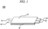
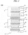
- FIG. 1 and FIG. 2 an embodiment of an electrode assembly included in a flexible battery according to the present disclosure will be described.
- An electrode assembly 100 includes unit cells, each including a negative electrode plate 10 and a positive electrode plate 20 with a separator 30 interposed therebetween, an electrolyte serving as an ion transport medium between negative electrode plate 10 and positive electrode plate 20, and electrode tabs protruding from the electrode plates may be used to implement electrode parallel connection and as an electrode lead connection, depending on the application. Any one or more of the electrode plates including the negative electrode plate 10 and the positive electrode plate 20 may be equipped on both sides with an electrode parallel connection tab and an electrode lead connection tab spaced apart from each other.
- a negative electrode plate 10 placed on the lowermost end of the electrode assembly 100 may be equipped with a negative electrode parallel connection tab 12 and a negative electrode lead connection tab 14, and a positive electrode plate 20 placed on the opposite side of the separator facing the negative electrode 10 may be equipped with a positive electrode parallel connection tab 22 and a positive electrode lead connection tab 24.
- each electrode plate serving as a current collector may be coated with an electrode mixture, and the electrode parallel connection tabs and the electrode lead connection tabs protrude from the electrode plates.
- the electrode parallel connection tabs and the electrode lead connection tabs may be exposed without being coated with the electrode mixture.
- the multiple electrode plates having the same polarity may be connected to each other through an electrode parallel connection tab. That is, multiple negative electrode plates 10 and multiple positive electrode plates 20 are electrically connected in parallel to each other forming a tab-tab joint portion connecting electrode tabs.
- the electrode assembly may be electrically connected through the electrode lead connection tab to an electrode lead exposed to the outside of a case.
- the separator physically separates the electrode plates, but allows ions contained in the electrolyte to pass through.
- each negative electrode plate placed on the uppermost end and the lowermost end of the electrode assembly, only one surface of each negative electrode plate may be coated with a negative electrode mixture.
- Tab-tab joint portions connected in parallel to each other are located on the separator covering an outer surface of the outermost electrode plate placed on the uppermost end or the lowermost end of the electrode assembly and then finished and taped.
- a tab-tab joint portion where the electrode parallel connection tabs 12 and 22 on the electrode plate are connected in parallel to each other and a tab-lead joint portion where the electrode lead connection tabs 14 and 24 and the electrode lead are connected to each other are electrically connected and joined to each other by any one of connection methods including spot welding, laser welding, and joining with a conductive adhesive.
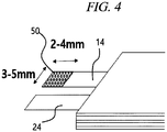
- a separate strengthening tab 50 added to electrode lead connection tabs 14 and 24 that are placed on one side of the electrode assembly. Then, the strengthening tab 50 is joined to an electrode lead 60.
- a backing structure for the electrode lead connection tabs 14 and 24 and the electrode lead 60 may be formed using the strengthening tab 50.
- the strengthened joint method for the electrode lead connection tabs 14 and 24 and the electrode lead 60 may be applied to at least any one of a positive electrode tab and a negative electrode tab.
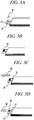
- FIG. 3A shows that, among multiple electrode plates included in an electrode assembly, an electrode equipped with an electrode lead connection tab may protrude to one side of the electrode assembly to be joined to strengthening tab 50, which may be formed of a metal material.
- FIG. 3B shows that strengthening tab 50 may be joined on the electrode lead connection tab.
- FIG. 3C shows that the electrode lead may be prepared to be joined on the electrode lead connection tab on which the strengthening tab 50 is added.
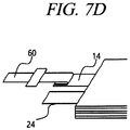
- FIG. 3D shows that the electrode may be joined on the electrode lead connection tab on which the strengthening tab 50 is added.
- the strengthening tab 50 added on the electrode lead connection tab reinforces the strength of a joint portion between the electrode lead connection tab and the electrode lead 60 and thus physically strengthens the joint portion.
- the strengthening tab 50 formed of a homogeneous or heterogeneous metal and having a thickness one to three times greater than the electrode lead connection tab is added by backing and welded.
- the strengthening tab 50 added by backing and the electrode lead connection tab may have the same thickness or different width.
- the added strengthening tab 50 may have a width of 3 mm to 5 mm and a length of 2 mm to 4 mm. However, this is just an example and the present disclosure is not limited thereto.
- the electrode lead assembled on the strengthening tab 50 added by backing and joined to the electrode lead connection tab may have a width of, e.g., 2 mm to 3 mm and a length of, e.g., 0.5 mm to 1 mm.
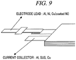
- the current collector of the electrode plate in the present disclosure may be any one of a group consisting of aluminum, stainless steel and copper, and the electrode lead may be formed of any one material of a group consisting of aluminum, nickel, and nickel-coated copper.
- the strengthening tab 50 added by backing on the tab-lead joint portion for the electrode lead connection tab and the electrode lead may be formed into any one shape of a group consisting of a circular shape, an oval shape, and a polygonal shape.
- electrode lead 60 may be joined to electrode lead connection tabs 14 and 24 on one side of the electrode assembly.
- electrode lead 60 may be placed in parallel above the electrode lead connection tabs 14 and 24, a part of an end of the electrode lead 60 may be welded on upper ends of the electrode lead connection tabs 14 and 24. In this state, the electrode lead 60 may be bent 180°, thus electrode lead 60 may be bent from the electrode lead connection tabs 14 and 24 toward the outside of the electrode assembly.
- This method of connecting the electrode lead connection tabs 14 and 24 and the electrode lead 60 by bending may be applied to at least any one of a positive electrode tab and a negative electrode tab.
- a joint portion of the electrode lead 60 that may be joined to the upper end of the electrode lead connection tab extended from the electrode plate of the electrode assembly may have a width of, e.g., 2 mm to 3 mm and a length of, e.g., 1 mm to 3 mm.
- the joint portion may have an optimal length of 1.5 mm.
- this is just an example and the present disclosure is not limited thereto.
- the current collector of the electrode plate may be any one of a group consisting of aluminum, stainless steel and copper
- the electrode lead may be formed of any one material of a group consisting of aluminum, nickel, or nickel-coated copper.
- a case 200 having a structure in which upper stamping sections and lower stamping sections are repeatedly stamped is placed to surround the outside of the electrode assembly according to the present disclosure.
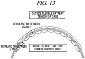
- the multiple upper stamping sections and lower stamping sections repeatedly stamped on the case have a repeated pattern and shape and thus can compress and tension the flexible battery including the electrode assembly during bending, twisting, or crumpling.
- the multiple upper stamping sections and lower stamping sections may be successively formed in a direction parallel to the width of the electrode assembly and the case.
- the multiple upper stamping sections and lower stamping sections may be stamped by an upper mold and a lower mold, respectively.
- the case surrounding the outside of the electrode assembly may include an upper case 210 and a lower case 220 on the electrode assembly based on a dotted line in a sealing portion 230. That is, multiple upper stamping sections 212 and 222 and multiple lower stamping sections 214 and 224 repeatedly formed on the case are symmetric with respect to the sealing portion and symmetrically stamped on the upper case 210 and the lower case 220. In this state, the sealing portion is bent in a vertically symmetric manner and then, the electrode assembly may be housed inside the case.
- the sealing portion which may divide the upper case 210 and the lower case 220, may have a width of, e.g., 3 mm to 5 mm, and a substantive sealing may have a width of, e.g., 1 mm to 2 mm.
- a width of, e.g., 1 mm to 2 mm may be a width of, e.g., 1 mm to 2 mm.
- the heights h and h' of the multiple upper stamping sections and lower stamping sections repeated on the case may be in the range of, e.g., 0.5 mm to 1 mm and have an optimum value of 0.75 mm. However, this is just an example and the present disclosure is not limited thereto.
- the height h of the repeated upper stamping sections increases to between h to 2h due to the compressive stress caused by bending, twisting, or crumpling. Outside the flexible battery, the height h of the repeated upper stamping sections decreases to between 0 and h due to the tensile stress.
- a first tab-lead joint portion has a structure in which backing and strengthening is implemented by a strengthening tab added between an electrode lead connection tab and an electrode lead
- a second tab-lead joint portion has a structure in which while a part of an end of the electrode lead is welded on the upper ends of the electrode lead connection tabs 14 and 24, the electrode lead is bent in the 180° opposite direction toward the outside of the electrode assembly.
- FIG. 14 illustrates that the tab-lead joint portion including a backing and strengthening joint structure and an electrode lead bending joint structure is inserted into the electrode assembly and then aligned by a tab-tab joint portion.
- FIG. 15 shows a comparison between a battery that includes an electrode assembly in which a tab-lead joint portion is inserted and electrodes are aligned at the same time, in accordance with at least one embodiment disclosed herein, and a battery that does not include the electrode assembly.
- the tab-lead joint portion which may include the backing and strengthening joint structure using the strengthening tab 50 and the electrode lead bending joint structure, is inserted into the electrode assembly, there is no breakage on the joint portion between the electrode lead connection tab and the electrode lead during a bending test on the flexible battery.
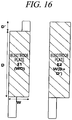
- FIG. 17 illustrates an example embodiment of an electrode plate included in an electrode assembly to insert the tab-lead joint portion including the backing and strengthening joint structure using the strengthening tab 50 and the electrode lead bending structure into the electrode assembly, as disclosed herein.
- the electrode plates included in the electrode assembly include a first electrode plate E1 including all the electrode lead connection tab and the electrode parallel connection tab on both sides and a second electrode plate E2 including only the electrode parallel connection tab on one side.
- a portion coated with the electrode mixture has a horizontal length of W and a vertical length of D and thus has an area of WD.
- the electrode lead connection tab has a vertical length of D'.
- a portion coated with the electrode mixture has a horizontal length of W and a vertical length of D+D' and thus has an area of W(D+D').
- the tab-lead joint portion can be inserted into the electrode assembly and aligned at the same time when the cell can be driven stably.
- a bending test was performed on the flexible battery according to the present disclosure with a cylindrical structure of an R20 battery to test bending properties. To be specific, the test was repeated 5000 times, and the flexible battery was confirmed as having a capacity retention of 90% or more.
- the present disclosure makes it possible to implement a stable flexible battery in which a strengthening tab formed as a metal plate having a predetermined thickness is placed between an electrode lead and an electrode lead connection tab included in an electrode assembly when the electrode lead and the electrode lead connection tab are assembled and an electrode lead bending joint structure is combined, and, thus, electrochemical properties can be maintained by minimizing local mechanical load caused by bending of the flexible battery.
Landscapes
- Chemical & Material Sciences (AREA)
- Chemical Kinetics & Catalysis (AREA)
- Electrochemistry (AREA)
- General Chemical & Material Sciences (AREA)
- Engineering & Computer Science (AREA)
- Manufacturing & Machinery (AREA)
- Connection Of Batteries Or Terminals (AREA)
- Secondary Cells (AREA)
Applications Claiming Priority (2)
| Application Number | Priority Date | Filing Date | Title |
|---|---|---|---|
| KR1020170033539A KR101783703B1 (ko) | 2017-03-17 | 2017-03-17 | 보강 탭 결합 구조 및 전극 리드 굽힘 결합 구조를 갖는 플렉서블 전지 |
| PCT/KR2017/011815 WO2018169157A1 (fr) | 2017-03-17 | 2017-10-25 | Batterie souple ayant une structure de couplage de languette de renfort et structure de couplage de flexion de fils d'électrode |
Publications (2)
| Publication Number | Publication Date |
|---|---|
| EP3598531A1 true EP3598531A1 (fr) | 2020-01-22 |
| EP3598531A4 EP3598531A4 (fr) | 2021-01-20 |
Family
ID=60138967
Family Applications (1)
| Application Number | Title | Priority Date | Filing Date |
|---|---|---|---|
| EP17900776.0A Pending EP3598531A4 (fr) | 2017-03-17 | 2017-10-25 | Batterie souple ayant une structure de couplage de languette de renfort et structure de couplage de flexion de fils d'électrode |
Country Status (6)
| Country | Link |
|---|---|
| US (2) | US11335980B2 (fr) |
| EP (1) | EP3598531A4 (fr) |
| JP (2) | JP6899536B2 (fr) |
| KR (1) | KR101783703B1 (fr) |
| CN (1) | CN110462881B (fr) |
| WO (1) | WO2018169157A1 (fr) |
Cited By (3)
| Publication number | Priority date | Publication date | Assignee | Title |
|---|---|---|---|---|
| EP3716384A4 (fr) * | 2017-11-24 | 2021-07-07 | Libest Inc. | Ensemble électrode ayant une sécurité d'utilisation améliorée au moyen de la structure d'électrode la plus à l'extérieur et d'un matériau collecteur de courant, et batterie secondaire au lithium-ion le comprenant |
| EP3716390A4 (fr) * | 2017-11-21 | 2021-07-07 | Libest Inc. | Ensemble à électrodes ayant une électrode négative disposée comme électrode la plus à l'extérieur, et accumulateur au lithium-ion le comportant |
| CN113113653A (zh) * | 2021-02-26 | 2021-07-13 | 合肥国轩高科动力能源有限公司 | 一种锂电池盖板极耳折弯装置 |
Families Citing this family (27)
| Publication number | Priority date | Publication date | Assignee | Title |
|---|---|---|---|---|
| KR102593163B1 (ko) * | 2017-08-31 | 2023-10-25 | 주식회사 리베스트 | 플렉서블 전지용 금속탭 |
| KR101924428B1 (ko) * | 2017-11-20 | 2018-12-03 | 주식회사 리베스트 | 플렉서블 전지용 금속탭 |
| WO2019103467A1 (fr) * | 2017-11-21 | 2019-05-31 | 주식회사 리베스트 | Ensemble à électrodes ayant une électrode négative disposée comme électrode la plus à l'extérieur, et accumulateur au lithium-ion le comportant |
| KR101937184B1 (ko) * | 2017-11-22 | 2019-01-11 | 주식회사 리베스트 | 외장재 패턴 구조에 의해 사용 안전성이 향상된 전극 조립체 및 상기 전극 조립체를 갖는 리튬이온 이차전지 |
| KR101937185B1 (ko) | 2017-11-23 | 2019-01-11 | 주식회사 리베스트 | 외장재 내의 국부적인 부위에 탄성 고분자 필름을 보강하는 구조를 통해 사용 안정성이 향상된 전극 조립체 및 상기 전극 조립체를 갖는 리튬이온 이차전지 |
| KR102270867B1 (ko) * | 2017-12-07 | 2021-07-01 | 주식회사 엘지에너지솔루션 | 전극, 그의 제조방법, 전극조립체 및 이차전지 |
| KR102183416B1 (ko) * | 2018-03-20 | 2020-11-26 | 주식회사 리베스트 | 최외곽 전극의 구조 및 집전체의 재질에 의해 사용 안전성이 향상된 전극 조립체 및 상기 전극 조립체를 갖는 리튬이온 이차전지 |
| KR102125433B1 (ko) * | 2018-06-01 | 2020-06-23 | 주식회사 리베스트 | 플렉서블 전지 및 플렉서블 전지를 생성하는 방법 |
| US11545706B2 (en) | 2018-06-19 | 2023-01-03 | Sk Innovation Co., Ltd. | Battery cell having a plurality of electrodes and battery module using the same |
| WO2020036439A1 (fr) * | 2018-08-17 | 2020-02-20 | 주식회사 리베스트 | Accessoire vestimentaire et module de protection de circuit disposé en son sein |
| CN112204802B (zh) | 2018-08-17 | 2024-03-29 | 理百思特有限公司 | 可穿戴配件和其中设置的电路保护模块 |
| USD913238S1 (en) * | 2018-09-17 | 2021-03-16 | Libest Inc. | Electrode tab |
| USD913237S1 (en) * | 2018-09-17 | 2021-03-16 | Libest Inc. | Electrode tab |
| KR102032514B1 (ko) * | 2018-11-21 | 2019-10-15 | 주식회사 리베스트 | 외장재 내의 국부적인 부위에 탄성 고분자 필름을 보강하는 구조를 통해 사용 안정성이 향상된 전극 조립체 및 상기 전극 조립체를 갖는 리튬이온 이차전지 |
| KR102032512B1 (ko) * | 2018-11-21 | 2019-10-15 | 주식회사 리베스트 | 외장재 패턴 구조에 의해 사용 안전성이 향상된 전극 조립체 및 상기 전극 조립체를 갖는 리튬이온 이차전지 |
| JP1646059S (fr) * | 2019-01-14 | 2019-11-18 | ||
| USD920249S1 (en) * | 2019-04-02 | 2021-05-25 | Libest Inc. | Electrode assembly |
| USD920913S1 (en) * | 2019-04-02 | 2021-06-01 | Libest Inc. | Electrode assembly |
| KR20200143952A (ko) | 2019-06-17 | 2020-12-28 | 주식회사 리베스트 | 전기화학 셀 및 이에 구비되는 외장재 |
| CN111063937B (zh) * | 2019-11-25 | 2024-03-22 | Oppo广东移动通信有限公司 | 柔性电芯及终端 |
| CN111244379A (zh) * | 2020-01-15 | 2020-06-05 | 东莞塔菲尔新能源科技有限公司 | 一种动力电池极耳及动力电池 |
| KR102956955B1 (ko) * | 2020-09-28 | 2026-04-23 | 주식회사 엘지에너지솔루션 | 응력 완화부가 형성된 전극 탭을 포함하는 배터리 셀 |
| KR102957142B1 (ko) * | 2021-04-21 | 2026-04-24 | 주식회사 엘지에너지솔루션 | 전극조립체의 용접방법 |
| KR20220166607A (ko) * | 2021-06-10 | 2022-12-19 | 삼성전자주식회사 | 플렉서블 배터리 및 이를 포함하는 전자 장치 |
| KR102601959B1 (ko) * | 2022-02-14 | 2023-11-14 | 주식회사 엘지에너지솔루션 | 전극 구조체, 그리고 전극 구조체를 포함하는 각형 전지 |
| KR20230148001A (ko) * | 2022-04-15 | 2023-10-24 | 주식회사 엘지에너지솔루션 | 단선 방지 기능이 구비된 전극 탭을 포함하는 전지 셀 및 이를 포함하는 전지 모듈 |
| KR20260067756A (ko) * | 2024-11-06 | 2026-05-13 | 삼성에스디아이 주식회사 | 이차 전지 및 이차 전지의 제조 방법 |
Family Cites Families (34)
| Publication number | Priority date | Publication date | Assignee | Title |
|---|---|---|---|---|
| JP2000173559A (ja) * | 1998-12-03 | 2000-06-23 | Tokai Rubber Ind Ltd | 薄型電池用袋体 |
| JP2000235850A (ja) * | 1999-02-16 | 2000-08-29 | Hitachi Maxell Ltd | 積層形ポリマー電解質電池 |
| JP4644899B2 (ja) * | 2000-02-23 | 2011-03-09 | ソニー株式会社 | 電極及び電池、並びにそれらの製造方法 |
| JP3627645B2 (ja) * | 2000-10-24 | 2005-03-09 | 新神戸電機株式会社 | リチウム二次電池 |
| JP2002141055A (ja) | 2000-11-06 | 2002-05-17 | Mitsubishi Chemicals Corp | 平板積層型電池 |
| KR100472510B1 (ko) * | 2002-10-29 | 2005-03-10 | 삼성에스디아이 주식회사 | 젤리-롤형의 전지부와, 이의 와인딩방법 및 이를 이용하여제조된 리튬이차전지 |
| JP5032737B2 (ja) * | 2004-06-14 | 2012-09-26 | パナソニック株式会社 | 電気化学素子 |
| KR100858790B1 (ko) | 2006-05-15 | 2008-09-17 | 주식회사 엘지화학 | 고용량 및 우수한 안전성의 이차전지 |
| KR100871345B1 (ko) * | 2006-06-19 | 2008-12-01 | 주식회사 엘지화학 | 안전성 및 용량을 향상시킨 이차전지 |
| KR100893225B1 (ko) * | 2006-07-24 | 2009-04-16 | 주식회사 엘지화학 | 용량 및 안전성을 향상시킨 이차전지 |
| KR100900412B1 (ko) * | 2006-08-14 | 2009-06-01 | 주식회사 엘지화학 | 향상된 안전성과 콤팩트한 구조의 이차전지 |
| KR101125592B1 (ko) * | 2007-02-08 | 2012-03-19 | 주식회사 엘지화학 | 수명 특성과 안전성이 우수한 고용량 전지셀 |
| DE102008026090A1 (de) | 2008-05-30 | 2009-12-03 | Kennametal Inc. | Werkzeugkassette |
| US20110206976A1 (en) * | 2010-02-19 | 2011-08-25 | Kyung-Mo Yoo | Electrode assembly and secondary battery using the same |
| CN102959760B (zh) | 2011-04-11 | 2016-04-27 | 松下电器产业株式会社 | 柔性电池及其制造方法 |
| JP2013012405A (ja) * | 2011-06-29 | 2013-01-17 | Sharp Corp | 非水系二次電池 |
| KR101470058B1 (ko) | 2011-12-07 | 2014-12-08 | 주식회사 엘지화학 | 이차전지용 파우치 외장재 및 이를 이용한 이차전지 |
| KR20130119700A (ko) * | 2012-04-24 | 2013-11-01 | 주식회사 엘지화학 | 전극 탭과 전극 리드의 결합 방법과 이를 이용한 파우치형 이차전지 |
| KR101984314B1 (ko) * | 2012-12-26 | 2019-05-30 | 에스케이이노베이션 주식회사 | 이차전지 |
| JP2015032441A (ja) * | 2013-08-02 | 2015-02-16 | 住友電気工業株式会社 | タブリード及び非水電解質電池 |
| US9991498B2 (en) * | 2013-09-09 | 2018-06-05 | Samsung Electronics Co., Ltd. | Electrode assembly and secondary battery including the same |
| KR101728006B1 (ko) * | 2014-05-22 | 2017-04-18 | 주식회사 엘지화학 | 가변 연신부를 포함하는 전지 케이스 |
| JP6395208B2 (ja) * | 2014-08-08 | 2018-09-26 | セイコーインスツル株式会社 | 電気化学セル、電気化学セルモジュール、携帯機器、および電気化学セルモジュールの製造方法 |
| KR102257679B1 (ko) * | 2014-09-17 | 2021-05-28 | 삼성에스디아이 주식회사 | 전극 조립체 및 이를 포함하는 이차 전지 |
| WO2016056875A2 (fr) * | 2014-10-10 | 2016-04-14 | 주식회사 엘지화학 | Ensemble électrode et procédé de fabrication de ce dernier |
| JP6892216B2 (ja) * | 2014-10-24 | 2021-06-23 | 株式会社半導体エネルギー研究所 | 蓄電体 |
| KR102394689B1 (ko) * | 2014-11-24 | 2022-05-06 | 삼성에스디아이 주식회사 | 가요성 이차 전지 |
| KR102324343B1 (ko) * | 2015-01-07 | 2021-11-10 | 삼성에스디아이 주식회사 | 이차 전지 |
| KR102382525B1 (ko) | 2015-01-13 | 2022-04-04 | 삼성에스디아이 주식회사 | 이차전지 및 이차전지 배열 |
| KR102290165B1 (ko) * | 2015-01-21 | 2021-08-17 | 주식회사 아모그린텍 | 플렉서블 배터리용 전극조립체 및 이를 포함하는 플렉서블 배터리 |
| KR102316343B1 (ko) * | 2015-02-24 | 2021-10-21 | 삼성에스디아이 주식회사 | 이차 전지 및 그 모듈 |
| KR20160118582A (ko) * | 2015-04-02 | 2016-10-12 | 삼성에스디아이 주식회사 | 이차 전지 |
| KR101870314B1 (ko) * | 2015-04-16 | 2018-06-22 | 주식회사 엘지화학 | 전극 탭들과 전극 리드의 탭-리드 결합부가 공간부에 위치하는 전극조립체 |
| CN105244458B (zh) * | 2015-11-05 | 2019-05-14 | 天津市捷威动力工业有限公司 | 一种铝壳二次电池 |
-
2017
- 2017-03-17 KR KR1020170033539A patent/KR101783703B1/ko active Active
- 2017-10-25 CN CN201780088520.4A patent/CN110462881B/zh active Active
- 2017-10-25 EP EP17900776.0A patent/EP3598531A4/fr active Pending
- 2017-10-25 JP JP2019551320A patent/JP6899536B2/ja active Active
- 2017-10-25 WO PCT/KR2017/011815 patent/WO2018169157A1/fr not_active Ceased
-
2019
- 2019-09-17 US US16/573,207 patent/US11335980B2/en active Active
-
2021
- 2021-05-27 JP JP2021089354A patent/JP7330227B2/ja active Active
-
2022
- 2022-04-19 US US17/724,348 patent/US12068506B2/en active Active
Cited By (5)
| Publication number | Priority date | Publication date | Assignee | Title |
|---|---|---|---|---|
| EP3716390A4 (fr) * | 2017-11-21 | 2021-07-07 | Libest Inc. | Ensemble à électrodes ayant une électrode négative disposée comme électrode la plus à l'extérieur, et accumulateur au lithium-ion le comportant |
| EP3716384A4 (fr) * | 2017-11-24 | 2021-07-07 | Libest Inc. | Ensemble électrode ayant une sécurité d'utilisation améliorée au moyen de la structure d'électrode la plus à l'extérieur et d'un matériau collecteur de courant, et batterie secondaire au lithium-ion le comprenant |
| EP3716385A4 (fr) * | 2017-11-24 | 2021-07-14 | Libest Inc. | Ensemble à électrodes à sécurité d'utilisation améliorée au moyen d'une structure d'électrode la plus à l'extérieur et d'un matériau de collecteur de courant, et accumulateur au lithium-ion le comprenant |
| CN113113653A (zh) * | 2021-02-26 | 2021-07-13 | 合肥国轩高科动力能源有限公司 | 一种锂电池盖板极耳折弯装置 |
| CN113113653B (zh) * | 2021-02-26 | 2022-05-06 | 合肥国轩高科动力能源有限公司 | 一种锂电池盖板极耳折弯装置 |
Also Published As
| Publication number | Publication date |
|---|---|
| WO2018169157A1 (fr) | 2018-09-20 |
| US11335980B2 (en) | 2022-05-17 |
| KR101783703B1 (ko) | 2017-10-11 |
| CN110462881B (zh) | 2024-04-02 |
| EP3598531A4 (fr) | 2021-01-20 |
| JP2021132046A (ja) | 2021-09-09 |
| JP6899536B2 (ja) | 2021-07-07 |
| US12068506B2 (en) | 2024-08-20 |
| JP2020513222A (ja) | 2020-05-07 |
| US20220255201A1 (en) | 2022-08-11 |
| JP7330227B2 (ja) | 2023-08-21 |
| US20200014016A1 (en) | 2020-01-09 |
| CN110462881A (zh) | 2019-11-15 |
Similar Documents
| Publication | Publication Date | Title |
|---|---|---|
| US12068506B2 (en) | Flexible battery | |
| JP5149924B2 (ja) | 円筒形二次電池及びその製造方法 | |
| US11611108B2 (en) | Composite electrode assembly and lithium-ion secondary battery including the same | |
| KR102885306B1 (ko) | 이차 전지 | |
| US20240106091A1 (en) | Electrode assembly having negative electrode disposed as outermost electrode, and lithium-ion secondary battery having same | |
| EP2680361A1 (fr) | Assemblage d'électrodes de type roulé en gelée avec revêtement à motif de matériaux actifs sur celles-ci, et batterie secondaire le comprenant | |
| EP2779269A1 (fr) | Élément de batterie présentant une nouvelle structure | |
| EP2388847A1 (fr) | Batterie secondaire avec premières et deuxièmes plaques de collecteur de courant qui sont engrenées | |
| US12237462B2 (en) | Electrode assembly having improved safety of use by means of outermost electrode structure and current collector material, and lithium-ion secondary battery having same | |
| EP3065193A1 (fr) | Batterie rechargeable ayant un couvercle | |
| KR20190024451A (ko) | 패턴 형성된 외장재부를 갖는 플렉서블 전지 | |
| KR101924424B1 (ko) | 전극 리드 굽힘 구조를 갖는 플렉서블 전지 | |
| KR102044404B1 (ko) | 전극 탭과 전극 리드 사이에 보강 탭 결합 구조를 갖는 플렉서블 전지 | |
| KR20180122073A (ko) | 최외곽 전극 상에 확장형 금속을 이용한 보강 구조를 갖는 플렉서블 전극 조립체 | |
| KR102593163B1 (ko) | 플렉서블 전지용 금속탭 | |
| KR101802347B1 (ko) | 아치형 탑 캡을 포함하는 각형 이차전지 및 그의 제조 방법 | |
| EP4468507A1 (fr) | Cellule de batterie, module de batterie comprenant ladite cellule de batterie, et bloc-batterie comprenant ledit module de batterie | |
| US20260058338A1 (en) | Secondary Battery and Manufacturing Method Thereof | |
| KR20190060636A (ko) | 최외곽 전극의 구조 및 집전체의 재질에 의해 사용 안전성이 향상된 전극 조립체 및 상기 전극 조립체를 갖는 리튬이온 이차전지 |
Legal Events
| Date | Code | Title | Description |
|---|---|---|---|
| STAA | Information on the status of an ep patent application or granted ep patent |
Free format text: STATUS: THE INTERNATIONAL PUBLICATION HAS BEEN MADE |
|
| PUAI | Public reference made under article 153(3) epc to a published international application that has entered the european phase |
Free format text: ORIGINAL CODE: 0009012 |
|
| STAA | Information on the status of an ep patent application or granted ep patent |
Free format text: STATUS: REQUEST FOR EXAMINATION WAS MADE |
|
| 17P | Request for examination filed |
Effective date: 20190916 |
|
| AK | Designated contracting states |
Kind code of ref document: A1 Designated state(s): AL AT BE BG CH CY CZ DE DK EE ES FI FR GB GR HR HU IE IS IT LI LT LU LV MC MK MT NL NO PL PT RO RS SE SI SK SM TR |
|
| AX | Request for extension of the european patent |
Extension state: BA ME |
|
| DAV | Request for validation of the european patent (deleted) | ||
| DAX | Request for extension of the european patent (deleted) | ||
| A4 | Supplementary search report drawn up and despatched |
Effective date: 20201218 |
|
| RIC1 | Information provided on ipc code assigned before grant |
Ipc: H01M 2/26 20060101AFI20201214BHEP Ipc: H01M 2/02 20060101ALI20201214BHEP Ipc: H01M 10/04 20060101ALI20201214BHEP |
|
| STAA | Information on the status of an ep patent application or granted ep patent |
Free format text: STATUS: EXAMINATION IS IN PROGRESS |
|
| 17Q | First examination report despatched |
Effective date: 20240209 |