EP3598614A1 - Moteur extérieur électrique à commande directe et système de moteur extérieur - Google Patents
Moteur extérieur électrique à commande directe et système de moteur extérieur Download PDFInfo
- Publication number
- EP3598614A1 EP3598614A1 EP19175224.5A EP19175224A EP3598614A1 EP 3598614 A1 EP3598614 A1 EP 3598614A1 EP 19175224 A EP19175224 A EP 19175224A EP 3598614 A1 EP3598614 A1 EP 3598614A1
- Authority
- EP
- European Patent Office
- Prior art keywords
- end cap
- outboard engine
- direct
- drive electric
- fairwater
- Prior art date
- Legal status (The legal status is an assumption and is not a legal conclusion. Google has not performed a legal analysis and makes no representation as to the accuracy of the status listed.)
- Granted
Links
Images




Classifications
-
- B—PERFORMING OPERATIONS; TRANSPORTING
- B63—SHIPS OR OTHER WATERBORNE VESSELS; RELATED EQUIPMENT
- B63H—MARINE PROPULSION OR STEERING
- B63H20/00—Outboard propulsion units, e.g. outboard motors or Z-drives; Arrangements thereof on vessels
-
- B—PERFORMING OPERATIONS; TRANSPORTING
- B63—SHIPS OR OTHER WATERBORNE VESSELS; RELATED EQUIPMENT
- B63H—MARINE PROPULSION OR STEERING
- B63H20/00—Outboard propulsion units, e.g. outboard motors or Z-drives; Arrangements thereof on vessels
- B63H20/14—Transmission between propulsion power unit and propulsion element
-
- H—ELECTRICITY
- H02—GENERATION; CONVERSION OR DISTRIBUTION OF ELECTRIC POWER
- H02K—DYNAMO-ELECTRIC MACHINES
- H02K21/00—Synchronous motors having permanent magnets; Synchronous generators having permanent magnets
- H02K21/12—Synchronous motors having permanent magnets; Synchronous generators having permanent magnets with stationary armatures and rotating magnets
- H02K21/22—Synchronous motors having permanent magnets; Synchronous generators having permanent magnets with stationary armatures and rotating magnets with magnets rotating around the armatures, e.g. flywheel magnetos
-
- B—PERFORMING OPERATIONS; TRANSPORTING
- B63—SHIPS OR OTHER WATERBORNE VESSELS; RELATED EQUIPMENT
- B63H—MARINE PROPULSION OR STEERING
- B63H1/00—Propulsive elements directly acting on water
- B63H1/02—Propulsive elements directly acting on water of rotary type
- B63H1/12—Propulsive elements directly acting on water of rotary type with rotation axis substantially in propulsive direction
- B63H1/14—Propellers
- B63H1/20—Hubs; Blade connections
-
- B—PERFORMING OPERATIONS; TRANSPORTING
- B63—SHIPS OR OTHER WATERBORNE VESSELS; RELATED EQUIPMENT
- B63H—MARINE PROPULSION OR STEERING
- B63H20/00—Outboard propulsion units, e.g. outboard motors or Z-drives; Arrangements thereof on vessels
- B63H20/32—Housings
-
- B—PERFORMING OPERATIONS; TRANSPORTING
- B63—SHIPS OR OTHER WATERBORNE VESSELS; RELATED EQUIPMENT
- B63H—MARINE PROPULSION OR STEERING
- B63H21/00—Use of propulsion power plant or units on vessels
- B63H21/12—Use of propulsion power plant or units on vessels the vessels being motor-driven
- B63H21/17—Use of propulsion power plant or units on vessels the vessels being motor-driven by electric motor
-
- H—ELECTRICITY
- H02—GENERATION; CONVERSION OR DISTRIBUTION OF ELECTRIC POWER
- H02K—DYNAMO-ELECTRIC MACHINES
- H02K1/00—Details of the magnetic circuit
- H02K1/06—Details of the magnetic circuit characterised by the shape, form or construction
- H02K1/22—Rotating parts of the magnetic circuit
- H02K1/27—Rotor cores with permanent magnets
- H02K1/2786—Outer rotors
- H02K1/2787—Outer rotors the magnetisation axis of the magnets being perpendicular to the rotor axis
- H02K1/2789—Outer rotors the magnetisation axis of the magnets being perpendicular to the rotor axis the rotor consisting of two or more circumferentially positioned magnets
- H02K1/2791—Surface mounted magnets; Inset magnets
-
- H—ELECTRICITY
- H02—GENERATION; CONVERSION OR DISTRIBUTION OF ELECTRIC POWER
- H02K—DYNAMO-ELECTRIC MACHINES
- H02K1/00—Details of the magnetic circuit
- H02K1/06—Details of the magnetic circuit characterised by the shape, form or construction
- H02K1/22—Rotating parts of the magnetic circuit
- H02K1/28—Means for mounting or fastening rotating magnetic parts on to, or to, the rotor structures
- H02K1/30—Means for mounting or fastening rotating magnetic parts on to, or to, the rotor structures using intermediate parts, e.g. spiders
-
- H—ELECTRICITY
- H02—GENERATION; CONVERSION OR DISTRIBUTION OF ELECTRIC POWER
- H02K—DYNAMO-ELECTRIC MACHINES
- H02K5/00—Casings; Enclosures; Supports
- H02K5/04—Casings or enclosures characterised by the shape, form or construction thereof
- H02K5/12—Casings or enclosures characterised by the shape, form or construction thereof specially adapted for operating in liquid or gas
- H02K5/124—Sealing of shafts
-
- H—ELECTRICITY
- H02—GENERATION; CONVERSION OR DISTRIBUTION OF ELECTRIC POWER
- H02K—DYNAMO-ELECTRIC MACHINES
- H02K5/00—Casings; Enclosures; Supports
- H02K5/04—Casings or enclosures characterised by the shape, form or construction thereof
- H02K5/12—Casings or enclosures characterised by the shape, form or construction thereof specially adapted for operating in liquid or gas
- H02K5/128—Casings or enclosures characterised by the shape, form or construction thereof specially adapted for operating in liquid or gas using air-gap sleeves or air-gap discs
- H02K5/1285—Casings or enclosures characterised by the shape, form or construction thereof specially adapted for operating in liquid or gas using air-gap sleeves or air-gap discs of the submersible type
-
- H—ELECTRICITY
- H02—GENERATION; CONVERSION OR DISTRIBUTION OF ELECTRIC POWER
- H02K—DYNAMO-ELECTRIC MACHINES
- H02K7/00—Arrangements for handling mechanical energy structurally associated with dynamo-electric machines, e.g. structural association with mechanical driving motors or auxiliary dynamo-electric machines
- H02K7/003—Couplings; Details of shafts
-
- H—ELECTRICITY
- H02—GENERATION; CONVERSION OR DISTRIBUTION OF ELECTRIC POWER
- H02K—DYNAMO-ELECTRIC MACHINES
- H02K7/00—Arrangements for handling mechanical energy structurally associated with dynamo-electric machines, e.g. structural association with mechanical driving motors or auxiliary dynamo-electric machines
- H02K7/14—Structural association with mechanical loads, e.g. with hand-held machine tools or fans
-
- B—PERFORMING OPERATIONS; TRANSPORTING
- B63—SHIPS OR OTHER WATERBORNE VESSELS; RELATED EQUIPMENT
- B63H—MARINE PROPULSION OR STEERING
- B63H20/00—Outboard propulsion units, e.g. outboard motors or Z-drives; Arrangements thereof on vessels
- B63H20/28—Arrangements, apparatus and methods for handling cooling-water in outboard drives, e.g. cooling-water intakes
- B63H20/285—Cooling-water intakes
-
- B—PERFORMING OPERATIONS; TRANSPORTING
- B63—SHIPS OR OTHER WATERBORNE VESSELS; RELATED EQUIPMENT
- B63H—MARINE PROPULSION OR STEERING
- B63H5/00—Arrangements on vessels of propulsion elements directly acting on water
- B63H5/07—Arrangements on vessels of propulsion elements directly acting on water of propellers
- B63H5/125—Arrangements on vessels of propulsion elements directly acting on water of propellers movably mounted with respect to hull, e.g. adjustable in direction, e.g. podded azimuthing thrusters
- B63H2005/1254—Podded azimuthing thrusters, i.e. podded thruster units arranged inboard for rotation about vertical axis
- B63H2005/1258—Podded azimuthing thrusters, i.e. podded thruster units arranged inboard for rotation about vertical axis with electric power transmission to propellers, i.e. with integrated electric propeller motors
Definitions
- the present disclosure relates to the field of outboard engines, in particular, to a direct-drive electric outboard engine and an outboard engine system.
- An outboard engine refers to an engine for propulsion installed on the hull or on an outer side of the ship board, and is usually hung on the outer side of the stern plate, and hence is also referred to as an "off-ship engine".
- the outboard engine has a high level of integration, with a simple selective purchase and installation, thus plays the role of the preferred power for small boats for personal leisure and entertainment, and is also widely employed in fields of commercial operation and government law enforcement.
- Embodiments of the present disclosure provide a direct-drive electric outboard engine, including an external rotor mechanism and a stator mechanism; wherein the external rotor mechanism includes an external rotor and an impeller; the external rotor is located outside the stator mechanism; and the impeller is located outside the external rotor.
- the impeller comprises a plurality of vanes which are provided separately, and each of the vanes is in fixed connection with the external rotor.
- the external rotor comprises a permanent magnet and a magnetic conducting ring, and the magnetic conducting ring is located outside the permanent magnet.
- a plurality of raised portions are evenly distributed on an outer surface of the magnetic conducting ring, a groove is formed between each two adjacent raised portions, the impeller comprises a plurality of vanes which are provided separately, and each of the vanes is fixedly connected with the magnetic conducting ring by means of the respective groove.
- each of the vanes comprises a vane body and a mounting block, the vane body and the mounting block are integratedly formed, and the mounting block is clamped in the respective groove and is in fixed connection with the magnetic conducting ring.
- the stator mechanism comprises a fixed shaft and a stator sleeved on the fixed shaft.
- the fixed shaft is a hollow shaft.
- the direct-drive electric outboard engine further comprises a first end cap and a second end cap, wherein the first end cap and the second end cap are respectively provided at two ends of the stator mechanism.
- the direct-drive electric outboard engine further comprises a mounting base, wherein the mounting base is sleeved on the fixed shaft and is located at a side of the first end cap away from the external rotor.
- a first seal is provided between the first end cap and the stator mechanism, and a second seal is provided between the second end cap and the stator mechanism.
- the direct-drive electric outboard engine further comprises a first bearing and a second bearing, wherein the first bearing is located between the fixed shaft and the first end cap; and the second bearing is located between the fixed shaft and the second end cap.
- the direct-drive electric outboard engine further comprises a first fairwater and a second fairwater; wherein the first fairwater is mounted at one end of the stator mechanism; and the second fairwater is mounted at the other end of the stator mechanism.
- the stator mechanism comprises a fixed shaft; wherein the fixed shaft is a hollow shaft; the first fairwater is provided with a first through hole, and the first through hole communicates with one end of the fixed shaft; and the second fairwater is provided with a second through hole, and the second through communicates with the other end of the fixed shaft.
- the direct-drive electric outboard engine further comprises a controller module, wherein a first controller mounting area is provided inside the first fairwater, and the controller module is located in the first controller mounting area; or a second controller mounting area is provided inside the second fairwater, and the controller module is located in the second controller mounting area.
- the second fairwater is provided to be movable with respect to the stator mechanism, and the second fairwater is configured to be rotatable along with the external rotor mechanism.
- the direct-drive electric outboard engine further comprises a third end cap, wherein the third end cap is provided at an end of the stator mechanism, the third end cap is relatively fixed to the external rotor, and the impeller is in fixed connection with the third end cap.
- Embodiments of the present disclosure further provide a direct-drive electric outboard engine, including an external rotor mechanism, a stator mechanism and a third end cap; wherein the external rotor mechanism includes an external rotor and an impeller; the external rotor is located outside the stator mechanism; the third end cap is provided at an end of the stator mechanism, and the third end cap is relatively fixed to the external rotor; and the impeller is sleeved on the third end cap and is fixedly connected with the third end cap.
- the above direct-drive electric outboard engine further comprises a fourth end cap and a third fairwater, wherein the fourth end cap is provided at one end of the stator mechanism away from the third end cap, the third fairwater is mounted at an end of the stator mechanism close to the fourth end cap, and the third fairwater is relatively fixed to the stator mechanism.
- Embodiments of the present disclosure further provide an outboard engine system including the above described direct-drive electric outboard engine.
- orientation or positional relations indicated by terms such as “center”, “upper”, “lower”, “left”, “right”, “vertical”, “horizontal”, “inner” and “outer” are based on orientation or positional relations as shown in the drawings, or orientation or positional relations in which this inventive product is usually placed when in use, merely for facilitating describing the present disclosure and simplifying the description, rather than indicating or implying that related devices or elements have to be in the specific orientation or to be configured and operated in specific orientation, therefore, they should not be construed as limitation on the present disclosure.
- horizontal merely indicates that its direction is more horizontal relative to “vertical”, rather than indicating that the structure has to be absolutely horizontal, instead, it may be slightly inclined.
- connection may be fixed connection, detachable connection, or integrated connection; it may be mechanical connection or electrical connection; it may be direct connection or indirect connection via an intermediate medium; and it may also be an inner communication between two elements.
- connection may be fixed connection, detachable connection, or integrated connection; it may be mechanical connection or electrical connection; it may be direct connection or indirect connection via an intermediate medium; and it may also be an inner communication between two elements.
- the structure of the existing outboard engine mainly has following deficiencies:
- the direct-drive electric outboard engines with conventional structures which are available on the market have output power intensively distributed at the scale of several hundreds of watts, with the highest thereof only reaching 2-3 kilowatts.
- An output power ranging in such scale can only be used for small or superminiature ships or for ships with extremely low speed, but cannot meet requirements for use on ship types demanding high traveling speed such as speed boats or on medium ship types with heavy loads.
- the existing outboard engine has the problem of incapability of simultaneously meeting rev and torque requirements for different types of ships.
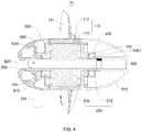
- embodiments of the present disclosure provide a direct-drive electric outboard engine 10 enabling to alleviate the above-described problems, which specifically includes an external rotor mechanism 100 and a stator mechanism 200; wherein the external rotor mechanism 100 includes an external rotor 110 and an impeller 120; the external rotor 110 is located outside the stator mechanism 200; and the impeller 120 is located outside the external rotor 110.
- the direct-drive electric outboard engine 10 in the embodiments of the present disclosure is an outboard engine with external rotor, and an outboard engine with external rotor outputs a larger torque than an outboard engine with internal rotor, hence having a higher load capacity.
- multiple impellers 120 may be simply used for performing low-speed driving directly.
- the impeller 120 is directly mounted at the external rotor 110, thus transmission (drive) parts between the impeller 120 and the external rotor 110 are omitted and the impeller 120 can directly rotate on the maximum outside diameter of the external rotor 110, which effectively increases the rotation radius of the impeller 120 and avoids the problem of the engine body's resistance on passing water, thereby the area of the cavitation region is reduced with less cavitation produced, the transmission (drive) efficiency is improved, the damage to the propeller from cavitation erosion is reduced and the transmission parts between the impeller 120 and the electric engine in the structure of the existing outboard engine are omitted.
- the rev is higher compared with the speed change method with gearbox, meanwhile, drop range of the rev is smaller than that of the electric engine with internal rotor, and the range of speed regulation is wider, thus alleviating the deficiency of low rev of common outboard engines with external rotors.
- the same is also applicable to ships demanding traveling in high speed such as speed boats.
- the direct-drive electric outboard engine 10 in the present embodiment can not only meet requirements for use on ships with high loads and low traveling speed, but also is applicable to ships demanding traveling in high speed such as speed boats, therefore the direct-drive electric outboard engine 10 in the present embodiment can simultaneously meet requirements on rev and torque from different types of ships.
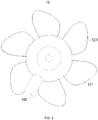
- the impeller 120 includes a plurality of vanes 121 which are provided separately, wherein each vane 121 is in fixed connection with the external rotor 110.
- a split design is employed on the impeller 120, which significantly lowers the difficulty of die sinking and the difficulty of processing of the impeller 120. Since the vanes 121 are vulnerable parts on the outboard engine, during its rotation underwater, damages due to collision with hard objects often occur, by employing a split structure, only one vane 121 is to be replaced in repairing, thus the repair cost is reduced.
- the clients may select the number of the vanes 121 by themselves to match the ships, for example, small ships demand high speed, thus a relatively small number of vanes 121 may be used; while heavy ships demand high torque and low rev, thus a relatively large number of vanes 121 may be used, thereby enhancing the flexibility of clients' choices.
- the external rotor 110 includes a permanent magnet 111 and a magnetic conducting ring 112, wherein the magnetic conducting ring 112 is provided outside the permanent magnet 111.
- the impeller 120 is provided in a circumferential direction of the magnetic conducting ring 112. After power on, magnetic flux is produced between the stator mechanism 200 and the permanent magnet 111 as well as the magnetic conducting ring 112, and the permanent magnet 111 and the magnetic conducting ring 112 start to rotate around the axis of the stator mechanism 200. The impeller 120 is driven to rotate directly by means of the rotation of the permanent magnet 111 and the magnetic conducting ring 112, to provide torque and speed for the ship.
- a plurality of raised portions 113 are evenly distributed on the outer surface of the magnetic conducting ring 112, and a groove 114 is formed between each two adjacent raised portions 113.
- the impeller 120 includes a plurality of vanes 121 which are provided separately, wherein each vane 121 is fixedly connected with the magnetic conducting ring 112 by means of the respective groove 114.
- Each vane 121 is mounted in the respective groove 114, since the vanes 121 are vulnerable parts in the outboard engine, during their rotation underwater, collision with hard objects often occurs, by mounting the vanes 121 inside the grooves 114 respectively, during the process in which the vanes 121 rotate and are subjected to forces, the raised portions 113 on the outer surface of the magnetic conducting ring 112 can bear a part of active force transmitted by the vanes 121, thus decreasing the probability of accidental loss of the vanes 121 during the rotation thereof, serving a function of protecting, fixing and supporting the vanes 121.
- each vane 121 includes a vane body 122 and a mounting block 123, wherein the vane body 122 and the mounting block 123 are integratedly formed, and the mounting block 123 is clamped (snapped) in the respective groove 114 and is in fixed connection with the magnetic conducting ring 112.
- the mode of integrated formation can increase the strength and hardness of the vanes 121, improving the service life thereof; and each mounting block 123, after being clamped in the respective groove 114, may firmly fix the respective vane 121 on the magnetic conducting ring 112 by means of bolt-tightening.
- the stator mechanism 200 includes a fixed shaft 210 and a stator 220 sleeved on the fixed shaft 210.
- the stator mechanism 200 is configured to cooperate with the external rotor mechanism 100, such that the external rotor mechanism 100 and the impeller 120 rotate around the axis of the fixed shaft 210 to provide rev and torque for the ship.
- the fixed shaft 210 is a hollow shaft.
- the design of the hollow shaft can realize simultaneous water-cooling of the stator mechanism 200 and the external rotor mechanism 100.
- the direct-drive electric outboard engine 10 in the present embodiment performs cooling simultaneously by means of the water-cooling of the hollow fixed shaft 210 and the exposure of the external rotor mechanism 100 in water, which remedies deficiency that only the stator mechanism 200 of the electric engine can be cooled with conventional structures, which is favorable for prolonging the service life of the direct-drive electric outboard engine 10, increasing power intensity of the electric engine and reducing temperature rise of the electric engine.
- the direct-drive electric outboard engine 10 further includes a first end cap 300 and a second end cap 400, wherein the first end cap 300 and the second end cap 400 are respectively provided at two ends of the stator mechanism 200.
- the first end cap 300 and the second end cap 400 can support the stator mechanism 200 to ameliorate force condition of the stator mechanism 200; and on the other hand, the first end cap 300 and the second end cap 400 further serve the function of blocking water from entering the stator mechanism 200 and alleviating water erosion on internal structures, prolonging the service life of the direct-drive electric outboard engine 10.
- the relative fixation between the external rotor mechanism 100 and the first end cap 300 as well as the second end cap 400 is achieved by snapping or bolt fixing.
- a first seal 1061 is provided between the first end cap 300 and the stator mechanism 200, and a second seal 1062 is provided between the second end cap 400 and the stator mechanism 200.
- first seal 1061 is provided between the first end cap 300 and the fixed shaft 210
- second seal 1062 is provided between the second end cap 400 and the fixed shaft 210
- first seal 1061 and the second seal 1062 may be realized by means of oil seal, and erosion damage on internal structures of the stator mechanism 200 caused by moisture can be reduced by oil seal.
- the direct-drive electric outboard engine 10 further includes a mounting base 500, wherein the mounting base 500 is sleeved on the fixed shaft 210 and is provided at a side of the first end cap 300 away from the external rotor 110.
- the mounting base 500 is configured to support and fix the stator mechanism 200, which can ensure the stability of the stator mechanism 200.
- the relative fixation between the mounting base 500 and the first end cap 300 is achieved by snapping or bolt fixing.
- the direct-drive electric outboard engine 10 further includes a first bearing 600 and a second bearing 700; wherein the first bearing 600 is located between the fixed shaft 210 and the first end cap 300; and the second bearing 700 is located between the fixed shaft 210 and the second end cap 400.
- the first bearing 600 and the second bearing 700 are respectively provided at two ends of the fixed shaft 210, which can ameliorate force condition of the fixed shaft 210 and prolong the service life of the fixed shaft 210.
- the direct-drive electric outboard engine 10 further includes a first fairwater 800 and a second fairwater 900, wherein the first fairwater 800 is mounted at one end of the stator mechanism 200; and the second fairwater 900 is mounted at the other end of the stator mechanism 200.
- the first fairwater 800 and the second fairwater 900 can ameliorate the force condition of the direct-drive electric outboard engine 10 under active force from water to reduce the resistance force to which the direct-drive electric outboard engine 10 is subjected during the process of advancing.
- the stator mechanism 200 includes a fixed shaft 210; wherein the fixed shaft 210 is a hollow shaft; the first fairwater 800 is provided with a first through hole 820, and the first through hole 820 communicates with one end of the fixed shaft 210; the second fairwater 900 is provided with a second through hole 920 and the second through hole 920 communicates with the other end of the fixed shaft 210.
- water may enter the fixed shaft 210 via the first through hole 820 and flow out via the second through hole 920.
- the direct-drive electric outboard engine 10 further includes a controller module 101; a first controller mounting area 810 is provided inside the first fairwater 800, wherein the controller module 101 is located in the first controller mounting area 810; or, a second controller mounting area 910 is provided inside the second fairwater 900 and the controller module 101 is provided in the second controller mounting area 910.
- the controller module 101 may be mounted in the first controller mounting area 810 or the second controller mounting area 910.
- An appropriate controller mounting area may be selected for the controller module based on different circuits and power source locations, with no need to add any other auxiliary equipment, thus the space may be utilized in a reasonable way and the dimension of the entire the direct-drive electric outboard engine 10 may be reduced.
- the controller module 101 may control rev, rotation direction and the like of the impeller 120.
- the second fairwater 900 is provided to be movable relative to the stator mechanism 200, wherein the second fairwater 900 can rotate following the rotation of the external rotor mechanism 100.
- cavitation region can be reduced and the occurrence of cavitation can be reduced, thus ameliorating the force condition of the direct-drive electric outboard engine 10 in the present embodiment under active force from water and reducing the resistance force to which the direct-drive electric outboard engine 10 is subjected during the process of advancing.
- the direct-drive electric outboard engine 10 further includes a third end cap 102, wherein the third end cap 102 is provided at an end of the stator mechanism 200, the third end cap 102 is relatively fixed to the external rotor 110, and the impeller 120 is in fixed connection with the third end cap 102.
- the third end cap 102, the permanent magnet 111 and the magnetic conducting ring 112 are each fixed relative to one another. After power on, magnetic flux is produced between the stator mechanism 200 and the permanent magnet 111 as well as the magnetic conducting ring 112, and the permanent magnet 111 and the magnetic conducting ring 112 start to rotate around the axis of the stator mechanism 200.
- the external rotor 110 drives the third end cap 102 to rotate, meanwhile the third end cap 102 drives the impeller 120 to rotate to provide torque and speed for the ship.
- the direct-drive electric outboard engine 10 further includes a fourth end cap 103 and a third fairwater 104, wherein the fourth end cap 103 is provided at one end of the stator mechanism 200 away from the third end cap 102, the third fairwater 104 is mounted at an end of the stator mechanism 200 close to the fourth end cap 103, and the third fairwater 104 and the stator mechanism 200 are relatively fixed.
- the third end cap 102 and the fourth end cap 103 are respectively provided at two ends of the stator mechanism 200, and are both running-fitted with the fixed shaft 210. After power on, each of the third end cap 102, the fourth end cap 103, the external rotor 110 and the impeller 120 rotate relative to the fixed shaft 210.
- the fourth end cap 103 may serve a certain support function for the stator mechanism 200, and the third fairwater 104 can ameliorate the force condition of the direct-drive electric outboard engine 10 under active force from water to reduce the resistance force to which the direct-drive electric outboard engine 10 is subjected during the process of advancing.
- embodiments of the present disclosure further provide a second direct-drive electric outboard engine 10, including an external rotor mechanism 100, a stator mechanism 200 and a third end cap 102; wherein the external rotor mechanism 100 includes an external rotor 110 and an impeller 120; the external rotor 110 is located outside the stator mechanism 200; the third end cap 102 is provided at an end of the stator mechanism 200, and the third end cap 102 is relatively fixed to the external rotor 110; and the impeller 120 is sleeved on the third end cap 102 and is in fixed connection with the third end cap 102.
- the third end cap 102 is relatively fixed to the external rotor 110 and rotates along with the external rotor 110.
- the third end cap 102 is relatively fixed to the impeller 120, magnetic flux is produced between the stator mechanism 200 and the permanent magnet 111 as well as the magnetic conducting ring 112, and the permanent magnet 111 and the magnetic conducting ring 112 start to rotate around the axis of the stator mechanism 200.
- the external rotor 110 drives the third end cap 102 to rotate, meanwhile the third end cap 102 drives the impeller 120 to rotate to provide torque and speed for the ship.
- the direct-drive electric outboard engine 10 further includes a fourth end cap 103 and a third fairwater 104, wherein the fourth end cap 103 is provided at an end of the stator mechanism 200 away from the third end cap 102, the third fairwater 104 is mounted at an end of the stator mechanism 200 close to the fourth end cap 103, and the third fairwater 104 and the stator mechanism 200 are relatively fixed.
- the third end cap 102 and the fourth end cap 103 are respectively provided at two ends of the stator mechanism 200, and are both running-fitted with the fixed shaft 210. After power on, each of the third end cap 102, the fourth end cap 103, the external rotor 110 and the impeller 120 rotate relative to the fixed shaft 210.
- the fourth end cap 103 may serve a certain support function for the stator mechanism 200, and the third fairwater 104 can ameliorate the force condition of the direct-drive electric outboard engine 10 under active force from water to reduce the resistance force to which the direct-drive electric outboard engine 10 is subjected during the process of advancing.
- embodiments of the present disclosure further provide an outboard engine system 20 including the above described direct-drive electric outboard engine 10.
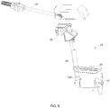
- the outboard engine system 20 further includes an operation control structure 21, a mounting structure 22, a support structure 23 and an anti-vortex baffle 24, wherein the operation control structure 21 is mounted on the support structure 23, the mounting structure 22 is connected with the support structure 23 and is configured to be mounted on a ship, the anti-vortex baffle 24 is mounted on the support structure 23, and the direct-drive electric outboard engine 10 is mounted on the support structure 23.
- the first fairwater 800 is provided thereon with a mounting portion 105, wherein the mounting portion 105 is in fixed connection with the support structure 23;
- the third fairwater 104 is provided thereon with a mounting portion 105, wherein the mounting portion 105 is in fixed connection with the support structure 23.
- the direction indicated by the arrow below the direct-drive electric outboard engine 10 is the direction of passing water.
- the direct-drive electric outboard engine 10 as illustrated in FIG. 1-FIG. 3 includes a first fairwater 800, an external rotor mechanism 100 and a second fairwater 900, wherein the external rotor mechanism 100 is located between the first fairwater 800 and the second fairwater 900, the first fairwater 800 is provided thereon with a mounting portion 105 and a first through hole 820, the external rotor mechanism 100 includes an impeller 120, the second fairwater 900 is provided with a second through hole 920, and the number of vanes 121 is 6.
- the direct-drive electric outboard engine 10 as illustrated in FIG. 4 includes an external rotor mechanism 100, a stator mechanism 200, a first end cap 300, a second end cap 400, a mounting base 500, a first bearing 600, a second bearing 700, a first fairwater 800 and a second fairwater 900; wherein the external rotor mechanism 100 includes an external rotor 110 and an impeller 120, wherein the external rotor 110 includes a permanent magnet 111 and a magnetic conducting ring 112, the impeller 120 includes a plurality of vanes 121, and the stator mechanism 200 includes a fixed shaft 210 and a stator 220; wherein the stator 220 is located outside the fixed shaft 210, the permanent magnet 111 is located outside the stator 220, the magnetic conducting ring 112 is located outside the permanent magnet 111, and the vanes 121 are located outside the magnetic conducting ring 112; the first end cap 300 and the second end cap 400 are respectively mounted at two ends of the stator mechanism 200,
- Each vane 121 includes a vane body 122 and a mounting block 123 which are integratedly formed, wherein the mounting block 123 is clamped (snapped) in the respective groove 114 and is relatively fixed to the magnetic conducting ring 112.
- the direct-drive electric outboard engine 10 as illustrated in FIG. 7 and FIG. 8 includes an external rotor mechanism 100, a stator mechanism 200, a third end cap 102, a fourth end cap 103 and a third fairwater 104; wherein the external rotor mechanism 100 includes an external rotor 110 and an impeller 120, the external rotor 110 includes a permanent magnet 111 and a magnetic conducting ring 112, and the stator mechanism 200 includes a fixed shaft 210 and a stator 220; wherein the stator 220 is located outside the fixed shaft 210, the permanent magnet 111 is located outside the stator 220, the magnetic conducting ring 112 is located outside the permanent magnetic 111, the third end cap 102 and the fourth end cap 103 are respectively provided at two ends of the stator mechanism 200, the third end cap 102 and the fourth end cap 103 are both relatively fixed to the external rotor 110 and are both running-fitted with the fixed shaft 210, the impeller 120 is slee
- the outboard engine system 20 as illustrated in FIG. 9 includes an operation control structure 21, a mounting structure 22, a support structure 23, an anti-vortex baffle 24 and a direct-drive electric outboard engine 10, wherein the operation control structure 21 is mounted on the support structure 23, the mounting structure 22 is connected with the support structure 23 and is configured to be mounted on a ship, the anti-vortex baffle 24 is mounted on the support structure 23, and the direct-drive electric outboard engine 10 is mounted on the support structure 23 by means of the mounting portion 105.
- the present disclosure provides a direct-drive electric outboard engine and an outboard engine system with high drive efficiency and strong load capacity, enabling to simultaneously meet the requirements on rev and torque from various types of ships.
Landscapes
- Engineering & Computer Science (AREA)
- Power Engineering (AREA)
- Chemical & Material Sciences (AREA)
- Combustion & Propulsion (AREA)
- Mechanical Engineering (AREA)
- Ocean & Marine Engineering (AREA)
- Connection Of Motors, Electrical Generators, Mechanical Devices, And The Like (AREA)
Applications Claiming Priority (1)
| Application Number | Priority Date | Filing Date | Title |
|---|---|---|---|
| CN201810782661.2A CN108639298A (zh) | 2018-07-16 | 2018-07-16 | 一种直驱式电动舷外机 |
Publications (2)
| Publication Number | Publication Date |
|---|---|
| EP3598614A1 true EP3598614A1 (fr) | 2020-01-22 |
| EP3598614B1 EP3598614B1 (fr) | 2021-09-08 |
Family
ID=63751338
Family Applications (1)
| Application Number | Title | Priority Date | Filing Date |
|---|---|---|---|
| EP19175224.5A Not-in-force EP3598614B1 (fr) | 2018-07-16 | 2019-05-17 | Moteur extérieur électrique à commande directe et système de moteur extérieur |
Country Status (3)
| Country | Link |
|---|---|
| US (1) | US10940928B2 (fr) |
| EP (1) | EP3598614B1 (fr) |
| CN (1) | CN108639298A (fr) |
Families Citing this family (9)
| Publication number | Priority date | Publication date | Assignee | Title |
|---|---|---|---|---|
| US20180229825A1 (en) * | 2014-05-01 | 2018-08-16 | Blue Robotics Inc. | Submersible electric thruster |
| NO20191370A1 (no) * | 2019-11-18 | 2021-05-19 | Olav Skyllingstad | Elektrisk batteridrevet motor og drivlinje for fremdrift av mindre båter |
| CN111547216B (zh) * | 2020-04-09 | 2022-07-26 | 武汉船用机械有限责任公司 | 吊舱推进器及其推进电机定子的安装方法 |
| US11685491B2 (en) * | 2020-12-01 | 2023-06-27 | City University Of Hong Kong | Hetero-stiffness robotic device |
| US12428117B2 (en) | 2021-10-25 | 2025-09-30 | Brunswick Corporation | Marine propulsion devices having electric motors and methods for making marine propulsion devices having electric motors |
| US12179899B2 (en) * | 2021-12-14 | 2024-12-31 | Brunswick Corporation | Marine drive lower unit having extension leg |
| US12275511B2 (en) | 2022-02-14 | 2025-04-15 | Brunswick Corporation | Marine drive having vented lower unit |
| CN114987729B (zh) * | 2022-05-30 | 2024-03-26 | 中国船舶重工集团公司第七一九研究所 | 集成电机推进装置及船舶 |
| US12466531B1 (en) | 2022-11-04 | 2025-11-11 | Brunswick Corporation | Marine drive lower unit having seal device |
Citations (7)
| Publication number | Priority date | Publication date | Assignee | Title |
|---|---|---|---|---|
| GB2050525A (en) * | 1979-03-13 | 1981-01-07 | Plot Ltd C | A Generator |
| JPS63247197A (ja) * | 1987-04-02 | 1988-10-13 | Yokogawa Electric Corp | 船舶用電気推進システム |
| US6485339B1 (en) * | 1997-07-21 | 2002-11-26 | Siemens Aktiengesellschaft | Electric motor pod drive system for a vessel with a cooling device |
| EP2762402A2 (fr) * | 2013-01-30 | 2014-08-06 | Antti Tamminen | Propulsion pour navire |
| CN104443340A (zh) * | 2014-12-02 | 2015-03-25 | 刘亿明 | 一种水下推进装置及包含该装置的水下机器人 |
| KR20160052842A (ko) * | 2014-10-28 | 2016-05-13 | 현대중공업 주식회사 | 선박용 프로펠러 |
| US20170166288A1 (en) * | 2014-02-06 | 2017-06-15 | Brian CLAUS | A Magnetically Geared Electric Drive |
Family Cites Families (16)
| Publication number | Priority date | Publication date | Assignee | Title |
|---|---|---|---|---|
| JPS6177595A (ja) * | 1984-09-21 | 1986-04-21 | Nishi Nippon Riyuutai Giken:Kk | 非接触駆動式推進装置 |
| JPS62137297A (ja) * | 1985-12-10 | 1987-06-20 | Kaiyo Kagaku Gijutsu Center | 水密回転伝達装置 |
| US6638122B1 (en) * | 2000-03-31 | 2003-10-28 | Bombardier Motor Corporation Of America | Electric marine propulsion employing switched reluctance motor drive |
| DE20121672U1 (de) * | 2001-11-28 | 2003-02-20 | Siemens AG, 80333 München | Schiffsantrieb |
| DE10322275A1 (de) * | 2003-05-16 | 2004-12-02 | Siemens Ag | Kühlsystem für Elektrisches Antriebssystem mit Synchronmaschine mit Hochtemperatur-Supraleitender Feldwicklung für Propeller- und Jetantrieb mit besonders kleinen Durchmessern in schwimmenden Geräten |
| CN101383551B (zh) * | 2008-09-19 | 2010-10-20 | 哈尔滨工程大学 | 水下动力装置与负载连接的耦合装置 |
| CN101369767B (zh) * | 2008-10-07 | 2010-09-08 | 哈尔滨工程大学 | 水下一体化电机推进器 |
| CN101505076B (zh) * | 2009-03-11 | 2010-12-01 | 哈尔滨工程大学 | 水下球形电机推进器 |
| CN103818535B (zh) * | 2014-03-14 | 2016-04-13 | 中国船舶重工集团公司第七○二研究所 | 集成电机推进装置 |
| DK3483055T3 (da) * | 2014-05-01 | 2024-09-09 | Blue Robotics Inc | Undervandstæt elektrisk trykmotor |
| CN204056276U (zh) * | 2014-08-13 | 2014-12-31 | 北京巴付勒传动技术有限公司 | 船舶吊舱推进器 |
| EP3069985A1 (fr) * | 2015-03-20 | 2016-09-21 | ABB Oy | Récipient avec une coque et une unité de propulsion |
| CN105346696B (zh) * | 2015-11-19 | 2016-09-14 | 浙江大学 | 集成式对转桨推进器 |
| US10689073B2 (en) * | 2016-10-17 | 2020-06-23 | General Electric Company | Apparatus and system for marine propeller blade dovetail stress reduction |
| CN206968956U (zh) * | 2017-05-05 | 2018-02-06 | 天津深之蓝海洋设备科技有限公司 | 水下推进器以及潜水器 |
| CN208665517U (zh) * | 2018-07-16 | 2019-03-29 | 常州高尔登科技有限公司 | 一种直驱式电动舷外机 |
-
2018
- 2018-07-16 CN CN201810782661.2A patent/CN108639298A/zh active Pending
-
2019
- 2019-05-17 EP EP19175224.5A patent/EP3598614B1/fr not_active Not-in-force
- 2019-05-30 US US16/426,761 patent/US10940928B2/en not_active Expired - Fee Related
Patent Citations (7)
| Publication number | Priority date | Publication date | Assignee | Title |
|---|---|---|---|---|
| GB2050525A (en) * | 1979-03-13 | 1981-01-07 | Plot Ltd C | A Generator |
| JPS63247197A (ja) * | 1987-04-02 | 1988-10-13 | Yokogawa Electric Corp | 船舶用電気推進システム |
| US6485339B1 (en) * | 1997-07-21 | 2002-11-26 | Siemens Aktiengesellschaft | Electric motor pod drive system for a vessel with a cooling device |
| EP2762402A2 (fr) * | 2013-01-30 | 2014-08-06 | Antti Tamminen | Propulsion pour navire |
| US20170166288A1 (en) * | 2014-02-06 | 2017-06-15 | Brian CLAUS | A Magnetically Geared Electric Drive |
| KR20160052842A (ko) * | 2014-10-28 | 2016-05-13 | 현대중공업 주식회사 | 선박용 프로펠러 |
| CN104443340A (zh) * | 2014-12-02 | 2015-03-25 | 刘亿明 | 一种水下推进装置及包含该装置的水下机器人 |
Also Published As
| Publication number | Publication date |
|---|---|
| CN108639298A (zh) | 2018-10-12 |
| US20200017183A1 (en) | 2020-01-16 |
| EP3598614B1 (fr) | 2021-09-08 |
| US10940928B2 (en) | 2021-03-09 |
Similar Documents
| Publication | Publication Date | Title |
|---|---|---|
| US10940928B2 (en) | Direct-drive electric outboard engine and outboard engine system | |
| EP1010614B1 (fr) | Module de propulsion et de gouverne pour navires de guerre | |
| US6231407B1 (en) | Ship propulsion with a gondola-like synchronous motor | |
| US5185545A (en) | Dual propeller shock resistant submersible propulsor unit | |
| AU744424B2 (en) | Electric motor pod drive system for a vessel with a cooling device | |
| US7061148B2 (en) | Device for cooling an electrical machine, in particular a synchronous electrical machine having permanent magnets | |
| US6312298B1 (en) | Electromotive drive system for a ship | |
| US20160344247A1 (en) | Motor having cooling structure | |
| CA2828658C (fr) | Bateau | |
| US6411000B1 (en) | Motor with a cooling means | |
| US20250033753A1 (en) | An outboard for watercraft | |
| JP2023526553A (ja) | レトロフィットハイブリッド推進システム用分割型電気機械 | |
| KR100518087B1 (ko) | 선박용 전동 구동 장치 | |
| US10651712B2 (en) | Rotor for an electrical machine | |
| US8517785B2 (en) | Vessel propulsion system for watercraft | |
| US20190214882A1 (en) | Sleeve and shaft for an electrical machine | |
| WO1999036312A3 (fr) | Dispositif d'entrainement electrique pour bateaux | |
| KR20140088266A (ko) | 전동기의 회전자 구조 | |
| EP4528992A1 (fr) | Système de refroidissement de moteur électrique, moteur électrique et rotor associé | |
| KR20020063580A (ko) | 용량이 다른 두 개의 구동 모터를 구비한, 선박용 구동 장치 | |
| CN217607612U (zh) | 采用水套冷却的穿轴式永磁电机 | |
| JPH05310185A (ja) | 水中推進装置 | |
| WO2019003199A1 (fr) | Système de propulsion pour navire marin | |
| CN208377033U (zh) | 一种应用于船外机中的螺旋桨保护套 | |
| CN208665517U (zh) | 一种直驱式电动舷外机 |
Legal Events
| Date | Code | Title | Description |
|---|---|---|---|
| PUAI | Public reference made under article 153(3) epc to a published international application that has entered the european phase |
Free format text: ORIGINAL CODE: 0009012 |
|
| STAA | Information on the status of an ep patent application or granted ep patent |
Free format text: STATUS: REQUEST FOR EXAMINATION WAS MADE |
|
| STAA | Information on the status of an ep patent application or granted ep patent |
Free format text: STATUS: EXAMINATION IS IN PROGRESS |
|
| 17P | Request for examination filed |
Effective date: 20190517 |
|
| AK | Designated contracting states |
Kind code of ref document: A1 Designated state(s): AL AT BE BG CH CY CZ DE DK EE ES FI FR GB GR HR HU IE IS IT LI LT LU LV MC MK MT NL NO PL PT RO RS SE SI SK SM TR |
|
| AX | Request for extension of the european patent |
Extension state: BA ME |
|
| 17Q | First examination report despatched |
Effective date: 20200110 |
|
| RIC1 | Information provided on ipc code assigned before grant |
Ipc: B63H 20/14 20060101ALI20210122BHEP Ipc: H02K 1/18 20060101ALI20210122BHEP Ipc: H02K 7/14 20060101AFI20210122BHEP Ipc: B63H 21/17 20060101ALI20210122BHEP Ipc: H02K 9/197 20060101ALI20210122BHEP Ipc: H02K 5/20 20060101ALI20210122BHEP Ipc: B63H 1/20 20060101ALI20210122BHEP |
|
| GRAP | Despatch of communication of intention to grant a patent |
Free format text: ORIGINAL CODE: EPIDOSNIGR1 |
|
| STAA | Information on the status of an ep patent application or granted ep patent |
Free format text: STATUS: GRANT OF PATENT IS INTENDED |
|
| INTG | Intention to grant announced |
Effective date: 20210325 |
|
| GRAS | Grant fee paid |
Free format text: ORIGINAL CODE: EPIDOSNIGR3 |
|
| GRAA | (expected) grant |
Free format text: ORIGINAL CODE: 0009210 |
|
| STAA | Information on the status of an ep patent application or granted ep patent |
Free format text: STATUS: THE PATENT HAS BEEN GRANTED |
|
| AK | Designated contracting states |
Kind code of ref document: B1 Designated state(s): AL AT BE BG CH CY CZ DE DK EE ES FI FR GB GR HR HU IE IS IT LI LT LU LV MC MK MT NL NO PL PT RO RS SE SI SK SM TR |
|
| REG | Reference to a national code |
Ref country code: GB Ref legal event code: FG4D |
|
| REG | Reference to a national code |
Ref country code: CH Ref legal event code: EP Ref country code: AT Ref legal event code: REF Ref document number: 1429446 Country of ref document: AT Kind code of ref document: T Effective date: 20210915 |
|
| REG | Reference to a national code |
Ref country code: DE Ref legal event code: R096 Ref document number: 602019007460 Country of ref document: DE |
|
| REG | Reference to a national code |
Ref country code: IE Ref legal event code: FG4D |
|
| REG | Reference to a national code |
Ref country code: LT Ref legal event code: MG9D |
|
| REG | Reference to a national code |
Ref country code: NL Ref legal event code: MP Effective date: 20210908 |
|
| PG25 | Lapsed in a contracting state [announced via postgrant information from national office to epo] |
Ref country code: HR Free format text: LAPSE BECAUSE OF FAILURE TO SUBMIT A TRANSLATION OF THE DESCRIPTION OR TO PAY THE FEE WITHIN THE PRESCRIBED TIME-LIMIT Effective date: 20210908 Ref country code: NO Free format text: LAPSE BECAUSE OF FAILURE TO SUBMIT A TRANSLATION OF THE DESCRIPTION OR TO PAY THE FEE WITHIN THE PRESCRIBED TIME-LIMIT Effective date: 20211208 Ref country code: LT Free format text: LAPSE BECAUSE OF FAILURE TO SUBMIT A TRANSLATION OF THE DESCRIPTION OR TO PAY THE FEE WITHIN THE PRESCRIBED TIME-LIMIT Effective date: 20210908 Ref country code: BG Free format text: LAPSE BECAUSE OF FAILURE TO SUBMIT A TRANSLATION OF THE DESCRIPTION OR TO PAY THE FEE WITHIN THE PRESCRIBED TIME-LIMIT Effective date: 20211208 Ref country code: SE Free format text: LAPSE BECAUSE OF FAILURE TO SUBMIT A TRANSLATION OF THE DESCRIPTION OR TO PAY THE FEE WITHIN THE PRESCRIBED TIME-LIMIT Effective date: 20210908 Ref country code: RS Free format text: LAPSE BECAUSE OF FAILURE TO SUBMIT A TRANSLATION OF THE DESCRIPTION OR TO PAY THE FEE WITHIN THE PRESCRIBED TIME-LIMIT Effective date: 20210908 Ref country code: ES Free format text: LAPSE BECAUSE OF FAILURE TO SUBMIT A TRANSLATION OF THE DESCRIPTION OR TO PAY THE FEE WITHIN THE PRESCRIBED TIME-LIMIT Effective date: 20210908 Ref country code: FI Free format text: LAPSE BECAUSE OF FAILURE TO SUBMIT A TRANSLATION OF THE DESCRIPTION OR TO PAY THE FEE WITHIN THE PRESCRIBED TIME-LIMIT Effective date: 20210908 |
|
| REG | Reference to a national code |
Ref country code: AT Ref legal event code: MK05 Ref document number: 1429446 Country of ref document: AT Kind code of ref document: T Effective date: 20210908 |
|
| PG25 | Lapsed in a contracting state [announced via postgrant information from national office to epo] |
Ref country code: LV Free format text: LAPSE BECAUSE OF FAILURE TO SUBMIT A TRANSLATION OF THE DESCRIPTION OR TO PAY THE FEE WITHIN THE PRESCRIBED TIME-LIMIT Effective date: 20210908 Ref country code: GR Free format text: LAPSE BECAUSE OF FAILURE TO SUBMIT A TRANSLATION OF THE DESCRIPTION OR TO PAY THE FEE WITHIN THE PRESCRIBED TIME-LIMIT Effective date: 20211209 |
|
| PG25 | Lapsed in a contracting state [announced via postgrant information from national office to epo] |
Ref country code: AT Free format text: LAPSE BECAUSE OF FAILURE TO SUBMIT A TRANSLATION OF THE DESCRIPTION OR TO PAY THE FEE WITHIN THE PRESCRIBED TIME-LIMIT Effective date: 20210908 |
|
| PG25 | Lapsed in a contracting state [announced via postgrant information from national office to epo] |
Ref country code: IS Free format text: LAPSE BECAUSE OF FAILURE TO SUBMIT A TRANSLATION OF THE DESCRIPTION OR TO PAY THE FEE WITHIN THE PRESCRIBED TIME-LIMIT Effective date: 20220108 Ref country code: SM Free format text: LAPSE BECAUSE OF FAILURE TO SUBMIT A TRANSLATION OF THE DESCRIPTION OR TO PAY THE FEE WITHIN THE PRESCRIBED TIME-LIMIT Effective date: 20210908 Ref country code: SK Free format text: LAPSE BECAUSE OF FAILURE TO SUBMIT A TRANSLATION OF THE DESCRIPTION OR TO PAY THE FEE WITHIN THE PRESCRIBED TIME-LIMIT Effective date: 20210908 Ref country code: RO Free format text: LAPSE BECAUSE OF FAILURE TO SUBMIT A TRANSLATION OF THE DESCRIPTION OR TO PAY THE FEE WITHIN THE PRESCRIBED TIME-LIMIT Effective date: 20210908 Ref country code: PT Free format text: LAPSE BECAUSE OF FAILURE TO SUBMIT A TRANSLATION OF THE DESCRIPTION OR TO PAY THE FEE WITHIN THE PRESCRIBED TIME-LIMIT Effective date: 20220110 Ref country code: PL Free format text: LAPSE BECAUSE OF FAILURE TO SUBMIT A TRANSLATION OF THE DESCRIPTION OR TO PAY THE FEE WITHIN THE PRESCRIBED TIME-LIMIT Effective date: 20210908 Ref country code: NL Free format text: LAPSE BECAUSE OF FAILURE TO SUBMIT A TRANSLATION OF THE DESCRIPTION OR TO PAY THE FEE WITHIN THE PRESCRIBED TIME-LIMIT Effective date: 20210908 Ref country code: EE Free format text: LAPSE BECAUSE OF FAILURE TO SUBMIT A TRANSLATION OF THE DESCRIPTION OR TO PAY THE FEE WITHIN THE PRESCRIBED TIME-LIMIT Effective date: 20210908 Ref country code: CZ Free format text: LAPSE BECAUSE OF FAILURE TO SUBMIT A TRANSLATION OF THE DESCRIPTION OR TO PAY THE FEE WITHIN THE PRESCRIBED TIME-LIMIT Effective date: 20210908 Ref country code: AL Free format text: LAPSE BECAUSE OF FAILURE TO SUBMIT A TRANSLATION OF THE DESCRIPTION OR TO PAY THE FEE WITHIN THE PRESCRIBED TIME-LIMIT Effective date: 20210908 |
|
| REG | Reference to a national code |
Ref country code: DE Ref legal event code: R097 Ref document number: 602019007460 Country of ref document: DE |
|
| PLBE | No opposition filed within time limit |
Free format text: ORIGINAL CODE: 0009261 |
|
| STAA | Information on the status of an ep patent application or granted ep patent |
Free format text: STATUS: NO OPPOSITION FILED WITHIN TIME LIMIT |
|
| PG25 | Lapsed in a contracting state [announced via postgrant information from national office to epo] |
Ref country code: DK Free format text: LAPSE BECAUSE OF FAILURE TO SUBMIT A TRANSLATION OF THE DESCRIPTION OR TO PAY THE FEE WITHIN THE PRESCRIBED TIME-LIMIT Effective date: 20210908 |
|
| 26N | No opposition filed |
Effective date: 20220609 |
|
| PG25 | Lapsed in a contracting state [announced via postgrant information from national office to epo] |
Ref country code: SI Free format text: LAPSE BECAUSE OF FAILURE TO SUBMIT A TRANSLATION OF THE DESCRIPTION OR TO PAY THE FEE WITHIN THE PRESCRIBED TIME-LIMIT Effective date: 20210908 |
|
| REG | Reference to a national code |
Ref country code: DE Ref legal event code: R119 Ref document number: 602019007460 Country of ref document: DE |
|
| REG | Reference to a national code |
Ref country code: CH Ref legal event code: PL |
|
| REG | Reference to a national code |
Ref country code: BE Ref legal event code: MM Effective date: 20220531 |
|
| PG25 | Lapsed in a contracting state [announced via postgrant information from national office to epo] |
Ref country code: MC Free format text: LAPSE BECAUSE OF FAILURE TO SUBMIT A TRANSLATION OF THE DESCRIPTION OR TO PAY THE FEE WITHIN THE PRESCRIBED TIME-LIMIT Effective date: 20210908 Ref country code: LU Free format text: LAPSE BECAUSE OF NON-PAYMENT OF DUE FEES Effective date: 20220517 Ref country code: LI Free format text: LAPSE BECAUSE OF NON-PAYMENT OF DUE FEES Effective date: 20220531 Ref country code: IT Free format text: LAPSE BECAUSE OF FAILURE TO SUBMIT A TRANSLATION OF THE DESCRIPTION OR TO PAY THE FEE WITHIN THE PRESCRIBED TIME-LIMIT Effective date: 20210908 Ref country code: CH Free format text: LAPSE BECAUSE OF NON-PAYMENT OF DUE FEES Effective date: 20220531 |
|
| PG25 | Lapsed in a contracting state [announced via postgrant information from national office to epo] |
Ref country code: IE Free format text: LAPSE BECAUSE OF NON-PAYMENT OF DUE FEES Effective date: 20220517 Ref country code: FR Free format text: LAPSE BECAUSE OF NON-PAYMENT OF DUE FEES Effective date: 20220531 |
|
| PG25 | Lapsed in a contracting state [announced via postgrant information from national office to epo] |
Ref country code: DE Free format text: LAPSE BECAUSE OF NON-PAYMENT OF DUE FEES Effective date: 20221201 Ref country code: BE Free format text: LAPSE BECAUSE OF NON-PAYMENT OF DUE FEES Effective date: 20220531 |
|
| GBPC | Gb: european patent ceased through non-payment of renewal fee |
Effective date: 20230517 |
|
| PG25 | Lapsed in a contracting state [announced via postgrant information from national office to epo] |
Ref country code: MK Free format text: LAPSE BECAUSE OF FAILURE TO SUBMIT A TRANSLATION OF THE DESCRIPTION OR TO PAY THE FEE WITHIN THE PRESCRIBED TIME-LIMIT Effective date: 20210908 Ref country code: CY Free format text: LAPSE BECAUSE OF FAILURE TO SUBMIT A TRANSLATION OF THE DESCRIPTION OR TO PAY THE FEE WITHIN THE PRESCRIBED TIME-LIMIT Effective date: 20210908 Ref country code: GB Free format text: LAPSE BECAUSE OF NON-PAYMENT OF DUE FEES Effective date: 20230517 |
|
| PG25 | Lapsed in a contracting state [announced via postgrant information from national office to epo] |
Ref country code: HU Free format text: LAPSE BECAUSE OF FAILURE TO SUBMIT A TRANSLATION OF THE DESCRIPTION OR TO PAY THE FEE WITHIN THE PRESCRIBED TIME-LIMIT; INVALID AB INITIO Effective date: 20190517 |
|
| PG25 | Lapsed in a contracting state [announced via postgrant information from national office to epo] |
Ref country code: TR Free format text: LAPSE BECAUSE OF FAILURE TO SUBMIT A TRANSLATION OF THE DESCRIPTION OR TO PAY THE FEE WITHIN THE PRESCRIBED TIME-LIMIT Effective date: 20210908 |
|
| PG25 | Lapsed in a contracting state [announced via postgrant information from national office to epo] |
Ref country code: MT Free format text: LAPSE BECAUSE OF FAILURE TO SUBMIT A TRANSLATION OF THE DESCRIPTION OR TO PAY THE FEE WITHIN THE PRESCRIBED TIME-LIMIT Effective date: 20210908 |