EP3598894A1 - Appareil et procédé de transport d'objets sphériques souples - Google Patents
Appareil et procédé de transport d'objets sphériques souples Download PDFInfo
- Publication number
- EP3598894A1 EP3598894A1 EP19187712.5A EP19187712A EP3598894A1 EP 3598894 A1 EP3598894 A1 EP 3598894A1 EP 19187712 A EP19187712 A EP 19187712A EP 3598894 A1 EP3598894 A1 EP 3598894A1
- Authority
- EP
- European Patent Office
- Prior art keywords
- conveying
- peripheral part
- fish
- rotary member
- removing roller
- Prior art date
- Legal status (The legal status is an assumption and is not a legal conclusion. Google has not performed a legal analysis and makes no representation as to the accuracy of the status listed.)
- Withdrawn
Links
- 238000000034 method Methods 0.000 title claims description 17
- 230000002093 peripheral effect Effects 0.000 claims abstract description 157
- XLYOFNOQVPJJNP-UHFFFAOYSA-N water Substances O XLYOFNOQVPJJNP-UHFFFAOYSA-N 0.000 claims abstract description 116
- 238000011144 upstream manufacturing Methods 0.000 claims abstract description 11
- 235000013601 eggs Nutrition 0.000 abstract description 158
- 241000251468 Actinopterygii Species 0.000 abstract description 146
- 235000019688 fish Nutrition 0.000 description 139
- 108090000623 proteins and genes Proteins 0.000 description 39
- 238000002347 injection Methods 0.000 description 21
- 239000007924 injection Substances 0.000 description 21
- 238000009395 breeding Methods 0.000 description 8
- 230000001488 breeding effect Effects 0.000 description 8
- 239000000243 solution Substances 0.000 description 8
- 230000005484 gravity Effects 0.000 description 6
- 239000000463 material Substances 0.000 description 6
- 241000252212 Danio rerio Species 0.000 description 5
- 239000000126 substance Substances 0.000 description 4
- 238000000520 microinjection Methods 0.000 description 3
- 102000004169 proteins and genes Human genes 0.000 description 3
- 239000013076 target substance Substances 0.000 description 3
- 230000032823 cell division Effects 0.000 description 2
- 238000009509 drug development Methods 0.000 description 2
- 230000009191 jumping Effects 0.000 description 2
- 239000002904 solvent Substances 0.000 description 2
- 241000972773 Aulopiformes Species 0.000 description 1
- 239000004278 EU approved seasoning Substances 0.000 description 1
- 206010028980 Neoplasm Diseases 0.000 description 1
- 102000007056 Recombinant Fusion Proteins Human genes 0.000 description 1
- 108010008281 Recombinant Fusion Proteins Proteins 0.000 description 1
- 241000251539 Vertebrata <Metazoa> Species 0.000 description 1
- 238000013459 approach Methods 0.000 description 1
- 201000011510 cancer Diseases 0.000 description 1
- 239000003086 colorant Substances 0.000 description 1
- 230000000052 comparative effect Effects 0.000 description 1
- 239000003814 drug Substances 0.000 description 1
- 229940079593 drug Drugs 0.000 description 1
- 229940000406 drug candidate Drugs 0.000 description 1
- 235000013305 food Nutrition 0.000 description 1
- 239000002778 food additive Substances 0.000 description 1
- 235000013373 food additive Nutrition 0.000 description 1
- 235000011194 food seasoning agent Nutrition 0.000 description 1
- 230000014509 gene expression Effects 0.000 description 1
- 238000010353 genetic engineering Methods 0.000 description 1
- 210000001161 mammalian embryo Anatomy 0.000 description 1
- 238000004519 manufacturing process Methods 0.000 description 1
- 239000012528 membrane Substances 0.000 description 1
- 230000000149 penetrating effect Effects 0.000 description 1
- 231100000614 poison Toxicity 0.000 description 1
- 235000019515 salmon Nutrition 0.000 description 1
- 239000013535 sea water Substances 0.000 description 1
- 239000003440 toxic substance Substances 0.000 description 1
Images


Classifications
-
- A—HUMAN NECESSITIES
- A01—AGRICULTURE; FORESTRY; ANIMAL HUSBANDRY; HUNTING; TRAPPING; FISHING
- A01K—ANIMAL HUSBANDRY; AVICULTURE; APICULTURE; PISCICULTURE; FISHING; REARING OR BREEDING ANIMALS, NOT OTHERWISE PROVIDED FOR; NEW BREEDS OF ANIMALS
- A01K61/00—Culture of aquatic animals
- A01K61/10—Culture of aquatic animals of fish
- A01K61/17—Hatching, e.g. incubators
-
- B—PERFORMING OPERATIONS; TRANSPORTING
- B65—CONVEYING; PACKING; STORING; HANDLING THIN OR FILAMENTARY MATERIAL
- B65G—TRANSPORT OR STORAGE DEVICES, e.g. CONVEYORS FOR LOADING OR TIPPING, SHOP CONVEYOR SYSTEMS OR PNEUMATIC TUBE CONVEYORS
- B65G51/00—Conveying articles through pipes or tubes by fluid flow or pressure; Conveying articles over a flat surface, e.g. the base of a trough, by jets located in the surface
- B65G51/02—Directly conveying the articles, e.g. slips, sheets, stockings, containers or workpieces, by flowing gases
- B65G51/03—Directly conveying the articles, e.g. slips, sheets, stockings, containers or workpieces, by flowing gases over a flat surface or in troughs
-
- B—PERFORMING OPERATIONS; TRANSPORTING
- B65—CONVEYING; PACKING; STORING; HANDLING THIN OR FILAMENTARY MATERIAL
- B65G—TRANSPORT OR STORAGE DEVICES, e.g. CONVEYORS FOR LOADING OR TIPPING, SHOP CONVEYOR SYSTEMS OR PNEUMATIC TUBE CONVEYORS
- B65G47/00—Article or material-handling devices associated with conveyors; Methods employing such devices
- B65G47/02—Devices for feeding articles or materials to conveyors
- B65G47/04—Devices for feeding articles or materials to conveyors for feeding articles
- B65G47/12—Devices for feeding articles or materials to conveyors for feeding articles from disorderly-arranged article piles or from loose assemblages of articles
- B65G47/14—Devices for feeding articles or materials to conveyors for feeding articles from disorderly-arranged article piles or from loose assemblages of articles arranging or orientating the articles by mechanical or pneumatic means during feeding
- B65G47/1407—Devices for feeding articles or materials to conveyors for feeding articles from disorderly-arranged article piles or from loose assemblages of articles arranging or orientating the articles by mechanical or pneumatic means during feeding the articles being fed from a container, e.g. a bowl
- B65G47/1442—Devices for feeding articles or materials to conveyors for feeding articles from disorderly-arranged article piles or from loose assemblages of articles arranging or orientating the articles by mechanical or pneumatic means during feeding the articles being fed from a container, e.g. a bowl by means of movement of the bottom or a part of the wall of the container
- B65G47/1471—Movement in one direction, substantially outwards
-
- B—PERFORMING OPERATIONS; TRANSPORTING
- B65—CONVEYING; PACKING; STORING; HANDLING THIN OR FILAMENTARY MATERIAL
- B65G—TRANSPORT OR STORAGE DEVICES, e.g. CONVEYORS FOR LOADING OR TIPPING, SHOP CONVEYOR SYSTEMS OR PNEUMATIC TUBE CONVEYORS
- B65G2201/00—Indexing codes relating to handling devices, e.g. conveyors, characterised by the type of product or load being conveyed or handled
- B65G2201/02—Articles
- B65G2201/0214—Articles of special size, shape or weigh
-
- Y—GENERAL TAGGING OF NEW TECHNOLOGICAL DEVELOPMENTS; GENERAL TAGGING OF CROSS-SECTIONAL TECHNOLOGIES SPANNING OVER SEVERAL SECTIONS OF THE IPC; TECHNICAL SUBJECTS COVERED BY FORMER USPC CROSS-REFERENCE ART COLLECTIONS [XRACs] AND DIGESTS
- Y02—TECHNOLOGIES OR APPLICATIONS FOR MITIGATION OR ADAPTATION AGAINST CLIMATE CHANGE
- Y02A—TECHNOLOGIES FOR ADAPTATION TO CLIMATE CHANGE
- Y02A40/00—Adaptation technologies in agriculture, forestry, livestock or agroalimentary production
- Y02A40/80—Adaptation technologies in agriculture, forestry, livestock or agroalimentary production in fisheries management
- Y02A40/81—Aquaculture, e.g. of fish
Definitions
- the present invention relates to a soft spherical object conveying apparatus that conveys soft spherical objects such as fish eggs in a water tank and to a method for conveying soft spherical objects.
- the above-described fertilized eggs frequently undergo cell division, for example, at intervals of about 30 minutes, and therefore, in order to rapidly introduce a gene and obtain a desired fertilized egg, it is intended that a fertilized egg is processed with higher efficiency.
- the related arts disclosed in the above patent documents are based on the assumption of what is called batch processing in which the processing speed is restricted due to the use of a predetermined container, or the like, and therefore fertilized eggs are not processed in a state suitable for processing on a constant basis.
- the inventor of the present invention has studied a method for conveying fish eggs enabling predetermined processing to be performed on fish eggs with higher efficiency, and has found out that, by disposing, in a water tank into which fish eggs are introduced, a conveying rotary member having a plurality of housing recesses on the periphery thereof, and guiding the fish eggs to the housing recesses of the conveying rotary member, predetermined processing can be performed with higher efficiency on the fish eggs positioned in the housing recesses.
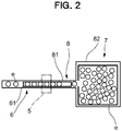
- a conveying gear 61 that intermittently rotates is disposed inside a water tank 8 filled with water up to the vicinity of the upper end thereof, and a gene injection unit 5 is arranged above the water tank 8.
- the inner thickness dimension of the water tank 8 is set to a dimension such that a plurality of the fish eggs e not allowed to lie side by side.
- a peripheral part of the conveying gear 61 is provided with a plurality of housing recesses 61a housing each one of the fish eggs.
- the fish eggs e introduced into the water tank 8 are guided to the peripheral part of the conveying gear 61 by a guide 60, and the fish eggs e are supplied to the housing recesses 61a of the conveying gear 61 one by one.
- the gene injection unit 5 injects a gene solution into the fish egg e separated and conveyed one by one by the housing recess 61a of the conveying gear 61.
- a guide member 163 is fixed above the conveying gear 61 in the water tank 8 to prevent the two or more fish eggs e from entering the single housing recess 61a of the conveying gear 61 and prevent the fish egg e having entered the housing recess 61a from jumping out.
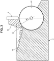
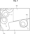
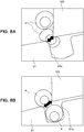
- the fish egg e moves to the housing recess 61a of the conveying gear 61, there is a problem in that the fish egg e is caught and crushed between a tooth tip of the conveying gear 61 and the guide member 163 in an area where the distance between the tooth tip of the conveying gear 61 and the guide member 163 is short as illustrated in FIG. 8A .
- the present invention has been made in view of the above problems and an object thereof is to provide a soft spherical object conveying apparatus and a method for conveying a soft spherical object, with which it is possible to prevent a soft spherical object, such as a fish egg, from being caught and crushed between a conveying rotary member such as a conveying gear, and a guide member when the soft spherical object is supplied to a housing recess of the conveying rotary member.
- the present invention takes the following measures in order to solve the above problems.
- a soft spherical object conveying apparatus includes: a water tank into which at least one soft spherical object is introduced; a conveying rotary member that rotates in the water tank and has a peripheral part provided with a plurality of housing recesses housing each one of the soft spherical objects; a guide member disposed along part of the peripheral part of the conveying rotary member in the water tank; and a removing roller that rotates on an upstream side of the guide member in the water tank in a rotation direction of the conveying rotary member, such that a part of the removing roller opposed to the peripheral part of the conveying rotary member moves in a direction away from the guide member.
- the removing roller rotates on the upstream side of the guide member in the water tank in the rotation direction of the conveying rotary member, whereby water flow is formed in the area where soft spherical objects are supplied to the peripheral part of the conveying rotary member in the water tank so that the soft spherical objects not housed in the housing recesses of the conveying rotary member are prevented from moving to the area where the peripheral part of the conveying rotary member and the outer peripheral surface of the removing roller are located close to each other.
- the soft spherical objects are brought into contact with the outer peripheral surface of the removing roller, whereby the soft spherical objects not housed in the housing recesses of the conveying rotary member are prevented from moving to the area where the peripheral part of the conveying rotary member and the outer peripheral surface of the removing roller are located close to each other. Therefore, it is possible to prevent the soft spherical object from being caught and crushed between the peripheral part of the conveying rotary member and the guide member when the soft spherical object moves to the housing recess of the conveying rotary member.
- a protrusion and a recess are formed on an outer peripheral surface of the removing roller.
- the soft spherical object conveying apparatus In the soft spherical object conveying apparatus according to the present invention, water flow is easily formed in the water tank as the removing roller rotates. Furthermore, by the soft spherical object contacting the outer peripheral surface of the removing roller, the soft spherical object easily moves in a direction away from the peripheral part of the conveying rotary member. Therefore, the soft spherical object can be effectively prevented from being caught and crushed between the peripheral part of the conveying rotary member and the guide member.
- a plurality of grooves extending along a thickness direction of the removing roller are formed on the outer peripheral surface of the removing roller.
- the soft spherical object conveying apparatus In the soft spherical object conveying apparatus according to the present invention, the soft spherical object can be more effectively prevented from being caught and crushed between the peripheral part of the conveying rotary member and the guide member.
- the conveying rotary member intermittently rotates so as to alternately repeat a rotating state and a stopped state, and the removing roller continuously rotates.
- the soft spherical object conveying apparatus since the removing roller continuously rotates while the conveying rotary member intermittently rotates, the soft spherical objects are easily supplied one by one to the housing recesses of the conveying rotary member in the water tank.
- the area in which the peripheral part of the conveying rotary member and the outer peripheral surface of the removing roller are located close to each other is a wedge-shaped area, and therefore, the water flow formed in the water tank by the rotation of the removing roller can effectively prevent the soft spherical objects not housed in the housing recesses of the conveying rotary member from moving to the area where the peripheral part of the conveying rotary member and the outer peripheral surface of the removing roller are located close to each other.
- a method for conveying a soft spherical object includes the steps of: conveying, in a water tank into which at least one soft spherical object is introduced, the soft spherical object by rotating a conveying rotary member having a peripheral part provided with a plurality of housing recesses housing and conveying the soft spherical object; and rotating a removing roller, disposed close to the peripheral part of the conveying rotary member, at a rotation velocity corresponding to a rotation velocity of the conveying rotary member such that a part of the removing roller opposed to the peripheral part of the conveying rotary member moves in a direction opposite to a movement direction of the peripheral part of the conveying rotary member.
- the water flow formed in the water tank by the rotation of the removing roller can prevent the soft spherical object from moving to the area where the peripheral part of the conveying rotary member and the outer peripheral surface of the removing roller are located close to each other.
- the method for conveying the soft spherical object includes the steps of: conveying, in a water tank into which at least one soft spherical object is introduced, the soft spherical object by rotating a conveying rotary member having a peripheral part provided with a plurality of housing recesses housing and conveying the soft spherical object; and forming water flow in a direction opposite to a movement direction of the peripheral part of the conveying rotary member by using a removing unit disposed close to the peripheral part of the conveying rotary member.
- water flow is formed in a direction opposite to the movement direction of the peripheral part of the conveying rotary member in the area close to the peripheral part of the conveying rotary member in the water tank, whereby the soft spherical objects not housed in the housing recesses of the conveying rotary member are prevented from moving to the area where the peripheral part of the conveying rotary member and the outer peripheral surface of the removing roller are located close to each other.
- the soft spherical object from being caught and crushed between the peripheral part of the conveying rotary member and the guide member when the soft spherical object moves to the housing recess of the conveying rotary member.
- a gene injection system 1 including a fish-egg conveying apparatus 6 is used to promptly introduce a gene solution containing a gene, which is a predetermined substance, into each of fertilized eggs, which are fish eggs e collected from a breeding water tank B. Then, in the fish egg e into which the gene solution has been injected, cell division is repeated and a protein derived from the base sequence of the introduced gene is synthesized. Then, the protein is collected, extracted, and purified in appropriate timing and is used for, for example, drug development study and mass production.
- the gene injection system 1 includes: a collected-egg conveying unit 2 that is continuous to the breeding water tank B; an unnecessary-material separating unit 3 that separates the conveyed fish eggs e from unnecessary materials such as breeding water, excrement, or remaining food; a vibration conveying unit 4 that conveys, mainly by vibration, the fish eggs e separated from the unnecessary materials; the fish-egg conveying apparatus 6 that conveys the fish eggs e conveyed by the vibration conveying unit 4, while arranging the fish eggs e in rows in a predetermined state; the gene injection unit 5 that injects the gene solution into each of the fish eggs e conveyed by the fish-egg conveying apparatus 6; and a selection and collection unit 7 for efficiently collecting the fish egg e into which the gene solution has been injected.
- a collected-egg conveying unit 2 that is continuous to the breeding water tank B
- an unnecessary-material separating unit 3 that separates the conveyed fish eggs e from unnecessary materials such as breeding water, excrement, or remaining food
- a zebrafish egg having substantially a spherical shape with a diameter of approximately 1 mm is used as an example of the fish egg e. Furthermore, since fish is a vertebrate, a protein in the form that can be used for drug development is easily obtained by gene introduction, and in particular, zebrafish is known as the type with which the fish eggs e, which are fertilized eggs, are efficiently obtained from the breeding water tank B.
- the collected-egg conveying unit 2 is, for example, a water-gutter shaped passage configured to have a sloped shape so as to efficiently collect the fish eggs e from the breeding water tanks B arranged in plurality in parallel and at multiple stages in a vertical direction. As well as the fish eggs e, the collected-egg conveying unit 2 simultaneously conveys, from the breeding water tanks B, the breeding water in which the fish is bred, and the fish eggs e and the breeding water are once stored in a tank T and then lifted by a pump P and guided to the unnecessary-material separating unit 3.
- the unnecessary-material separating unit 3 includes: a first net device 31 that allows the fish eggs e to pass therethrough and collects and removes unnecessary materials larger than the fish eggs e; a second net device 32 that is supported by the vibration conveying unit 4 and has a mesh that does not allow the fish eggs e to pass therethrough; and a clean-water ejection unit 33 that ejects clean water to the fish eggs e in the second net device 32.
- the vibration conveying unit 4 guides the fish eggs e to the water tank 8 by applying a predetermined vibration to the second net device 32.
- the fish eggs e to which the vibration is applied by the vibration conveying unit 4 are conveyed and introduced to the water tank 8 quickly and efficiently.
- the fish-egg conveying apparatus 6 arranges, in rows, the fish eggs e introduced into a region 81 of the water tank 8 such that the fish eggs e are easily processed by the gene injection unit 5.
- the gene injection unit 5 injects a gene solution into each of the fish eggs e conveyed by the fish-egg conveying apparatus 6.
- the selection and collection unit 7 conducts capturing the fish egg e with a camera (not illustrated), determines whether gene injection has succeeded/failed by image processing, conveys the determined fish eggs e to a different route (not illustrated), and then efficiently collects the fish egg e into which a gene has been injected from the fish-egg conveying apparatus 6 to a region 82 of the water tank 8.
- the gene injection unit 5, the fish-egg conveying apparatus 6, and the selection and collection unit 7 are provided in the water tank 8. Specifically, the gene injection unit 5 is disposed above the water tank 8, and the fish-egg conveying apparatus 6 and the selection and collection unit 7 are disposed inside the water tank 8.
- the water tank 8 includes: the region 81, the inner thickness dimension of which is set to a dimension such that a plurality of fish eggs e are not allowed to lie side by side in order to house the fish eggs e; and the region 82 for housing the fish eggs e on which predetermined processing has been performed.
- the water tank 8 has, in a planar view, substantially a T-shape in which the region 81 and the region 82 are connected. Further, the water tank 8 is filled with water up to the vicinity of the upper end thereof.
- the fish-egg conveying apparatus 6 includes: the conveying gear 61 to which the fish eggs e introduced into the water tank 8 are guided by the guide 60; an alignment pump 62 that ejects clean water toward the conveying gear 61; a guide member 63 disposed above the conveying gear 61; and a removing roller 64 that removes the fish eggs e from an area close to the guide member 63 in the peripheral part of the conveying gear 61. Therefore, the fish eggs e introduced into the region 81 are smoothly guided to the conveying gear 61 by clean water from the alignment pump 62.
- the conveying gear 61 is configured to be rotatable in the water tank 8 and has a plurality of the peripheral part provided with the housing recesses 61a housing each one of the fish egg e.
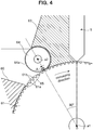
- the plurality of housing recesses 61a are provided at equal intervals in the circumferential direction in the peripheral part of the conveying gear 61. Therefore, in the peripheral part of the conveying gear 61, the housing recess 61a and the part where the housing recess 61a is not formed are alternately arranged. That is, as illustrated in FIG. 4 , the 100 housing recesses 61a and 100 tooth tips 61b are alternately arranged in the peripheral part of the conveying gear 61.
- the size and the number of the housing recesses 61a formed in the peripheral part of the conveying gear 61 may be changed in accordance with the size, or the like, of the fish egg e. Further, in the water tank 8, the conveying gear 61 is disposed in the region 81, the dimension of which is set such that a plurality of fish eggs e are not allowed to lie side by side, and the thickness of the conveying gear 61 is, for example, about one third of the thickness of the region 81.
- the direction in which the fish egg e housed in the housing recess 61a of the conveying gear 61 moves is referred to as the conveying direction of the fish egg e (simply, the conveying direction) in some cases.
- the guide member 63 is disposed along part of the peripheral part of the conveying gear 61 on the upstream side of the gene injection unit 5 in the conveying direction.
- the guide member 63 prevents the two or more fish eggs e from entering the single housing recess 61a of the conveying gear 61 and prevents the fish egg e having entered the housing recess 61a from jumping out.
- the part of the guide member 63 opposed to the peripheral part of the conveying gear 61 has substantially the same shape as the outer shape of the peripheral part of the conveying gear 61.
- a gap between the guide member 63 and the peripheral part of the conveying gear 61 is, for example, about one tenth of the diameter of the fish egg e, which is very small.
- the removing roller 64 is disposed on the upstream side of the guide member 63 in the conveying direction around the conveying gear 61.
- the part of the guide member 63 opposed to the outer peripheral surface of the removing roller 64 has substantially the same shape as that of the outer peripheral surface of the removing roller 64.
- the guide member 63 is disposed close to the peripheral part of the conveying gear 61 and the outer peripheral surface of the removing roller 64.
- the removing roller 64 is disposed in the water tank 8 so as to be close to the peripheral part of the conveying gear 61 on the upstream side of the guide member 63 in the conveying direction.
- the removing roller 64 rotates such that a part (a part A in FIG. 4 ) opposed to the peripheral part of the conveying gear 61 moves in a direction away from the guide member 63.
- the peripheral part of the conveying gear 61 moves in the conveying direction
- the outer peripheral surface of the removing roller 64 moves in the direction opposite to the conveying direction. Projections and recesses are formed on the outer peripheral surface of the removing roller 64 by knurling.
- a plurality of grooves 64a extending along the thickness direction thereof are formed on the outer peripheral surface of the removing roller 64.
- projections and recesses are formed by knurling of, for example, flat module 0.2 and flat module 0.3; however, the type of knurling is not limited thereto.
- each of the conveying gear 61 and the removing roller 64 is precisely controlled by driving an AC servomotor via a motor driver.
- the conveying gear 61 is controlled to intermittently rotate so as to alternately repeat a rotating state and a stopped state. That is, the conveying gear 61 is controlled to intermittently rotate such that the fish egg e positioned in the housing recess 61a is supplied to the gene injection unit 5.
- the removing roller 64 is controlled to continuously rotate.
- the removing roller 64 is controlled to continuously rotate at a predetermined rotation velocity.
- the rotation velocity of the removing roller 64 corresponds to the rotation velocity of the conveying gear 61 (the moving velocity (peripheral velocity) of the outer peripheral surface of the conveying gear 61)
- the fish egg e is more properly supplied to the housing recess 61a of the conveying gear 61.
- the conveying gear 61 intermittently rotates by alternately repeating the rotating state and the stopped state
- the rotation velocity of the conveying gear 61 is the rotation velocity in the rotating state.
- the water flow formed in the water tank 8 by the rotation of the removing roller 64 can prevent the fish egg e from moving to an area where the peripheral part of the conveying gear 61 and the outer peripheral surface of the removing roller 64 are located close to each other, and the contact between the fish egg e and the outer peripheral surface of the removing roller 64 can prevent the fish egg e from moving to an area where the peripheral part of the conveying gear 61 and the outer peripheral surface of the removing roller 64 are located close to each other.
- it is sometimes preferable that the fish eggs e are removed by the water flow without being in contact with the outer peripheral surface of the removing roller 64.
- the rotation velocity of the conveying gear 61 in the water tank 8 increases, the amount of the fish eggs e in the water tank 8 and the amount of the conveyed fish eggs e increase. Therefore, there is a high possibility of contact with the outer peripheral surface of the removing roller 64. Thus, it is considered that the rotation velocity of the removing roller 64 is increased in accordance with an increase in the rotation velocity of the conveying gear 61, whereby the water flow formed by the removing roller 64 is increased.
- the gene injection unit 5 is disposed vertically above a rotation center a1 of the conveying gear 61, while the removing roller 64 is disposed such that a straight line passing through a rotation center a2 of the removing roller 64 and the rotation center a1 of the conveying gear 61 is tilted at 30 degrees with respect to the vertical direction.
- FIG. 4 in a side view, the gene injection unit 5 is disposed vertically above a rotation center a1 of the conveying gear 61, while the removing roller 64 is disposed such that a straight line passing through a rotation center a2 of the removing roller 64 and the rotation center a1 of the conveying gear 61 is tilted at 30 degrees with respect to the vertical direction.
- FIG 4 illustrates the stopped state when the conveying gear 61 is controlled to intermittently rotate; here, in a side view, the straight line passing through the rotation center a1 of the conveying gear 61 and the rotation center a2 of the removing roller 64 passes through the tooth tip 61b that is the part of the peripheral part of the conveying gear 61 where the housing recess 61a is not provided.
- the fish eggs e introduced into the water tank 8 are guided on the guide 60 toward the conveying gear 61 due to a difference in the specific gravity between the water in the water tank 8 and the fish eggs e and the water flow of clean water ejected by the alignment pump 62, and the fish eggs e are supplied to the peripheral part of the conveying gear 61 in a fish-egg feeding area 65. Therefore, in the fish-egg feeding area 65 (the enclosed part in FIG. 4 ), the fish eggs e guided to the peripheral part of the conveying gear 61 are each housed in the single housing recess 61a of the conveying gear 61.
- the fish-egg feeding area 65 is an area between the lower end part of the guide 60 and the removing roller 64.
- the fish eggs e are each housed in the single housing recess 61a of the conveying gear 61, and the fish egg e, which is not housed in the housing recess 61a, approaches the removing roller 64 in a state where the fish egg e is close to the peripheral part of the conveying gear 61.
- the removing roller 64 is rotated at such a rotation velocity that the fish egg e housed in the housing recess 61a of the conveying gear 61 does not come out of the housing recess 61a.
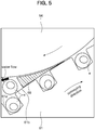
- the removing roller 64 in the water tank 8 water flow in a direction away from the guide member 63 is formed in the fish-egg feeding area 65 as illustrated in FIG. 5 .
- the grooves 64a on the outer peripheral surface of the removing roller 64 are not illustrated. Therefore, the water flow in the direction away from the guide member 63 prevents the fish egg e from moving to an area 66 where the peripheral part of the conveying gear 61 and the outer peripheral surface of the removing roller 64 are located close to each other, e.g., the wedge-shaped area 66 where the distance between the peripheral part of the conveying gear 61 and the outer peripheral surface of the removing roller 64 is smaller than the diameter of the fish egg e.
- the fish-egg conveying apparatus 6 is characterized by including: the water tank 8 into which the fish eggs e are introduced; the conveying gear 61 that rotates in the water tank 8 and includes the peripheral part provided with the plurality of housing recesses 61a housing each one of the fish eggs e; the guide member 63 disposed along a part of the peripheral part of the conveying gear 61 in the water tank 8; and the removing roller 64 that rotates on the upstream side of the guide member 63 in the water tank 8 in the rotation direction of the conveying gear 61, such that the part opposed to the peripheral part of the conveying gear 61 moves in a direction away from the guide member 63.
- the removing roller 64 rotates on the upstream side of the guide member 63 in the water tank 8 in the conveying direction (the upstream side in the rotation direction of the conveying gear 61), whereby water flow is formed in the area 65 where the fish egg e is supplied to the peripheral part of the conveying gear 61 in the water tank 8, and this prevents the fish egg e not housed in the housing recess 61a of the conveying gear 61 from moving to the area 66 where the peripheral part of the conveying gear 61 and the outer peripheral surface of the removing roller 64 are located close to each other.
- the fish egg e is brought into contact with the outer peripheral surface of the removing roller 64, whereby the fish egg e not housed in the housing recess 61a of the conveying gear 61 is prevented from moving to the area 66 where the peripheral part of the conveying gear 61 and the outer peripheral surface of the removing roller 64 are located close to each other.
- the fish egg e it is possible to prevent the fish egg e from being caught and crushed between the peripheral part of the conveying gear 61 and the guide member 63 when the fish egg e moves to the housing recess 61a of the conveying gear 61.
- the fish-egg conveying apparatus 6 is characterized in that projections and recesses are formed on the outer peripheral surface of the removing roller 64.
- water flow is easily formed in the water tank 8 as the removing roller 64 rotates. Further, by the fish egg e contacting the outer peripheral surface of the removing roller 64, the fish egg e easily moves in a direction away from the peripheral part of the conveying gear 61. Thus, the fish egg e can be effectively prevented from being caught and crushed between the peripheral part of the conveying gear 61 and the guide member 63.
- the fish-egg conveying apparatus 6 is characterized in that, on the outer peripheral surface of the removing roller 64, the plurality of grooves 64a extending along the thickness direction thereof are formed.
- the fish-egg conveying apparatus 6 is characterized in that the conveying gear 61 intermittently rotates so as to alternately repeat a rotating state and a stopped state, and the removing roller 64 continuously rotates.
- the removing roller 64 continuously rotates while the conveying gear 61 intermittently rotates, whereby the fish eggs e are each easily housed in the single housing recess 61a of the conveying gear 61 in the water tank 8.
- the fish-egg conveying apparatus 6 is characterized in that, when the conveying gear 61 is in the stopped state, the straight line passing through the rotation center of the conveying gear 61 and the rotation center of the removing roller 64 in a side view passes through a part of the peripheral part of the conveying gear 61 where the housing recess 61a is not provided.
- the area where the peripheral part of the conveying gear 61 and the outer peripheral surface of the removing roller 64 are located close to each other is a wedge-shaped area, whereby the water flow formed in the water tank 8 by the rotation of the removing roller 64 can effectively prevent the fish egg e not housed in the housing recess 61a of the conveying gear 61 from moving to the area 66 where the peripheral part of the conveying gear 61 and the outer peripheral surface of the removing roller 64 are located close to each other.
- the fish eggs e are conveyed by rotating the conveying gear 61 having the peripheral part provided with the plurality of housing recesses 61a for housing and conveying the fish eggs e in the water tank 8 into which the fish eggs e are introduced, and the removing roller 64 disposed close to the peripheral part of the conveying gear 61 is rotated at the rotation velocity corresponding to the rotation velocity of the conveying gear 61 such that the part A of the removing roller 64 opposed to the peripheral part of the conveying gear 61 moves in the direction opposite to the movement direction of the peripheral part of the conveying gear 61.
- the water flow formed in the water tank 8 by the rotation of the removing roller 64 can prevent the fish egg e from moving to the area 66 where the peripheral part of the conveying gear 61 and the outer peripheral surface of the removing roller 64 are located close to each other.
- the fish eggs e are conveyed by rotating the conveying gear 61 having the peripheral part provided with the plurality of housing recesses 61a for housing and conveying the fish eggs e, and water flow is formed in the direction opposite to the movement direction of the peripheral part of the conveying gear 61 by the removing roller 64 disposed close to the peripheral part of the conveying gear 61.
- water flow is formed in the direction opposite to the movement direction of the peripheral part of the conveying gear 61 in the area close to the peripheral part of the conveying gear 61 in the water tank 8, whereby the fish egg e not housed in the housing recess 61a of the conveying gear 61 is prevented from moving to the area where the peripheral part of the conveying gear 61 and the outer peripheral surface of the removing roller 64 are located close to each other.
- the soft spherical object in the present invention is not limited to the fish egg e, but it may be soft spherical objects other than the fish eggs e. Therefore, the soft spherical objects in the present invention may be soft spherical objects such as artificial salmon roes, and the present invention is applicable to a conveying apparatus that conveys the soft spherical objects and that is configured to possibly allow the soft spherical objects to be caught and crushed between the peripheral part of the conveying gear and the guide member.
- the outer peripheral surface of the removing roller 64 may not be provided with protrusions and recesses. Furthermore, although the case where the plurality of grooves 64a extending along the thickness direction of the removing roller 64 are formed on the outer peripheral surface of the removing roller 64 as the projections and recesses is explained in the above embodiment, the configuration of the protrusions and the recesses formed on the outer peripheral surface of the removing roller 64 is not limited thereto.
- the removing roller 64 may intermittently rotate. Further, instead of rotating at a constant rotation velocity, the rotation velocity of the removing roller 64 may be changed. Therefore, the rotation velocity of the removing roller 64 may be changed depending on the size, specific gravity, and elasticity of the soft spherical object (e. g., fish egg).
- the conveying gear 61 intermittently rotates, and when the conveying gear 61 is in the stopped state, the straight line passing through the rotation center of the conveying gear 61 and the rotation center of the removing roller 64 in a side view passes through the part of the peripheral part of the conveying gear 61 where the housing recess 61a is not provided; however, the straight line passing through the rotation center of the conveying gear 61 and the rotation center of the removing roller 64 in a side view may pass through the part of the peripheral part of the conveying gear 61 where the housing recess 61a is provided.
- the gene injection system automated microinjection apparatus
- the fish-egg conveying apparatus 6 is applicable to, for example, an apparatus for checking and selecting gene expression of an egg by using a fluorescent microscope or the like.
- the fish-egg conveying apparatus that conveys fish eggs having a specific gravity larger than the specific gravity of the solvent (e.g., water) in the water tank 8
- the fish-egg conveying apparatus may convey fish eggs having a specific gravity smaller than the specific gravity of a solvent (e.g., seawater) in the water tank 8.
- a solvent e.g., seawater
- the conveying gear 61 having the housing recesses 61a on the peripheral part thereof is used as a conveying rotary member that conveys fish eggs one by one
- the conveying rotary member that conveys fish eggs one by one is not limited to the conveying gear 61.
- the conveying rotary member that conveys fish eggs one by one may have, for example, a belt-like shape or a chain-like shape capable of forming an endless track, as long as the shape makes it possible to convey fish eggs one by one.
- the removing roller 64 is disposed, as a removing unit, in the area close to the peripheral part of the conveying gear 61 in the water tank 8 and water flow is formed in the direction opposite to the movement direction of the peripheral part of the conveying gear 61 by rotating the removing roller 64; however, the configuration of the removing unit for forming water flow in the direction opposite to the movement direction of the peripheral part of the conveying gear 61 in the area close to the peripheral part of the conveying gear 61 is not limited to the removing roller 64.
- an ejection unit that ejects water in the direction opposite to the movement direction of the peripheral part of the conveying gear 61 may be disposed, as a removing unit, in the area close to the peripheral part of the conveying gear 61, and water flow may be formed in the direction opposite to the movement direction of the peripheral part of the conveying gear 61 by ejecting water from the ejection unit.
- a fish-egg conveying apparatus includes: a water tank 8 into which at least one fish egg is introduced; a conveying gear 61 that rotates in the water tank 8 and has a peripheral part provided with a plurality of housing recesses housing each one of the fish eggs; a guide member 63 disposed along part of the peripheral part of the conveying gear 61 in the water tank 8; and a removing roller 64 that rotates on an upstream side of the guide member 63 in the water tank 8 in a rotation direction of the conveying gear 61, such that a part of the removing roller 64 opposed to the peripheral part of the conveying gear 61 moves in a direction away from the guide member 63.
Landscapes
- Life Sciences & Earth Sciences (AREA)
- Mechanical Engineering (AREA)
- Engineering & Computer Science (AREA)
- Environmental Sciences (AREA)
- Fluid Mechanics (AREA)
- Physics & Mathematics (AREA)
- Marine Sciences & Fisheries (AREA)
- Zoology (AREA)
- Animal Husbandry (AREA)
- Biodiversity & Conservation Biology (AREA)
- Farming Of Fish And Shellfish (AREA)
- Apparatus Associated With Microorganisms And Enzymes (AREA)
- Micro-Organisms Or Cultivation Processes Thereof (AREA)
- Meat, Egg Or Seafood Products (AREA)
Applications Claiming Priority (1)
| Application Number | Priority Date | Filing Date | Title |
|---|---|---|---|
| JP2018140549A JP7111963B2 (ja) | 2018-07-26 | 2018-07-26 | 魚卵搬送装置及び魚卵の搬送方法 |
Publications (1)
| Publication Number | Publication Date |
|---|---|
| EP3598894A1 true EP3598894A1 (fr) | 2020-01-29 |
Family
ID=67438484
Family Applications (1)
| Application Number | Title | Priority Date | Filing Date |
|---|---|---|---|
| EP19187712.5A Withdrawn EP3598894A1 (fr) | 2018-07-26 | 2019-07-23 | Appareil et procédé de transport d'objets sphériques souples |
Country Status (3)
| Country | Link |
|---|---|
| US (1) | US20200071092A1 (fr) |
| EP (1) | EP3598894A1 (fr) |
| JP (1) | JP7111963B2 (fr) |
Cited By (1)
| Publication number | Priority date | Publication date | Assignee | Title |
|---|---|---|---|---|
| IT202100012215A1 (it) * | 2021-05-12 | 2022-11-12 | T T C S R L S | Selezionatore per uova di pesce per la selezione e il conteggio delle uova |
Citations (6)
| Publication number | Priority date | Publication date | Assignee | Title |
|---|---|---|---|---|
| US3613884A (en) * | 1970-04-13 | 1971-10-19 | Neil Van Gaalen | Fish egg sorting apparatus |
| JPS5647005B2 (fr) | 1976-05-25 | 1981-11-06 | ||
| JPS5823112B2 (ja) | 1975-05-09 | 1983-05-13 | クラレンス ケイ エドワ−ズ | モケイテツドウソウチ |
| JPS63287411A (ja) * | 1987-05-20 | 1988-11-24 | Suzutec Co Ltd | 育苗箱用播種装置の繰出ロ−ル |
| JP5787432B2 (ja) | 2010-10-19 | 2015-09-30 | 橋本電子工業株式会社 | 多数の魚卵を処理する方法 |
| WO2016051994A1 (fr) * | 2014-09-29 | 2016-04-07 | アグリテクノ矢崎株式会社 | Dispositif d'alimentation |
Family Cites Families (4)
| Publication number | Priority date | Publication date | Assignee | Title |
|---|---|---|---|---|
| US3575280A (en) * | 1968-12-16 | 1971-04-20 | Denny B Mcclary | Fish egg counter |
| US5531312A (en) * | 1994-10-24 | 1996-07-02 | Dickey; Daniel M. | Apparatus and method for singulating articles |
| EP1166633A1 (fr) * | 2000-06-27 | 2002-01-02 | Kraft Foods R&D, Inc. | Dispositif pour déposer des produits alimentaires granulaires sur des éléments en mouvement |
| US20120178646A1 (en) | 2009-07-08 | 2012-07-12 | Zf Screens B.V. | High throughput method and system for in vivo screening |
-
2018
- 2018-07-26 JP JP2018140549A patent/JP7111963B2/ja active Active
-
2019
- 2019-07-23 EP EP19187712.5A patent/EP3598894A1/fr not_active Withdrawn
- 2019-07-24 US US16/521,010 patent/US20200071092A1/en not_active Abandoned
Patent Citations (6)
| Publication number | Priority date | Publication date | Assignee | Title |
|---|---|---|---|---|
| US3613884A (en) * | 1970-04-13 | 1971-10-19 | Neil Van Gaalen | Fish egg sorting apparatus |
| JPS5823112B2 (ja) | 1975-05-09 | 1983-05-13 | クラレンス ケイ エドワ−ズ | モケイテツドウソウチ |
| JPS5647005B2 (fr) | 1976-05-25 | 1981-11-06 | ||
| JPS63287411A (ja) * | 1987-05-20 | 1988-11-24 | Suzutec Co Ltd | 育苗箱用播種装置の繰出ロ−ル |
| JP5787432B2 (ja) | 2010-10-19 | 2015-09-30 | 橋本電子工業株式会社 | 多数の魚卵を処理する方法 |
| WO2016051994A1 (fr) * | 2014-09-29 | 2016-04-07 | アグリテクノ矢崎株式会社 | Dispositif d'alimentation |
Cited By (2)
| Publication number | Priority date | Publication date | Assignee | Title |
|---|---|---|---|---|
| IT202100012215A1 (it) * | 2021-05-12 | 2022-11-12 | T T C S R L S | Selezionatore per uova di pesce per la selezione e il conteggio delle uova |
| EP4088571A1 (fr) * | 2021-05-12 | 2022-11-16 | T.T.C. S.r.l.s. | Trieuse d'oeufs de poisson pour sélectionner et compter les oeufs |
Also Published As
| Publication number | Publication date |
|---|---|
| JP7111963B2 (ja) | 2022-08-03 |
| US20200071092A1 (en) | 2020-03-05 |
| JP2020014426A (ja) | 2020-01-30 |
Similar Documents
| Publication | Publication Date | Title |
|---|---|---|
| EP3696257A1 (fr) | Appareil de traitement d'oeufs de poisson | |
| Wang et al. | High-throughput automated injection of individual biological cells | |
| US8470267B2 (en) | Apparatus for separating magnetic particles from liquids containing said particles, and an array of vessels suitable for use with such an apparatus | |
| DE69808272T2 (de) | Reaktion behälter apparat | |
| Baas et al. | Slow axonal transport and the genesis of neuronal morphology | |
| DE07020151T1 (de) | Vorrichtung und Verfahren zur Aufnahme von Tierzellenkolonien | |
| EP3598894A1 (fr) | Appareil et procédé de transport d'objets sphériques souples | |
| EP3746382B1 (fr) | Système de fourniture d'échantillons | |
| CN103358111B (zh) | 一种采血针中阻血套的自动组装方法及其装置 | |
| WO2019012973A1 (fr) | Système de traitement d'œufs | |
| CN105792645B (zh) | 用于使格槽式托盘内的蛋重新定向的设备 | |
| Stepicheva et al. | High throughput microinjections of sea urchin zygotes | |
| US20200224237A1 (en) | Soft sphere transfer device and recombinant protein production method | |
| CN107345199A (zh) | 生物样品制备系统 | |
| EP1582593B1 (fr) | Appareil et puce pour l'injection d'une substance dans une particule | |
| WO2005065831A1 (fr) | Separation et purification d'une suspension a l'aide de microparticules magnetiques | |
| JP2006034174A (ja) | インジェクション装置 | |
| DE202012001250U1 (de) | Renester zur automatischen Bestückung von Spritzennestern mit Fertigspritzen | |
| EP3653694A1 (fr) | Dispositif de traitement d'oeufs de poisson | |
| JP4555650B2 (ja) | 細胞給排・捕捉装置及び細胞給排・捕捉方法 | |
| US20100300547A1 (en) | Object-holding sheet, test method and object-treating equipment | |
| JP7511315B2 (ja) | 魚卵処理装置 | |
| JP2005027626A (ja) | 試料注入装置及び試料注入方法 | |
| Xu et al. | Mosquito staging apparatus for producing PfSPZ malaria vaccines | |
| JPH07833A (ja) | マイクロピペット用チップのラック挿入方法 |
Legal Events
| Date | Code | Title | Description |
|---|---|---|---|
| PUAI | Public reference made under article 153(3) epc to a published international application that has entered the european phase |
Free format text: ORIGINAL CODE: 0009012 |
|
| AK | Designated contracting states |
Kind code of ref document: A1 Designated state(s): AL AT BE BG CH CY CZ DE DK EE ES FI FR GB GR HR HU IE IS IT LI LT LU LV MC MK MT NL NO PL PT RO RS SE SI SK SM TR |
|
| AX | Request for extension of the european patent |
Extension state: BA ME |
|
| STAA | Information on the status of an ep patent application or granted ep patent |
Free format text: STATUS: THE APPLICATION IS DEEMED TO BE WITHDRAWN |
|
| 18D | Application deemed to be withdrawn |
Effective date: 20200730 |