EP3599083A1 - Kontinuierliche herstellung für verbundwerkstoffvorformen - Google Patents
Kontinuierliche herstellung für verbundwerkstoffvorformen Download PDFInfo
- Publication number
- EP3599083A1 EP3599083A1 EP19172794.0A EP19172794A EP3599083A1 EP 3599083 A1 EP3599083 A1 EP 3599083A1 EP 19172794 A EP19172794 A EP 19172794A EP 3599083 A1 EP3599083 A1 EP 3599083A1
- Authority
- EP
- European Patent Office
- Prior art keywords
- web
- tow
- preform
- roller
- fiber reinforced
- Prior art date
- Legal status (The legal status is an assumption and is not a legal conclusion. Google has not performed a legal analysis and makes no representation as to the accuracy of the status listed.)
- Granted
Links
Images




Classifications
-
- B—PERFORMING OPERATIONS; TRANSPORTING
- B29—WORKING OF PLASTICS; WORKING OF SUBSTANCES IN A PLASTIC STATE IN GENERAL
- B29B—PREPARATION OR PRETREATMENT OF THE MATERIAL TO BE SHAPED; MAKING GRANULES OR PREFORMS; RECOVERY OF PLASTICS OR OTHER CONSTITUENTS OF WASTE MATERIAL CONTAINING PLASTICS
- B29B11/00—Making preforms
- B29B11/06—Making preforms by moulding the material
- B29B11/12—Compression moulding
-
- B—PERFORMING OPERATIONS; TRANSPORTING
- B29—WORKING OF PLASTICS; WORKING OF SUBSTANCES IN A PLASTIC STATE IN GENERAL
- B29C—SHAPING OR JOINING OF PLASTICS; SHAPING OF MATERIAL IN A PLASTIC STATE, NOT OTHERWISE PROVIDED FOR; AFTER-TREATMENT OF THE SHAPED PRODUCTS, e.g. REPAIRING
- B29C70/00—Shaping composites, i.e. plastics material comprising reinforcements, fillers or preformed parts, e.g. inserts
- B29C70/04—Shaping composites, i.e. plastics material comprising reinforcements, fillers or preformed parts, e.g. inserts comprising reinforcements only, e.g. self-reinforcing plastics
- B29C70/28—Shaping operations therefor
- B29C70/30—Shaping by lay-up, i.e. applying fibres, tape or broadsheet on a mould, former or core; Shaping by spray-up, i.e. spraying of fibres on a mould, former or core
- B29C70/38—Automated lay-up, e.g. using robots, laying filaments according to predetermined patterns
-
- B—PERFORMING OPERATIONS; TRANSPORTING
- B26—HAND CUTTING TOOLS; CUTTING; SEVERING
- B26D—CUTTING; DETAILS COMMON TO MACHINES FOR PERFORATING, PUNCHING, CUTTING-OUT, STAMPING-OUT OR SEVERING
- B26D7/00—Details of apparatus for cutting, cutting-out, stamping-out, punching, perforating, or severing by means other than cutting
- B26D7/08—Means for treating work or cutting member to facilitate cutting
- B26D7/14—Means for treating work or cutting member to facilitate cutting by tensioning the work
-
- B—PERFORMING OPERATIONS; TRANSPORTING
- B26—HAND CUTTING TOOLS; CUTTING; SEVERING
- B26F—PERFORATING; PUNCHING; CUTTING-OUT; STAMPING-OUT; SEVERING BY MEANS OTHER THAN CUTTING
- B26F1/00—Perforating; Punching; Cutting-out; Stamping-out; Apparatus therefor
- B26F1/38—Cutting-out; Stamping-out
- B26F1/40—Cutting-out; Stamping-out using a press, e.g. of the ram type
-
- B—PERFORMING OPERATIONS; TRANSPORTING
- B29—WORKING OF PLASTICS; WORKING OF SUBSTANCES IN A PLASTIC STATE IN GENERAL
- B29B—PREPARATION OR PRETREATMENT OF THE MATERIAL TO BE SHAPED; MAKING GRANULES OR PREFORMS; RECOVERY OF PLASTICS OR OTHER CONSTITUENTS OF WASTE MATERIAL CONTAINING PLASTICS
- B29B11/00—Making preforms
- B29B11/02—Making preforms by dividing preformed material, e.g. sheets, rods
-
- B—PERFORMING OPERATIONS; TRANSPORTING
- B29—WORKING OF PLASTICS; WORKING OF SUBSTANCES IN A PLASTIC STATE IN GENERAL
- B29B—PREPARATION OR PRETREATMENT OF THE MATERIAL TO BE SHAPED; MAKING GRANULES OR PREFORMS; RECOVERY OF PLASTICS OR OTHER CONSTITUENTS OF WASTE MATERIAL CONTAINING PLASTICS
- B29B11/00—Making preforms
- B29B11/14—Making preforms characterised by structure or composition
- B29B11/16—Making preforms characterised by structure or composition comprising fillers or reinforcement
-
- B—PERFORMING OPERATIONS; TRANSPORTING
- B29—WORKING OF PLASTICS; WORKING OF SUBSTANCES IN A PLASTIC STATE IN GENERAL
- B29C—SHAPING OR JOINING OF PLASTICS; SHAPING OF MATERIAL IN A PLASTIC STATE, NOT OTHERWISE PROVIDED FOR; AFTER-TREATMENT OF THE SHAPED PRODUCTS, e.g. REPAIRING
- B29C70/00—Shaping composites, i.e. plastics material comprising reinforcements, fillers or preformed parts, e.g. inserts
- B29C70/04—Shaping composites, i.e. plastics material comprising reinforcements, fillers or preformed parts, e.g. inserts comprising reinforcements only, e.g. self-reinforcing plastics
- B29C70/06—Fibrous reinforcements only
- B29C70/10—Fibrous reinforcements only characterised by the structure of fibrous reinforcements, e.g. hollow fibres
- B29C70/16—Fibrous reinforcements only characterised by the structure of fibrous reinforcements, e.g. hollow fibres using fibres of substantial or continuous length
- B29C70/20—Fibrous reinforcements only characterised by the structure of fibrous reinforcements, e.g. hollow fibres using fibres of substantial or continuous length oriented in a single direction, e.g. roofing or other parallel fibres
- B29C70/202—Fibrous reinforcements only characterised by the structure of fibrous reinforcements, e.g. hollow fibres using fibres of substantial or continuous length oriented in a single direction, e.g. roofing or other parallel fibres arranged in parallel planes or structures of fibres crossing at substantial angles, e.g. cross-moulding compound [XMC]
-
- B—PERFORMING OPERATIONS; TRANSPORTING
- B29—WORKING OF PLASTICS; WORKING OF SUBSTANCES IN A PLASTIC STATE IN GENERAL
- B29C—SHAPING OR JOINING OF PLASTICS; SHAPING OF MATERIAL IN A PLASTIC STATE, NOT OTHERWISE PROVIDED FOR; AFTER-TREATMENT OF THE SHAPED PRODUCTS, e.g. REPAIRING
- B29C70/00—Shaping composites, i.e. plastics material comprising reinforcements, fillers or preformed parts, e.g. inserts
- B29C70/04—Shaping composites, i.e. plastics material comprising reinforcements, fillers or preformed parts, e.g. inserts comprising reinforcements only, e.g. self-reinforcing plastics
- B29C70/28—Shaping operations therefor
- B29C70/30—Shaping by lay-up, i.e. applying fibres, tape or broadsheet on a mould, former or core; Shaping by spray-up, i.e. spraying of fibres on a mould, former or core
- B29C70/38—Automated lay-up, e.g. using robots, laying filaments according to predetermined patterns
- B29C70/386—Automated tape laying [ATL]
-
- B—PERFORMING OPERATIONS; TRANSPORTING
- B29—WORKING OF PLASTICS; WORKING OF SUBSTANCES IN A PLASTIC STATE IN GENERAL
- B29C—SHAPING OR JOINING OF PLASTICS; SHAPING OF MATERIAL IN A PLASTIC STATE, NOT OTHERWISE PROVIDED FOR; AFTER-TREATMENT OF THE SHAPED PRODUCTS, e.g. REPAIRING
- B29C70/00—Shaping composites, i.e. plastics material comprising reinforcements, fillers or preformed parts, e.g. inserts
- B29C70/04—Shaping composites, i.e. plastics material comprising reinforcements, fillers or preformed parts, e.g. inserts comprising reinforcements only, e.g. self-reinforcing plastics
- B29C70/28—Shaping operations therefor
- B29C70/40—Shaping or impregnating by compression not applied
- B29C70/42—Shaping or impregnating by compression not applied for producing articles of definite length, i.e. discrete articles
- B29C70/46—Shaping or impregnating by compression not applied for producing articles of definite length, i.e. discrete articles using matched moulds, e.g. for deforming sheet moulding compounds [SMC] or prepregs
-
- B—PERFORMING OPERATIONS; TRANSPORTING
- B29—WORKING OF PLASTICS; WORKING OF SUBSTANCES IN A PLASTIC STATE IN GENERAL
- B29C—SHAPING OR JOINING OF PLASTICS; SHAPING OF MATERIAL IN A PLASTIC STATE, NOT OTHERWISE PROVIDED FOR; AFTER-TREATMENT OF THE SHAPED PRODUCTS, e.g. REPAIRING
- B29C70/00—Shaping composites, i.e. plastics material comprising reinforcements, fillers or preformed parts, e.g. inserts
- B29C70/04—Shaping composites, i.e. plastics material comprising reinforcements, fillers or preformed parts, e.g. inserts comprising reinforcements only, e.g. self-reinforcing plastics
- B29C70/28—Shaping operations therefor
- B29C70/54—Component parts, details or accessories; Auxiliary operations, e.g. feeding or storage of prepregs or SMC after impregnation or during ageing
- B29C70/545—Perforating, cutting or machining during or after moulding
-
- B—PERFORMING OPERATIONS; TRANSPORTING
- B32—LAYERED PRODUCTS
- B32B—LAYERED PRODUCTS, i.e. PRODUCTS BUILT-UP OF STRATA OF FLAT OR NON-FLAT, e.g. CELLULAR OR HONEYCOMB, FORM
- B32B37/00—Methods or apparatus for laminating, e.g. by curing or by ultrasonic bonding
- B32B37/14—Methods or apparatus for laminating, e.g. by curing or by ultrasonic bonding characterised by the properties of the layers
- B32B37/16—Methods or apparatus for laminating, e.g. by curing or by ultrasonic bonding characterised by the properties of the layers with all layers existing as coherent layers before laminating
- B32B37/22—Methods or apparatus for laminating, e.g. by curing or by ultrasonic bonding characterised by the properties of the layers with all layers existing as coherent layers before laminating involving the assembly of both discrete and continuous layers
-
- B—PERFORMING OPERATIONS; TRANSPORTING
- B65—CONVEYING; PACKING; STORING; HANDLING THIN OR FILAMENTARY MATERIAL
- B65H—HANDLING THIN OR FILAMENTARY MATERIAL, e.g. SHEETS, WEBS, CABLES
- B65H16/00—Unwinding, paying-out webs
- B65H16/10—Arrangements for effecting positive rotation of web roll
-
- B—PERFORMING OPERATIONS; TRANSPORTING
- B26—HAND CUTTING TOOLS; CUTTING; SEVERING
- B26F—PERFORATING; PUNCHING; CUTTING-OUT; STAMPING-OUT; SEVERING BY MEANS OTHER THAN CUTTING
- B26F2210/00—Perforating, punching, cutting-out, stamping-out, severing by means other than cutting of specific products
- B26F2210/12—Perforating, punching, cutting-out, stamping-out, severing by means other than cutting of specific products of fabrics
- B26F2210/16—Perforating, punching, cutting-out, stamping-out, severing by means other than cutting of specific products of fabrics the cutting machine comprising a cutting die
-
- B—PERFORMING OPERATIONS; TRANSPORTING
- B29—WORKING OF PLASTICS; WORKING OF SUBSTANCES IN A PLASTIC STATE IN GENERAL
- B29C—SHAPING OR JOINING OF PLASTICS; SHAPING OF MATERIAL IN A PLASTIC STATE, NOT OTHERWISE PROVIDED FOR; AFTER-TREATMENT OF THE SHAPED PRODUCTS, e.g. REPAIRING
- B29C2793/00—Shaping techniques involving a cutting or machining operation
- B29C2793/0009—Cutting out
-
- B—PERFORMING OPERATIONS; TRANSPORTING
- B29—WORKING OF PLASTICS; WORKING OF SUBSTANCES IN A PLASTIC STATE IN GENERAL
- B29C—SHAPING OR JOINING OF PLASTICS; SHAPING OF MATERIAL IN A PLASTIC STATE, NOT OTHERWISE PROVIDED FOR; AFTER-TREATMENT OF THE SHAPED PRODUCTS, e.g. REPAIRING
- B29C2793/00—Shaping techniques involving a cutting or machining operation
- B29C2793/0081—Shaping techniques involving a cutting or machining operation before shaping
-
- B—PERFORMING OPERATIONS; TRANSPORTING
- B29—WORKING OF PLASTICS; WORKING OF SUBSTANCES IN A PLASTIC STATE IN GENERAL
- B29C—SHAPING OR JOINING OF PLASTICS; SHAPING OF MATERIAL IN A PLASTIC STATE, NOT OTHERWISE PROVIDED FOR; AFTER-TREATMENT OF THE SHAPED PRODUCTS, e.g. REPAIRING
- B29C2793/00—Shaping techniques involving a cutting or machining operation
- B29C2793/009—Shaping techniques involving a cutting or machining operation after shaping
-
- B—PERFORMING OPERATIONS; TRANSPORTING
- B29—WORKING OF PLASTICS; WORKING OF SUBSTANCES IN A PLASTIC STATE IN GENERAL
- B29K—INDEXING SCHEME ASSOCIATED WITH SUBCLASSES B29B, B29C OR B29D, RELATING TO MOULDING MATERIALS OR TO MATERIALS FOR MOULDS, REINFORCEMENTS, FILLERS OR PREFORMED PARTS, e.g. INSERTS
- B29K2307/00—Use of elements other than metals as reinforcement
- B29K2307/04—Carbon
-
- B—PERFORMING OPERATIONS; TRANSPORTING
- B29—WORKING OF PLASTICS; WORKING OF SUBSTANCES IN A PLASTIC STATE IN GENERAL
- B29L—INDEXING SCHEME ASSOCIATED WITH SUBCLASS B29C, RELATING TO PARTICULAR ARTICLES
- B29L2031/00—Other particular articles
- B29L2031/30—Vehicles, e.g. ships or aircraft, or body parts thereof
- B29L2031/3076—Aircrafts
-
- B—PERFORMING OPERATIONS; TRANSPORTING
- B65—CONVEYING; PACKING; STORING; HANDLING THIN OR FILAMENTARY MATERIAL
- B65H—HANDLING THIN OR FILAMENTARY MATERIAL, e.g. SHEETS, WEBS, CABLES
- B65H2701/00—Handled material; Storage means
- B65H2701/10—Handled articles or webs
- B65H2701/17—Nature of material
- B65H2701/174—Textile; fibres
Definitions
- the disclosure relates to the field of composite parts, and in particular, to laying up preforms for composite parts.
- layup a preform that will be hardened into a composite part remains a labor intensive process.
- plies of fiber reinforced material are iteratively applied over a layup tool, such as a mandrel.
- a robot such as an Automated Fiber Placement (AFP) machine may be used to facilitate the layup process.
- Layup continues until the preform achieves a desired shape.
- the preform may then be transferred to a forming tool and shaped before it is hardened into a composite part.
- individual plies that will form part of the preform may be cut and stored.
- Ply storage may occupy a large amount of space in the fabrication environment, and may even utilize specialized temperature or humidity controlled storage chambers. Furthermore, transfer of a preform from a layup tool to a forming tool may distort portions of the preform, which is undesirable.
- Embodiments described herein provide continuous fabrication techniques for generating preforms that do not necessitate storage of pre-cut plies, nor transfer of a preform from a layup tool to a forming tool. These continuous techniques may also eliminate the need for expensive equipment such as AFP machines, and may accelerate the process by which preforms are fabricated.
- One embodiment is a method of creating a preform.
- the method includes conveying a web of fiber reinforced composite material in a process direction, disposing fiber reinforced composite material atop the web, conveying the web and the tow in the process direction to a cutting tool, and cutting out a preform comprising a combination of the tow and the web.
- a further embodiment is a non-transitory computer readable medium embodying programmed instructions which, when executed by a processor, are operable for performing a method for creating a preform.
- the method includes conveying a web of fiber reinforced composite material in a process direction, disposing fiber reinforced composite material atop the web, conveying the web and the tow in the process direction to a cutting tool, and cutting out a preform comprising a combination of the tow and the web.
- the apparatus includes a web advancement mechanism that conveys a web of fiber reinforced composite material in a process direction, at least one deposition station that disposes fiber reinforced composite material atop the web; and a cutting tool disposed downstream of the deposition station that cuts out a preform comprising a combination of the tow and the web.
- CFRP Carbon Fiber Reinforced Polymer
- CFRP Carbon Fiber Reinforced Polymer
- the preform may include a resin that solidifies in order to harden the preform into a composite part (e.g., for use in an aircraft).
- CFRP Carbon Fiber Reinforced Polymer
- Carbon fiber that has been impregnated with an uncured thermoset resin or a thermoplastic resin is referred to as "prepreg.”
- Other types of carbon fiber include "dry fiber” which has not been impregnated with thermoset resin but may include a tackifier or binder. Dry fiber may be infused with resin prior to curing.
- the hardening is a one-way process referred to as curing, while for thermoplastic resins, the resin may return to liquid form if it is re-heated.
- FIG. 1 is a perspective view of a preform fabrication system 100 in an illustrative embodiment.
- Preform fabrication system 100 comprises any system, device, or component operable to lay up tows of fiber reinforced material onto a web of fiber reinforced material, and to cut the tows and web into a preform for hardening into a composite part.
- preform fabrication system 100 includes dispensing spool 110, which may be mechanically driven to dispense web 120 of fiber reinforced material (e.g., CFRP, such as unidirectional CFRP having a fiber orientation of 0° +45°, -45°, 90° , or even a web of woven material or non-woven material) continuously in a process direction at several to many feet per second.
- the fiber reinforced material may comprise any suitable material, including dry fiber, pre-preg, etc.
- One or more ply deposition stations may dispose tows onto surface 122 of web 120.
- angled deposition stations 140 may dispense tows 142 that are angled (e.g., + ⁇ °, - ⁇ °) with respect to the process direction
- perpendicular deposition station 150 may dispense tows 152 that are perpendicular to the process direction.
- the ply deposition stations may operate even while web 120 is traveling in the process direction in order to enhance fabrication speed, and may dispense tows 142 at a rate slower than, equal to, or faster than the speed of web 120.
- Conveyor 130 may contact surface 124 of web 120, and prevents web 120 from deflecting downward (i.e., in the negative Y direction) when tows are applied to web 120. Stated more directly, conveyor 130 provides a reaction to any compaction force applied during tow deposition. This enables tows to be adhered to web 120 via the application of pressure against web 120. In such instances, both tows and web 120 may include a tackifier or binder that facilitates adherence of the tows to the web 120.
- Forming station 160 includes stamp 162 and mandrel 164.
- stamp 162 When stamp 162 is driven into mandrel 164, stamp 162 applies forces which form the web 120 into a predetermined shape. While web 120 is shaped in this manner, cutting tool 166 (e.g., a tool having a circumferential blade 167 of FIG. 3 that cuts an entire preform from web 120 at once, or a traveling blade that cuts a portion of web 120 at a time) cuts out the shaped portion of the web, resulting in a preform.
- cutting tool 166 e.g., a tool having a circumferential blade 167 of FIG. 3 that cuts an entire preform from web 120 at once, or a traveling blade that cuts a portion of web 120 at a time
- the preform may then be removed from stamp 162 or mandrel 164, and a new section of web 120 may be conveyed into forming station 160. Unused portions of web 120 may be acquired by take-up spool 170, which may also be mechanically driven (e.g., by an internal actuator) in order to provide take up portions of web 120.
- the driving of dispensing spool 110 and take-up spool 170 may be coordinated to apply tension to web 120 during the creation of preforms and/or the application of tows to web 120.
- preform fabrication system 100 By fabricating preforms as part of a continuous process, preform fabrication system 100 avoids numerous issues that were encountered by prior systems. For example, preform fabrication system 100 does not require storage of pre-cut plies, does not require the use of expensive AFP machines, and also does not require layup processes to be separated from cutting processes. Still further, preform fabrication system 100 does not require complex and expensive lay-up mandrels (e.g., with or without contours), and does not require lay-up controls to compensate for laying up upon a mandrel (e.g., especially contoured and/or complex contoured mandrels). These advantages enable preforms to be created in a manner that is both faster and less expensive than prior systems could achieve.
- preform fabrication system 100 Illustrative details of the operation of preform fabrication system 100 will be discussed with regard to FIG. 2 . Assume, for this embodiment, that dispensing spool 110 is loaded with web 120, and that a technician wishes to initiate fabrication of preforms at web 120. The technician draws web 120 to the take-up spool 170, and proceeds to direct dispensing spool 110 and take-up spool 170 to start spinning.
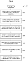
- FIG. 2 is a flowchart illustrating a method 200 for operating a preform fabrication system in an illustrative embodiment.
- the steps of method 200 are described with reference to preform fabrication system 100 of FIG. 1 , but those skilled in the art will appreciate that method 200 may be performed in other systems.
- the steps of the flowcharts described herein are not all inclusive and may include other steps not shown. The steps described herein may also be performed in an alternative order.
- dispensing spool 110 and take-up spool 170 convey the web 120 in the process direction. This may be performed at a constant velocity in order to advance a portion of web 120 towards the angled deposition stations 140. As web 120 is conveyed, dispensing spool 110 continues to provide new portions of the web 120.
- At least one tow of fiber reinforced composite material is disposed atop web 120.
- Tows may be placed by angled deposition stations 140, perpendicular deposition station 150, etc.
- Disposing a tow may comprise operating a roller (e.g., a roller 346 of FIG. 3 ) to dispense a tow 142 at a compaction force while conveyor 130 provides a reactionary force to the compaction force at the location of dispensing. This operation dispenses the tow 142 onto the web 120 (as illustrated in FIGS. 3-4 ).
- the tows may be placed while web 120 is temporarily paused.
- the tows may be dispensed while web 120 continues moving (i.e., being conveyed) in the process direction, by adjusting a position and/or orientation of the deposition stations in relation to web 120.
- the perpendicular deposition station 150 may move with web 120 in the process direction. Therefore, when viewed from the perspective of web 120, only the angled deposition stations 140 move at a different rate than web 120 in the process direction.
- a deposition station may adjust a position of a roller, an angle of a roller, or a combination of both as web 120 proceeds in the process direction and the roller dispenses a tow onto the web 120.
- a roller may for example be moved at a rate of speed of web 120 in the process direction, in order to remain unmoving with respect to web 120 along the process direction while dispensing a tow onto the web 120.
- multiple layers of tows may be placed atop one another, and the tows may be adhered to web 120 via the application of heat (e.g., one hundred and fifty degrees Fahrenheit) and/or pressure (e.g., a few hundred kilopascals) from one or more rollers at the deposition stations.
- heat e.g., one hundred and fifty degrees Fahrenheit
- pressure e.g., a few hundred kilopascals
- a series of angled deposition stations 140 and perpendicular deposition stations 150 may be placed at the underside of web 120, in order to replace conveyor 130 and provide a reactionary force.
- deposition stations may be placed further along the process direction and may encounter reaction forces applied by a conveyor located at surface 122 of web 120. The application of heat and/or pressure by a deposition station may enhance an amount of tack found in a binder at a dry fiber tow, and firmly adheres the tow to web 120. In this manner, disposing the tow atop the web adheres the tow to the web.
- the tows dispensed in step 204 need not be dispensed parallel with the process direction, and the tows may even have lengthwise axes that are not parallel with the process direction.
- the tows may comprise a ply of unidirectional fibers having a fiber orientation (e.g., 0° , +45°, -45°, 90°, or any angle ⁇ ) that is different than a fiber orientation of web 120.
- dispensing spool 110 and take-up spool 170 proceed to convey the web 120 and the at least one tow in the process direction in step 206. Since the tow is adhered to the web 120, conveying the web 120 in the process direction causes the web 120 to convey the tow in the process direction to forming station 160.
- Forming station 160 is depicted in FIG. 6 to provide stamp forming.
- step 208 forming station 160 operates stamp 162 and mandrel 164 to shape the combination of tow and web into a desired shape. This induces slippage between plies within the stamped tow and web in step 210. Hence, during the stamp forming process, plies may experience slippage (i.e., shear) relative to other plies. The process of stamp forming also consolidates plies within the stamped tow and web in step 212 after forming and slippage occurs.
- cutting tool 166 is operated to cut out a preform comprising the shaped combination of the tow and web.
- the web 120 may be temporarily halted at forming station 160 during this process, or the cutting and forming processes may be performed so quickly relative to the speed of conveyor 130 (e.g., within a fraction of a second) that no pause is required.
- the preform may then be moved to a curing tool, may be impregnated with resin, and may be hardened into a composite part.
- Method 200 provides a substantial benefit over prior techniques because it eliminates the need for pre-cutting of plies, eliminates the need for ply storage, and eliminates the need for AFP machines. This in turn reduces cost and increases throughput when fabricating composite parts, which is highly desirable.
- FIGS. 3-6 illustrate various features of preform fabrication system 100.
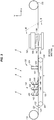
- FIG. 3 is a side view of preform fabrication system 100 in an illustrative embodiment.
- FIG. 3 illustrates that each angled deposition station 140 includes one or more spools 344 that supply the tows 142 to rollers 346.
- Each roller 346 may be heated and/or may be driven (e.g., while moving in the process direction or relative to the process direction) in order to dispense a tow 142 at a desired rate of speed onto the web 120. That is, the roller 346 dispenses a tow 142 at a rate relative to a speed of the web 120, and applies the tow 142 relative to the web 120 while the web 120 is moving.
- a roller 346 may press tow 142 against web 120 (and therefore press web 120 against belt 332 of conveyor 130) at a desired level of pressure, in order to tack a tow 142 to web 120.
- perpendicular deposition station 150 includes a spool 354 that supplies a tow 152 to a roller 356. Spool 354 may operate in a similar manner to spools 344, and roller 356 may operate in a similar manner to rollers 346.
- Conveyor 130 includes rollers 334 which convey the belt 332 at a rate of speed corresponding to the speed of web 120 in the process direction. In this manner, web 120 does not rub against conveyor 130 during travel, and belt 332 of conveyor 130 provides mechanical support/resistance that enables rollers 346 and roller 356 to apply a desired amount of downward pressure at compaction nip 348 against web 120, in order to secure tows to web 120.
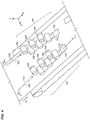
- FIG. 4 is a perspective view of angled deposition stations 140 in an illustrative embodiment. Specifically, FIG. 4 corresponds with view arrows 4 of FIG. 3 .
- FIG. 4 illustrates relationships in motion and angle found between angled deposition stations 140 and web 120.
- each roller 346 of one of angled deposition stations 140 may dispense tows 142 at a velocity V2.
- the direction 412 of V2 may deviate from the direction 430 of V1 by an angle ⁇ 1.
- tows 142 may have a lengthwise axis (LI) that is not parallel with the lengthwise axis of web 120 (e.g., the process direction).
- LI lengthwise axis
- the rollers 346 may further be moved at a velocity V3.
- the magnitude and/or direction of V2 and/or V3 may be adjusted while rollers 346 are dispensing tows, for example in order to ensure that the tows maintain a constant angle with respect to web 120 and do not exhibit wrinkles.
- another of angled deposition stations 140 may dispense tows 142 at a velocity V4, in a direction 422 that deviates from direction 420 of V1 by an angle ⁇ 2.
- the rollers 346 of the other angled deposition station may be moved at a velocity V5, and the magnitude and/or direction of V4 and/or V5 may be adjusted while rollers 346 are dispensing tows.
- FIG. 5 is a perspective view of a perpendicular deposition station 150 in an illustrative embodiment.
- FIG. 5 corresponds with view arrows 5 of FIG. 3 .
- roller 356 (or the entirety of the perpendicular deposition station 150) is moved at velocity V1 in the web direction, such that the roller 356 does not move with respect to web 120 in the process direction when dispensing tow 152.
- roller 356 is moved at velocity V6 along the Z direction 500, which enables perpendicular deposition station 150 to apply tows having a lengthwise axis (L2) that are perpendicular to the lengthwise axis (e.g., the process direction) of web 120.
- Any of the deposition stations described herein may be moved back to a default position and/or orientation after completing layup for a preform or a portion of a preform. This enables the deposition stations to initiate layup of a next preform.
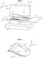
- FIG. 6 is a perspective view of a stamp 162 shaping a portion of a web 120 in an illustrative embodiment, and corresponds with view arrows 6 of FIG. 3 .
- Stamp 162 specifically shapes web 120, along with any tows that have been adhered to web 120.
- Stamp 162 may apply a predetermined amount of pressure to shape web 120 (e.g., hundreds of kilopascals of pressure).
- FIG. 6 further illustrates contour 610 at stamp 162, as well as contour 620 at mandrel 164. After stamp 162 has completed its operations, the portion of web 120 (and any adhered tows) will follow contour 610 and contour 620.
- FIG. 7 illustrates a completed preform 700 fabricated via preform fabrication system 100. The preform 700 has been shaped and cut, and includes tows 142 and a tow 152 at desired locations.
- FIG. 8 is a block diagram of a preform fabrication system 800 in an illustrative embodiment.
- Preform fabrication system 800 includes dispensing spool 810, which provides web 820, and take-up spool 830, which receives portions of web 820 after they have been cut at forming station 840.
- stamp 842 is driven into mandrel 844, and cutting tool 846 is driven downward to cut a preform from web 820.
- Deposition system 850 includes a spool 852 that provides a tow 858 of fiber reinforced material to a roller 854, which dispenses the tow 858 onto web 120.
- An actuator 856 may dynamically adjust a position and/or angle of roller 854 during this process.
- deposition system 860 includes a spool 862, a tow 868, a roller 864, and an actuator 866
- deposition system 870 includes a spool 872, a tow 878, a roller 874-, and an actuator 876.
- an unheated roller may be used, and heat may be applied by separate heaters (such as infrared heaters, not shown) prior to compaction
- a heated roller may be used.
- Support 890 is a conveyor having a belt 892 and multiple rollers 894. Belt 892 supports web 820, and is conveyed in the process direction of web 820 in order to prevent rubbing or abrasion against web 820.
- Controller 880 manages the operations of the various components discussed above.
- controller 880 may implement instructions stored in a Numerical Control (NC) program in order to direct the timing, movements, and other operations of various coupled components.
- Controller 880 may for example receive feedback from one or more sensors 882 (e.g., infrared sensors, motion sensors, rotational sensors, etc.), and may use this input to control the timing and movements discussed above. Such feedback may indicate a location or angle of a tow relative to the web.
- Controller 880 may be implemented, for example, as custom circuitry, as a hardware processor executing programmed instructions, or some combination thereof.
- method 900 may include specification and design 904 of the aircraft 902 and material procurement 906.
- component and subassembly manufacturing 908 and system integration 910 of the aircraft 902 takes place.
- the aircraft 902 may go through certification and delivery 912 in order to be placed in service 914.
- the aircraft 902 is scheduled for routine work in maintenance and service 916 (which may also include modification, reconfiguration, refurbishment, and so on).
- Apparatus and methods embodied herein may be employed during any one or more suitable stages of the production and service described in method 900 (e.g., specification and design 904, material procurement 906, component and subassembly manufacturing 908, system integration 910, certification and delivery 912, service 914, maintenance and service 916) and/or any suitable component of aircraft 902 (e.g., airframe 918, systems 920, interior 922, propulsion system 924, electrical system 926, hydraulic system 928, environmental 930).
- any suitable component of aircraft 902 e.g., airframe 918, systems 920, interior 922, propulsion system 924, electrical system 926, hydraulic system 928, environmental 930.
- Each of the processes of method 900 may be performed or carried out by a system integrator, a third party, and/or an operator (e.g., a customer).
- a system integrator may include without limitation any number of aircraft manufacturers and major-system subcontractors
- a third party may include without limitation any number of vendors, subcontractors, and suppliers
- an operator may be an airline, leasing company, military entity, service organization, and so on.
- the aircraft 902 produced by method 900 may include an airframe 918 with a plurality of systems 920 and an interior 922.
- systems 920 include one or more of a propulsion system 924, an electrical system 926, a hydraulic system 928, and an environmental system 930. Any number of other systems may be included.
- an aerospace example is shown, the principles of the invention may be applied to other industries, such as the automotive industry.
- apparatus and methods embodied herein may be employed during any one or more of the stages of the production and service described in method 900.
- components or subassemblies corresponding to component and subassembly manufacturing 908 may be fabricated or manufactured in a manner similar to components or subassemblies produced while the aircraft 902 is in service.
- one or more apparatus embodiments, method embodiments, or a combination thereof may be utilized during the subassembly manufacturing 908 and system integration 910, for example, by substantially expediting assembly of or reducing the cost of an aircraft 902.
- one or more of apparatus embodiments, method embodiments, or a combination thereof may be utilized while the aircraft 902 is in service, for example and without limitation during the maintenance and service 916.
- the techniques and systems described herein may be used for material procurement 906, component and subassembly manufacturing 908, system integration 910, service 914, and/or maintenance and service 916, and/or maybe used for airframe 918 and/or interior 922.
- These techniques and systems may even be utilized for systems 920, including, for example, propulsion system 924, electrical system 926, hydraulic 928, and/or environmental system 930.
- a part comprises a portion of airframe 918, and is manufactured during component and subassembly manufacturing 908.
- the part may then be assembled into an aircraft in system integration 910, and then be utilized in service 914 until wear renders the part unusable. Then, in maintenance and service 916, the part may be discarded and replaced with a newly manufactured part.
- Inventive components and methods may be utilized throughout component and subassembly manufacturing 908 in order to manufacture new parts.
- control elements e.g., electrical or electronic components
- a processor implementing software
- a processor implementing firmware or some combination of these.
- an element may be implemented as dedicated hardware.
- Dedicated hardware elements may be referred to as "processors", “controllers”, or some similar terminology.
- the functions may be provided by a single dedicated processor, by a single shared processor, or by a plurality of individual processors, some of which may be shared.
- processor or “controller” should not be construed to refer exclusively to hardware capable of executing software, and may implicitly include, without limitation, digital signal processor (DSP) hardware, a network processor, application specific integrated circuit (ASIC) or other circuitry, field programmable gate array (FPGA), read only memory (ROM) for storing software, random access memory (RAM), non-volatile storage, logic, or some other physical hardware component or module.
- DSP digital signal processor
- ASIC application specific integrated circuit
- FPGA field programmable gate array
- ROM read only memory
- RAM random access memory
- non-volatile storage logic, or some other physical hardware component or module.
- a control element may be implemented as instructions executable by a processor or a computer to perform the functions of the element.
- instructions are software, program code, and firmware.
- the instructions are operational when executed by the processor to direct the processor to perform the functions of the element.
- the instructions may be stored on storage devices that are readable by the processor. Some examples of the storage devices are digital or solid-state memories, magnetic storage media such as a magnetic disks and magnetic tapes, hard drives, or optically readable digital data storage media.
Landscapes
- Engineering & Computer Science (AREA)
- Mechanical Engineering (AREA)
- Chemical & Material Sciences (AREA)
- Composite Materials (AREA)
- Robotics (AREA)
- Life Sciences & Earth Sciences (AREA)
- Forests & Forestry (AREA)
- Textile Engineering (AREA)
- Moulding By Coating Moulds (AREA)
- Reinforced Plastic Materials (AREA)
Applications Claiming Priority (1)
| Application Number | Priority Date | Filing Date | Title |
|---|---|---|---|
| US16/045,982 US11052571B2 (en) | 2018-07-26 | 2018-07-26 | Continuous fabrication for composite preforms |
Publications (2)
| Publication Number | Publication Date |
|---|---|
| EP3599083A1 true EP3599083A1 (de) | 2020-01-29 |
| EP3599083B1 EP3599083B1 (de) | 2026-04-08 |
Family
ID=66429281
Family Applications (1)
| Application Number | Title | Priority Date | Filing Date |
|---|---|---|---|
| EP19172794.0A Active EP3599083B1 (de) | 2018-07-26 | 2019-05-06 | Kontinuierliche herstellung für verbundwerkstoffvorformen |
Country Status (7)
| Country | Link |
|---|---|
| US (1) | US11052571B2 (de) |
| EP (1) | EP3599083B1 (de) |
| JP (1) | JP7510248B2 (de) |
| KR (1) | KR102892598B1 (de) |
| CN (1) | CN110774619A (de) |
| CA (1) | CA3044125C (de) |
| RU (1) | RU2019113560A (de) |
Families Citing this family (5)
| Publication number | Priority date | Publication date | Assignee | Title |
|---|---|---|---|---|
| EP3967480B1 (de) * | 2020-09-15 | 2025-12-10 | The Boeing Company | Systeme und verfahren zur formung von verbundelementen |
| US12195201B2 (en) * | 2020-11-18 | 2025-01-14 | The Boeing Company | Composite preform assembly method and apparatus |
| US11780181B2 (en) * | 2020-11-18 | 2023-10-10 | The Boeing Company | Multi-lane tows for use with ply-by-ply forming machines |
| US11618177B1 (en) | 2022-04-12 | 2023-04-04 | Bradley W Boesel | Orbital knife |
| CN115284378A (zh) * | 2022-09-28 | 2022-11-04 | 南通君泽医疗科技有限公司 | 一种无纺布加工打孔设备 |
Citations (3)
| Publication number | Priority date | Publication date | Assignee | Title |
|---|---|---|---|---|
| US4938824A (en) * | 1987-01-23 | 1990-07-03 | Thiokol Corporation | Method for making a composite component using a transverse tape |
| US6607626B2 (en) * | 2000-07-28 | 2003-08-19 | Hypercar Inc. | Process and equipment for manufacture of advanced composite structures |
| DE102012111761A1 (de) * | 2012-12-04 | 2014-06-05 | Rehau Ag + Co. | Verfahren zum Herstellen eines zweilagigen oder mehrlagigen bahnförmigen Halbzeugmaterials mit wenigstens einer unidirektional faserverstärkten Lage und System zum Durchführen des Verfahrens |
Family Cites Families (22)
| Publication number | Priority date | Publication date | Assignee | Title |
|---|---|---|---|---|
| US3556888A (en) | 1967-06-23 | 1971-01-19 | Glastrusions | Pultrusion machine and method |
| JPS5160775A (en) * | 1974-11-08 | 1976-05-26 | Shigeru Kogyo Kk | Sharyoyonaisozaino seizohoho |
| TW363012B (en) * | 1995-05-01 | 1999-07-01 | Mitsui Chemicals Inc | Manufacturing method for laminated plates |
| JP3894035B2 (ja) * | 2001-07-04 | 2007-03-14 | 東レ株式会社 | 炭素繊維強化基材、それからなるプリフォームおよび複合材料 |
| US6635004B2 (en) * | 2001-09-14 | 2003-10-21 | Paragon Trade Brands, Inc. | Apparatus and method for removing material from a fabric web |
| JP2003251702A (ja) * | 2002-03-01 | 2003-09-09 | Toray Ind Inc | 強化繊維基材の裁断方法およびプリフォームの製造方法ならびにその製造装置 |
| US7527222B2 (en) * | 2004-04-06 | 2009-05-05 | The Boeing Company | Composite barrel sections for aircraft fuselages and other structures, and methods and systems for manufacturing such barrel sections |
| KR100908423B1 (ko) * | 2004-09-18 | 2009-07-21 | 파우레시아 이넨라움 시스템 게엠바하 | 프레스 몰딩 장치 및 프레스 몰딩으로 부품을 제조하는방법 |
| US8361262B2 (en) | 2007-11-08 | 2013-01-29 | The Boeing Company | Method and apparatus for low-bulk toughened fabrics for low-pressure molding processes |
| US8094027B2 (en) * | 2007-12-19 | 2012-01-10 | Abbott Laboratories | Method for molding an object containing a radio frequency identification tag |
| FR2928293B1 (fr) * | 2008-03-07 | 2016-09-23 | Duqueine Rhone Alpes | Procede de fabrication d'un produit composite multi axial plan et produit obtenu par ce procede |
| US9090028B2 (en) * | 2008-04-17 | 2015-07-28 | The Boeing Company | Method for producing contoured composite structures and structures produced thereby |
| ES2670225T3 (es) * | 2009-10-20 | 2018-05-29 | Vestas Wind Systems A/S | Método para fabricar un cuerpo de materiales compuestos y una disposición de fabricación de cuerpo de materiales compuestos |
| DE102010002844A1 (de) * | 2010-03-13 | 2011-09-15 | Dieffenbacher Gmbh + Co. Kg | Verfahren, Anlage und Harzmatte zur Herstellung von faserverstärkten Formteilen in einer Formpresse |
| EP2987819B1 (de) * | 2013-04-19 | 2019-02-27 | Toray Industries, Inc. | Verfahren zur herstellung eines verstärkenden faserbogens |
| US20160101543A1 (en) * | 2013-12-03 | 2016-04-14 | The Boeing Company | Hybrid Laminate and Molded Composite Structures |
| DE102014205479B4 (de) | 2014-03-25 | 2025-03-27 | Bayerische Motoren Werke Aktiengesellschaft | Verfahren zur Herstellung eines Faservorformlings für ein Faserverbundbauteil |
| US10406798B2 (en) * | 2014-03-31 | 2019-09-10 | Goodrich Corporation | Method to transport and lay down dry fiber bundles |
| US20150344347A1 (en) * | 2014-05-29 | 2015-12-03 | Corning Incorporated | Apparatuses for steering flexible glass webs and methods for using the same |
| CN107548339B (zh) * | 2015-02-23 | 2020-08-07 | 大众汽车股份有限公司 | 纤维增强构件或半成品的制备方法 |
| JP6681803B2 (ja) * | 2016-08-04 | 2020-04-15 | 津田駒工業株式会社 | 強化繊維材料の供給装置、及びその供給装置における強化繊維材料の切断方法 |
| US10668683B2 (en) * | 2016-09-15 | 2020-06-02 | The Boeing Company | Gap fillers for composite materials |
-
2018
- 2018-07-26 US US16/045,982 patent/US11052571B2/en active Active
-
2019
- 2019-05-06 RU RU2019113560A patent/RU2019113560A/ru unknown
- 2019-05-06 EP EP19172794.0A patent/EP3599083B1/de active Active
- 2019-05-23 CA CA3044125A patent/CA3044125C/en active Active
- 2019-05-24 KR KR1020190060976A patent/KR102892598B1/ko active Active
- 2019-07-12 JP JP2019129718A patent/JP7510248B2/ja active Active
- 2019-07-16 CN CN201910641865.9A patent/CN110774619A/zh active Pending
Patent Citations (3)
| Publication number | Priority date | Publication date | Assignee | Title |
|---|---|---|---|---|
| US4938824A (en) * | 1987-01-23 | 1990-07-03 | Thiokol Corporation | Method for making a composite component using a transverse tape |
| US6607626B2 (en) * | 2000-07-28 | 2003-08-19 | Hypercar Inc. | Process and equipment for manufacture of advanced composite structures |
| DE102012111761A1 (de) * | 2012-12-04 | 2014-06-05 | Rehau Ag + Co. | Verfahren zum Herstellen eines zweilagigen oder mehrlagigen bahnförmigen Halbzeugmaterials mit wenigstens einer unidirektional faserverstärkten Lage und System zum Durchführen des Verfahrens |
Also Published As
| Publication number | Publication date |
|---|---|
| US11052571B2 (en) | 2021-07-06 |
| KR102892598B1 (ko) | 2025-11-27 |
| JP7510248B2 (ja) | 2024-07-03 |
| CA3044125C (en) | 2023-10-03 |
| KR20200012718A (ko) | 2020-02-05 |
| EP3599083B1 (de) | 2026-04-08 |
| CA3044125A1 (en) | 2020-01-26 |
| JP2020037254A (ja) | 2020-03-12 |
| US20200031019A1 (en) | 2020-01-30 |
| CN110774619A (zh) | 2020-02-11 |
| RU2019113560A (ru) | 2020-11-06 |
Similar Documents
| Publication | Publication Date | Title |
|---|---|---|
| CA3044125C (en) | Continuous fabrication for composite preforms | |
| US8591685B2 (en) | Method and apparatus for producing composite fillers | |
| EP2540480B1 (de) | Automatische Harz- und Faserablagerung zur Harzinfusion | |
| KR20200116406A (ko) | 자동화된 섬유배치 시스템과 방법 및 이로부터 생산된 제품 | |
| US20050274446A1 (en) | Metal fiber lamination method and system | |
| JP7558691B2 (ja) | ハイブリッド複合材部品用の編み組み繊維のトウのレイアップ及び製造 | |
| EP4000887B1 (de) | Verfahren und vorrichtung zum platzieren von mehrspurigen faserstrangen | |
| EP4011588B1 (de) | Platzierung von vorformlingen für strebenabschnitte auf einem vorformling für ein tragflächenelement | |
| US11597167B2 (en) | Continuous-line fabrication for composite parts | |
| NL2027407B1 (en) | Multi-lane tows for use with ply-by-ply forming machines | |
| US11780181B2 (en) | Multi-lane tows for use with ply-by-ply forming machines | |
| NL2027406B1 (en) | Multi-lane tows for use with ply-by-ply forming machines | |
| EP4000889B1 (de) | Endlosbandfertigung für verbundteile | |
| NL2027424B1 (en) | Continuous-line fabrication for composite parts | |
| WO2024124100A1 (en) | Methods for preparing and using prepreg layer segments for additive manufacturing and products produced therefrom | |
| JP2022095538A (ja) | 複合材プリフォーム組立方法及び装置 |
Legal Events
| Date | Code | Title | Description |
|---|---|---|---|
| PUAI | Public reference made under article 153(3) epc to a published international application that has entered the european phase |
Free format text: ORIGINAL CODE: 0009012 |
|
| STAA | Information on the status of an ep patent application or granted ep patent |
Free format text: STATUS: REQUEST FOR EXAMINATION WAS MADE |
|
| 17P | Request for examination filed |
Effective date: 20190506 |
|
| AK | Designated contracting states |
Kind code of ref document: A1 Designated state(s): AL AT BE BG CH CY CZ DE DK EE ES FI FR GB GR HR HU IE IS IT LI LT LU LV MC MK MT NL NO PL PT RO RS SE SI SK SM TR |
|
| AX | Request for extension of the european patent |
Extension state: BA ME |
|
| STAA | Information on the status of an ep patent application or granted ep patent |
Free format text: STATUS: EXAMINATION IS IN PROGRESS |
|
| 17Q | First examination report despatched |
Effective date: 20220121 |
|
| RAP3 | Party data changed (applicant data changed or rights of an application transferred) |
Owner name: THE BOEING COMPANY |
|
| RIC1 | Information provided on ipc code assigned before grant |
Ipc: B29C 70/20 20060101AFI20250722BHEP Ipc: B29B 11/16 20060101ALI20250722BHEP Ipc: B29C 70/38 20060101ALI20250722BHEP Ipc: B29C 70/46 20060101ALI20250722BHEP Ipc: B29C 70/50 20060101ALI20250722BHEP Ipc: B29C 70/54 20060101ALI20250722BHEP Ipc: B29L 31/30 20060101ALN20250722BHEP |
|
| GRAP | Despatch of communication of intention to grant a patent |
Free format text: ORIGINAL CODE: EPIDOSNIGR1 |
|
| STAA | Information on the status of an ep patent application or granted ep patent |
Free format text: STATUS: GRANT OF PATENT IS INTENDED |
|
| RIC1 | Information provided on ipc code assigned before grant |
Ipc: B29C 70/20 20060101AFI20250814BHEP Ipc: B29B 11/16 20060101ALI20250814BHEP Ipc: B29C 70/38 20060101ALI20250814BHEP Ipc: B29C 70/46 20060101ALI20250814BHEP Ipc: B29C 70/50 20060101ALI20250814BHEP Ipc: B29C 70/54 20060101ALI20250814BHEP Ipc: B29L 31/30 20060101ALN20250814BHEP |
|
| GRAJ | Information related to disapproval of communication of intention to grant by the applicant or resumption of examination proceedings by the epo deleted |
Free format text: ORIGINAL CODE: EPIDOSDIGR1 |
|
| STAA | Information on the status of an ep patent application or granted ep patent |
Free format text: STATUS: EXAMINATION IS IN PROGRESS |
|
| INTG | Intention to grant announced |
Effective date: 20250912 |
|
| GRAP | Despatch of communication of intention to grant a patent |
Free format text: ORIGINAL CODE: EPIDOSNIGR1 |
|
| STAA | Information on the status of an ep patent application or granted ep patent |
Free format text: STATUS: GRANT OF PATENT IS INTENDED |
|
| INTC | Intention to grant announced (deleted) | ||
| RIC1 | Information provided on ipc code assigned before grant |
Ipc: B29C 70/20 20060101AFI20251013BHEP Ipc: B29B 11/16 20060101ALI20251013BHEP Ipc: B29C 70/38 20060101ALI20251013BHEP Ipc: B29C 70/46 20060101ALI20251013BHEP Ipc: B29C 70/50 20060101ALI20251013BHEP Ipc: B29C 70/54 20060101ALI20251013BHEP Ipc: B29L 31/30 20060101ALN20251013BHEP |
|
| INTG | Intention to grant announced |
Effective date: 20251029 |
|
| P01 | Opt-out of the competence of the unified patent court (upc) registered |
Free format text: CASE NUMBER: UPC_APP_0011001_3599083/2025 Effective date: 20251024 |
|
| GRAS | Grant fee paid |
Free format text: ORIGINAL CODE: EPIDOSNIGR3 |
|
| GRAA | (expected) grant |
Free format text: ORIGINAL CODE: 0009210 |
|
| STAA | Information on the status of an ep patent application or granted ep patent |
Free format text: STATUS: THE PATENT HAS BEEN GRANTED |
|
| AK | Designated contracting states |
Kind code of ref document: B1 Designated state(s): AL AT BE BG CH CY CZ DE DK EE ES FI FR GB GR HR HU IE IS IT LI LT LU LV MC MK MT NL NO PL PT RO RS SE SI SK SM TR |
|
| REG | Reference to a national code |
Ref country code: CH Ref legal event code: F10 Free format text: ST27 STATUS EVENT CODE: U-0-0-F10-F00 (AS PROVIDED BY THE NATIONAL OFFICE) Effective date: 20260408 Ref country code: GB Ref legal event code: FG4D |
|
| REG | Reference to a national code |
Ref country code: DE Ref legal event code: R096 Ref document number: 602019083308 Country of ref document: DE |