EP3599092B1 - Verfahren zum aufbringen einer funktions-schicht auf einen behälter - Google Patents
Verfahren zum aufbringen einer funktions-schicht auf einen behälter Download PDFInfo
- Publication number
- EP3599092B1 EP3599092B1 EP19182132.1A EP19182132A EP3599092B1 EP 3599092 B1 EP3599092 B1 EP 3599092B1 EP 19182132 A EP19182132 A EP 19182132A EP 3599092 B1 EP3599092 B1 EP 3599092B1
- Authority
- EP
- European Patent Office
- Prior art keywords
- container
- flame
- flame pyrolysis
- plasma
- devices
- Prior art date
- Legal status (The legal status is an assumption and is not a legal conclusion. Google has not performed a legal analysis and makes no representation as to the accuracy of the status listed.)
- Active
Links
Images

Classifications
-
- B—PERFORMING OPERATIONS; TRANSPORTING
- B41—PRINTING; LINING MACHINES; TYPEWRITERS; STAMPS
- B41J—TYPEWRITERS; SELECTIVE PRINTING MECHANISMS, i.e. MECHANISMS PRINTING OTHERWISE THAN FROM A FORME; CORRECTION OF TYPOGRAPHICAL ERRORS
- B41J3/00—Typewriters or selective printing or marking mechanisms characterised by the purpose for which they are constructed
- B41J3/407—Typewriters or selective printing or marking mechanisms characterised by the purpose for which they are constructed for marking on special material
- B41J3/4073—Printing on three-dimensional objects not being in sheet or web form, e.g. spherical or cubic objects
- B41J3/40733—Printing on cylindrical or rotationally symmetrical objects, e. g. on bottles
-
- B—PERFORMING OPERATIONS; TRANSPORTING
- B05—SPRAYING OR ATOMISING IN GENERAL; APPLYING FLUENT MATERIALS TO SURFACES, IN GENERAL
- B05B—SPRAYING APPARATUS; ATOMISING APPARATUS; NOZZLES
- B05B13/00—Machines or plants for applying liquids or other fluent materials to surfaces of objects or other work by spraying, not covered by groups B05B1/00 - B05B11/00
- B05B13/02—Means for supporting work; Arrangement or mounting of spray heads; Adaptation or arrangement of means for feeding work
- B05B13/0221—Means for supporting work; Arrangement or mounting of spray heads; Adaptation or arrangement of means for feeding work characterised by the means for moving or conveying the objects or other work, e.g. conveyor belts
- B05B13/0235—Means for supporting work; Arrangement or mounting of spray heads; Adaptation or arrangement of means for feeding work characterised by the means for moving or conveying the objects or other work, e.g. conveyor belts the movement of the objects being a combination of rotation and linear displacement
-
- B—PERFORMING OPERATIONS; TRANSPORTING
- B05—SPRAYING OR ATOMISING IN GENERAL; APPLYING FLUENT MATERIALS TO SURFACES, IN GENERAL
- B05B—SPRAYING APPARATUS; ATOMISING APPARATUS; NOZZLES
- B05B13/00—Machines or plants for applying liquids or other fluent materials to surfaces of objects or other work by spraying, not covered by groups B05B1/00 - B05B11/00
- B05B13/02—Means for supporting work; Arrangement or mounting of spray heads; Adaptation or arrangement of means for feeding work
- B05B13/0221—Means for supporting work; Arrangement or mounting of spray heads; Adaptation or arrangement of means for feeding work characterised by the means for moving or conveying the objects or other work, e.g. conveyor belts
- B05B13/0242—Means for supporting work; Arrangement or mounting of spray heads; Adaptation or arrangement of means for feeding work characterised by the means for moving or conveying the objects or other work, e.g. conveyor belts the objects being individually presented to the spray heads by a rotating element, e.g. turntable
-
- B—PERFORMING OPERATIONS; TRANSPORTING
- B05—SPRAYING OR ATOMISING IN GENERAL; APPLYING FLUENT MATERIALS TO SURFACES, IN GENERAL
- B05B—SPRAYING APPARATUS; ATOMISING APPARATUS; NOZZLES
- B05B7/00—Spraying apparatus for discharge of liquids or other fluent materials from two or more sources, e.g. of liquid and air, of powder and gas
- B05B7/16—Spraying apparatus for discharge of liquids or other fluent materials from two or more sources, e.g. of liquid and air, of powder and gas incorporating means for heating or cooling the material to be sprayed
- B05B7/20—Spraying apparatus for discharge of liquids or other fluent materials from two or more sources, e.g. of liquid and air, of powder and gas incorporating means for heating or cooling the material to be sprayed by flame or combustion
-
- B—PERFORMING OPERATIONS; TRANSPORTING
- B41—PRINTING; LINING MACHINES; TYPEWRITERS; STAMPS
- B41J—TYPEWRITERS; SELECTIVE PRINTING MECHANISMS, i.e. MECHANISMS PRINTING OTHERWISE THAN FROM A FORME; CORRECTION OF TYPOGRAPHICAL ERRORS
- B41J11/00—Devices or arrangements of selective printing mechanisms, e.g. ink-jet printers or thermal printers, for supporting or handling copy material in sheet or web form
- B41J11/0015—Devices or arrangements of selective printing mechanisms, e.g. ink-jet printers or thermal printers, for supporting or handling copy material in sheet or web form for treating before, during or after printing or for uniform coating or laminating the copy material before or after printing
-
- B—PERFORMING OPERATIONS; TRANSPORTING
- B41—PRINTING; LINING MACHINES; TYPEWRITERS; STAMPS
- B41J—TYPEWRITERS; SELECTIVE PRINTING MECHANISMS, i.e. MECHANISMS PRINTING OTHERWISE THAN FROM A FORME; CORRECTION OF TYPOGRAPHICAL ERRORS
- B41J3/00—Typewriters or selective printing or marking mechanisms characterised by the purpose for which they are constructed
- B41J3/407—Typewriters or selective printing or marking mechanisms characterised by the purpose for which they are constructed for marking on special material
- B41J3/4073—Printing on three-dimensional objects not being in sheet or web form, e.g. spherical or cubic objects
Definitions
- the present invention relates to a method for treating a surface of a container according to claim 1 and a container treatment machine for treating a surface of a container according to claim 9.
- plastic-based containers especially PET and other materials such as glass or metal
- PET and other materials such as glass or metal
- the materials to be applied also adhere to the surface of the container. Since the properties (physical and/or chemical) of the surface of containers depend on the material used and are not homogeneous even for a given container, various options have been specified in the past to improve the properties of the surface of the container with regard to wetting with printing inks or other materials.
- the primer must also adhere to the surface of the container and its composition therefore depends on the container material, which can also influence the adhesive properties of the printing ink applied to the primer.
- the EP 1 148 036 B1 proposes to first oxidize the surface of a container using burners and then to apply an adhesion-promoting functional layer to the oxidized surface using flame pyrolysis, whereby silicon-containing materials are used in particular. Due to the many different process steps required to pretreat the surface of the container, the pretreatment of the container becomes complex and is also highly dependent on the underlying container material. In addition, these processes carry the risk of the container surface becoming charred.
- the JP 2018 024559 A discloses a method for producing a surface-treated resin-coated glass bottle, comprising a step of forming a resin layer on at least a part of an outer bottle surface to obtain a resin-coated bottle; and a step of subjecting a surface of the resin layer of the coated glass bottle to a treatment by a flame obtained by burning a gas mixture of hydrocarbon, oxygen and a silicon-containing compound to form a silicate layer on the surface of the resin layer.
- the invention of the EP 2 799 241 A2 relates to a method and a device for directly printing plastic containers, wherein in a first step an intermediate layer is applied to the container to be printed with the aid of a first device and in a second step the container is printed in certain areas with the aid of a second device, characterized in that the intermediate layer forms a bond with the container and the printing layer which is insoluble in aqueous solutions with a pH value between 3 and 10 and readily soluble in aqueous solutions with a pH value in a range less than 3 and/or greater than 10; and a recycling process for a plastic container provided with an intermediate layer.
- a printer equipped with a surface treatment system which includes a holding device for securely holding an object in the holding device and a plurality of surface treatment devices, each surface treatment device treating the object in a different manner than the other surface treatment devices, so that the printer can treat a wide range of materials for direct printing on the object.
- the EN 10 2013 110125 A1 discloses a method and a device for surface pretreatment of a three-dimensional body for preparing a three-dimensional surface of the body for printing, in which the surface to be printed is cleaned and/or adapted to the surface tension of the printing material relative to a surface treatment device in order to treat the entire surface to be printed. It is provided that the three-dimensional body is subjected to surface treatment in a transport section of a transport device.
- the EN 10 2013 215637 A1 describes a device for printing containers, comprising at least one transport path in which containers can be transported and a plurality of printing modules for printing the containers, characterized in that at least two printing modules are digital printing modules and differ in terms of their digital printing technology and a corresponding method.
- the technical problem to be solved is therefore to specify a method and a container treatment machine which achieve an improvement in the wettability of the surface of a container, but at the same time place less specific demands on the complexity of the method carried out or the container treatment machine.
- the method according to the invention for treating a surface of a container, such as a bottle, in the packaging industry comprises applying a functional layer to a non-oxidized surface of the container in a container treatment machine.
- the functional layer is a layer that is applied to the surface of the container before the container is wetted with a printed image or printing ink.
- the application of the functional layer does not include any processes that require digital printing of such a functional layer.
- the non-oxidized surface of the container is understood to be that surface which has not been treated in a previous process step by an oxidizing flame or other processes which would oxidize the molecular groups on the surface of the container.
- the functional layer is applied to such a non-oxidized surface, preceding process steps that already oxidize or otherwise process the surface of the container can be omitted, so that the entire process is less complex, but at the same time the formation of the functional layer on the surface of the container ensures good wettability by printing inks.
- this makes it possible to apply a uniform functional layer to a wide variety of substrates, creating a uniform, printable surface for all types of container (substrates).
- the development effort for printing inks that can be used on a wide variety of substrates can thus be eliminated entirely or at least significantly reduced.
- the functional layer is applied by means of flame pyrolysis, whereby a preferably gaseous precursor is added to the flame, which forms the functional layer on and/or with the surface of the container.
- the container treatment machine comprises two flame pyrolysis devices, wherein the non-oxidized surface of the container is exposed to flame in the presence of a precursor and the functional layer is applied to at least the area on the non-oxidized surface that is exposed to flame by the flame pyrolysis devices.
- the exposed area of the surface is the area that is in direct contact with the flame generated by the flame pyrolysis devices.
- the precursor can be introduced into the flame or the flame pyrolysis device itself as a gas or droplet, so that it also hits the surface of the container in the area of the flame and forms an adhesive functional layer there through chemical reactions on the surface. It goes without saying that the precursor originally introduced into the flame no longer has to be chemically identical to the material that forms the "functional layer". In any case, however, the functional layer is at least partially formed by the precursor.
- the embodiment according to the invention comprises two flame pyrolysis devices and the containers are transported in a transport device which transports the containers past the flame pyrolysis devices in the transport direction, wherein the flame pyrolysis devices are arranged one after the other in the transport direction and flame the non-oxidized surface of the container one after the other, wherein the flame pyrolysis devices are aligned such that a first flame pyrolysis device applies the flame in a first direction and a second flame pyrolysis device applies the flame in a second direction. Since oxidation processes preceding the flame application with the precursor are eliminated, This embodiment allows the surface of the container to be exposed to the flame with the precursor as quickly as possible, while at the same time the layer thickness of the functional layer can be advantageously adjusted and increased.
- the container treatment machine comprises a plasma nozzle, wherein the surface of the container is exposed to a plasma containing the precursor and the functional layer is applied at least in the area on the non-oxidized surface which is exposed to the plasma by the plasma nozzle.
- the plasma is preferably a low-temperature plasma.
- the functional layer can be applied to the surface of the container in a virtually non-destructive manner, which can prevent accidental damage and carbonization of the surface of the container.
- the container is moved along its longitudinal axis while the plasma nozzle applies the plasma to the surface of the container. Since the effective area of the plasma nozzle is usually small compared to the dimensions of the surface of the container, the entire surface of the container can be applied with this embodiment.
- the container is rotated about an axis (in particular its longitudinal axis) while the functional layer is applied to the non-oxidized surface. In this way, an all-round coating with the functional layer can also be achieved.
- the movement of the container relative to the plasma nozzle is controlled such that the distance of the surface exposed to the plasma from the plasma nozzle is always constant or essentially constant.
- This can include the container being moved along an axis (in particular its longitudinal axis) and/or rotating (at the same time).
- the container can be moved translationally in a plane perpendicular to the axis, so that, for example, the distance of the axis from the plasma nozzle is changed. This is particularly advantageous for non-round containers (containers with a non-round cross-section) and contoured containers, also to avoid collisions with the plasma nozzle.
- the distance between the surface and the plasma nozzle is only "essentially" constant means that, in particular in the case of embossings or raised texts on the surface of the container or elevations/depressions on the surface that have only a small spatial extent, an adjustment of the distance between the surface and the container does not take place if the extent of these elevations/depressions, ebmossings, raised texts in the direction of the plasma nozzle is significantly smaller than the distance of the remaining surface to the plasma nozzle (for example, less than 20% or less than 10% or less than 2% of the distance between the remaining surface and the plasma nozzle).
- the distance of the non-oxidized surface, which is exposed to flames by the flame pyrolysis device or to which plasma is applied by the plasma nozzle, from the flame pyrolysis device or the plasma nozzle remains constant, while the container is rotated relative to the flame pyrolysis device or the plasma nozzle. In the case of non-round containers, this ensures that the functional layer is applied over the entire surface under conditions that are as uniform as possible.
- the precursor can further comprise at least one of silicon, organometallic compounds, titanium, silicon-containing compounds. These can be reliably applied to the surface of containers and can positively influence its properties with regard to wetting with printing inks.
- the container treatment machine for treating a surface of a container, such as a bottle, in the packaging industry, comprises a transport device for transporting the containers along a transport direction and two flame pyrolysis devices which are arranged and designed to flame a surface of a container which is transported in the transport device and to apply a functional layer and is characterized in that the flame pyrolysis devices are both arranged on the same side of the transport device and wherein the flame pyrolysis devices are arranged one after the other in the transport direction and are aligned such that a first flame pyrolysis device applies the flame in a first direction and a second flame pyrolysis device applies the flame in a second direction.
- This special arrangement of the flame pyrolysis devices facilitates access to them and also simplifies the design of the lines necessary for introducing the precursor into the flames, since these do not have to be routed around the entire container treatment machine, but only have to be provided on one side.
- first direction and the second direction must at least be designed in such a way that the flame is directed towards the transport device in such a way that a container located therein, which is transported past the flame pyrolysis devices, can also be exposed to the flames.
- the arrangement of the flame pyrolysis devices In this way, it can be ensured that the entire surface of the container is exposed to the flame, preferably homogeneously.
- first direction and the second direction are parallel to one another. This embodiment allows different areas of a container moving past the flame pyrolysis devices to be exposed to flames at the same time, which can reduce the overall time required to apply a functional layer with a predetermined thickness.
- first and second flame pyrolysis devices have different distances from the transport device. This can be particularly advantageous when flame-treating containers with a non-round cross-section.
- ⁇ ⁇ + ⁇
- ⁇ and ⁇ are the angles enclosed by the first and second directions with a plane perpendicular to the transport direction.
- the flame pyrolysis devices are arranged in such a way that an area of the surface of the container to be coated with the functional layer is simultaneously exposed to flames from different directions by both flame pyrolysis devices. This increases the application rate of the precursor for forming the functional layer on the surface and can simultaneously ensure that areas of the surface lying in the shadow area of the first flame are also exposed to the second flame.
- the transport device comprises a rotating device which is designed to rotate a container transported by the transport device during exposure to the flame pyrolysis devices in such a way that the distance between the surface exposed to the flame and the flame pyrolysis device is always the same. This means that the geometric properties can remain constant when the functional layer is applied to the containers, even in the case of non-round containers.
- a container treatment machine can also be provided which comprises a transport device for transporting the containers along a transport direction and a plasma nozzle, wherein the plasma nozzle is designed to apply a plasma containing a precursor to a non-oxidized surface of the container in order to deposit a functional layer on the surface of the container.
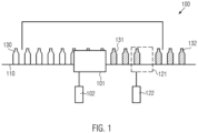
- Fig.1 shows a container treatment machine 100 according to the invention according to an embodiment, as it can be used in the packaging industry, in particular the beverage processing industry.
- the container treatment machine can be designed in various ways. In the embodiment shown here, it is designed as a linear container treatment machine, which comprises a transport device 110, which transports containers 130 through the container treatment machine.
- This can be a conveyor belt or other devices for transporting the containers.
- a transport device can also be provided that transports the containers in a hanging manner.
- a transport device can lead through the container treatment machine, which comprises a series of holders that hold the containers in the area of the usually provided support ring, for example with the help of clamps.
- the containers can be rotated by the holders.
- a series of turntables can be provided together with associated centering devices, which are guided through the container treatment system.
- an embodiment of the container treatment machine 100 is particularly advantageous which comprises a carousel as a transport device, on the periphery of which the turntables and centering devices are arranged.
- transport devices that transport the containers in a hanging manner can also be considered here.
- a device 101 is provided in the area of the container treatment machine, which can apply a functional layer to the containers 130 so that they are coated. These containers then emerge from the container treatment machine 100 as containers 131.
- the containers can be containers. These can consist of PET or include PET, for example. Other plastics used for containers in the packaging industry can also be used here. Furthermore, treatment of glass containers or metal containers according to the invention is also possible.
- a further container treatment unit 121 can be provided in the container treatment machine, which supplies the containers to a further treatment step (for example the application of printing ink or the like), so that the processed containers 132 are produced from the containers 131 initially provided only with the functional layer, which can then be removed from the container treatment machine.
- a further treatment step for example the application of printing ink or the like
- the device 101 can be assigned several additional devices 102, for example a control unit or a storage container in which material that is to serve as a precursor is kept in gaseous or liquid form.
- the device 101 is generally designed such that it can dispense the precursor material and additionally ensures that the precursor material is deposited in the form of a layer on the surface of the containers 130 and bonds with the surface of the containers through chemical reactions.
- Particularly preferred materials are those based on silicon that form a silicon oxide layer on the surface of the containers 130.
- Other materials including organic compounds or organometallic compounds that are organic compounds with a metallic component, are also possible here. Titanium-based compounds or generally silicon-containing compounds can also be used as precursors.
- no intentional oxidation of the container material and in particular of the surface to which the precursor is to be applied takes place before the precursor is applied to the surface of the container.
- the parameters under which the precursor is applied to the surface of the container are selected in such a way that the precursor can form a permanent bond even with a surface of the container that has not been intentionally oxidized, so that the precursor or the The functional layer formed can form a permanent bond with the surface of the container and serve as a basis for the application of printing inks or similar.
- the amount of oxidizing oxygen and hydroxyl radicals in the flame can be adjusted according to the selected gas-air ratio. Furthermore, when using silicon-based precursors, sufficiently highly reactive, layer-forming silicon species can also be created in the flame (plasma). When it comes into contact with the surface of the container, the top (or top) molecular layer on the container surface forms carbonyl, carboxyl or hydroxyl groups, which chemically bond very well with the silicon species.
- the device 101 can be implemented in different ways, but flame pyrolysis devices and plasma nozzles are particularly preferred.
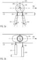
- the container treatment machine 100 comprises at least two flame pyrolysis devices 251 and 252 arranged on the same side of the transport device 110.
- the flame pyrolysis devices 251 and 252 are generally arranged such that they can apply flames 261 and 262 to a container 130 transported in the transport device 110 along the transport direction 295, so that the surface of the container is exposed to flame, i.e. is exposed to the flame.
- Contained in this flame or transported with it is the precursor material or the precursor, which forms bonds with the surface of the container, in particular due to the high thermal energy in the area of the flames 261 and 262, and thus builds up a functional layer on the surface of the container.
- the precursor can be supplied to the individual flame pyrolysis devices 251 and 252, for example, from the storage container (see reference numeral 102 in the Fig.1 ).
- the precursor material that is fed to the flame pyrolysis device 251 does not have to be identical to the precursor material that is fed to the flame pyrolysis device 252.
- the flame pyrolysis devices 251 and 252 can be arranged in any way, in particular at any distance from one another. According to the invention, they are only arranged in such a way that they are both arranged on the same side of the transport device and one after the other in the transport direction and can each apply flame to the surface of the container 130. For this purpose, they are preferably arranged at a distance d from the conveyor belt or from the surface of a container 130 transported therein, which is large enough that the flame generated by the respective flame pyrolysis device can apply flame to the surface of the container. Typical distances are in the range of a few cm, up to 15 cm.
- the flame pyrolysis devices 251 and 252 are beveled with respect to a plane 290 which is perpendicular to the transport direction 295, so that they enclose the angle ⁇ for the flame pyrolysis device 251 and the angle ⁇ for the flame pyrolysis device 252. These angles are measured in the plane shown here, i.e. in a plane parallel to the transport plane defined by the transport direction 295. When using a conveyor belt for the containers, this transport plane corresponds exactly to the plane defined by the conveyor belt.
- angles ⁇ and ⁇ can be chosen as appropriate. However, it is particularly advantageous if the discharge directions (also called exit directions) of the flames 261 and 262, which are ultimately defined by the angles ⁇ and ⁇ , are designed in such a way that both directions cross each other, as is shown in Fig. 2a is shown.
- the intersection point of the two directions can be selected at any point relative to the transport device. However, it is preferred if the intersection point is not in the area in which the flames also hit the surface of the container.
- the ratio between the distance e of the outlet openings in the flame pyrolysis devices 251 and 252 to the distance d (more precisely to the projection of the distance d in the plane perpendicular to the transport direction) between the surface of the container 130 (or to the edge of the transport device 110) and the Outlet openings in the flame pyrolysis devices 251 and 252 preferably such that e 2 d ⁇ tan ⁇ 2 .
- Fig. 2b shows an alternative embodiment in which the flame pyrolysis devices 251 and 252 are arranged in such a way that the exit directions of the flames from the flame pyrolysis devices 251 and 252 are parallel to each other, but the flame pyrolysis devices are optionally arranged at a distance L perpendicular to the transport direction.
- the flame pyrolysis devices are also arranged one after the other in the transport direction 295.
- An embodiment is preferred here in which the first flame pyrolysis device 251 in the transport direction is arranged closer to the transport device by the distance L than the flame pyrolysis device 252 following in the transport direction. This design allows the surface of the container 130 to be intensively exposed to flames by the flame 261.
- the statistical distribution of the precursor molecules forming the functional layer can be subject to significant fluctuations due to the high concentration near the discharge opening from the flame pyrolysis device 251, deviations in the layer thickness can occur here. These can also lead to a layer thickness of the functional layer that is less than a minimum layer thickness.
- the flame pyrolysis device 252 following in the transport direction, which is arranged at a greater distance from the surface of the container, can bring about a more uniform distribution of precursor material on the surface, so that at least deviations in the layer thickness such that the resulting layer thickness is less than a minimum layer thickness are avoided.
- the flow rate or concentration of precursor material in the second flame 262 can also be controlled so that the layer thickness that forms on the surface of the container through the second flame alone corresponds to 50% or even 75% of the minimum layer thickness.
- the flame pyrolysis devices 251 and 252 can be spaced apart from one another in such a way that they do not cause different areas of the surface of the container 130 to be exposed to flames at the same time.
- the distance between the first flame pyrolysis device 251 and the second flame pyrolysis device 252 can be 15 cm to 30 cm or more, so that the surface of the container is first exposed to flames by the first flame pyrolysis device 251 and the container is then transported further without being exposed to flames. During this time, the surface of the container can cool down briefly so that its temperature drops and carbonization caused by exposure to the second flame pyrolysis device 252 is avoided.
- the embodiment according to the Fig. 2b also allows the use of different precursor materials to form a two-layer system of functional layers such that a first layer consisting of a first precursor material is applied by the first flame pyrolysis device and a second precursor material is applied by the second flame pyrolysis device 252, which forms a second functional layer over the first functional layer.
- This embodiment can form a gradient in the layer structure with regard to certain chemical or physical properties, starting from the surface to the last functional layer, before a print layer or the like is applied.
- This embodiment is not limited to just two functional layers, but can also include the application of several functional layers with different thicknesses and/or in different areas of the surface of the container.
- two further flame pyrolysis devices 271 and 272 are provided, which are arranged on the opposite side of the transport device with respect to the container.
- the flame pyrolysis devices 251, 252 and 271 and 272 are shown as basically mirrored on a plane defined by the transport direction 295. This means in particular that in the embodiment shown, the flame pyrolysis devices 252 and 272 arranged in the transport direction of the container flow are each further away from the transport device than the flame pyrolysis devices 251 and 271 arranged first in the transport direction.
- the flame pyrolysis devices can also be arranged at the same distance as in the previously described embodiments and do not have to be arranged parallel to each other with respect to the direction of the flames.
- Flame pyrolysis devices 251 and 252, as well as 271 and 272 can also be used analogously to Fig. 2a The angles that the respective flame pyrolysis devices form with each other do not have to be the same, but can differ for the devices 251 and 252 from those of the devices 271 and 272.
- the flame pyrolysis devices can also be arranged offset from one another in the transport direction.
- the arrangements of the flame pyrolysis devices on one side of the transport device are simply mirrored on the other side of the transport device. All with reference to Fig. 2c
- the embodiments described can be used as appropriate to ensure either a faster and more uniform treatment or also special treatments. This can be particularly advantageous for containers that are not rotationally symmetrical or do not have at least one axis of symmetry (generally non-round containers).
- flame pyrolysis devices can also be arranged one above the other (perpendicular to the transport plane of the containers in the transport device). These can either have identical discharge directions and/or different discharge directions from one another. This can be achieved, for example, by tilting the flame pyrolysis devices against one another.
- the discharge directions of flame pyrolysis devices in a first plane can differ from those in a second plane.
- This embodiment is compatible with any of the Fig. 2a to 2c described variants.
- each of the variants can be combined in Fig. 2a to 2c be understood as a representation of a plane of flame pyrolysis devices, with further planes of flame pyrolysis devices emerging from the image plane also corresponding to embodiments according to Fig. 2a to 2c possible are.
- the flame pyrolysis devices arranged in a direction perpendicular to the transport direction can simultaneously flame different areas of the container, in particular areas at different heights (measured with respect to a transport plane in which the containers are transported), in order to deposit the functional layer.
- Fig.3 shows a further embodiment in which a plasma nozzle is used to apply the precursor to a container and to apply a functional layer to the surface of the container.
- the plasma nozzle 341 which preferably also comprises a dosing device for precursor material for forming the functional layer, is arranged such that it can apply a plasma 342, which at least also comprises the precursor material, to the surface 130 of the container moved along in a transport device in front of the plasma nozzle 341.
- the transport device in this embodiment is formed at least by a base plate 343 on which the container is arranged standing.
- each base plate 343 is assigned a centering device (not shown here), for example in the form of clamps, which can grip the container on the support ring or another area and thus stabilize it.
- the plate 343 is designed as a rotary plate so that it can rotate the container 130 on the plate 343 about the rotation axis R, which can preferably coincide with the longitudinal axis of the container.
- the precursor can thus be applied to the entire circumference of the container 130 by the plasma nozzle 341.
- the plasma nozzle 341 is mounted comparatively close to the surface of the container (a few mm to a few cm), the area over which the plasma 342 can be applied to the container 130 in the longitudinal direction by the plasma nozzle 341 only extends to a small section in the longitudinal direction, which corresponds to the extent of the dispersion of the plasma 342 after leaving the plasma nozzle 341.
- the entire surface of the container with a typical length of at least 7 cm, in particular approximately 10 mm to 200 mm and rarely even more, in the direction of the axis of rotation should be coated with the precursor material, it can be provided that in addition to the rotation, a translational movement is also carried out parallel to the axis of rotation R. This translational movement can either be carried out by the container on the turntable 343 (for example in cooperation with a suitable centering device) or the plasma nozzle 341 can be moved parallel to the axis of rotation. Combinations of these are also conceivable.
- plasma nozzles 341 can be arranged one after the other in the transport direction, each of these plasma nozzles applying plasma to the surface of the container in order to form a functional layer.
- each of the nozzles only coats a certain angular range, but the entire length of the container with plasma, or each of the nozzles applies the functional layer along the entire circumference during a full rotation of the container about its axis of rotation R , but only applies the plasma to a certain area in the longitudinal direction (i.e. parallel to the axis of rotation). It can also be provided that there is an overlap between the areas coated by the individual plasma nozzles, so that at least no area remains on the surface of the container that has not been coated with a plasma.
- the application of plasma to the surface of the container with an overlap can also be achieved by a plasma nozzle alone.
- the plasma nozzle can apply plasma to a first area (in the longitudinal and/or rotational direction) and then to a second area that partially overlaps the first.
- the plasma nozzle 341 can be moved in several spatial directions, in particular "back and forth” in the illustrated double arrow direction 344, so that it can be moved towards the container 130 or away from the container 130. Tilting the plasma nozzle 341 along the double arrow 345 (i.e. tilting in a plane perpendicular to the transport direction) can also be provided in order to reliably reach areas of the container that are curved in the longitudinal direction.
- a control unit can be provided which controls suitable alignment means for aligning and/or moving the plasma nozzle 341 depending on the shape of the container 130 such that the distance of the plasma nozzle 341 to the surface of the container 130 is constant, while the container 130 is rotated relative to the plasma nozzle 341 about the axis of rotation R and/or is moved parallel to the axis of rotation R.
- a distance sensor for example a laser diode or a similar optical sensor, can be provided to determine the distance. It can also be provided that data about the container shape stored in a memory assigned to the container treatment machine, for example, is used to determine how large the distance is between the surface of the container and the plasma nozzle at a certain position of the container. In addition or alternatively, a 3D scanning process can be used to determine the position and/or shape and/or current dimensions of the container and thus the distance to the plasma nozzle, either once when the container is transferred to the container treatment machine or several times, possibly even continuously.
- the plasma emitted by the plasma nozzle 341 is a low-temperature plasma.
- an area in the container treatment machine in which the container is exposed to plasma has a negative pressure, in particular a vacuum with a pressure of less than 10 -4 bar. In this way, the dispersion of the plasma emitted by the plasma nozzle 341 can be reduced.
- an electrode is introduced inside the container 130 and the plasma nozzle 341 functions as a counter electrode, so that a potential difference arises between the electrode introduced into the container 130 and the plasma nozzle 341 and the surface of the container is polarized, wherein the polarization is selected such that at least the precursors contained in the plasma experience an acceleration in the direction of the surface of the container 130. If the precursors contained in the plasma are negatively charged, for example, the surface of the container and thus the electrode in the container 130 should be positive in order to attract the precursor. Accordingly, the electrode is negatively charged if the precursor in the plasma 342 is positively charged.
- the plasma nozzles used in the invention can be plasma nozzles that are already commercially available. Since these can be operated in accordance with the method described, no or only minor structural modifications to such plasma nozzles are necessary in order to use them together with the method according to the invention.
- the containers can be moved in the transport plane perpendicular to the transport direction and perpendicular to a provided axis of rotation R in a direction s, so that the distance of the surface of the container, which is either exposed to flame by the flame pyrolysis device or is exposed to plasma by the plasma nozzle, to the flame pyrolysis device or the plasma nozzle is constant.
- This is particularly advantageous for non-round containers, as it can prevent unwanted collisions with the flame pyrolysis devices and the plasma nozzles, but also excessive heating, especially when using flame pyrolysis devices.
- a distance of the container to the flame pyrolysis device or to the plasma nozzle is preferably determined in a starting position. If the containers are clamped by a base plate and a centering device or held by brackets, this determination can be replaced by a value stored in an internal memory of the container treatment machine or a control unit assigned to it. The movement of the container in direction s is then controlled such that the distance k of the surface of the container to the flame pyrolysis device and/or the plasma nozzle is constant.
- This movement ensures that a point on the surface that is currently being acted upon by the flame pyrolysis device or the plasma nozzle always has the specified distance k to the flame pyrolysis device or the plasma nozzle.
Landscapes
- Engineering & Computer Science (AREA)
- Manufacturing & Machinery (AREA)
- Chemical & Material Sciences (AREA)
- Combustion & Propulsion (AREA)
- Details Of Rigid Or Semi-Rigid Containers (AREA)
- Plasma Technology (AREA)
Description
- Die vorliegende Erfindung betrifft ein Verfahren zum Behandeln einer Oberfläche eines Behälters gemäß Anspruch 1 und eine Behälterbehandlungsmaschine zum Behandeln einer Oberfläche eines Behälters gemäß Anspruch 9.
- In der Verpackungsindustrie, insbesondere in der getränkeverarbeitenden Industrie kommen häufig Behälter auf Kunststoffbasis, insbesondere PET und andere Materialien wie Glas oder Metall, zum Einsatz. Soll die äußere Oberfläche dieser Behälter bedruckt oder anderweitig bearbeitet werden, muss sichergestellt werden, dass die aufzubringenden Materialien auch an der Oberfläche des Behälters haften. Da die Eigenschaften (physikalisch und/oder chemisch) der Oberfläche von Behältern abhängig vom verwendeten Material sind und auch bei einem gegebenen Behälter nicht homogen sind, wurden in der Vergangenheit verschiedene Möglichkeiten angegeben, die Eigenschaften der Oberfläche des Behälters mit Hinblick auf eine Benetzung mit Drucktinten oder anderen Materialien zu verbessern.
- So schlägt die
EP 2 089 234 B1 ein Verfahren vor, bei dem auf den Behälter zunächst eine Grundierung und dann ein Druckbild mit Hilfe digitaler Techniken aufgebracht wird. Die Grundierung kann zur Verbesserung der Hafteigenschaften der darauf aufgebrachten Drucktinte vorgegeben sein. - Es erweist sich jedoch als problematisch, dass auch die Grundierung auf der Oberfläche des Behälters haften muss und ihre Zusammensetzung daher abhängig vom Behältermaterial ist, was auch Einfluss auf die Hafteigenschaften der auf die Grundierung aufgebrachten Drucktinte haben kann.
- Andererseits schlägt die
EP 1 148 036 B1 vor, die Oberfläche eines Behälters zunächst mit Hilfe von Brennern zu oxidieren und anschließend eine haftvermittelnde Funktions-Schicht auf die oxidierte Oberfläche mittels Flammenpyrolyse aufzubringen, wobei hierbei insbesondere siliziumhaltige Materialien zum Einsatz kommen. Aufgrund der vielen unterschiedlichen Verfahrensschritte, die zur Vorbehandlung der Oberfläche des Behälters nötig sind, wird die Vorbehandlung des Behälters komplex und ist darüber hinaus ebenfalls stark abhängig von dem zugrundeliegenden Behältermaterial. Außerdem besteht bei diesen Verfahren die Gefahr, dass die Behälteroberfläche Verkohlungen erleidet. - Weiterhin sind inzwischen Verfahren bekannt, bei denen Oberflächen, insbesondere Kunststoffoberflächen mittels eines reinen atmosphärischen Plasmas behandelt werden. Das Plasma tritt dabei als verformter Bogen aus einer Düse aus. Die räumliche Ausdehnung des Plasmastrahls senkrecht zur Bewegungsrichtung ist üblicherweise klein, sodass die Oberfläche in mehreren Abschnitten behandelt werden muss. Weiterhin ist bei diesem Verfahren bisher problematisch, dass die Behälter konturiert sind, also eine von einer im wesentlichen glatten Oberfläche abweichende Oberflächenform (beispielsweise mit Rillen) aufweisen. Da der Plasmastrahl nur eine geringe Schärfentiefe bzw. Wirkbreite besitzt, war bisher nur das Behandeln von Behältern mit glatter Oberfläche im Wesentlichen ohne Konturierung möglich.
- Die
JP 2018 024559 A - Die Erfindung der
EP 2 799 241 A2 betrifft ein Verfahren und eine Vorrichtung zum Direktbedrucken von Kunststoffbehältern, wobei in einem ersten Schritt eine Zwischenschicht mit Hilfe einer ersten Vorrichtung auf den zu bedruckenden Behälter aufgebracht wird und in einem zweiten Schritt der Behälter in bestimmten Bereichen mit Hilfe einer zweiten Vorrichtung bedruckt wird, dadurch gekennzeichnet, dass die Zwischenschicht eine Verbindung mit dem Behälter und der Druckschicht eingeht, die unlöslich in wässrigen Lösungen mit einem pH-Wert zwischen 3 und 10 und gut löslich in wässrigen Lösungen mit einem pH-Wert in einem Bereich kleiner als 3 und/oder größer als 10 ist; und ein Recyclingverfahren für einen mit einer Zwischenschicht versehenen Kunststoffbehälter. - In der
US 10 016 997 B1 - Die
DE 10 2013 110125 A1 offenbart ein Verfahren und eine Vorrichtung zur Oberflächenvorbehandlung eines dreidimensionalen Körpers zur Vorbereitung einer dreidimensionalen Oberfläche des Körpers für ein Bedrucken, bei dem die zu bedruckende Oberfläche zur Säuberung und/oder zur Anpassung an die Oberflächenspannung des Druckmaterials relativ zu einer Oberflächenbehandlungseinrichtung bewegt wird, um die gesamte zu bedruckende Oberfläche zu behandeln. Dabei ist vorgesehen, dass der dreidimensionale Körper in einer Transportstrecke einer Transporteinrichtung der Oberflächenbehandlung unterzogen wird. - Die
DE 10 2013 215637 A1 beschreibt eine Vorrichtung zum Bedrucken von Behältern, umfassend wenigstens eine Transportstrecke in der Behälter transportiert werden können und eine Vielzahl von Druckmodulen zum Bedrucken der Behälter, dadurch gekennzeichnet, dass wenigstens zwei Druckmodule Digitaldruckmodule sind und sich hinsichtlich ihrer Digitaldrucktechnik unterscheiden und ein entsprechendes Verfahren. - Ausgehend vom bekannten Stand der Technik besteht die zu lösende technische Aufgabe daher darin, ein Verfahren und eine Behälterbehandlungsmaschine anzugeben, die eine Verbesserung der Benetzbarkeit der Oberfläche eines Behälters erreichen, jedoch gleichzeitig weniger spezielle Ansprüche hinsichtlich der Komplexität des durchgeführten Verfahrens bzw. der Behälterbehandlungsmaschine stellen.
- Diese Aufgabe wird erfindungsgemäß durch das Verfahren nach Anspruch 1 und die Behälterbehandlungsmaschine zum Behandeln einer Oberfläche eines Behälters nach Anspruch 9 gelöst. Vorteilhafte Weiterbildungen der Erfindung sind in den Unteransprüchen erfasst.
- Das erfindungsgemäße Verfahren zum Behandeln einer Oberfläche eines Behälters, wie einer Flasche, in der Verpackungsindustrie umfasst, dass auf eine nicht oxidierte Oberfläche des Behälters in einer Behälterbehandlungsmaschine eine Funktions-Schicht aufgebracht wird.
- Die Funktions-Schicht ist eine Schicht, die auf die Oberfläche des Behälters aufgebracht wird, bevor der Behälter mit einem Druckbild oder überhaupt Drucktinte benetzt wird. Das Aufbringen der Funktions-Schicht umfasst dabei keine Verfahren, die einen digitalen Druck einer solchen Funktions-Schicht erfordern.
- Die nicht oxidierte Oberfläche des Behälters ist als solche Oberfläche zu verstehen, die nicht in einem vorangegangenen Verfahrensschritt durch eine oxidierende Flamme oder andere Verfahren, die die Molekülgruppen an der Oberfläche des Behälters oxidieren würden, behandelt wurde.
- Wird die Funktions-Schicht auf eine solche nicht oxidierte Oberfläche aufgebracht, können vorangestellte Verfahrensschritte, die die Oberfläche des Behälters bereits oxidieren oder anderweitig bearbeiten, ausgelassen werden, sodass das gesamte Verfahren weniger komplex ist, jedoch gleichzeitig durch die Bildung der Funktions-Schicht auf der Oberfläche des Behälters eine gute Benetzbarkeit durch Drucktinten gewährleistet wird. Insbesondere kann so erreicht werden, dass eine einheitliche Funktions-Schicht auf verschiedenste Substrate aufgebracht wird, womit eine für alle Behältersorten (Substrate) einheitliche, bedruckbare Oberfläche geschaffen wird. Der Entwicklungsaufwand für Druckfarben, die auf verschiedensten Substraten angewendet werden können, kann somit ganz entfallen oder zumindest erheblich reduziert werden.
- Das Aufbringen der Funktions-Schicht erfolgt mittels Flammenpyrolyse, wobei ein bevorzugt gasförmiger Precursor der Flamme beigemischt wird, der auf und/oder mit der Oberfläche des Behälters die Funktions-Schicht bildet.
- In einer Ausführungsform umfasst die Behälterbehandlungsmaschine zwei Flammenpyrolyse-Einrichtungen, wobei die nicht oxidierte Oberfläche des Behälters bei Anwesenheit eines Precursors beflammt wird und die Funktions-Schicht zumindest in dem Bereich auf der nicht oxidierten Oberfläche aufgebracht wird, der von den Flammenpyrolyse-Einrichtungen beflammt wird. Der beflammte Bereich der Oberfläche ist dabei der Bereich, der unmittelbar mit der von den Flammenpyrolyse-Einrichtungen erzeugten Flamme in Kontakt steht.
- Der Precursor ist in dieser Ausführung als Gas oder Tröpfchen in die Flamme oder die Flammenpyrolyse-Einrichtungen selbst einbringbar, sodass er in dem Bereich der Flamme auch auf die Oberfläche des Behälters trifft und dort durch chemische Reaktionen auf der Oberfläche eine haftende Funktions-Schicht bildet. Dabei versteht es sich, dass der ursprünglich in die Flamme eingebrachte Precursor chemisch nicht mehr identisch zu dem Material, das die "Funktions-Schicht" bildet, sein muss. In jedem Fall wird die Funktions-Schicht jedoch zumindest zum Teil durch den Precursor gebildet.
- Die erfindungsgemäße Ausführungsform umfasst zwei Flammenpyrolyse-Einrichtungen und die Behälter werden in einer Transporteinrichtung transportiert, die die Behälter an den Flammenpyrolyse-Einrichtungen in Transportrichtung vorbei transportiert, wobei die Flammenpyrolyse-Einrichtungen in Transportrichtung nacheinander angeordnet sind und die nicht oxidierte Oberfläche des Behälters nacheinander beflammen, wobei die Flammenpyrolyse-Einrichtungen so ausgerichtet sind, dass eine erste Flammenpyrolyse-Einrichtung die Flamme in eine erste Richtung ausbringt und eine zweite Flammenpyrolyse-Einrichtung die Flamme in eine zweite Richtung ausbringt. Da der Beflammung mit dem Precursor vorgeschaltete Oxidationsprozesse entfallen, kann durch diese Ausführungsform ein möglichst schnelles Beflammen der Oberfläche des Behälters mit dem Precursor erfolgen, wobei gleichzeitig die Schichtdicke der Funktions-Schicht vorteilhaft eingestellt und vergrößert werden kann.
- Es kann vorgesehen sein, dass die Behälterbehandlungsmaschine eine Plasmadüse umfasst, wobei die Oberfläche des Behälters mit einem den Precursor enthaltenden Plasma beaufschlagt wird und die Funktions-Schicht zumindest in dem Bereich auf der nicht oxidierten Oberfläche aufgebracht wird, die von der Plasmadüse mit dem Plasma beaufschlagt wird.
- Bei dem Plasma handelt es sich bevorzugt um ein Niedertemperaturplasma. Durch die Verwendung von Plasma bei niedrigerer Temperatur kann die Funktions-Schicht praktisch zerstörungsfrei auf der Oberfläche des Behälters aufgebracht werden, wodurch versehentliche Beschädigungen und auch Verkohlungen der Oberfläche des Behälters vermieden werden können.
- In einer Weiterbildung dieser Ausführungsform ist vorgesehen, dass der Behälter entlang seiner Längsachse bewegt wird, während die Plasmadüse die Oberfläche des Behälters mit dem Plasma beaufschlagt. Da der Wirkungsbereich der Plasmadüse üblicherweise klein im Vergleich zu den Abmessungen der Oberfläche des Behälters ist, kann mit dieser Ausführungsform die Beaufschlagung der gesamten Oberfläche des Behälters realisiert werden.
- Weiterhin kann vorgesehen sein, dass der Behälter um eine Achse (insbesondere seine Längsachse) gedreht wird, während die Funktions-Schicht auf die nicht oxidierte Oberfläche aufgebracht wird. Auf diese Weise kann ferner eine Rundumbeschichtung mit der Funktions-Schicht erfolgen.
- Ferner kann vorgesehen sein, dass die Bewegung des Behälters relativ zur Plasmadüse so gesteuert wird, dass der Abstand der mit dem Plasma beaufschlagten Oberfläche von der Plasmadüse stets konstant oder im Wesentlichen konstant ist. Dies kann umfassen, dass der Behälter sowohl entlang einer Achse (insbesondere seiner Längsachse) bewegt wird und/oder (gleichzeitig) rotiert. Weiterhin kann der Behälter in einer Ebene senkrecht zu der Achse translatorisch bewegt werden, sodass beispielsweise der Abstand der Achse zur Plasmadüse verändert wird. Dies ist insbesondere bei nicht runden Behältern (Behältern mit nicht rundem Querschnitt) und konturierten Behältern vorteilhaft, auch um Kollisionen mit der Plasmadüse zu vermeiden.
- Dass der Abstand der Oberfläche zur Plasmadüse nur "im Wesentlichen" konstant ist bedeutet, dass insbesondere bei Embossings oder erhabenen Texten auf der Oberfläche des Behälters oder Erhebungen/Vertiefungen auf der Oberfläche, die nur eine geringe räumliche Ausdehnung besitzen, eine Anpassung des Abstands zwischen Oberfläche und Behälter nicht erfolgt sofern die Ausdehnung dieser Erhebungen/Vertiefungen, Ebmossings, erhabenen Texte in Richtung der Plasmadüse wesentlich kleiner ist als der Abstand der übrigen Oberfläche zur Plasmadüse (beispielsweise kleiner als 20% oder kleiner als 10% oder kleiner als 2% als der Abstand zwischen der übrigen Oberfläche und der Plasmadüse).
- In einer Ausführungsform ist vorgesehen, dass der Abstand der nicht oxidierten Oberfläche, die von der Flammenpyrolyse-Einrichtung beflammt wird, oder die von der Plasmadüse mit Plasma beaufschlagt wird, zur Flammenpyrolyse-Einrichtung oder zur Plasmadüse konstant bleibt, während der Behälter relativ zur Flammenpyrolyse-Einrichtung oder zur Plasmadüse gedreht wird. Bei nicht runden Behältern kann so sichergestellt werden, dass das Aufbringen der Funktions-Schicht über die gesamte Oberfläche unter möglichst gleichen Bedingungen erfolgt.
- Der Precursor kann weiterhin wenigstens eines von Silizium, metallorganische Verbindungen, Titan, siliziumhaltige Verbindungen umfassen. Diese können zuverlässig auf der Oberfläche von Behältern aufgebracht werden und können dessen Eigenschaften bezüglich Benetzung mit Drucktinten positiv beeinflussen.
- Die erfindungsgemäße Behälterbehandlungsmaschine zum Behandeln einer Oberfläche eines Behälters, wie einer Flasche, in der Verpackungsindustrie, umfasst eine Transporteinrichtung zum Transportieren der Behälter entlang einer Transportrichtung und zwei Flammenpyrolyse-Einrichtungen, die angeordnet und ausgebildet sind, eine Oberfläche eines Behälters, der in der Transporteinrichtung transportiert wird, zu beflammen und eine Funktions-Schicht aufzubringen und ist dadurch gekennzeichnet, dass die Flammenpyrolyse-Einrichtungen beide auf derselben Seite der Transporteinrichtung angeordnet sind und wobei die Flammenpyrolyse-Einrichtungen in Transportrichtung nacheinander angeordnet und so ausgerichtet sind, dass eine erste Flammenpyrolyse-Einrichtung die Flamme in eine erste Richtung ausbringt und eine zweite Flammenpyrolyse-Einrichtung die Flamme in eine zweite Richtung ausbringt.
- Diese spezielle Anordnung der Flammenpyrolyse-Einrichtungen erleichtert den Zugang zu denselben und vereinfacht auch die Konstruktion der für das Einbringen des Precursors in die Flammen notwendigen Leitungen, da diese nicht um die gesamte Behälterbehandlungsmaschine herum geführt werden müssen, sondern lediglich auf einer Seite vorgesehen sein müssen.
- Es versteht sich, dass die erste Richtung und die zweite Richtung zumindest so vorgesehen sein müssen, dass die Flamme in Richtung der Transporteinrichtung so ausgebracht wird, dass ein in ihr befindlicher Behälter, der an den Flammenpyrolyse-Einrichtungen vorbei transportiert wird, auch durch die Flammen beflammt werden kann. Durch die Anordnung der Flammenpyrolyse-Einrichtungen auf diese Weise kann sichergestellt werden, dass auch die gesamte Oberfläche des Behälters beflammt, bevorzugt homogen beflammt wird.
- In einer Weiterbildung dieser Ausführungsform sind die erste Richtung und die zweite Richtung parallel zueinander. Diese Ausführungsform erlaubt gleichzeitig unterschiedliche Bereiche eines an den Flammenpyrolyse-Einrichtungen vorbei bewegten Behälters zu beflammen, was die Gesamtdauer zum Aufbringen einer Funktions-Schicht mit vorgegebener Dicke reduzieren kann.
- In einer Weiterbildung ist vorgesehen, dass die erste und zweite Flammenpyrolyse-Einrichtung verschiedene Abstände zur Transporteinrichtung besitzen. Dies kann insbesondere beim Beflammen von Behältern mit nicht rundem Querschnitt vorteilhaft sein.
- In einer alternativen Ausführungsform ist vorgesehen, dass die erste und zweite Richtung einen Winkel α miteinander einschließen, der gegeben ist durch α = β + γ, wobei β und γ die von der ersten und der zweiten Richtung mit einer Ebene senkrecht zur Transportrichtung eingeschlossenen Winkel sind. Unterschiedliche Anforderungen mit Hinblick auf das Beflammen der Oberfläche des Behälters können so realisiert werden.
- In einer Weiterbildung dieser Ausführungsform ist


- Weiterhin kann vorgesehen sein, dass die Transporteinrichtung eine Drehvorrichtung umfasst, die ausgebildet ist, einen von der Transporteinrichtung transportierten Behälter während der Beaufschlagung durch die Flammenpyrolyse-Einrichtungen so zu drehen, dass der Abstand der mit der Flamme beaufschlagten Oberfläche von der Flammenpyrolyse-Einrichtung stets gleich ist. Damit können die geometrischen Eigenschaften beim Beaufschlagen der Behälter mit der Funktions-Schicht auch bei nicht runden Behältern konstant bleiben.
- Es kann alternativ auch eine Behälterbehandlungsmaschine vorgesehen sein, die eine Transporteinrichtung zum Transportieren der Behälter entlang einer Transportrichtung und eine Plasmadüse umfasst, wobei die Plasmadüse ausgebildet ist, eine nicht oxidierte Oberfläche des Behälters mit einem einen Precursor enthaltenden Plasma zu beaufschlagen, um eine Funktions-Schicht auf der Oberfläche des Behälters abzuscheiden.
-
- Fig. 1
- schematische Darstellung einer Behälterbehandlungsmaschine gemäß einer Ausführungsform
- Fig. 2a-c
- schematische Darstellung verschiedener Ausführungsformen mit Flammenpyrolyse-Einrichtungen
- Fig. 3
- schematische Darstellung einer Ausführungsform mit Plasmadüse
-
Fig. 1 zeigt eine erfindungsgemäße Behälterbehandlungsmaschine 100 gemäß einer Ausführungsform, wie sie in der Verpackungsindustrie, insbesondere der getränkeverarbeitenden Industrie zum Einsatz kommen kann. Die Behälterbehandlungsmaschine kann auf diverse Weisen ausgebildet sein. In der hier dargestellten Ausführungsform ist sie als linear arbeitende Behälterbehandlungsmaschine ausgebildet, die eine Transporteinrichtung 110 umfasst, welche Behälter 130 durch die Behälterbehandlungsmaschine transportiert. Dabei kann es sich um ein Förderband oder andere Einrichtungen zum Transport der Behälter handeln. Anstelle eines Transportbandes kann auch eine Transporteinrichtung vorgesehen sein, die die Behälter hängend transportiert. Beispielsweise kann eine Transporteinrichtung durch die Behälterbehandlungsmaschine führen, die eine Reihe von Halterungen umfasst, die die Behälter im Bereich des üblicherweise vorgesehenen Tragrings beispielsweise mit Hilfe von Klammern halten. In diesem Fall kann vorteilhaft auch vorgesehen sein, dass die Behälter von den Halterungen gedreht werden können. - Alternativ kann auch eine Reihe von Drehtellern zusammen mit ihnen zugeordneten Zentriereinrichtungen vorgesehen sein, die durch die Behälterbehandlungsanlage geführt werden. In einem solchen Fall ist eine Ausführungsform der Behälterbehandlungsmaschine 100 besonders vorteilhaft, die als Transporteinrichtung ein Karussell umfasst, an dessen Peripherie die Drehteller und Zentriereinrichtungen angeordnet sind. Anstelle der Drehteller und Zentriereinrichtungen kommen aber auch hier Transporteinrichtungen in Betracht, die die Behälter hängend transportieren.
- In jedem Fall ist erfindungsgemäß eine Vorrichtung 101 im Bereich der Behälterbehandlungsmaschine vorgesehen, die eine Funktions-Schicht auf die Behälter 130 aufbringen kann, sodass sie beschichtet werden. Diese Behälter treten danach als Behälter 131 aus der Behälterbehandlungsmaschine 100 aus. Bei den Behältern kann es sich um Behälter handeln. Diese können beispielsweise aus PET bestehen oder dieses umfassen. Auch andere in der Verpackungsindustrie verwendete Kunststoffe für Behälter können hier zum Einsatz kommen. Ferner ist auch eine Behandlung von Glasbehältern oder metallischen Behältern entsprechend der Erfindung möglich.
- Optional kann eine weitere Behälterbehandlungseinheit 121 in der Behälterbehandlungsmaschine vorgesehen sein, die die Behälter einem weiteren Behandlungsschritt (beispielsweise das Aufbringen von Drucktinte oder Ähnliches) zuführt, sodass aus den zunächst nur mit der Funktions-Schicht versehenen Behältern 131 die bearbeiteten Behälter 132 hergestellt werden, die anschließend aus der Behälterbehandlungsmaschine abgeführt werden können.
- Der Vorrichtung 101 können mehrere zusätzliche Einrichtungen 102 zugeordnet sein, beispielsweise eine Steuereinheit oder ein Vorlagebehälter, in dem Material, das als Precursor dienen soll, in gasförmiger oder flüssiger Form vorgehalten wird. Die Vorrichtung 101 ist allgemein so ausgebildet, dass sie das Precursor-Material ausbringen kann und zusätzlich erreicht wird, dass sich das Precursor-Material in Form einer Schicht auf der Oberfläche der Behälter 130 absetzt und sich mit der Oberfläche der Behälter durch chemische Reaktionen verbindet.
- Besonders bevorzugt kommen hier Materialien zum Einsatz, die auf Silizium basieren und auf der Oberfläche der Behälter 130 eine Siliziumoxidschicht bilden. Auch andere Materialien, umfassend organische Verbindungen oder metallorganische Verbindungen, die organische Verbindungen mit einem metallischen Anteil darstellen, kommen hier in Betracht. Genauso können als Precursor Verbindungen auf Titanbasis oder allgemein siliziumhaltige Verbindungen vorgesehen sein.
- Erfindungsgemäß ist vorgesehen, dass vor dem Aufbringen des Precursors auf die Oberfläche des Behälters keine absichtliche Oxidation des Behältermaterials und insbesondere der Oberfläche, auf die der Precursor aufgebracht werden soll, erfolgt. Dazu zählt insbesondere, dass keine Oxidation der Oberfläche des Behälters stromauf der Vorrichtung 101 mit Hilfe von Flammeneinwirkung und von Sauerstoff erfolgt.
- Dazu werden die Parameter, unter denen der Precursor auf die Oberfläche des Behälters aufgebracht wird, so gewählt, dass der Precursor auch mit einer nicht absichtlich oxidierten Oberfläche des Behälters eine beständige Verbindung eingehen kann, sodass der Precursor bzw. die mit ihm gebildete Funktions-Schicht eine beständige Verbindung mit der Oberfläche des Behälters eingehen und als Grundlage für das Aufbringen von Drucktinten oder Ähnlichem dienen kann.
- Entsprechend dem gewählten Gas-Luft-Verhältnis kann die Menge des oxidierenden Sauerstoffs und der Hydroxyl-Radikale in der Flamme (bzw. wie unten beschrieben dem Plasma) eingestellt werden. Ferner können so bei Verwendung von siliziumbasierten Precursorn auch ausreichend hochreaktive, schichtbildende Siliziumspezies in der Flamme (dem Plasma) entstehen. Durch die Berührung mit der Oberfläche des Behälters bildet die oberste (oder die oberen) Molekülschicht auf der Behälteroberfläche Carbonyl-, Carboxyl-, bzw. Hydroxyl-Gruppen, die mit den Siliziumspezies sehr gut chemisch binden.
- Die Vorrichtung 101 kann unterschiedlich realisiert werden, besonders bevorzugt sind jedoch Flammenpyrolyse-Einrichtungen und Plasmadüsen.
- Dazu zeigen die
Fig. 2a - c Ausführungsformen, bei denen die Behälterbehandlungsmaschine 100 als konkrete Realisierung der Vorrichtung 101 wenigstens zwei, auf derselben Seite der Transporteinrichtung 110 angeordnete Flammenpyrolyse-Einrichtungen 251 und 252 umfasst. Die Flammenpyrolyse-Einrichtungen 251 und 252 sind allgemein so angeordnet, dass sie auf einen in der Transporteinrichtung 110 entlang der Transportrichtung 295 transportierten Behälter 130 Flammen 261 und 262 ausbringen können, sodass die Oberfläche des Behälters beflammt, also mit der Flamme beaufschlagt wird. In dieser Flamme enthalten bzw. mit ihr transportiert wird das Precursor-Material bzw. der Precursor, der insbesondere durch die hohe thermische Energie im Bereich der Flammen 261 und 262 Verbindungen mit der Oberfläche des Behälters eingeht und somit eine Funktions-Schicht auf der Oberfläche des Behälters aufbaut. Der Precursor kann den einzelnen Flammenpyrolyse-Einrichtungen 251 und 252 beispielsweise aus dem Vorlagebehälter (siehe Bezugszeichen 102 in derFig. 1 ) zugeführt werden. Das Precursor-Material, das der Flammenpyrolyse-Einrichtung 251 zugeführt wird, muss dabei nicht identisch zu dem Precursor-Material sein, das der Flammenpyrolyse-Einrichtung 252 zugeführt wird. - Grundsätzlich können die Flammenpyrolyse-Einrichtungen 251 und 252 beliebig, insbesondere beliebig beabstandet zueinander angeordnet sein. Sie sind erfindungsgemäß lediglich so angeordnet, dass sie beide auf derselben Seite der Transporteinrichtung und in Transportrichtung nacheinander angeordnet sind und jeweils ein Beflammen der Oberfläche des Behälters 130 realisieren können. Dazu sind sie bevorzugt in einem Abstand d zum Transportband bzw. zu der Oberfläche eines darin transportierten Behälters 130 angeordnet, der so groß ist, dass die von der jeweiligen Flammenpyrolyse-Einrichtung erzeugte Flamme die Oberfläche des Behälters beflammen kann. Typische Abstände liegen im Bereich einiger cm, bis zu 15 cm.
- So wird ein möglichst großer Bereich der Oberfläche des Behälters 130 durch die jeweilige Flammenpyrolyse-Einrichtung beflammt. Dies wiederum kann die gesamte zum Aufbringen der Funktions-Schicht auf der Oberfläche des Behälters benötigte Zeit reduzieren, wenn auch noch der Behälter um seine Rotationsachse R (hier senkrecht zur Bildebene verlaufend) gedreht wird, während er entlang der Transporteinrichtung transportiert wird. Abhängig von der vorgesehenen Schichtdicke, aber auch abhängig von der Transportgeschwindigkeit der Behälter in der Transporteinrichtung 110, kann entweder vorgesehen sein, dass die Behälter nicht in Transportrichtung 295 bewegt werden, sondern sie von den Flammenpyrolyse-Einrichtungen 251 und 252 beaufschlagt werden oder dass die Bewegung der Behälter 130 entlang der Transporteinrichtung 110 in Richtung 295 kontinuierlich erfolgt, während sie beispielsweise um ihre eigene Achse gedreht werden.
- In der in
Fig. 2a dargestellten Ausführungsform sind die Flammenpyrolyse-Einrichtungen 251 und 252 bezüglich einer Ebene 290, die senkrecht auf der Transportrichtung 295 steht, angeschrägt, sodass sie mit dieser den Winkel βfür die Flammenpyrolyse-Einrichtung 251 und den Winkel γ für die Flammenpyrolyse-Einrichtung 252 einschließen. Diese Winkel sind in der hier dargestellten Ebene gemessen, also in einer Ebene parallel zur durch die Transportrichtung 295 definierten Transportebene. Bei Verwendung eines Förderbandes für die Behälter entspricht diese Transportebene gerade der durch das Förderband definierten Ebene. - Die Winkel β und γ können nach Zweckmäßigkeit gewählt werden. Es ist jedoch besonders vorteilhaft, wenn die letztlich durch die Winkel β und γ definierten Ausbringrichtungen (auch Austrittsrichtungen genannt) der Flammen 261 und 262 so ausgebildet sind, dass sich beide Richtungen kreuzen, wie dies in
Fig. 2a dargestellt ist. - Insbesondere kann vorgesehen sein, dass der von den Ausbringrichtungen der Flammen 261 und 262 (hier gestrichelt dargestellt) eingeschlossene Winkel sich aus α = β + γ ergibt.
- Der Schnittpunkt der beiden Richtungen kann dabei relativ zu der Transporteinrichtung an einer beliebigen Stelle gewählt werden. Bevorzugt ist es jedoch, wenn der Schnittpunkt nicht in dem Bereich liegt, in dem die Flammen auch auf die Oberfläche des Behälters auftreffen. Dazu kann in einer besonders bevorzugten Ausführungsform vorgesehen sein, dass die Winkel β und γ gleich groß sind, sodass insbesondere


- So wird gewährleistet, dass der Schnittpunkt der Richtungen, in denen die Flammen aus den Flammenpyrolyse-Einrichtungen 251 und 252 austreten, entweder auf oder kurz hinter (in Bewegungsrichtung der Flammen) der Oberfläche des Behälters 130 liegt. Dies kann besonders dann von Vorteil sein, wenn durch die Flammenpyrolyse-Einrichtungen 251 und 252 unterschiedliche Materialien als Precursor ausgebracht werden, die zusammen auf der Oberfläche des Behälters eine beständige Funktions-Schicht bilden. In diesem Fall kann sichergestellt werden, dass eine möglicherweise erwünschte chemische Reaktion dieser beiden Materialien erst unmittelbar bei Auftreffen auf die Oberfläche des Behälters eintritt und damit in Anwesenheit des Behältermaterials erfolgt, was das Abscheiden der finalen Funktions-Schicht begünstigen kann.
-
Fig. 2b zeigt eine alternative Ausführungsform, bei der die Flammenpyrolyse-Einrichtungen 251 und 252 derart zueinander angeordnet sind, dass die Austrittsrichtungen der Flammen aus den Flammenpyrolyse-Einrichtungen 251 und 252 parallel zueinander sind, die Flammenpyrolyse-Einrichtungen jedoch gegebenenfalls in einem Abstand L senkrecht zur Transportrichtung angeordnet sind. Die Flammenpyrolyse-Einrichtungen sind ferner in Transportrichtung 295 nacheinander angeordnet. Bevorzugt ist hier eine Ausführungsform, bei der die in Transportrichtung erste Flammenpyrolyse-Einrichtung 251 um den Abstand L näher an der Transporteinrichtung angeordnet ist, als die in Transportrichtung folgende Flammenpyrolyse-Einrichtung 252. Durch diese Ausführung kann zunächst eine intensive Beflammung der Oberfläche des Behälters 130 durch die Flamme 261 erfolgen. Da die statistische Verteilung der die Funktions-Schicht bildenden Moleküle des Precursors aufgrund der hohen Konzentration in der Nähe der Ausbringöffnung aus der Flammenpyrolyse-Einrichtung 251 merklichen Schwankungen unterliegen kann, kann es hier zu Abweichungen in der Schichtdicke kommen. Diese können auch zu einer Schichtdicke der Funktions-Schicht führen, die geringer als eine Mindestschichtdicke ist. - Hierzu kann die in Transportrichtung nachfolgende Flammenpyrolyse-Einrichtung 252, die in größerem Abstand zur Oberfläche des Behälters angeordnet ist, eine gleichmäßigere Verteilung von Precursor-Material auf der Oberfläche bewirken, sodass zumindest Abweichungen in der Schichtdicke derart, dass die resultierende Schichtdicke geringer als eine Mindestschichtdicke ist, vermieden werden. Zu diesem Zweck kann auch die Durchflussmenge oder Konzentration von Precursor-Material in der zweiten Flamme 262 so gesteuert werden, dass allein durch die zweite Flamme die Schichtdicke, die sich auf der Oberfläche des Behälters bildet, 50 % oder gar 75 % der Mindestschichtdicke entspricht.
- Die Flammenpyrolyse-Einrichtungen 251 und 252 können derart beabstandet zueinander sein, dass durch sie nicht gleichzeitig ein Beflammen unterschiedlicher Bereiche der Oberfläche des Behälters 130 bewirkt wird. Insbesondere kann der Abstand zwischen der ersten Flammenpyrolyse-Einrichtung 251 und der zweiten Flammenpyrolyse-Einrichtung 252 15cm bis 30 cm oder mehr betragen, sodass zunächst ein Beflammen der Oberfläche des Behälters durch die erste Flammenpyrolyse-Einrichtung 251 erfolgt und anschließend der Behälter weiter transportiert wird, ohne dass ein Beflammen erfolgt. Während dieser Zeit kann ein kurzes Auskühlen der Oberfläche des Behälters erfolgen, sodass seine Temperatur sinkt und Verkohlungen durch das Beaufschlagen mit der zweiten Flammenpyrolyse-Einrichtung 252 vermieden werden.
- Die Ausführungsform gemäß der
Fig. 2b erlaubt auch den Einsatz verschiedener Precursor-Materialien zum Bilden eines Zwei-Schicht-Systems aus Funktions-Schichten derart, dass durch die erste Flammenpyrolyse-Einrichtung eine erste Schicht aufgebracht wird, die aus einem ersten Precursor-Material besteht und durch die zweite Flammenpyrolyse-Einrichtung 252 ein zweites Precursor-Material aufgebracht wird, das eine zweite Funktions-Schicht über der ersten Funktions-Schicht bildet. Durch diese Ausführung kann hinsichtlich bestimmter chemischer oder physikalischer Eigenschaften ein Gradient in der Schichtstruktur ausgehend von der Oberfläche bis zur letzten Funktions-Schicht, bevor eine Druckschicht oder Ähnliches aufgebracht wird, gebildet werden. Diese Ausführung ist nicht auf lediglich zwei Funktions-Schichten begrenzt, sondern kann auch das Aufbringen mehrerer Funktions-Schichten auch mit verschiedenen Dicken und/oder in verschiedenen Bereichen der Oberfläche des Behälters umfassen. - In der in
Fig. 2c dargestellten Ausführungsform sind zusätzlich zu den zwei Flammenpyrolyse-Einrichtungen 251 und 252 auf der einen Seite der Transporteinrichtung 110 zwei weitere Flammenpyrolyse-Einrichtungen 271 und 272 vorgesehen, die auf der bezüglich des Behälters gegenüberliegenden Seite der Transporteinrichtung angeordnet sind. In der inFig. 2c dargestellten Ausführungsform sind die Flammenpyrolyse-Einrichtungen 251, 252 und 271 und 272 als an einer durch die Transportrichtung 295 definierten Ebene im Prinzip gespiegelt dargestellt. Das bedeutet insbesondere, dass in der dargestellten Ausführungsform die in Transportrichtung des Behälterstroms angeordneten Flammenpyrolyse-Einrichtungen 252 und 272 jeweils weiter von der Transporteinrichtung beabstandet sind, als die in Transportrichtung zuerst angeordneten Flammenpyrolyse-Einrichtungen 251 und 271. - Dies ist so nicht zwingend. Die Flammenpyrolyse-Einrichtungen können auch entsprechend den bisher beschriebenen Ausführungsformen in gleichem Abstand angeordnet sein und müssen auch nicht parallel zueinander bezüglich der Ausbringrichtung der Flammen angeordnet sein. Die Flammenpyrolyse-Einrichtungen 251 und 252, sowie 271 und 272 können auch analog zur
Fig. 2a angeordnet sein. Dabei müssen die Winkel, die die jeweiligen Flammenpyrolyse-Einrichtungen miteinander einschließen, nicht gleich sein, sondern können sich für die Einrichtungen 251 und 252 von denen der Einrichtungen 271 und 272 unterscheiden. - Ebenso kann vorgesehen sein, dass auf der einen Seite der Transporteinrichtung lediglich eine weitere Flammenpyrolyse-Einrichtung (beispielsweise 271) vorgesehen ist, während auf der anderen Seite der Transporteinrichtung 110 die Flammenpyrolyse-Einrichtungen 251 und 252 und gegebenenfalls weitere Flammenpyrolyse-Einrichtungen angeordnet sind. Wie in
Fig. 2c ebenfalls dargestellt, können die Flammenpyrolyse-Einrichtungen in Transportrichtung auch versetzt zueinander angeordnet sein. Es sind jedoch auch Ausführungsformen denkbar, bei denen die Anordnungen der Flammenpyrolyse-Einrichtungen auf der einen Seite der Transporteinrichtung (beispielsweise 251 und 252) lediglich auf die andere Seite der Transporteinrichtung gespiegelt wird. Sämtliche mit Bezug aufFig. 2c beschriebenen Ausführungsformen können je nach Zweckmä-ßigkeit verwendet werden, um entweder eine schnellere und gleichmäßigere Behandlung oder auch spezielle Behandlungen zu gewährleisten. Dies kann insbesondere bei nicht rotationssymmetrischen oder nicht wenigstens eine Symmetrieachse aufweisenden Behältern (allgemein nicht runden Behältern) von Vorteil sein. - Während dies hier nicht im Detail dargestellt ist, können auch mehrere Flammenpyrolyse-Einrichtungen übereinander (senkrecht zur Transportebene der Behälter in der Transporteinrichtung) angeordnet sein. Diese können entweder identische Ausbringrichtungen aufweisen und/oder voneinander verschiedene Ausbringrichtungen besitzen. Dies kann beispielsweise durch Verkippen der Flammenpyrolyse-Einrichtungen gegeneinander erreicht werden. Insbesondere können sich die Ausbringrichtungen von Flammenpyrolyse-Einrichtungen in einer ersten Ebene von denen in einer zweiten Ebene unterscheiden. Diese Ausführungsform ist mit jeder der in den
Fig. 2a bis 2c beschriebenen Varianten kombinierbar. Insbesondere kann jede der Varianten inFig. 2a bis 2c als Darstellung einer Ebene von Flammenpyrolyse-Einrichtungen aufgefasst werden, wobei weitere aus der Bildebene hinaustretende Ebenen von Flammenpyrolyse-Einrichtungen ebenfalls entsprechend Ausführungsformen gemäßFig. 2a bis 2c möglich sind. - Insbesondere können die so in einer Richtung senkrecht zur Transportrichtung angeordneten Flammenpyrolyse-Einrichtungen gleichzeitig unterschiedliche Bereich des Behälters, insbesondere Bereiche in unterschiedlicher Höhe (gemessen bezüglich einer Transportebene, in der die Behälter transportiert werden) beflammen, um die Funktions-Schicht abzuscheiden.
-
Fig. 3 zeigt eine weitere Ausführungsform, bei der eine Plasmadüse genutzt wird, um einen Behälter mit dem Precursor zu beaufschlagen und eine Funktions-Schicht auf der Oberfläche des Behälters aufzubringen. - Die Plasmadüse 341, die bevorzugt auch eine Dosiereinrichtung für Precursor-Material zum Bilden der Funktions-Schicht umfasst, ist dabei so angeordnet, dass sie ein Plasma 342, das zumindest auch das Precursor-Material umfasst, auf die Oberfläche 130 des in einer Transporteinrichtung vor der Plasmadüse 341 entlang bewegten Behälters aufbringen kann.
- Bevorzugt wird die Transporteinrichtung in dieser Ausführungsform zumindest durch einen Standteller 343, auf dem der Behälter stehend angeordnet ist, gebildet. Wie bereits mit Bezug auf
Fig. 1 beschrieben, kann ferner vorgesehen sein, dass jedem Standteller 343 eine Zentriereinrichtung (hier nicht dargestellt), beispielsweise in Form von Klammern zugeordnet ist, die den Behälter am Tragring oder einem anderen Bereich umgreifen und so stabilisieren kann. - Besonders bevorzugt ist der Teller 343 als Drehteller ausgebildet, sodass er eine Rotation des Behälters 130 auf dem Teller 343 um die Rotationsachse R, die bevorzugt mit der Längsachse des Behälters zusammenfallen kann, durchführen kann. So kann durch die Plasmadüse 341 der Precursor auf dem gesamten Umfang des Behälters 130 aufgebracht werden.
- Da die Plasmadüse 341 vergleichsweise nahe an der Oberfläche des Behälters angebracht ist (wenige mm bis wenige cm), erstreckt sich der Bereich, auf dem durch die Plasmadüse 341 das Plasma 342 in Längsrichtung auf den Behälter 130 aufgebracht werden kann, nur auf einen geringen Ausschnitt in Längsrichtung, der dem Maß der Dispersion des Plasmas 342 nach Verlassen der Plasmadüse 341 entspricht. Da jedoch die gesamte Oberfläche des Behälters mit einer typischen Länge von mindestens 7 cm, insbesondere ca. 10mm bis 200mm und selten sogar mehr, in Richtung der Rotationsachse mit dem Precursor-Material beschichtet werden sollte, kann vorgesehen sein, dass zusätzlich zu der Rotation auch eine Translationsbewegung parallel zur Rotationsachse R durchgeführt wird. Diese Translationsbewegung kann entweder von dem Behälter auf dem Drehteller 343 (beispielsweise in Zusammenarbeit mit einer geeigneten Zentriereinrichtung) durchgeführt werden oder die Plasmadüse 341 kann parallel zur Rotationsachse bewegt werden. Auch Kombinationen hiervon sind denkbar.
- Um sicherzustellen, dass auch die gesamte Oberfläche des Behälters mit dem Plasma beaufschlagt wurde und so eine ausreichende Funktions-Schicht gebildet wird, können mehrere Plasmadüsen 341 in Transportrichtung nacheinander angeordnet sein, wobei jede dieser Plasmadüsen Plasma auf die Oberfläche des Behälters ausbringt, um eine Funktions-Schicht zu bilden.
- Dabei kann vorgesehen sein, dass jede der Düsen nur einen bestimmten Winkelbereich, aber dafür die gesamte Länge des Behälters mit Plasma beschichtet oder jede der Düsen die Funktions-Schicht entlang des gesamten Umfangs während einer vollen Drehung des Behälters um seine Rotationsachse R aufbringt, jedoch jeweils nur einen bestimmten Bereich in Längsrichtung (also parallel zur Rotationsachse) mit dem Plasma beaufschlagt. Dabei kann auch vorgesehen sein, dass ein Überlapp zwischen den durch die einzelnen Plasmadüsen beschichteten Bereichen erfolgt, sodass zumindest kein Bereich auf der Oberfläche des Behälters verbleibt, der nicht mit einem Plasma beschichtet wurde.
- Alternativ kann das Beaufschlagen der Oberfläche des Behälters mit dem Plasma mit einem Überlapp auch durch eine Plasmadüse allein erreicht werden. So kann die Plasmadüse einen ersten Bereich (in Längsrichtung und/oder Rotationsrichtung) mit Plasma beaufschlagen und anschließend einen zweiten Bereich, der teilweise mit dem ersten überlappt, beaufschlagen.
- Da die Behälter zu der Plasmadüse 341 üblicherweise kaum beabstandet sind (auf wenige mm bis 1 cm), kann auch vorgesehen sein, dass die Plasmadüse 341 in mehreren Raumrichtungen, insbesondere "vor und zurück" in der dargestellten Doppelpfeilrichtung 344 bewegt werden kann, sodass sie zum Behälter 130 hin oder vom Behälter 130 wegbewegt werden kann. Auch ein Verkippen der Plasmadüse 341 entlang des Doppelpfeils 345 (also ein Verkippen in einer zur Transportrichtung senkrechten Ebene) kann vorgesehen sein, um in Längsrichtung gekrümmte Bereiche des Behälters zuverlässig zu erreichen.
- Ferner kann eine Steuereinheit vorgesehen sein, die geeignete Ausrichtmittel zum Ausrichten und/oder Bewegen der Plasmadüse 341 abhängig von der Form des Behälters 130 so steuert, dass der Abstand der Plasmadüse 341 zur Oberfläche des Behälters 130 konstant ist, während der Behälter 130 relativ zur Plasmadüse 341 um die Rotationsache R gedreht wird und/oder parallel zur Rotationsachse R bewegt wird.
- Zur Bestimmung des Abstands kann ein Abstandssensor, beispielsweise eine Laserdiode oder ein ähnlicher optischer Sensor, vorgesehen sein. Ebenso kann vorgesehen sein, dass beispielsweise in einem der Behälterbehandlungsmaschine zugeordneten Speicher gespeicherte Daten über die Behälterform genutzt werden, um zu bestimmen, wie groß der Abstand der Oberfläche des Behälters zur Plasmadüse bei einer bestimmten Position des Behälters ist. Zusätzlich oder alternativ kann ein 3D-Scan-Verfahren eingesetzt werden, um entweder einmalig bei Übernahme des Behälters in die Behälterbehandlungsmaschine oder mehrmals, ggf. sogar kontinuierlich die Position, und/oder Form und/oder aktuelle Abmessungen des Behälters und damit den Abstand zur Plasmadüse zu bestimmen.
- Besonders bevorzugt ist das von der Plasmadüse 341 ausgebrachte Plasma ein Niedertemperaturplasma.
- Weiterhin kann vorgesehen sein, dass ein Bereich in der Behälterbehandlungsmaschine, in dem der Behälter mit Plasma beaufschlagt wird, einen Unterdruck aufweist, insbesondere ein Vakuum mit einem Druck von weniger als 10-4 bar. So kann die Dispersion des von der Plasmadüse 341 ausgebrachten Plasmas reduziert werden.
- Ferner kann vorgesehen sein, dass innerhalb des Behälters 130 eine Elektrode eingebracht wird und die Plasmadüse 341 als Gegenelektrode funktioniert, sodass zwischen der in den Behälter 130 eingebrachten Elektrode und der Plasmadüse 341 eine Potentialdifferenz entsteht und die Oberfläche des Behälters polarisiert wird, wobei die Polarisation so gewählt ist, dass zumindest die in dem Plasma enthaltenen Precursor eine Beschleunigung in Richtung zur Oberfläche des Behälters 130 erfahren. Sind die in dem Plasma enthaltenen Precursor beispielsweise negativ geladen, so sollte die Oberfläche des Behälters und damit die Elektrode im Behälter 130 positiv sein, um den Precursor anzuziehen. Entsprechend ist die Elektrode negativ geladen, wenn der Precursor im Plasma 342 positiv geladen ist.
- Die im Rahmen der Erfindung eingesetzten Plasmadüsen können Plasmadüsen sein, die bereits im Handel erhältlich sind. Da diese entsprechend des beschriebenen Verfahrens betrieben werden können, sind auch keine oder nur geringe strukturelle Modifikationen an solchen Plasmadüsen nötig, um sie zusammen mit dem erfindungsgemäßen Verfahren anzuwenden.
- Unabhängig davon, ob Flammenpyrolyse-Einrichtungen gemäß den in Bezug auf
Fig. 2 beschriebenen Ausführungsformen werden oder Plasmadüsen gemäß der inFig. 3 beschriebenen Ausführungsform verwendet, kann vorgesehen sein, dass die Behälter in der Transportebene senkrecht zur Transportrichtung und senkrecht zu einer vorgesehenen Rotationsachse R in eine Richtung s bewegt werden können, sodass der Abstand der Oberfläche des Behälters, die entweder durch die Flammenpyrolyse-Einrichtung beflammt wird oder von der Plasmadüse mit Plasma beaufschlagt wird, zur Flammenpyrolyse-Einrichtung oder zur Plasmadüse konstant ist. Dies ist insbesondere bei nicht runden Behältern von Vorteil, da so unerwünschte Kollisionen mit den Flammenpyrolyse-Einrichtungen und den Plasmadüsen, aber auch eine zu starke Erhitzung, besonders bei Verwendung von Flammenpyrolyse-Einrichtungen, verhindert werden können. - Um diese Steuerung zu realisieren, wird bevorzugt ein Abstand des Behälters zur Flammenpyrolyse-Einrichtung oder zur Plasmadüse in einer Ausgangsposition bestimmt. Werden die Behälter von einem Standteller und einer Zentriereinrichtung eingespannt oder von Halterungen gehalten, kann diese Bestimmung durch einen in einem internen Speicher der Behälterbehandlungsmaschine oder einer ihr zugeordneten Steuereinheit gespeicherten Wert ersetzt werden. Die Bewegung des Behälters in Richtung s wird dann so gesteuert, dass der Abstand k der Oberfläche des Behälters zur Flammenpyrolyse-Einrichtung und/oder zur Plasmadüse konstant ist. Da bei Drehung des Behälters sich der Abstand r der Oberfläche zur Rotationsachse R bezüglich einer vorgegebenen s Richtung ändern kann (bei Behältern mit nicht rundem Querschnitt), wird zur Steuerung der Lage des Behälters entlang der Richtung s die Steuereinheit die Transporteinrichtung so steuern, dass die Lageänderung Δs = Δr = r 0 - r(ϕ) die Lageänderung des gesamten Behälters und auch der Rotationsachse R bezüglich eines festgelegten Nullpunktes entlang der Richtung s ist.
- Dabei ist r 0 ein beliebiger Referenzwert. r 0 kann auch null sein oder als r 0 = k festgelegt werden. r(<p) gibt den Abstand eines Punktes auf der Oberfläche des Behälters zur Rotationsachse R in Abhängigkeit des Drehwinkels, gemessen entlang der Verbindungslinie zwischen Rotationsachse und Flammenpyrolyse-Einrichtung und/oder Plasmadüse, des Behälters an.
- Durch diese Bewegung wird erreicht, dass ein Punkt der Oberfläche, der gerade von der Flammenpyrolyse-Einrichtung oder der Plasmadüse beaufschlagt wird, stets den vorgegebenen Abstand k zur Flammenpyrolyse-Einrichtung oder zur Plasmadüse besitzt.
Claims (14)
- Verfahren zum Behandeln einer Oberfläche eines Behälters, wie einer Flasche, wobei auf eine nicht oxidierte Oberfläche des Behälters in einer Behälterbehandlungsmaschine (100) eine Funktions-Schicht aufgebracht wird, wobei das Verfahren mit einer Behälterbehandlungsmaschine nach einem der Ansprüche 9 bis 14 durchgeführt wird.
- Verfahren nach Anspruch 1, wobei die Behälterbehandlungsmaschine (100) eine Flammenpyrolyse-Einrichtung (251, 252) umfasst, wobei die nicht oxidierte Oberfläche des Behälters bei Anwesenheit des Precursors von der Flammenpyrolyse-Einrichtung beflammt wird und die Funktions-Schicht zumindest in dem Bereich auf der nicht oxidierten Oberfläche aufgebracht wird, der von der Flammenpyrolyse-Einrichtung beflammt wird.
- Verfahren nach Anspruch 2, wobei die Behälterbehandlungsmaschine (100) zwei Flammenpyrolyse-Einrichtungen (251, 252) umfasst, und die Behälter in einer Transporteinrichtung (110) transportiert werden, die die Behälter an den Flammenpyrolyse-Einrichtungen in Transportrichtung vorbei transportiert,wobei die Flammenpyrolyse-Einrichtungen (251, 252) in Transportrichtung nacheinander angeordnet sind und die nicht oxidierte Oberfläche des Behälters nacheinander beflammen; und/oderwobei die Flammenpyrolyse-Einrichtungen (251, 252) auf gegenüberliegenden Seiten der Transporteinrichtung (110) angeordnet sind und den Behälter gleichzeitig beflammen; und/oderwobei die Flammenpyrolyse-Einrichtungen (251, 252) auf der gleichen Seite der Transporteinrichtung (110) angeordnet sind und den Behälter gleichzeitig beflammen;und/oderwobei die Flammenpyrolyse-Einrichtungen übereinander in einer Richtung senkrecht zur Transportrichtung der Behälter angeordnet sind und die Flammenpyrolyse-Einrichtungen voneinander verschiedene Bereiche des Behälters gleichzeitig beflammen.
- Verfahren nach Anspruch 1, wobei die Behälterbehandlungsmaschine (100) eine Plasmadüse (341) umfasst, wobei die Oberfläche des Behälters mit einem den Precursor enthaltenden Plasma (342) beaufschlagt wird und die Funktions-Schicht zumindest in dem Bereich auf der nicht oxidierten Oberfläche aufgebraucht wird, die von der Plasmadüse mit dem Plasma beaufschlagt wird.
- Verfahren nach Anspruch 4, wobei der Behälter entlang seiner Längsachse bewegt wird, während die Plasmadüse (341) die Oberfläche des Behälters mit dem Plasma beaufschlagt.
- Verfahren nach einem der Ansprüche 1 bis 5, wobei der Behälter um eine Achse gedreht wird, während die Funktions-Schicht auf die nicht oxidierte Oberfläche aufgebracht wird.
- Verfahren nach einem der Ansprüche 2 bis 6, wobei der Abstand der nicht oxidierten Oberfläche, die von der Flammenpyrolyse-Einrichtung (251, 252) beflammt wird oder die von der Plasmadüse (341) mit Plasma beaufschlagt wird, zur Flammenpyrolyse-Einrichtung (251, 252) oder zur Plasmadüse konstant bleibt, während der Behälter relativ zur Flammenpyrolyse-Einrichtung (251, 252) oder zur Plasmadüse gedreht wird.
- Verfahren nach einem der Ansprüche 1 bis 7, wobei der Precursor wenigstens eines von Silizium, metallorganische Verbindungen, Titan, siliziumhaltige Verbindungen umfasst.
- Behälterbehandlungsmaschine (100) zum Behandeln einer Oberfläche eines Behälters, wie einer Flasche in der getränkeverarbeitenden Industrie, wobei die Behälterbehandlungsmaschine eine Transporteinrichtung (110) zum Transportieren der Behälter entlang einer Transportrichtung und zwei Flammenpyrolyse-Einrichtungen (251, 252) umfasst, die angeordnet und ausgebildet sind, eine Oberfläche eines Behälters, der in der Transporteinrichtung (110) transportiert wird, zu beflammen und eine Funktions-Schicht aufzubringen, dadurch gekennzeichnet, dass die Flammenpyrolyse-Einrichtungen (251, 252) beide auf derselben Seite der Transporteinrichtung angeordnet sind und wobei die Flammenpyrolyse-Einrichtungen (251, 252) in Transportrichtung nacheinander angeordnet sind und so ausgerichtet sind, dass eine erste Flammenpyrolyse-Einrichtung die Flamme in eine erste Richtung ausbringt und eine zweite Flammenpyrolyse-Einrichtung die Flamme in eine zweite Richtung ausbringt.
- Behälterbehandlungsmaschine nach Anspruch 9, wobei die erste Richtung und die zweite Richtung parallel zueinander sind.
- Behälterbehandlungsmaschine nach Anspruch 10, wobei die erste und zweite Flammenpyrolyse-Einrichtung verschiedene Abstände zur Transporteinrichtung besitzen.
- Behälterbehandlungsmaschine nach Anspruch 9, wobei die erste und die zweite Richtung einen Winkel α miteinander einschließen, der gegeben ist durch 2α = β + γ, wobei β und γ die von der ersten und der zweiten Richtung mit einer Ebene senkrecht zur Transportrichtung eingeschlossenen Winkel sind.
- Behälterbehandlungsmaschine nach Anspruch 11, wobei β = γ = α ist und der Abstand d der ersten und zweiten Flammenpyrolyse-Einrichtung zur Transporteinrichtung und der Abstand e der Flammenpyrolyse-Einrichtungen zueinander in der Beziehung
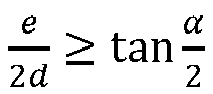
- Behälterbehandlungsmaschine nach einem der Ansprüche 9 bis 13, wobei die Transporteinrichtung eine Drehvorrichtung umfasst, die ausgebildet ist, einen von der Transporteinrichtung transportierten Behälter während der Beaufschlagung durch die Flammenpyrolyse-Einrichtungen so zu drehen, dass der Abstand der mit der Flamme beaufschlagten Oberfläche zu den Flammenpyrolyse-Einrichtungen stets gleich ist.
Applications Claiming Priority (1)
| Application Number | Priority Date | Filing Date | Title |
|---|---|---|---|
| DE102018212623.2A DE102018212623A1 (de) | 2018-07-27 | 2018-07-27 | Verfahren zum Aufbringen einer Funktions-Schicht auf einen Behälter |
Publications (2)
| Publication Number | Publication Date |
|---|---|
| EP3599092A1 EP3599092A1 (de) | 2020-01-29 |
| EP3599092B1 true EP3599092B1 (de) | 2024-07-24 |
Family
ID=67060298
Family Applications (1)
| Application Number | Title | Priority Date | Filing Date |
|---|---|---|---|
| EP19182132.1A Active EP3599092B1 (de) | 2018-07-27 | 2019-06-25 | Verfahren zum aufbringen einer funktions-schicht auf einen behälter |
Country Status (3)
| Country | Link |
|---|---|
| EP (1) | EP3599092B1 (de) |
| CN (1) | CN211222617U (de) |
| DE (1) | DE102018212623A1 (de) |
Families Citing this family (4)
| Publication number | Priority date | Publication date | Assignee | Title |
|---|---|---|---|---|
| DE102019128739A1 (de) * | 2019-10-24 | 2021-04-29 | Krones Ag | Behälterbehandlungsanlage und Verfahren zum Behandeln von Behältern |
| DE102023129442A1 (de) | 2023-10-25 | 2025-04-30 | Dekron Gmbh | Verfahren und Vorrichtung zum Vorbehandeln einer Oberfläche von Behältern vor einem Bedrucken |
| DE102023129445A1 (de) | 2023-10-25 | 2025-04-30 | Dekron Gmbh | Verfahren und Vorrichtung zum Vorbehandeln einer Oberfläche von Behältern vor einem Bedrucken |
| CN117774509B (zh) * | 2023-12-21 | 2025-12-26 | 华中科技大学 | 一种基于实时等离子体处理的绝缘表面电喷印装置及方法 |
Family Cites Families (14)
| Publication number | Priority date | Publication date | Assignee | Title |
|---|---|---|---|---|
| DE10019926A1 (de) * | 2000-04-20 | 2001-10-31 | Isimat Gmbh Siebdruckmaschinen | Verfahren zum Modifizieren einer Oberfläche eines kompakten Substrates |
| US7625059B2 (en) * | 2006-11-22 | 2009-12-01 | Plastipak Packaging, Inc. | Digital printing plastic containers |
| DE102010034780A1 (de) * | 2010-08-18 | 2012-02-23 | Volker Till | Vorrichtung und Verfahren zum Bedrucken von Behältern |
| DE102010044243A1 (de) * | 2010-09-02 | 2012-03-08 | Khs Gmbh | Verfahren zum digitalen Bedrucken von Behältern sowie Behälter mit wenigstens einem Aufdruck oder Druckbild |
| DE102011009393A1 (de) * | 2011-01-25 | 2012-07-26 | Krones Aktiengesellschaft | Vorrichtung und Verfahren zum Bedrucken von Behältern |
| DE102013208061A1 (de) * | 2013-01-31 | 2013-07-04 | Krones Ag | Vorrichtungen zum Bedrucken von Behältern und Verfahren dazu |
| DE102013207809A1 (de) * | 2013-04-29 | 2014-10-30 | Heidelberger Druckmaschinen Ag | Direktdruckverfahren mit Unterschicht |
| DE102013215637A1 (de) * | 2013-08-08 | 2015-03-05 | Krones Ag | Flexible Bedruckung von Behältern |
| DE102013110125A1 (de) * | 2013-09-13 | 2015-03-19 | Till Gmbh | Verfahren und Vorrichtung zur Oberflächenvorbehandlung eines dreidimensionalen Körpers |
| DE102015219975A1 (de) * | 2015-10-14 | 2017-04-20 | Krones Ag | Verfahren zum individuellen Bedrucken von Behältern |
| DE102016203722A1 (de) * | 2016-03-08 | 2017-09-14 | Krones Ag | Vorrichtung zum Bedrucken von Verschlüssen verschlossener Behälter |
| CA3023806A1 (en) * | 2016-05-12 | 2017-11-16 | Anheuser-Busch Inbev S.A. | A glass container having an inkjet printed image and a method for the manufacturing thereof |
| JP6754244B2 (ja) * | 2016-08-12 | 2020-09-09 | 東洋ガラス株式会社 | 表面処理をした樹脂コートガラス瓶、その製造方法、及び表面処理装置 |
| US10016997B1 (en) * | 2017-04-24 | 2018-07-10 | Xerox Corporation | Printer for providing multiple surface treatments to three-dimensional objects prior to printing and method for operating the printer |
-
2018
- 2018-07-27 DE DE102018212623.2A patent/DE102018212623A1/de not_active Withdrawn
-
2019
- 2019-06-25 EP EP19182132.1A patent/EP3599092B1/de active Active
- 2019-07-26 CN CN201921201806.1U patent/CN211222617U/zh active Active
Also Published As
| Publication number | Publication date |
|---|---|
| DE102018212623A1 (de) | 2020-01-30 |
| EP3599092A1 (de) | 2020-01-29 |
| CN211222617U (zh) | 2020-08-11 |
Similar Documents
| Publication | Publication Date | Title |
|---|---|---|
| EP3599092B1 (de) | Verfahren zum aufbringen einer funktions-schicht auf einen behälter | |
| EP3681724B1 (de) | Direktdruckmaschine zum aufbringen einer druckschicht auf behälter | |
| DE69509597T3 (de) | Hohler behälter mit inerter oder undurchlässiger innerer oberfläche durch plasmaunterstütze oberflächereaktion oder in situ polymerisation | |
| EP1388593B1 (de) | Schnelles Verfahren zur Herstellung von Mehrfachlagen-Barriereschichten | |
| EP3696875B1 (de) | Verfahren zur aufbringung einer isolationsschicht auf einer kfz-batteriezelle und beschichtungsstation sowie beschichtungsanlage zur durchführung des verfahrens | |
| EP0919015B1 (de) | Verfahren und vorrichtung zum auftragen von fotoresistlack auf nicht ebene grundkörperoberflächen | |
| DE2716183A1 (de) | Verfahren und vorrichtung zur ausbildung einer beschichtung aus einem metall oder einer metallverbindung auf einer flaeche | |
| EP3426495B1 (de) | Vorrichtung zum bedrucken von verschlüssen verschlossener behälter | |
| CH697933B1 (de) | Verfahren und Vorrichtung zur Beschichtung von Kunststofffolien mit einer Oxidschicht. | |
| EP2799243B1 (de) | Direktdruckverfahren zum Bedrucken von Behältern mit Deckschicht | |
| EP4137327A1 (de) | Bedruckungsverfahren für einen metallbehälter und vorrichtung zum bedrucken eines metallbehälters | |
| EP0701487A1 (de) | Vorrichtung zur belackung oder beschichtung von platten oder scheiben | |
| DE202019005563U1 (de) | Beschichtungsstation sowie Beschichtungsanlage zur Durchführung eines Verfahrens zur Aufbringung einer Isolationsschicht auf einer Kfz-Batteriezelle | |
| DE102016013317A1 (de) | Verfahren zum Herstellen eines dreidimensionalen Formgegenstands und Vorrichtung zur Durchführung des Verfahrens | |
| EP4360840B1 (de) | Verfahren zum erzeugen eines reliefartigen dekors auf einer oberfläche eines keramischen druckmediums | |
| DE102017101719B4 (de) | Druckmaschine mit selektiver vorbehandlung sowie verfahren zum bedrucken von werkstücken | |
| DE69017832T2 (de) | Verfahren und Vorrichtung für das Beschichten von Behältern mit kontrolliertem Profil. | |
| DE102008034743A1 (de) | Vorrichtung zum Bedrucken von Behältern | |
| DE69217384T2 (de) | Verbesserungen in bezug auf ein verfahren und eine vorrichtung zur beschichtung von gegenständen | |
| DE102023116243B4 (de) | Vorrichtung zum Auftragen einer Banderolierflüssigkeit auf Kapseln | |
| DE102023129356B4 (de) | Maschine zum Herstellen von aus Blechteilen gebildeten Dreiteildosen | |
| WO2020161278A1 (de) | Oberflächenbehandlung eines druckmediums mit radikalen | |
| EP3812161B1 (de) | Verfahren und vorrichtung zum beschichten eines substrats, zuschnitt und verpackung | |
| WO2021151655A1 (de) | Vorrichtung und verfahren zur beschichtung von kanälen einer probe mittels abscheidung aus der gasphase | |
| EP4335766A1 (de) | Vorrichtung und verfahren zum etikettieren eines behälters |
Legal Events
| Date | Code | Title | Description |
|---|---|---|---|
| PUAI | Public reference made under article 153(3) epc to a published international application that has entered the european phase |
Free format text: ORIGINAL CODE: 0009012 |
|
| STAA | Information on the status of an ep patent application or granted ep patent |
Free format text: STATUS: THE APPLICATION HAS BEEN PUBLISHED |
|
| AK | Designated contracting states |
Kind code of ref document: A1 Designated state(s): AL AT BE BG CH CY CZ DE DK EE ES FI FR GB GR HR HU IE IS IT LI LT LU LV MC MK MT NL NO PL PT RO RS SE SI SK SM TR |
|
| AX | Request for extension of the european patent |
Extension state: BA ME |
|
| STAA | Information on the status of an ep patent application or granted ep patent |
Free format text: STATUS: REQUEST FOR EXAMINATION WAS MADE |
|
| 17P | Request for examination filed |
Effective date: 20200716 |
|
| RBV | Designated contracting states (corrected) |
Designated state(s): AL AT BE BG CH CY CZ DE DK EE ES FI FR GB GR HR HU IE IS IT LI LT LU LV MC MK MT NL NO PL PT RO RS SE SI SK SM TR |
|
| STAA | Information on the status of an ep patent application or granted ep patent |
Free format text: STATUS: EXAMINATION IS IN PROGRESS |
|
| 17Q | First examination report despatched |
Effective date: 20230519 |
|
| P01 | Opt-out of the competence of the unified patent court (upc) registered |
Effective date: 20230523 |
|
| GRAP | Despatch of communication of intention to grant a patent |
Free format text: ORIGINAL CODE: EPIDOSNIGR1 |
|
| STAA | Information on the status of an ep patent application or granted ep patent |
Free format text: STATUS: GRANT OF PATENT IS INTENDED |
|
| INTG | Intention to grant announced |
Effective date: 20240222 |
|
| GRAS | Grant fee paid |
Free format text: ORIGINAL CODE: EPIDOSNIGR3 |
|
| GRAA | (expected) grant |
Free format text: ORIGINAL CODE: 0009210 |
|
| STAA | Information on the status of an ep patent application or granted ep patent |
Free format text: STATUS: THE PATENT HAS BEEN GRANTED |
|
| AK | Designated contracting states |
Kind code of ref document: B1 Designated state(s): AL AT BE BG CH CY CZ DE DK EE ES FI FR GB GR HR HU IE IS IT LI LT LU LV MC MK MT NL NO PL PT RO RS SE SI SK SM TR |
|
| REG | Reference to a national code |
Ref country code: GB Ref legal event code: FG4D Free format text: NOT ENGLISH |
|
| REG | Reference to a national code |
Ref country code: CH Ref legal event code: EP |
|
| REG | Reference to a national code |
Ref country code: DE Ref legal event code: R096 Ref document number: 502019011723 Country of ref document: DE |
|
| REG | Reference to a national code |
Ref country code: IE Ref legal event code: FG4D Free format text: LANGUAGE OF EP DOCUMENT: GERMAN |
|
| REG | Reference to a national code |
Ref country code: LT Ref legal event code: MG9D |
|
| REG | Reference to a national code |
Ref country code: NL Ref legal event code: MP Effective date: 20240724 |
|
| PG25 | Lapsed in a contracting state [announced via postgrant information from national office to epo] |
Ref country code: PT Free format text: LAPSE BECAUSE OF FAILURE TO SUBMIT A TRANSLATION OF THE DESCRIPTION OR TO PAY THE FEE WITHIN THE PRESCRIBED TIME-LIMIT Effective date: 20241125 |
|
| PG25 | Lapsed in a contracting state [announced via postgrant information from national office to epo] |
Ref country code: NL Free format text: LAPSE BECAUSE OF FAILURE TO SUBMIT A TRANSLATION OF THE DESCRIPTION OR TO PAY THE FEE WITHIN THE PRESCRIBED TIME-LIMIT Effective date: 20240724 |
|
| PG25 | Lapsed in a contracting state [announced via postgrant information from national office to epo] |
Ref country code: PT Free format text: LAPSE BECAUSE OF FAILURE TO SUBMIT A TRANSLATION OF THE DESCRIPTION OR TO PAY THE FEE WITHIN THE PRESCRIBED TIME-LIMIT Effective date: 20241125 Ref country code: NL Free format text: LAPSE BECAUSE OF FAILURE TO SUBMIT A TRANSLATION OF THE DESCRIPTION OR TO PAY THE FEE WITHIN THE PRESCRIBED TIME-LIMIT Effective date: 20240724 |
|
| PG25 | Lapsed in a contracting state [announced via postgrant information from national office to epo] |
Ref country code: NO Free format text: LAPSE BECAUSE OF FAILURE TO SUBMIT A TRANSLATION OF THE DESCRIPTION OR TO PAY THE FEE WITHIN THE PRESCRIBED TIME-LIMIT Effective date: 20241024 |
|
| PG25 | Lapsed in a contracting state [announced via postgrant information from national office to epo] |
Ref country code: FI Free format text: LAPSE BECAUSE OF FAILURE TO SUBMIT A TRANSLATION OF THE DESCRIPTION OR TO PAY THE FEE WITHIN THE PRESCRIBED TIME-LIMIT Effective date: 20240724 Ref country code: PL Free format text: LAPSE BECAUSE OF FAILURE TO SUBMIT A TRANSLATION OF THE DESCRIPTION OR TO PAY THE FEE WITHIN THE PRESCRIBED TIME-LIMIT Effective date: 20240724 Ref country code: GR Free format text: LAPSE BECAUSE OF FAILURE TO SUBMIT A TRANSLATION OF THE DESCRIPTION OR TO PAY THE FEE WITHIN THE PRESCRIBED TIME-LIMIT Effective date: 20241025 |
|
| PG25 | Lapsed in a contracting state [announced via postgrant information from national office to epo] |
Ref country code: BG Free format text: LAPSE BECAUSE OF FAILURE TO SUBMIT A TRANSLATION OF THE DESCRIPTION OR TO PAY THE FEE WITHIN THE PRESCRIBED TIME-LIMIT Effective date: 20240724 |
|
| PG25 | Lapsed in a contracting state [announced via postgrant information from national office to epo] |
Ref country code: LV Free format text: LAPSE BECAUSE OF FAILURE TO SUBMIT A TRANSLATION OF THE DESCRIPTION OR TO PAY THE FEE WITHIN THE PRESCRIBED TIME-LIMIT Effective date: 20240724 |
|
| PG25 | Lapsed in a contracting state [announced via postgrant information from national office to epo] |
Ref country code: IS Free format text: LAPSE BECAUSE OF FAILURE TO SUBMIT A TRANSLATION OF THE DESCRIPTION OR TO PAY THE FEE WITHIN THE PRESCRIBED TIME-LIMIT Effective date: 20241124 |
|
| PG25 | Lapsed in a contracting state [announced via postgrant information from national office to epo] |
Ref country code: HR Free format text: LAPSE BECAUSE OF FAILURE TO SUBMIT A TRANSLATION OF THE DESCRIPTION OR TO PAY THE FEE WITHIN THE PRESCRIBED TIME-LIMIT Effective date: 20240724 |
|
| PG25 | Lapsed in a contracting state [announced via postgrant information from national office to epo] |
Ref country code: ES Free format text: LAPSE BECAUSE OF FAILURE TO SUBMIT A TRANSLATION OF THE DESCRIPTION OR TO PAY THE FEE WITHIN THE PRESCRIBED TIME-LIMIT Effective date: 20240724 Ref country code: RS Free format text: LAPSE BECAUSE OF FAILURE TO SUBMIT A TRANSLATION OF THE DESCRIPTION OR TO PAY THE FEE WITHIN THE PRESCRIBED TIME-LIMIT Effective date: 20241024 |
|
| PG25 | Lapsed in a contracting state [announced via postgrant information from national office to epo] |
Ref country code: RS Free format text: LAPSE BECAUSE OF FAILURE TO SUBMIT A TRANSLATION OF THE DESCRIPTION OR TO PAY THE FEE WITHIN THE PRESCRIBED TIME-LIMIT Effective date: 20241024 Ref country code: PL Free format text: LAPSE BECAUSE OF FAILURE TO SUBMIT A TRANSLATION OF THE DESCRIPTION OR TO PAY THE FEE WITHIN THE PRESCRIBED TIME-LIMIT Effective date: 20240724 Ref country code: NO Free format text: LAPSE BECAUSE OF FAILURE TO SUBMIT A TRANSLATION OF THE DESCRIPTION OR TO PAY THE FEE WITHIN THE PRESCRIBED TIME-LIMIT Effective date: 20241024 Ref country code: LV Free format text: LAPSE BECAUSE OF FAILURE TO SUBMIT A TRANSLATION OF THE DESCRIPTION OR TO PAY THE FEE WITHIN THE PRESCRIBED TIME-LIMIT Effective date: 20240724 Ref country code: IS Free format text: LAPSE BECAUSE OF FAILURE TO SUBMIT A TRANSLATION OF THE DESCRIPTION OR TO PAY THE FEE WITHIN THE PRESCRIBED TIME-LIMIT Effective date: 20241124 Ref country code: HR Free format text: LAPSE BECAUSE OF FAILURE TO SUBMIT A TRANSLATION OF THE DESCRIPTION OR TO PAY THE FEE WITHIN THE PRESCRIBED TIME-LIMIT Effective date: 20240724 Ref country code: GR Free format text: LAPSE BECAUSE OF FAILURE TO SUBMIT A TRANSLATION OF THE DESCRIPTION OR TO PAY THE FEE WITHIN THE PRESCRIBED TIME-LIMIT Effective date: 20241025 Ref country code: FI Free format text: LAPSE BECAUSE OF FAILURE TO SUBMIT A TRANSLATION OF THE DESCRIPTION OR TO PAY THE FEE WITHIN THE PRESCRIBED TIME-LIMIT Effective date: 20240724 Ref country code: ES Free format text: LAPSE BECAUSE OF FAILURE TO SUBMIT A TRANSLATION OF THE DESCRIPTION OR TO PAY THE FEE WITHIN THE PRESCRIBED TIME-LIMIT Effective date: 20240724 Ref country code: BG Free format text: LAPSE BECAUSE OF FAILURE TO SUBMIT A TRANSLATION OF THE DESCRIPTION OR TO PAY THE FEE WITHIN THE PRESCRIBED TIME-LIMIT Effective date: 20240724 |
|
| PG25 | Lapsed in a contracting state [announced via postgrant information from national office to epo] |
Ref country code: DK Free format text: LAPSE BECAUSE OF FAILURE TO SUBMIT A TRANSLATION OF THE DESCRIPTION OR TO PAY THE FEE WITHIN THE PRESCRIBED TIME-LIMIT Effective date: 20240724 Ref country code: SM Free format text: LAPSE BECAUSE OF FAILURE TO SUBMIT A TRANSLATION OF THE DESCRIPTION OR TO PAY THE FEE WITHIN THE PRESCRIBED TIME-LIMIT Effective date: 20240724 Ref country code: RO Free format text: LAPSE BECAUSE OF FAILURE TO SUBMIT A TRANSLATION OF THE DESCRIPTION OR TO PAY THE FEE WITHIN THE PRESCRIBED TIME-LIMIT Effective date: 20240724 |
|
| PG25 | Lapsed in a contracting state [announced via postgrant information from national office to epo] |
Ref country code: EE Free format text: LAPSE BECAUSE OF FAILURE TO SUBMIT A TRANSLATION OF THE DESCRIPTION OR TO PAY THE FEE WITHIN THE PRESCRIBED TIME-LIMIT Effective date: 20240724 |
|
| PG25 | Lapsed in a contracting state [announced via postgrant information from national office to epo] |
Ref country code: CZ Free format text: LAPSE BECAUSE OF FAILURE TO SUBMIT A TRANSLATION OF THE DESCRIPTION OR TO PAY THE FEE WITHIN THE PRESCRIBED TIME-LIMIT Effective date: 20240724 |
|
| REG | Reference to a national code |
Ref country code: DE Ref legal event code: R097 Ref document number: 502019011723 Country of ref document: DE |
|
| PG25 | Lapsed in a contracting state [announced via postgrant information from national office to epo] |
Ref country code: IT Free format text: LAPSE BECAUSE OF FAILURE TO SUBMIT A TRANSLATION OF THE DESCRIPTION OR TO PAY THE FEE WITHIN THE PRESCRIBED TIME-LIMIT Effective date: 20240724 Ref country code: SK Free format text: LAPSE BECAUSE OF FAILURE TO SUBMIT A TRANSLATION OF THE DESCRIPTION OR TO PAY THE FEE WITHIN THE PRESCRIBED TIME-LIMIT Effective date: 20240724 |
|
| PLBE | No opposition filed within time limit |
Free format text: ORIGINAL CODE: 0009261 |
|
| STAA | Information on the status of an ep patent application or granted ep patent |
Free format text: STATUS: NO OPPOSITION FILED WITHIN TIME LIMIT |
|
| 26N | No opposition filed |
Effective date: 20250425 |
|
| PGFP | Annual fee paid to national office [announced via postgrant information from national office to epo] |
Ref country code: DE Payment date: 20250429 Year of fee payment: 7 |
|
| PG25 | Lapsed in a contracting state [announced via postgrant information from national office to epo] |
Ref country code: SE Free format text: LAPSE BECAUSE OF FAILURE TO SUBMIT A TRANSLATION OF THE DESCRIPTION OR TO PAY THE FEE WITHIN THE PRESCRIBED TIME-LIMIT Effective date: 20240724 |
|
| REG | Reference to a national code |
Ref country code: CH Ref legal event code: H13 Free format text: ST27 STATUS EVENT CODE: U-0-0-H10-H13 (AS PROVIDED BY THE NATIONAL OFFICE) Effective date: 20260127 |
|
| PG25 | Lapsed in a contracting state [announced via postgrant information from national office to epo] |
Ref country code: MC Free format text: LAPSE BECAUSE OF FAILURE TO SUBMIT A TRANSLATION OF THE DESCRIPTION OR TO PAY THE FEE WITHIN THE PRESCRIBED TIME-LIMIT Effective date: 20240724 |
|
| PG25 | Lapsed in a contracting state [announced via postgrant information from national office to epo] |
Ref country code: LU Free format text: LAPSE BECAUSE OF NON-PAYMENT OF DUE FEES Effective date: 20250625 |
|
| GBPC | Gb: european patent ceased through non-payment of renewal fee |
Effective date: 20250625 |
|
| REG | Reference to a national code |
Ref country code: BE Ref legal event code: MM Effective date: 20250630 |
|
| PG25 | Lapsed in a contracting state [announced via postgrant information from national office to epo] |
Ref country code: GB Free format text: LAPSE BECAUSE OF NON-PAYMENT OF DUE FEES Effective date: 20250625 |
|
| PG25 | Lapsed in a contracting state [announced via postgrant information from national office to epo] |
Ref country code: IE Free format text: LAPSE BECAUSE OF NON-PAYMENT OF DUE FEES Effective date: 20250625 |
|
| PG25 | Lapsed in a contracting state [announced via postgrant information from national office to epo] |
Ref country code: BE Free format text: LAPSE BECAUSE OF NON-PAYMENT OF DUE FEES Effective date: 20250630 |
|
| PG25 | Lapsed in a contracting state [announced via postgrant information from national office to epo] |
Ref country code: FR Free format text: LAPSE BECAUSE OF NON-PAYMENT OF DUE FEES Effective date: 20250630 |
|
| PG25 | Lapsed in a contracting state [announced via postgrant information from national office to epo] |
Ref country code: CH Free format text: LAPSE BECAUSE OF NON-PAYMENT OF DUE FEES Effective date: 20250630 |