EP3599368A1 - Abgasdüsenbaugruppe - Google Patents
Abgasdüsenbaugruppe Download PDFInfo
- Publication number
- EP3599368A1 EP3599368A1 EP19181190.0A EP19181190A EP3599368A1 EP 3599368 A1 EP3599368 A1 EP 3599368A1 EP 19181190 A EP19181190 A EP 19181190A EP 3599368 A1 EP3599368 A1 EP 3599368A1
- Authority
- EP
- European Patent Office
- Prior art keywords
- exhaust
- cowl
- centre
- mixer
- axially
- Prior art date
- Legal status (The legal status is an assumption and is not a legal conclusion. Google has not performed a legal analysis and makes no representation as to the accuracy of the status listed.)
- Granted
Links
Images



Classifications
-
- F—MECHANICAL ENGINEERING; LIGHTING; HEATING; WEAPONS; BLASTING
- F02—COMBUSTION ENGINES; HOT-GAS OR COMBUSTION-PRODUCT ENGINE PLANTS
- F02K—JET-PROPULSION PLANTS
- F02K1/00—Plants characterised by the form or arrangement of the jet pipe or nozzle; Jet pipes or nozzles peculiar thereto
- F02K1/46—Nozzles having means for adding air to the jet or for augmenting the mixing region between the jet and the ambient air, e.g. for silencing
-
- F—MECHANICAL ENGINEERING; LIGHTING; HEATING; WEAPONS; BLASTING
- F02—COMBUSTION ENGINES; HOT-GAS OR COMBUSTION-PRODUCT ENGINE PLANTS
- F02K—JET-PROPULSION PLANTS
- F02K1/00—Plants characterised by the form or arrangement of the jet pipe or nozzle; Jet pipes or nozzles peculiar thereto
- F02K1/06—Varying effective area of jet pipe or nozzle
- F02K1/09—Varying effective area of jet pipe or nozzle by axially moving an external member, e.g. a shroud
-
- F—MECHANICAL ENGINEERING; LIGHTING; HEATING; WEAPONS; BLASTING
- F02—COMBUSTION ENGINES; HOT-GAS OR COMBUSTION-PRODUCT ENGINE PLANTS
- F02K—JET-PROPULSION PLANTS
- F02K1/00—Plants characterised by the form or arrangement of the jet pipe or nozzle; Jet pipes or nozzles peculiar thereto
- F02K1/06—Varying effective area of jet pipe or nozzle
-
- F—MECHANICAL ENGINEERING; LIGHTING; HEATING; WEAPONS; BLASTING
- F02—COMBUSTION ENGINES; HOT-GAS OR COMBUSTION-PRODUCT ENGINE PLANTS
- F02K—JET-PROPULSION PLANTS
- F02K1/00—Plants characterised by the form or arrangement of the jet pipe or nozzle; Jet pipes or nozzles peculiar thereto
- F02K1/38—Introducing air inside the jet
- F02K1/386—Introducing air inside the jet mixing devices in the jet pipe, e.g. for mixing primary and secondary flow
Definitions
- the present invention relates to a variable exhaust area nozzle assembly for a gas turbine engine such as a gas turbine engine for use on a supersonic aircraft.
- a gas turbine typically comprises, in axial flow series, an air intake, a propulsive fan, an intermediate pressure compressor, a high-pressure compressor, combustion equipment, a high-pressure turbine, an intermediate pressure turbine, a low-pressure turbine and an exhaust nozzle.
- a nacelle generally surrounds the engine and defines both the intake and the exhaust nozzle.
- Air entering the intake is accelerated by the fan to produce two air flows: a core flow into the intermediate pressure compressor and a bypass flow which passes through a bypass passage to provide propulsive thrust.
- the intermediate pressure compressor compresses the air flow directed into it before delivering that air to the high pressure compressor where further compression takes place.
- the compressed air exhausted from the high-pressure compressor is directed into the combustion equipment where it is mixed with fuel and the mixture combusted.
- the resultant hot combustion products then expand through, and thereby drive the high, intermediate and low-pressure turbines before being exhausted through the nozzle to provide propulsive thrust.
- Mixed turbofans combine the (hot) core and (cooler) bypass flows upstream of the nozzle to gain thrust from the combining of two streams of different temperatures.
- a mixer nozzle is typically provided with an outlet at the mixing plane.
- the mixer nozzle may comprise a series of lobes, chutes or serrations to promote mixing between the core flow and bypass flow.
- Varying the area ratio of the core and bypass flows at the mixing plane and varying the area of the final exhaust nozzle produces a number of potential advantages to the engine's thermodynamic cycle in terms of performance and acoustics.
- the engine is able to operate at maximum flow capacity which reduces the specific thrust and jet velocity and thus reduces engine noise (which is strongly linked to jet velocity).
- fuel efficiency under cruise conditions is maximised by reducing the final exhaust nozzle area and reducing the core flow area to increase the specific thrust and jet velocity.
- the present disclosure aims to provide an exhaust nozzle assembly capable of varying the core exit area and final exhaust exit area without adding significant weight, complexity and cost to the engine manufacture and operation.
- the present disclosure provides an exhaust nozzle assembly for a gas turbine engine having a centre axis, and a gas turbine engine, as set out in the appended claims.
- an exhaust nozzle assembly for a gas turbine engine having a centre axis comprising:
- the core exit area and exhaust exit area are adjustable in unison between a first (maximum area) position which is optimised for take-off and a second (minimum area) position which is optimised for cruise conditions.
- the single actuation mechanism reduces engine complexity, weight and thus cost compared to known systems with separate actuation of the mixer and exhaust nozzles.
- actuation to effect translation/adjustment of the cowls allows positioning of the actuation mechanism outside of the hot engine core meaning that the temperatures to which the actuation mechanism is exposed are reduced. Positioning of the actuators outside of the engine core also allows easier access to the actuation mechanism e.g. for plumbing purposes and for maintenance.
- the mixer cowl comprises a mounting portion and convergent portion converging from the mounting portion.
- the downstream extremity of the mixer cowl defines the outer periphery of the core exit area (at the mixing plane).
- the mounting portion is a parallel (cylindrical) portion which is slidably mounted on a static engine core structure within the mixer nozzle.
- the mixer nozzle is a lobed mixer nozzle or a forced chuted mixer nozzle and the axially-translatable mixer cowl (e.g. the convergent portion of the mixer cowl) comprises lobes/chutes to assist in intermixing between the core (hot) flow and the bypass (cooler) flow at the mixing plane.
- the mixer cowl e.g. the convergent portion of the mixer cowl
- the exhaust cowl may comprise a mounting portion and convergent portion converging from the mounting portion.
- the downstream extremity of the exhaust cowl defines the outer periphery of the exhaust exit area.
- the mounting portion is a parallel (cylindrical) portion which is slidably mounted on the nacelle surrounding the engine.
- the centre-body comprises an axial variation in its diameter/radial cross-section i.e. the diameter/radial cross-section varies from its upstream end to its downstream end.
- upstream is used to indicate a direction towards the fan and the term “downstream” is used to indicate a direction towards the exhaust nozzle.
- the centre-body comprises, in an axial downstream direction, a waist portion and a head portion, the waist portion having a smaller diameter than the head portion.
- the waist portion may be a parallel (cylindrical) portion.
- the head portion comprises in an axial downstream direction, a diverging portion (diverging from the waist portion) and a converging end portion (which may be a conical end portion). The plane of deflection between the diverging and converging head portions will be the maximum diameter portion of the head portion.
- the waist portion may be mounted to a static engine core structure.
- the centre-body may further comprise an axially upstream convergent portion which may converge to the waist portion from an axially upstream mounting portion which may be a parallel portion.
- the mounting portion is mounted to a static engine core structure.
- the centre-body extends downstream from the mixer nozzle through the exhaust nozzle.
- the exhaust duct is defined by the exit nozzle and the centre-body.
- the centre-body extends downstream from the mixer nozzle by terminates with its converging downstream end within the exhaust duct upstream of the exhaust exit area.
- the first position of the axially-translatable mixer and exhaust cowls is a downstream position with the cowls extended in a downstream direction (away from the engine fan).
- the second position of the axially-translatable mixer and exhaust cowls is an upstream position with the cowls retracted in an upstream direction (towards the engine fan).
- the core exit area i.e. the mixing plane
- the core exit area may be axially aligned with the centre-body at a portion having a diameter less than the maximum diameter of the head portion of the centre-body.
- the core exit area may be aligned with the waist portion of the centre-body or may be aligned proximal to the waist portion e.g. with the converging portion upstream of the waist portion.
- the exhaust exit area may be axially aligned with the head portion of the centre-body at a portion having a diameter less than the maximum diameter of the head portion e.g.
- the core exit and exhaust exit areas are maximised since the radial surface area of the centre-body in each area is reduced/minimised.
- the core exit area in the second (upstream) position, may be axially aligned with the centre-body at a portion having a diameter greater than the minimum diameter of the centre-body e.g. it may be aligned with the mounting portion of the centre-body or may be aligned with the converging portion downstream of (e.g. proximal to) the mounting portion.
- the exhaust exit area in the second position, may be axially aligned with the head portion at a position having a greater diameter than in the first position e.g. it may be axially aligned with or proximal to the deflection between the diverging and converging head portion where the head portion has the maximum diameter. In this way, the core exit and exhaust exit areas are minimised since the diameter/radial surface area of the centre-body in each area is increased/maximised.
- the first position of the axially-translatable mixer cowl is a downstream position with the cowl extended in a downstream direction (away from the engine fan).
- the second position of the axially-translatable mixer cowl is an upstream position with the cowl retracted in an upstream direction (towards the engine fan).
- the axial position of the exhaust cowl is fixed relative to the centre-body but the angle the cowl makes relative to the centre axis is adjustable.
- the core exit area in the first (downstream) position, may be axially aligned with the centre-body at a portion having a diameter less than the maximum diameter of the /head portion centre-body, e.g. it may be aligned at the converging portion of the head portion of the centre-body proximal the downstream extremity of the centre-body. In this way, the core exit area is maximised since the radial surface area of the centre-body is reduced/minimised.
- the core exit area in the second (upstream) position, may be axially aligned with the centre-body at a portion having a greater diameter than the minimum dimeter of the centre-body/head portion e.g. it may be aligned with the converging portion of the head portion of the centre-body at or proximal to the deflection between the diverging and converging head portion where the head portion has the maximum diameter. In this way, the core exit area is minimised since the diameter/radial surface area of the centre-body is increased/maximised.
- the exhaust cowl In the first position, the exhaust cowl is angularly adjusted to increase the exhaust exit area and in the second position the exhaust cowl is angularly adjusted to decrease the exhaust exit area.
- the exhaust cowl may comprise a series of circumferentially-arranged cowl petals, each cowl petal having a fixed upstream end and a free downstream end wherein the free ends can pivot/hinge about their respective fixed ends to adjust the angle each cowl petal makes relative to the engine axis.
- the free-ends In the first position, the free-ends move away from the centre axis, such that the angle between each cowl petal and the centre axis decreases and the exhaust exit area increases.
- the free-ends are pivoted towards the centre axis, such that the angle between each cowl petal and the centre axis increases and the exhaust exit area decreases.
- the actuator mechanism acts to move/adjust both the mixer and exhaust cowls in unison between the first and second positions. It may be provided externally to the engine core thus reducing the temperatures to which the actuator is exposed and allowing easier access for plumbing and maintenance.
- the actuator mechanism may comprise at least one actuator mounted within and to the static engine core structure. There may be a plurality of circumferentially arranged actuators.
- the or each actuator may comprise a linear actuator e.g. a piston.
- the or each actuator may be a hydraulic, pneumatic or electronic actuator.
- the actuator mechanism e.g. the or each actuator/piston may comprise at least one axial linkage/shaft extending between and operatively coupling the mixer cowl and exhaust cowl such that axial translation of the axial linkage/shaft by the actuator(s) results in axial translation of the mixer cowl and either axial translation or angular adjustment of the exhaust cowl.
- the actuation mechanism may comprise a radial linkage extending from the or each axial linkage/shaft to the mixer cowl in order to transfer the axial motion of the axial linkage/shaft to the mixer cowl.
- the actuation mechanism may further comprise a downstream radial linkage extending from the or each axial linkage/shaft to the exhaust cowl in order to transfer the axial motion of the axial linkage/shaft to the exhaust cowl.
- the actuation mechanism may comprise one or more rollers each seated on a respective radially outer cam surface of the exhaust cowl.
- the or each roller may be connected directly or indirectly to a respective one of the axial linkages/shafts.
- a plurality of rollers may be coupled to a unison ring surrounding the radially outer surface of the exhaust cowl, the unison ring being connected to one or more axial linkages.
- each roller associated with one of the cowl petals may have a cam surface on its radially outer surface so that when a roller is in an upstream (second) position on the respective cam surface, the free end of the cowl petal is forced towards the centre axis of the engine thus reducing the exhaust exit area.
- Actuation of the actuation mechanism causes the roller(s) to move over/down the cam surface to a downstream (first) position to allow the free end of the associated cowl petal to move away from the engine centre axis thus increasing the area of the exhaust exit area.
- the unison ring ensure that all cowl petals associated with a roller move to the same extent at the same time i.e. move in unison. It also allows the number of actuators/pistons to be lower than the number of rollers.
- the nozzle assembly further comprises a divergent section downstream of the exhaust nozzle/exhaust exit area.
- This divergent section may have a fixed or variable geometry. Where the divergent section is of variable geometry, it may be operably coupled to the actuator mechanism or it may be actuated by a second, separate actuation mechanism.
- a gas turbine engine having an exhaust nozzle assembly according to the first aspect.
- a supersonic aircraft having a gas turbine engine according to the second aspect.
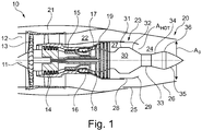
- a gas turbine engine is generally indicated at 10, having a principal and rotational axis 11, also known as a centre axis.
- the gas turbine engine 10 comprises, in axial flow series, an air intake 12, a propulsive fan 13, an intermediate pressure compressor 14, a high-pressure compressor 15, combustion equipment 16, a high-pressure turbine 17, an intermediate pressure turbine 18, a low-pressure turbine 19 and an exhaust nozzle 20.
- a nacelle 21 generally surrounds the engine 10 and defines both the intake 12 and the exhaust nozzle 20.
- the gas turbine engine 10 works in the conventional manner so that air entering the intake 12 is accelerated by the fan 13 to produce two air flows: a core flow into the intermediate pressure compressor 14 and a bypass flow which passes through a bypass duct 22 to provide propulsive thrust.
- the intermediate pressure compressor 14 compresses the air flow directed into it before delivering that air to the high pressure compressor 15 where further compression takes place.
- the compressed air exhausted from the high-pressure compressor 15 is directed into the combustion equipment 16 where it is mixed with fuel and the mixture combusted.
- the resultant hot combustion products then expand through, and thereby drive the high, intermediate and low-pressure turbines 17, 18, 19 before being exhausted through the nozzle 20 to provide additional propulsive thrust.
- the high 17, intermediate 18 and low 19 pressure turbines drive respectively the high pressure compressor 15, intermediate pressure compressor 14 and fan 13, each by suitable interconnecting shaft.
- the exhaust nozzle assembly shown in Figure 1 comprises a radially inner mixer nozzle 23 and the radially outer exhaust nozzle 20.
- the exhaust nozzle 20 extends axially downstream of the mixer nozzle 23.
- the exhaust nozzle 20 defines the radially outer periphery of an exhaust duct 24 and at its downstream axial end, defines the radially outer periphery of an exhaust exit area A 8 .
- the exhaust nozzle 20 comprises an annular mounting portion 25 and an axially-translatable converging exhaust cowl 26.
- the mounting portion 25 is slidably mounted on the nacelle 21
- the mixer nozzle 23 defines the radially outer periphery of a core flow duct 27 and at its downstream axial end, defines the radially outer periphery of a core exit area A HOT .
- the core exit area A HOT forms part of a mixing plane where hot core flow from the engine core and cooler bypass flow from the bypass duct 22 mix.
- the mixer nozzle 23 comprises an annular mounting portion 28 and an axially-translatable converging mixer cowl 29.
- the mounting portion 28 is slidably mounted on a static portion of the engine core.
- the mixer cowl 29 may comprise lobes or chutes (not shown) to facilitate mixing of the core flow and the bypass flow at the mixing plane.
- the assembly further comprises a centre-body 30 axially mounted within and extending axially downstream from the mixer nozzle 23.
- the centre-body 30 has an axial variation in its diameter/radial cross-section i.e. the diameter/radial cross-section varies from its upstream end to its downstream end.
- the centre-body comprises, in an axial downstream direction, an annular mounting portion 31 mounted to a static engine core structure, a converging portion 32 converging from the mounting portion 31 to an annular waist portion 33.
- the waist portion has the smallest diameter along the centre-body.
- the waist portion is connected to a downstream head portion comprising a diverging portion 34 (diverging from the waist portion) and a converging end portion 35 which is conical.
- the plane of deflection 36 between the diverging head portion 34 and converging end portion 35 is the maximum diameter portion of the head portion.
- the centre-body 30 defines the radially inner periphery of the (annular) core flow duct 27 and of the (annular) exhaust duct 24.
- the mixer cowl 29 and the exhaust cowl 26 are in a downstream position with the cowls 29, 26 extended away from the engine core.
- the core exit area A HOT (at the mixing plane) is axially aligned proximal the waist portion 33 i.e. at the converging portion 32 proximal the waist portion. At this position, the diameter of the core body 30 is approaching a minimum diameter.
- the exhaust exit area A 8 is axially aligned with the head portion of the centre-body at a portion having a diameter less than the maximum diameter of the head portion i.e. it is aligned with the converging (conical) end portion 35 of the head portion of the centre-body 30.
- the core exit area A 8 and exhaust exit area A HOT are maximised since the radial surface area/diameter of the centre-body 30 in each area is reduced/minimised. This decreases the jet velocity and specific thrust to optimise the engine for take-off conditions with reduced engine noise.
- the core exit area A HOT (at the mixing plane) is axially aligned with the annular mounting portion 31 where the diameter of the core body 30 has a maximum diameter.
- the exhaust exit area A 8 is axially aligned with the maximum diameter portion of the head portion of the centre-body 30 where the diverging portion 34 deflects to the converging end portion 35.
- the mixer cowl 29 and exhaust cowl 26 are both operatively linked to a single actuation mechanism (not shown) which preferably comprises a liner actuator e.g. a hydraulic piston which effects axial translation of an axial shaft having radial linkages to the mixer cowl 29 and exhaust cowl 26.
- a liner actuator e.g. a hydraulic piston which effects axial translation of an axial shaft having radial linkages to the mixer cowl 29 and exhaust cowl 26.
- the radial linkages transfer the axial translation of the axial linkages to the cowls 29, 26.
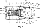
- Figures 3 and 4 show a second embodiment which is as described above for the first embodiment unless otherwise indicated.
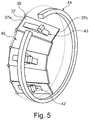
- the exhaust nozzle 20' in the second embodiment has an angularly-adjustable exhaust cowl 26' comprising a series of circumferentially-arranged cowl petals 37 as shown in Figure 5 , each cowl petal 37 having a fixed upstream end 37a and a free downstream end 37b.
- the fixed ends 37a are each connected to the nacelle 21 by a respective hinge 38 so that the free ends 37b can pivot towards and away from the centre axis 11 to adjust the angle each cowl petal 37 makes relative to the engine axis 11.
- the centre-body 30' is axially mounted within and extends axially downstream from the mounting portion 28' and mixer nozzle 23' towards the exhaust nozzle 20'. However, in the second embodiment, the downstream end of the centre-body 30' terminates prior to the exhaust exit area A 8 . Thus the centre-body 30' defines the inner periphery of the annular core flow duct 27' but does not impinge on the exhaust exit area A 8 .
- the centre-body 30' comprises, in an axial downstream direction, an annular waist portion 33' which is mounted to a static engine core structure.
- the waist portion 33' has the smallest diameter along the centre-body 30'.
- the waist portion is connected to a downstream head portion comprising a diverging portion 34' (diverging from the waist portion 33') and a converging end portion 35' which is conical.
- the plane of deflection between the diverging head portion 34' and converging end portion 35' is the maximum diameter portion of the head portion/centre-body 30'.
- the mixer cowl 29' is in a downstream position extended away from the engine core.
- the core exit area A HOT (at the mixing plane) is axially aligned with the converging end portion 35' of the head portion of the centre-body 30' proximal the downstream end of the centre-body. At this position, the diameter of the core body 30' is approaching a minimum diameter.
- the angle of the exhaust cowl 26' relative to the engine axis 11 is small (e.g. less than around 20 degrees) (i.e. the free ends 37b of the cowl petals 37 are remote from the centre axis 11 such that that they are almost parallel to the centre axis).
- the core exit area A 8 and exhaust exit area A HOT are maximised since the radial surface area/diameter of the centre-body 30' in the core exit area A HOT is reduced/minimised and the diameter of the exhaust cowl 26' is increased. This decreases the jet velocity and specific thrust to optimise the engine for take-off conditions with reduced engine noise.
- the mixer cowl 29' is in a downstream position extended away from the engine core.
- the core exit area A HOT (at the mixing plane) is axially aligned with the converging end portion 35' of the head portion of the centre-body 30' proximal the deflection 36'. At this position, the diameter of the core body 30' is greater than the diameter of the portion aligned with the core exit area A HOT in the first position.
- the angle of the exhaust cowl 26' relative to the engine axis 11 is increased (e.g. greater than around 30 degrees) (i.e. the free ends 37b of the cowl petals 37 move towards the centre axis 11).
- the core exit area A 8 and exhaust exit area A HOT are minimised since the radial surface area/diameter of the centre-body 30' in the core exit area A HOT is increased/maximised and the diameter of the exhaust cowl 26' is decreased. This increases the jet velocity and specific thrust to optimise the engine for cruise conditions.
- the mixer cowl 29' and exhaust cowl 26' are both operatively linked to a single actuation mechanism which comprises a plurality of circumferentially-arranged linear actuators 39 (e.g. hydraulic or pneumatic pistons or screw jacks) each connected to a respective axial shaft 39a having a radial linkage 40 to the mixer cowl 29.
- the radial linkages 40 transfer the axial translation of the axial shaft 39a to the cowls 29.
- the actuation mechanism also comprises a plurality of rollers 42 each seated on a respective radially outer cam surface 43 of an exhaust petal 37 as shown in Figure 5 .
- the rollers 42 are coupled to a unison ring 44 surrounding the radially outer surface of the cowl petals 37, the unison ring 44 being connected to the axial shafts 39a.
- Actuation of the hydraulic pistons causes the rollers 42 to move axially over/down the cam surface 43 to a downstream (first) position ( Figure 6b ) to allow the free end 37b of the associated cowl petal 37 to move away from the engine centre axis 11 thus increasing the area of the exhaust exit area A 8 .
- the unison ring 44 ensures that all cowl petals 37 associated with a roller 42 move to the same extent at the same time i.e. move in unison. As can be seen in Figure 5 , not all cowl petals 37 require an associated roller 42 and cam surface 43. Those without a roller 42 and cam surface 43 are slave petals 45 which will be forced to move by the master petals with the rollers 42 and cam surfaces 43.
- the nozzle assembly shown in Figure 3 and 4 further comprises a divergent section 46 downstream of the exhaust nozzle.
- This divergent section may have a fixed or variable geometry.
- gas turbine engines to which the present disclosure may be applied may have alternative configurations.
- such engines may have an alternative number of interconnecting shafts (e.g. two) and/or an alternative number of compressors and/or turbines.
- the engine may comprise a gearbox provided in the drive train from a turbine to a compressor and/or fan.
- the subject-matter of the disclosure may also relate, among others, to the following aspects:
Landscapes
- Engineering & Computer Science (AREA)
- Chemical & Material Sciences (AREA)
- Combustion & Propulsion (AREA)
- Mechanical Engineering (AREA)
- General Engineering & Computer Science (AREA)
- Exhaust Silencers (AREA)
- Jet Pumps And Other Pumps (AREA)
Applications Claiming Priority (1)
| Application Number | Priority Date | Filing Date | Title |
|---|---|---|---|
| GBGB1811780.4A GB201811780D0 (en) | 2018-07-19 | 2018-07-19 | Exhaust nozzle assembly |
Publications (2)
| Publication Number | Publication Date |
|---|---|
| EP3599368A1 true EP3599368A1 (de) | 2020-01-29 |
| EP3599368B1 EP3599368B1 (de) | 2020-08-26 |
Family
ID=63364563
Family Applications (1)
| Application Number | Title | Priority Date | Filing Date |
|---|---|---|---|
| EP19181190.0A Active EP3599368B1 (de) | 2018-07-19 | 2019-06-19 | Abgasdüsenbaugruppe |
Country Status (3)
| Country | Link |
|---|---|
| US (1) | US11313322B2 (de) |
| EP (1) | EP3599368B1 (de) |
| GB (1) | GB201811780D0 (de) |
Families Citing this family (6)
| Publication number | Priority date | Publication date | Assignee | Title |
|---|---|---|---|---|
| GB2588653A (en) * | 2019-10-31 | 2021-05-05 | Rolls Royce Plc | An exhaust nozzle |
| GB2588651A (en) | 2019-10-31 | 2021-05-05 | Rolls Royce Plc | An exhaust nozzle |
| US11834189B2 (en) * | 2020-04-09 | 2023-12-05 | Gulfstream Aerospace Corporation | Exhaust nozzle assembly, propulsion system employing the exhaust nozzle assembly, and aircraft employing the propulsion system |
| CN111622861A (zh) * | 2020-06-19 | 2020-09-04 | 中国人民解放军总参谋部第六十研究所 | 一种发动机尾喷管调节方法及装置 |
| US12158123B1 (en) * | 2021-05-28 | 2024-12-03 | Rtx Corporation | Supplemental thrust system with rotating detonation combustor |
| JP2024179346A (ja) * | 2023-06-14 | 2024-12-26 | 川崎重工業株式会社 | ガスタービンエンジン |
Citations (4)
| Publication number | Priority date | Publication date | Assignee | Title |
|---|---|---|---|---|
| JPH07208263A (ja) * | 1994-01-21 | 1995-08-08 | Ishikawajima Harima Heavy Ind Co Ltd | 超音速航空機用排気ノズル |
| JPH07208262A (ja) * | 1994-01-21 | 1995-08-08 | Ishikawajima Harima Heavy Ind Co Ltd | 超音速航空機用排気ノズル |
| JP3332057B2 (ja) * | 1994-03-11 | 2002-10-07 | 石川島播磨重工業株式会社 | 超音速航空機用排気ノズルのライナ構造 |
| WO2007093760A1 (en) * | 2006-02-18 | 2007-08-23 | Rolls-Royce Plc | A gas turbine engine |
Family Cites Families (5)
| Publication number | Priority date | Publication date | Assignee | Title |
|---|---|---|---|---|
| WO1996012881A1 (en) | 1994-10-20 | 1996-05-02 | United Technologies Corporation | Variable area fan exhaust nozzle |
| US6983602B2 (en) | 2004-04-21 | 2006-01-10 | General Electric Company | Ejector cooled nozzle |
| FR2904372B1 (fr) | 2006-07-26 | 2008-10-31 | Snecma Sa | Tuyere d'ejection des gaz pour turbomachine a double flux ayant une section d'ejection ou de col variable par deplacement du capot secondaire |
| FR2971015B1 (fr) | 2011-02-01 | 2015-02-27 | Snecma | Tuyere d'ejection pour turboreacteur d'avion a double flux separes a capot secondaire deployable et corps central retractable |
| GB201412189D0 (en) * | 2014-07-09 | 2014-08-20 | Rolls Royce Plc | A nozzle arrangement for a gas turbine engine |
-
2018
- 2018-07-19 GB GBGB1811780.4A patent/GB201811780D0/en not_active Ceased
-
2019
- 2019-06-19 EP EP19181190.0A patent/EP3599368B1/de active Active
- 2019-06-20 US US16/446,690 patent/US11313322B2/en active Active
Patent Citations (4)
| Publication number | Priority date | Publication date | Assignee | Title |
|---|---|---|---|---|
| JPH07208263A (ja) * | 1994-01-21 | 1995-08-08 | Ishikawajima Harima Heavy Ind Co Ltd | 超音速航空機用排気ノズル |
| JPH07208262A (ja) * | 1994-01-21 | 1995-08-08 | Ishikawajima Harima Heavy Ind Co Ltd | 超音速航空機用排気ノズル |
| JP3332057B2 (ja) * | 1994-03-11 | 2002-10-07 | 石川島播磨重工業株式会社 | 超音速航空機用排気ノズルのライナ構造 |
| WO2007093760A1 (en) * | 2006-02-18 | 2007-08-23 | Rolls-Royce Plc | A gas turbine engine |
Also Published As
| Publication number | Publication date |
|---|---|
| EP3599368B1 (de) | 2020-08-26 |
| GB201811780D0 (en) | 2018-09-05 |
| US20200025133A1 (en) | 2020-01-23 |
| US11313322B2 (en) | 2022-04-26 |
Similar Documents
| Publication | Publication Date | Title |
|---|---|---|
| EP3599368B1 (de) | Abgasdüsenbaugruppe | |
| EP1984616B1 (de) | Gasturbinentriebwerk | |
| JP5121440B2 (ja) | コンバーチブルガスタービンエンジン | |
| US7178338B2 (en) | Variable area nozzle | |
| US4527388A (en) | Jet propulsion apparatus and methods | |
| EP2659119B1 (de) | Gasturbinenmotor mit bypassmischer | |
| CA2573521C (en) | Core exhaust mixer, having a variable area, for turbo-fan jet engines of supersonic aircraft | |
| US9714608B2 (en) | Reduced noise gas turbine engine system and supersonic exhaust nozzle system using elector to entrain ambient air | |
| EP2153049B1 (de) | System zum Mischen von Gasströmen in einem Gasturbinentriebwerk, zugehöriges Gasturbinentriebwerk und Flugzeugtriebwerk | |
| EP3816424A1 (de) | Schubdüse für einen gasturbinentriebwerk | |
| EP3336340A1 (de) | Stellmechanismus für eine konvergent-divergente gasturbinendüse | |
| US11486307B2 (en) | Aircraft comprising a gas turbine engine having an axially adjustable intake and a nacelle | |
| US11053886B2 (en) | Supersonic aircraft turbofan | |
| US10738735B2 (en) | Convergent-divergent nozzle for a turbofan engine of a supersonic aircraft and method for adjusting the nozzle throat surface in a nozzle of a turbofan engine | |
| EP3816425A1 (de) | Schubdüse für einen gasturbinentriebwerk | |
| EP2069630B1 (de) | Gondelanordnung und zugehöriges Verfahren | |
| US11473526B2 (en) | Exhaust nozzle | |
| GB2470586A (en) | Eccentric joint for actuator connection rod. | |
| US20100000220A1 (en) | Fan variable area nozzle with electromechanical actuator | |
| US10605201B2 (en) | Gas turbine exhaust cooling system | |
| US5105615A (en) | Turbojet engine with at least one axially movable arranged sliding valve | |
| US20200025074A1 (en) | Air supply system for an aircraft |
Legal Events
| Date | Code | Title | Description |
|---|---|---|---|
| PUAI | Public reference made under article 153(3) epc to a published international application that has entered the european phase |
Free format text: ORIGINAL CODE: 0009012 |
|
| STAA | Information on the status of an ep patent application or granted ep patent |
Free format text: STATUS: THE APPLICATION HAS BEEN PUBLISHED |
|
| AK | Designated contracting states |
Kind code of ref document: A1 Designated state(s): AL AT BE BG CH CY CZ DE DK EE ES FI FR GB GR HR HU IE IS IT LI LT LU LV MC MK MT NL NO PL PT RO RS SE SI SK SM TR |
|
| STAA | Information on the status of an ep patent application or granted ep patent |
Free format text: STATUS: REQUEST FOR EXAMINATION WAS MADE |
|
| RAP1 | Party data changed (applicant data changed or rights of an application transferred) |
Owner name: ROLLS-ROYCE PLC |
|
| 17P | Request for examination filed |
Effective date: 20200203 |
|
| RBV | Designated contracting states (corrected) |
Designated state(s): AL AT BE BG CH CY CZ DE DK EE ES FI FR GB GR HR HU IE IS IT LI LT LU LV MC MK MT NL NO PL PT RO RS SE SI SK SM TR |
|
| GRAP | Despatch of communication of intention to grant a patent |
Free format text: ORIGINAL CODE: EPIDOSNIGR1 |
|
| STAA | Information on the status of an ep patent application or granted ep patent |
Free format text: STATUS: GRANT OF PATENT IS INTENDED |
|
| RIC1 | Information provided on ipc code assigned before grant |
Ipc: F02K 1/09 20060101AFI20200529BHEP Ipc: F02K 1/38 20060101ALI20200529BHEP |
|
| GRAS | Grant fee paid |
Free format text: ORIGINAL CODE: EPIDOSNIGR3 |
|
| INTG | Intention to grant announced |
Effective date: 20200623 |
|
| GRAA | (expected) grant |
Free format text: ORIGINAL CODE: 0009210 |
|
| STAA | Information on the status of an ep patent application or granted ep patent |
Free format text: STATUS: THE PATENT HAS BEEN GRANTED |
|
| AK | Designated contracting states |
Kind code of ref document: B1 Designated state(s): AL AT BE BG CH CY CZ DE DK EE ES FI FR GB GR HR HU IE IS IT LI LT LU LV MC MK MT NL NO PL PT RO RS SE SI SK SM TR |
|
| REG | Reference to a national code |
Ref country code: GB Ref legal event code: FG4D |
|
| REG | Reference to a national code |
Ref country code: CH Ref legal event code: EP |
|
| REG | Reference to a national code |
Ref country code: AT Ref legal event code: REF Ref document number: 1306602 Country of ref document: AT Kind code of ref document: T Effective date: 20200915 |
|
| REG | Reference to a national code |
Ref country code: IE Ref legal event code: FG4D |
|
| REG | Reference to a national code |
Ref country code: DE Ref legal event code: R096 Ref document number: 602019000549 Country of ref document: DE |
|
| REG | Reference to a national code |
Ref country code: LT Ref legal event code: MG4D |
|
| PG25 | Lapsed in a contracting state [announced via postgrant information from national office to epo] |
Ref country code: PT Free format text: LAPSE BECAUSE OF FAILURE TO SUBMIT A TRANSLATION OF THE DESCRIPTION OR TO PAY THE FEE WITHIN THE PRESCRIBED TIME-LIMIT Effective date: 20201228 Ref country code: NO Free format text: LAPSE BECAUSE OF FAILURE TO SUBMIT A TRANSLATION OF THE DESCRIPTION OR TO PAY THE FEE WITHIN THE PRESCRIBED TIME-LIMIT Effective date: 20201126 Ref country code: GR Free format text: LAPSE BECAUSE OF FAILURE TO SUBMIT A TRANSLATION OF THE DESCRIPTION OR TO PAY THE FEE WITHIN THE PRESCRIBED TIME-LIMIT Effective date: 20201127 Ref country code: BG Free format text: LAPSE BECAUSE OF FAILURE TO SUBMIT A TRANSLATION OF THE DESCRIPTION OR TO PAY THE FEE WITHIN THE PRESCRIBED TIME-LIMIT Effective date: 20201126 Ref country code: FI Free format text: LAPSE BECAUSE OF FAILURE TO SUBMIT A TRANSLATION OF THE DESCRIPTION OR TO PAY THE FEE WITHIN THE PRESCRIBED TIME-LIMIT Effective date: 20200826 Ref country code: LT Free format text: LAPSE BECAUSE OF FAILURE TO SUBMIT A TRANSLATION OF THE DESCRIPTION OR TO PAY THE FEE WITHIN THE PRESCRIBED TIME-LIMIT Effective date: 20200826 Ref country code: HR Free format text: LAPSE BECAUSE OF FAILURE TO SUBMIT A TRANSLATION OF THE DESCRIPTION OR TO PAY THE FEE WITHIN THE PRESCRIBED TIME-LIMIT Effective date: 20200826 Ref country code: SE Free format text: LAPSE BECAUSE OF FAILURE TO SUBMIT A TRANSLATION OF THE DESCRIPTION OR TO PAY THE FEE WITHIN THE PRESCRIBED TIME-LIMIT Effective date: 20200826 |
|
| REG | Reference to a national code |
Ref country code: NL Ref legal event code: MP Effective date: 20200826 |
|
| REG | Reference to a national code |
Ref country code: AT Ref legal event code: MK05 Ref document number: 1306602 Country of ref document: AT Kind code of ref document: T Effective date: 20200826 |
|
| PG25 | Lapsed in a contracting state [announced via postgrant information from national office to epo] |
Ref country code: LV Free format text: LAPSE BECAUSE OF FAILURE TO SUBMIT A TRANSLATION OF THE DESCRIPTION OR TO PAY THE FEE WITHIN THE PRESCRIBED TIME-LIMIT Effective date: 20200826 Ref country code: RS Free format text: LAPSE BECAUSE OF FAILURE TO SUBMIT A TRANSLATION OF THE DESCRIPTION OR TO PAY THE FEE WITHIN THE PRESCRIBED TIME-LIMIT Effective date: 20200826 Ref country code: PL Free format text: LAPSE BECAUSE OF FAILURE TO SUBMIT A TRANSLATION OF THE DESCRIPTION OR TO PAY THE FEE WITHIN THE PRESCRIBED TIME-LIMIT Effective date: 20200826 Ref country code: NL Free format text: LAPSE BECAUSE OF FAILURE TO SUBMIT A TRANSLATION OF THE DESCRIPTION OR TO PAY THE FEE WITHIN THE PRESCRIBED TIME-LIMIT Effective date: 20200826 Ref country code: IS Free format text: LAPSE BECAUSE OF FAILURE TO SUBMIT A TRANSLATION OF THE DESCRIPTION OR TO PAY THE FEE WITHIN THE PRESCRIBED TIME-LIMIT Effective date: 20201226 |
|
| PG25 | Lapsed in a contracting state [announced via postgrant information from national office to epo] |
Ref country code: SM Free format text: LAPSE BECAUSE OF FAILURE TO SUBMIT A TRANSLATION OF THE DESCRIPTION OR TO PAY THE FEE WITHIN THE PRESCRIBED TIME-LIMIT Effective date: 20200826 Ref country code: RO Free format text: LAPSE BECAUSE OF FAILURE TO SUBMIT A TRANSLATION OF THE DESCRIPTION OR TO PAY THE FEE WITHIN THE PRESCRIBED TIME-LIMIT Effective date: 20200826 Ref country code: DK Free format text: LAPSE BECAUSE OF FAILURE TO SUBMIT A TRANSLATION OF THE DESCRIPTION OR TO PAY THE FEE WITHIN THE PRESCRIBED TIME-LIMIT Effective date: 20200826 Ref country code: CZ Free format text: LAPSE BECAUSE OF FAILURE TO SUBMIT A TRANSLATION OF THE DESCRIPTION OR TO PAY THE FEE WITHIN THE PRESCRIBED TIME-LIMIT Effective date: 20200826 Ref country code: EE Free format text: LAPSE BECAUSE OF FAILURE TO SUBMIT A TRANSLATION OF THE DESCRIPTION OR TO PAY THE FEE WITHIN THE PRESCRIBED TIME-LIMIT Effective date: 20200826 |
|
| REG | Reference to a national code |
Ref country code: DE Ref legal event code: R097 Ref document number: 602019000549 Country of ref document: DE |
|
| PG25 | Lapsed in a contracting state [announced via postgrant information from national office to epo] |
Ref country code: AT Free format text: LAPSE BECAUSE OF FAILURE TO SUBMIT A TRANSLATION OF THE DESCRIPTION OR TO PAY THE FEE WITHIN THE PRESCRIBED TIME-LIMIT Effective date: 20200826 Ref country code: AL Free format text: LAPSE BECAUSE OF FAILURE TO SUBMIT A TRANSLATION OF THE DESCRIPTION OR TO PAY THE FEE WITHIN THE PRESCRIBED TIME-LIMIT Effective date: 20200826 Ref country code: ES Free format text: LAPSE BECAUSE OF FAILURE TO SUBMIT A TRANSLATION OF THE DESCRIPTION OR TO PAY THE FEE WITHIN THE PRESCRIBED TIME-LIMIT Effective date: 20200826 |
|
| PG25 | Lapsed in a contracting state [announced via postgrant information from national office to epo] |
Ref country code: SK Free format text: LAPSE BECAUSE OF FAILURE TO SUBMIT A TRANSLATION OF THE DESCRIPTION OR TO PAY THE FEE WITHIN THE PRESCRIBED TIME-LIMIT Effective date: 20200826 |
|
| PLBE | No opposition filed within time limit |
Free format text: ORIGINAL CODE: 0009261 |
|
| STAA | Information on the status of an ep patent application or granted ep patent |
Free format text: STATUS: NO OPPOSITION FILED WITHIN TIME LIMIT |
|
| PG25 | Lapsed in a contracting state [announced via postgrant information from national office to epo] |
Ref country code: IT Free format text: LAPSE BECAUSE OF FAILURE TO SUBMIT A TRANSLATION OF THE DESCRIPTION OR TO PAY THE FEE WITHIN THE PRESCRIBED TIME-LIMIT Effective date: 20200826 |
|
| 26N | No opposition filed |
Effective date: 20210527 |
|
| PG25 | Lapsed in a contracting state [announced via postgrant information from national office to epo] |
Ref country code: MC Free format text: LAPSE BECAUSE OF FAILURE TO SUBMIT A TRANSLATION OF THE DESCRIPTION OR TO PAY THE FEE WITHIN THE PRESCRIBED TIME-LIMIT Effective date: 20200826 |
|
| REG | Reference to a national code |
Ref country code: BE Ref legal event code: MM Effective date: 20210630 |
|
| PG25 | Lapsed in a contracting state [announced via postgrant information from national office to epo] |
Ref country code: LU Free format text: LAPSE BECAUSE OF NON-PAYMENT OF DUE FEES Effective date: 20210619 |
|
| PG25 | Lapsed in a contracting state [announced via postgrant information from national office to epo] |
Ref country code: IE Free format text: LAPSE BECAUSE OF NON-PAYMENT OF DUE FEES Effective date: 20210619 |
|
| PG25 | Lapsed in a contracting state [announced via postgrant information from national office to epo] |
Ref country code: BE Free format text: LAPSE BECAUSE OF NON-PAYMENT OF DUE FEES Effective date: 20210630 |
|
| REG | Reference to a national code |
Ref country code: CH Ref legal event code: PL |
|
| PG25 | Lapsed in a contracting state [announced via postgrant information from national office to epo] |
Ref country code: LI Free format text: LAPSE BECAUSE OF NON-PAYMENT OF DUE FEES Effective date: 20220630 Ref country code: CH Free format text: LAPSE BECAUSE OF NON-PAYMENT OF DUE FEES Effective date: 20220630 |
|
| PG25 | Lapsed in a contracting state [announced via postgrant information from national office to epo] |
Ref country code: CY Free format text: LAPSE BECAUSE OF FAILURE TO SUBMIT A TRANSLATION OF THE DESCRIPTION OR TO PAY THE FEE WITHIN THE PRESCRIBED TIME-LIMIT Effective date: 20200826 |
|
| P01 | Opt-out of the competence of the unified patent court (upc) registered |
Effective date: 20230528 |
|
| PG25 | Lapsed in a contracting state [announced via postgrant information from national office to epo] |
Ref country code: HU Free format text: LAPSE BECAUSE OF FAILURE TO SUBMIT A TRANSLATION OF THE DESCRIPTION OR TO PAY THE FEE WITHIN THE PRESCRIBED TIME-LIMIT; INVALID AB INITIO Effective date: 20190619 |
|
| PG25 | Lapsed in a contracting state [announced via postgrant information from national office to epo] |
Ref country code: SI Free format text: LAPSE BECAUSE OF FAILURE TO SUBMIT A TRANSLATION OF THE DESCRIPTION OR TO PAY THE FEE WITHIN THE PRESCRIBED TIME-LIMIT Effective date: 20200826 |
|
| PG25 | Lapsed in a contracting state [announced via postgrant information from national office to epo] |
Ref country code: MK Free format text: LAPSE BECAUSE OF FAILURE TO SUBMIT A TRANSLATION OF THE DESCRIPTION OR TO PAY THE FEE WITHIN THE PRESCRIBED TIME-LIMIT Effective date: 20200826 |
|
| PG25 | Lapsed in a contracting state [announced via postgrant information from national office to epo] |
Ref country code: MT Free format text: LAPSE BECAUSE OF FAILURE TO SUBMIT A TRANSLATION OF THE DESCRIPTION OR TO PAY THE FEE WITHIN THE PRESCRIBED TIME-LIMIT Effective date: 20200826 |
|
| PGFP | Annual fee paid to national office [announced via postgrant information from national office to epo] |
Ref country code: DE Payment date: 20250626 Year of fee payment: 7 |
|
| PGFP | Annual fee paid to national office [announced via postgrant information from national office to epo] |
Ref country code: GB Payment date: 20250617 Year of fee payment: 7 |
|
| PGFP | Annual fee paid to national office [announced via postgrant information from national office to epo] |
Ref country code: FR Payment date: 20250624 Year of fee payment: 7 |
|
| PG25 | Lapsed in a contracting state [announced via postgrant information from national office to epo] |
Ref country code: TR Free format text: LAPSE BECAUSE OF FAILURE TO SUBMIT A TRANSLATION OF THE DESCRIPTION OR TO PAY THE FEE WITHIN THE PRESCRIBED TIME-LIMIT Effective date: 20200826 |