EP3599391A1 - Engrenage couplé pour éoliennes et applications industrielles - Google Patents
Engrenage couplé pour éoliennes et applications industrielles Download PDFInfo
- Publication number
- EP3599391A1 EP3599391A1 EP18184998.5A EP18184998A EP3599391A1 EP 3599391 A1 EP3599391 A1 EP 3599391A1 EP 18184998 A EP18184998 A EP 18184998A EP 3599391 A1 EP3599391 A1 EP 3599391A1
- Authority
- EP
- European Patent Office
- Prior art keywords
- gear
- planetary stage
- planetary
- coupling
- coupling gear
- Prior art date
- Legal status (The legal status is an assumption and is not a legal conclusion. Google has not performed a legal analysis and makes no representation as to the accuracy of the status listed.)
- Withdrawn
Links
Images




Classifications
-
- F—MECHANICAL ENGINEERING; LIGHTING; HEATING; WEAPONS; BLASTING
- F16—ENGINEERING ELEMENTS AND UNITS; GENERAL MEASURES FOR PRODUCING AND MAINTAINING EFFECTIVE FUNCTIONING OF MACHINES OR INSTALLATIONS; THERMAL INSULATION IN GENERAL
- F16H—GEARING
- F16H37/00—Combinations of mechanical gearings, not provided for in groups F16H1/00 - F16H35/00
- F16H37/02—Combinations of mechanical gearings, not provided for in groups F16H1/00 - F16H35/00 comprising essentially only toothed or friction gearings
- F16H37/04—Combinations of toothed gearings only
-
- F—MECHANICAL ENGINEERING; LIGHTING; HEATING; WEAPONS; BLASTING
- F03—MACHINES OR ENGINES FOR LIQUIDS; WIND, SPRING, OR WEIGHT MOTORS; PRODUCING MECHANICAL POWER OR A REACTIVE PROPULSIVE THRUST, NOT OTHERWISE PROVIDED FOR
- F03D—WIND MOTORS
- F03D15/00—Transmission of mechanical power
-
- F—MECHANICAL ENGINEERING; LIGHTING; HEATING; WEAPONS; BLASTING
- F16—ENGINEERING ELEMENTS AND UNITS; GENERAL MEASURES FOR PRODUCING AND MAINTAINING EFFECTIVE FUNCTIONING OF MACHINES OR INSTALLATIONS; THERMAL INSULATION IN GENERAL
- F16H—GEARING
- F16H1/00—Toothed gearings for conveying rotary motion
- F16H1/28—Toothed gearings for conveying rotary motion with gears having orbital motion
-
- F—MECHANICAL ENGINEERING; LIGHTING; HEATING; WEAPONS; BLASTING
- F16—ENGINEERING ELEMENTS AND UNITS; GENERAL MEASURES FOR PRODUCING AND MAINTAINING EFFECTIVE FUNCTIONING OF MACHINES OR INSTALLATIONS; THERMAL INSULATION IN GENERAL
- F16H—GEARING
- F16H1/00—Toothed gearings for conveying rotary motion
- F16H1/28—Toothed gearings for conveying rotary motion with gears having orbital motion
- F16H1/46—Systems consisting of a plurality of gear trains each with orbital gears, i.e. systems having three or more central gears
-
- F—MECHANICAL ENGINEERING; LIGHTING; HEATING; WEAPONS; BLASTING
- F05—INDEXING SCHEMES RELATING TO ENGINES OR PUMPS IN VARIOUS SUBCLASSES OF CLASSES F01-F04
- F05B—INDEXING SCHEME RELATING TO WIND, SPRING, WEIGHT, INERTIA OR LIKE MOTORS, TO MACHINES OR ENGINES FOR LIQUIDS COVERED BY SUBCLASSES F03B, F03D AND F03G
- F05B2260/00—Function
- F05B2260/40—Transmission of power
- F05B2260/403—Transmission of power through the shape of the drive components
- F05B2260/4031—Transmission of power through the shape of the drive components as in toothed gearing
- F05B2260/40311—Transmission of power through the shape of the drive components as in toothed gearing of the epicyclic, planetary or differential type
-
- Y—GENERAL TAGGING OF NEW TECHNOLOGICAL DEVELOPMENTS; GENERAL TAGGING OF CROSS-SECTIONAL TECHNOLOGIES SPANNING OVER SEVERAL SECTIONS OF THE IPC; TECHNICAL SUBJECTS COVERED BY FORMER USPC CROSS-REFERENCE ART COLLECTIONS [XRACs] AND DIGESTS
- Y02—TECHNOLOGIES OR APPLICATIONS FOR MITIGATION OR ADAPTATION AGAINST CLIMATE CHANGE
- Y02E—REDUCTION OF GREENHOUSE GAS [GHG] EMISSIONS, RELATED TO ENERGY GENERATION, TRANSMISSION OR DISTRIBUTION
- Y02E10/00—Energy generation through renewable energy sources
- Y02E10/70—Wind energy
- Y02E10/72—Wind turbines with rotation axis in wind direction
Definitions
- the invention relates to a coupling gear, which is designed for use in a wind turbine or an industrial application.
- the invention also relates to a drive train of a wind turbine, which has a corresponding coupling gear.
- the invention also relates to a wind power plant which is equipped with such a drive train.
- the invention further relates to an industrial application which has a corresponding coupling gear as a gear.
- the publication DE 10 2013 216 802 A1 discloses a three-stage transmission in which a drive torque is introduced into a first planetary stage via a sun shaft and is transmitted to the second and third planetary stages via the planet carrier and the ring gear thereof. The drive power thus divided is passed on to an output shaft via a ring gear of the third planetary stage.
- the planet carrier of the second planetary stage is stationary.
- DE 10 2012 217 509 A1 discloses a three-stage transmission in which a planet carrier of a first planetary stage and a ring gear of a second planetary stage are connected to a drive shaft.
- the ring gear of the first planetary stage is rotationally coupled to the sun shaft of the second planetary stage, which in turn is connected to a ring gear of the third planetary stage.
- the sun wave is the first Planetary stage connected to a planet carrier of the third planetary stage.
- the objective is to use higher drive powers in order to realize larger and more powerful plants and power plants.
- a compact and cost-efficient design is desired.
- the aim is to introduce higher drive powers into a transmission while the nacelle size remains the same.
- a high level of reliability and service life for the gearbox is also sought.
- the invention has for its object to provide a transmission that offers an improvement in at least one of these points.
- the coupling gear comprises a first, second and third planetary stage, which are connected to one another.
- the planetary stages each have a plurality of gear components that are designed to transmit an input drive power while converting the present speed.
- the gear components comprise a ring gear, a sun gear, and a planet carrier, which has a plurality of planet gear axles, which are designed to arrange planet gears rotatably thereon, for each planet stage.
- the coupling gear has a first, second and third ring gear, a first second and third planet carrier and a first, second and third sun gear.
- the first or the second planetary stage is designed as a positive gear.
- a sun gear is coupled to the associated ring gear via two intermeshing gear wheels which serve as planet gears. Compared to a corresponding minus gear, this means that the direction of rotation of an output shaft is reversed.
- the plus gear can in the invention
- Coupling gear can also be realized by any other known design of a positive gear.
- the remaining first or second planetary stage is designed as a minus gear.
- the first or second planetary stage is designed as a positive transmission, partial powers that are supplied to the third planetary stage have opposite directions of rotation. This makes it possible to achieve an increased gear ratio at the third planetary stage. This results in an increased overall transmission ratio between a first and a second power shaft, via which, depending on the application, a drive power or output power is supplied or removed. Additionally or alternatively, the coupling gear according to the invention can be constructed in a particularly compact manner even with a constant overall transmission ratio.
- the planet carrier of the second planetary stage is stationary and thus rigid with respect to a main axis of rotation of the coupling gear.
- the planet carrier of the second planetary stage is, for example, rigidly connected to a housing of the coupling gear, to a machine frame, or to a holder in the vicinity of the coupling gear.
- a planetary gear designed as a positive gear has an increased number of planet gears in its planet carrier, for example twice as many planet gears as a corresponding planetary gear designed as a positive gear.
- the rotating masses are kept low. This leads to a reduction in the load on the bearings of rotating gear components. As a result, an increased noise development due to an increased number of rotating planet gears in the second planetary stage is also avoided. This minimizes the occurrence of mechanical reactive power in the transmission.
- the ring gear of the first and / or the second planetary stage is stationary.
- stationary is to be understood that the corresponding ring gear or gears is rigid with respect to the main axis of rotation during operation of the coupling gear.
- the one or more ring gears can be designed to be stationary in that they are connected to the housing of the coupling gear, a machine frame or a holder in the vicinity of the coupling gear. Ring gears have an increased mass and an increased outside diameter, so that the rotating masses of the coupling gear are kept low by the described solution. This leads to a reduction in the load on the bearings of rotating gear components in the coupling gear.
- One or more stationary ring gears also increase the smoothness of the coupling gear claimed.
- the extent to which smoothness can be increased by one or more stationary ring gears or by a stationary planet carrier of the second planetary stage depends on the size of the coupling gear.
- the claimed coupling gear is consequently adaptable to different applications with different drive powers while maintaining its technical advantages.
- the coupling gear claimed is therefore versatile.
- the reduction in the load on the bearings of rotating gear components achieved in this way allows them to either be dimensioned smaller or to achieve an increased service life due to the reduced load on the bearings.
- the planetary gear axles of two intermeshing planet gears in the planetary gear designed as a plus gear can be arranged in a triangular arrangement together with the main axis of rotation of the coupling gear in the coupling gear claimed.
- the triangular arrangement is based on an observation of the positive transmission in cross section.
- the planetary gear axes of two intermeshing planet gears in the planetary gear designed as a positive gear and the main axis of rotation are not on a straight line.
- Such a triangular arrangement allows one in the radial direction compact design of the planetary stage designed as a plus gear. Furthermore, load directions and thus bearing loads on the corresponding planetary gear axles are influenced.
- the planet gear axles of intermeshing planet gears can be constructed in accordance with the load, which in turn offers a weight saving.
- the bearings on the planet wheel axles are also relieved, which in turn enables the use of simpler and more cost-effective bearings.
- the planet carrier of the first planetary stage can be rigidly connected to the planet carrier of the second planetary stage.
- a rigid coupling of the planet carriers can be achieved by arranging one planet gear in each of the planet carriers of the first and second planetary stages on coaxial planet gear axes.
- a planet gear axis in the first stage can be arranged coaxially with a planet gear axis of an inner planet gear of the second planet stage.
- the inner planet gear interacts with an outer planet gear, which in turn meshes with the associated ring gear.
- the coaxial planetary gear axles in the first and second planetary stages can be formed in one piece and form a continuous common planetary gear axis.
- the ring gears of the first and second planetary stages can be formed continuously in the coupling gear claimed.
- these have a common, that is, identical, toothing.
- the ring gears of the first and second planetary stages can be formed in one piece, as a result of which the existing number of components in the coupling gear is reduced.
- the ring gears can be pushed in one piece, which in turn simplifies their manufacture.
- the sun gear of the first planetary stage can also be connected in a rotationally rigid manner to the ring gear of the third planetary stage.
- the sun gear of the second planetary stage can be connected in a rotationally rigid manner to the planet carrier of the third planetary stage.
- the rotational speed of the sun gear is higher with a corresponding counter-rotation than with the direction of rotation of the ring gear and planet carrier in the same direction.
- an increased gear ratio at the third planetary stage is achieved and the overall gear ratio from the first to the second power shaft of the coupling transmission is increased. This allows a greater use of the gear components used or a smaller dimensioning of these gear components, which in turn enables a more compact design of the coupling gear.
- first power shaft of the coupling gear can be connected in a rotationally rigid manner to the planet carriers of the first and second planetary stages.
- the first power wave is to be understood as a wave on which the present speed is lower than on a second power wave.
- the coupling gear can be designed in such a way that up to 70% of the drive power is supplied to the first planetary stage and 30% of the drive power corresponding to the second planetary stage.
- the first planetary stage is preferably supplied with 60% of the drive power and the second planetary stage with 40% of the drive power.
- the first and second planetary stages are particularly preferably each supplied with 50% of the drive power. This results in a relief of the first planetary stage, which in turn enables a more compact design. This also realizes the concept of the coupling gear.
- the sun gear of the third planetary stage can be connected to the second power shaft of the coupling gear.
- the output power of the coupling gear is brought together on the second power shaft via the sun gear of the third planetary stage.
- the output power essentially corresponds, taking mechanical considerations into account Losses, drive power.
- the coupling gear claimed thus makes it possible to convert an increased drive power from the first power shaft to an increased speed on the second power shaft. This allows at least constant drive power to be implemented with a reduced overall size of the coupling gear.
- the first and / or second planetary stage can have a lower gear ratio than the third planetary stage. This results in an advantageous size ratio for the three planetary stages in terms of outer diameter, which in turn enables a space-saving design for the coupling gear.
- the second planetary stage can have the largest outer diameter among the three planetary stages present.
- the outer diameter is related to the ring gear of the corresponding planetary stage.
- the area of the ring gear of the second planetary stage in both case-free coupling gears and coupling gears with a housing, offers corresponding space in order to mount at least one torque arm there. Due to the increased outside diameter at the second planetary stage, transitions between the torque arm and the second planetary stage are possible.
- the coupling gear can be equipped with a spur gear stage.
- the spur gear stage is attached to the first and / or second power shaft. This allows a simple further development of the coupling gear if, depending on the application, a further increase in the overall transmission ratio is required.
- the task described is also solved by a drive train according to the invention.
- the drive train is designed for use in a wind power plant and comprises a rotor shaft connected to a rotor of the wind power plant is connectable.
- the drive train also includes a transmission that is connected to the rotor shaft in a torque-transmitting manner.
- the drive train has a generator, which is also connected to the transmission in a torque-transmitting manner.
- the transmission is designed as a coupling transmission according to one of the embodiments described above.
- a corresponding drive train has an increased performance compared to the solutions known from the prior art, with the same dimensions, and is therefore designed to transport higher drive powers from the rotor of the wind power plant to the generator.
- a drive train according to the invention with reduced drive power has reduced dimensions compared to the known solutions, in particular a reduced outer diameter on the transmission.
- the wind turbine has a rotor which is attached to a nacelle.
- the rotor is connected in a torque-transmitting manner to the rotor shaft, which in turn is assigned to a drive train of the wind turbine. Rotation of the rotor is thus transmitted to the drive train via the rotor shaft.
- the claimed wind turbine is designed with a drive train in accordance with the aspect of the invention described above, that is to say has a transmission which is designed as a coupling transmission according to one of the embodiments outlined.
- the wind power plant according to the invention is either more powerful and suitable for converting higher shaft powers from the rotor into electricity while the dimensions of the drive train, in particular its transmission, are constant.
- the wind power plant according to the invention is smaller than the solutions known from the prior art in its components, in particular in the drive train and the nacelle, with the output remaining the same. As a result, the wind power plant according to the invention is more economical to manufacture and / or operate.
- the underlying task is also solved by an industrial application according to the invention.
- the industrial application comprises a drive means which can be designed, for example, as an electric motor, that is to say an internal combustion engine or as a hydraulic motor.
- the drive means is coupled to a transmission in a torque-transmitting manner, by means of which a speed and a torque of a supplied drive power can be changed.
- the transmission is coupled with a mechanical application for transmitting torque, which can be designed, for example, as a mill, vertical mill, sugar mill, cement mill, rock breaker, conveyor belt, pump, roller press, plate belt, tube mill, rotary kiln, rotating mechanism, agitator, lifting device, garbage press or scrap press.
- the transmission is designed as a coupling transmission according to one of the embodiments described above.
- the industrial application according to the invention can thus be designed more efficiently with the same size or can be made more compact with the same performance.
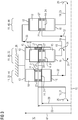
- FIG. 1 shows schematically the structure of a first embodiment of the claimed coupling gear 10, which has a first, second and third planetary stage 20, 30, 40.
- the planetary stages 20, 30, 40 each have a ring gear 12, a planet carrier 14 with planet gears 18 accommodated therein and a sun gear 16 as the stage components 11.
- the stage components 11 mesh with one another and in each of the planetary stages 20, 30, 40 implement a single-stage planetary gear which rotates around a main axis of rotation 15 during operation.
- planetary gear axles 24, which are provided with bearings 27, are arranged on the planet carriers 14 of the planetary stages 20, 30, 40. A rotatable mounting of the planet gears 18 in the respective planet carriers 14 is thereby realized.
- the second planetary stage 30 At least two planet gears 18 are accommodated in the planet carrier 14 and are attached to different radial positions 28.
- a radially outer direction is in FIG. 1 represented by arrow 28.
- at least one radially inner planet gear 45 and one radially outer planet gear 47 are rotatably received in the planet carrier 14 of the second planetary stage 30.
- the radially inner planet gear 45 meshes with the sun gear 16 of the second planetary stage 30 and the radially outer planet gear 47.
- the radially outer planet gear 47 in turn meshes with the ring gear 12 of the second Planetary stage 30.
- the second planetary stage 30 is designed as a positive gear 22.
- the first and third planetary stages 20, 40 are designed as a minus gear 44.
- a drive power 25 is supplied via a first power shaft 21, which is designed as a sun shaft 19.
- the sun shaft 19 is connected to the planet carrier 14 of the first planetary stage 20.
- the planetary gear axles 24 of the first and second planetary stages 20, 30 are connected to one another via a coupling element 39, which is formed in one piece with the planetary gear axles 24 of the first and second planetary stages 20, 30.
- the first and second planetary gear stages 20, 30 form a common continuous planet gear axis 24.
- the ring gears 12 of the first and second planetary gear stages 20, 30 are also coupled to a stationary connection 26, so that the ring gears 12 of the first and second planetary gear stages 20, 30 are connected to a housing 17 of the coupling gear 10 are connected.
- the stationary connection 26 reduces the rotating masses in the coupling gear 10 and thus improves the smooth running of the coupling gear 10.
- the drive power 25 which is supplied to the first and second planetary stages 20, 30 via their planet carriers 14 or their planetary gear axles 24, is converted into a rotation of the sun gears 16 of the first and second planetary stages 20, 30 and their associated sunshafts 19 during operation .
- the first planetary stage 20 is designed as a minus gear and the second planetary stage 30 as a plus gear 22 and the first planetary stage as a minus gear 44, the directions of rotation 31 of the sun gears 19, and thus also of the corresponding sun shafts 19, are opposite. This is in FIG. 1 represented by the oppositely oriented arrows 31.
- the first and second planetary stages 20, 30 divide the drive power 25 into a first and a second sub-stage 32, 33.
- the first and second sub-stages 32, 33 are essentially of the same size and are brought together again via the third planetary stage 40.
- the sun shaft 19 of the first planetary stage 20 is connected to the planet carrier 14 of the third planetary stage 40 and the sun shaft 19 of the second planetary stage 30 is connected to the ring gear 12 of the third planetary stage 40. Because the ring gear 12 and the planet carrier 14 of the third planetary stage 40 have opposite directions of rotation 31, an increased speed is achieved at the sun gear 16 of the third planetary stage 40.
- the sun gear 16 of the third planetary stage 40 is connected to a sun shaft 19 of the third planetary stage 40, which serves as the second power shaft 23.
- an output power 29 is discharged which, taking mechanical losses into account, corresponds essentially to the drive power 25 which is fed to the coupling gear 10.
- the embodiment according to FIG. 1 also offers a particularly simple shaft connection and shaft bushing
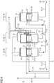
- FIG 2 the structure of a second embodiment of the claimed coupling drive 10 is shown schematically.
- the structure and functioning in FIG 2 essentially corresponds with FIG. 1 so the description of FIG. 1 essentially also for FIG 2 applies.
- the same reference numerals have in FIG. 1 and FIG 2 the same technical meaning.
- the ring gear 12 of the second planetary stage 30 has the largest outer diameter 42.
- the ring gears 12 of the first and second planetary stages 20, 30 have the same outer diameter.
- a further improved overall transmission ratio of the coupling gear 10 is thereby achieved.
- the fact that the ring gear 12 of the second planetary stage 30 has the largest outer diameter 42 makes this an advantageous one Suspension of the linkage 10 allows in a central area.
- the planet gears 18 in FIG 2 structurally identical, that is, interchangeable. This realizes the use of common parts, which allows more cost-effective production.
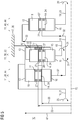
- FIG 3 shows a third embodiment of the claimed linkage 10.
- the ring gears 12 of the first and second planetary stage 20, 30 formed continuously and have the same outer diameter 42.
- the number of components is reduced by the integrally formed ring gears 12 in the first and second planetary stages 20, 30, which permits easier and faster assembly and production.
- FIG 4 shows a fourth embodiment of the claimed coupling gear 10, in which the second planetary stage 30 is stationary.
- the second planetary stage 30 is coupled to a stationary connection 26, which in turn is connected to the housing 17 of the coupling gear 10.
- the first power shaft 21, which is designed as a sun shaft 19, is connected to the ring gears 12 of the first and second planetary stages 20, 30.
- the ring gears 12 of the first and second planetary stages 20, 30 are connected to one another in a rotationally rigid manner via at least one connecting element 38.
- the connecting element 38 can be designed, for example, as a rod connection or flange connection.
- the coupling gear 10 is in the area of the first and second planetary stage 20, 30 can be formed without a housing, so that a weight saving is achieved.
- the planet gears are also in FIG 4 structurally identical.
- FIG. 5 A sixth embodiment of the claimed linkage 10 is shown in FIG FIG 5 displayed.
- the embodiment in FIG 6 corresponds essentially to the embodiments from FIGS 1 to 5 .
- the ring gears 12 of the first and second planetary stages 20, 30 are formed in one piece, that is to say continuously. This reduces the number of components in the coupling gear 10, which makes assembly easier and more economical.
- the one-piece ring gears 12 allow the coupling gear 10 to be designed without a housing in the region of the first and second planetary stages 20, 30. This saves weight.
- the integrally formed ring gears 12 of the first and second planetary stages 20, 30 have the largest outer diameter 42 of the three planetary stages 20, 30, 40. The largest outer diameter 42 is reduced compared to the gearboxes known from the prior art, which are designed for the same drive power. As a result, the power density in the claimed coupling drives 10 is further increased.
- FIG 6 shows in cross section schematically the structure of an embodiment of a first or second planetary stage 20, 30, which is designed as a positive gear 22.
- the positive gear 22 has a sun gear 16 which meshes with a plurality of planet gears 18, which in turn are each used as a radially inner planet gear 45.
- the positive gear 22 is centered about the main axis of rotation 15 of the coupling gear 10, not shown.
- Each of the radially inner planet gears 45 is arranged on a planet carrier 14 so as to be rotatable about a planet gear axis 26 by means of a bearing 27.
- Each radially inner planet gear 45 meshes with a further planet gear 18, which is the radially outer Planet gear 47 is formed and arranged.
- the radially outer planet gears 47 are each rotatably arranged on a planet gear axis 26 on the planet carrier 14 by means of a bearing 27.
- the radially outer planet gears 47 in turn mesh with a ring gear toothing 13 on a ring gear 12, which is also a gear component 11 of the positive gear 22.
- the radially outer planet gears 47 viewed in the circumferential direction 50, lie between two planet carrier webs 41.
- the radially outer planet gears 47 are arranged offset in the circumferential direction 50 with respect to the radially inner planet gears 45.
- the planet gear axles 26 of a radially inner planet gear 45, the radially outer planet gear 47 meshing therewith, and the main axis of rotation 15 form a triangular arrangement 43 , Furthermore, the triangular arrangement 43 enables the outer diameter 42 of the planetary stage 22 to be reduced.
- FIG 7 an embodiment of a wind turbine 70 according to the invention is shown in a sectional oblique view.
- the wind turbine 70 comprises a rotor 63 which can be rotated by the wind.
- the rotor 63 is connected to a transmission 66 in a torque-transmitting manner via a rotor shaft 62.
- the transmission 66 is in turn connected to a generator 64 in a torque-transmitting manner.
- the rotor shaft 62, the gear 66 and the generator 64 belong to a drive set 60 which is received in a nacelle 65 of the wind turbine 70.
- the transmission 66 is designed in accordance with one of the embodiments described above.
- the efficiency of the wind power plant 70 is increased by an appropriately designed gear 66.
- a stressed coupling gear 10 has a reduced diameter 42, which facilitates the assembly of the wind turbine 70.
- the industrial application 80 comprises a drive means 82 which is designed, for example, as an electric motor, as an internal combustion engine or as a hydraulic motor.
- the drive means 82 is coupled to a transmission 66, which is in turn connected to a mechanical application 84.
- the drive means 82 is designed to deliver a drive power 25, which is supplied to the transmission 66 via a second power shaft 23.
- the incoming drive power 25 is converted by the gear 66, taking into account friction losses, in terms of speed and torque, as an output power 29 via a first power shaft 21 to the mechanical application 84.
- the speed on the first power shaft 21 is lower than on the second power shaft 23.
- the gear 66 is designed as a coupling gear 10 according to one of the above-described embodiments.
- the mechanical application 84 can be configured as a mill, a vertical mill, a sugar mill, a cement mill, a rock breaker, a conveyor belt, a pump, a lifting device, a garbage or scrap press.
Landscapes
- Engineering & Computer Science (AREA)
- General Engineering & Computer Science (AREA)
- Mechanical Engineering (AREA)
- Life Sciences & Earth Sciences (AREA)
- Sustainable Development (AREA)
- Sustainable Energy (AREA)
- Chemical & Material Sciences (AREA)
- Combustion & Propulsion (AREA)
- Retarders (AREA)
Priority Applications (1)
| Application Number | Priority Date | Filing Date | Title |
|---|---|---|---|
| EP18184998.5A EP3599391A1 (fr) | 2018-07-23 | 2018-07-23 | Engrenage couplé pour éoliennes et applications industrielles |
Applications Claiming Priority (1)
| Application Number | Priority Date | Filing Date | Title |
|---|---|---|---|
| EP18184998.5A EP3599391A1 (fr) | 2018-07-23 | 2018-07-23 | Engrenage couplé pour éoliennes et applications industrielles |
Publications (1)
| Publication Number | Publication Date |
|---|---|
| EP3599391A1 true EP3599391A1 (fr) | 2020-01-29 |
Family
ID=63035931
Family Applications (1)
| Application Number | Title | Priority Date | Filing Date |
|---|---|---|---|
| EP18184998.5A Withdrawn EP3599391A1 (fr) | 2018-07-23 | 2018-07-23 | Engrenage couplé pour éoliennes et applications industrielles |
Country Status (1)
| Country | Link |
|---|---|
| EP (1) | EP3599391A1 (fr) |
Cited By (1)
| Publication number | Priority date | Publication date | Assignee | Title |
|---|---|---|---|---|
| US12391373B2 (en) * | 2022-09-16 | 2025-08-19 | Safran Transmission Systems | Speed reducer for a device for driving a wheel of an aircraft landing gear |
Citations (4)
| Publication number | Priority date | Publication date | Assignee | Title |
|---|---|---|---|---|
| DE19963597A1 (de) | 1999-12-23 | 2001-07-26 | Mannesmann Ag | Getriebe, insbesondere für Windkraftanlagen |
| DE102012217509A1 (de) | 2012-09-27 | 2014-03-27 | Zf Friedrichshafen Ag | Getriebeeinheit mit Zahnradträger |
| WO2014082782A1 (fr) * | 2012-11-29 | 2014-06-05 | Zf Friedrichshafen Ag | Unité de transmission dotée d'un train planétaire positif |
| DE102013216802A1 (de) | 2013-08-23 | 2015-02-26 | Schaeffler Technologies Gmbh & Co. Kg | Hochübersetzendes Umlaufrädergetriebe, insbesondere Stell- oder Aktuatorgetriebe |
-
2018
- 2018-07-23 EP EP18184998.5A patent/EP3599391A1/fr not_active Withdrawn
Patent Citations (5)
| Publication number | Priority date | Publication date | Assignee | Title |
|---|---|---|---|---|
| DE19963597A1 (de) | 1999-12-23 | 2001-07-26 | Mannesmann Ag | Getriebe, insbesondere für Windkraftanlagen |
| DE102012217509A1 (de) | 2012-09-27 | 2014-03-27 | Zf Friedrichshafen Ag | Getriebeeinheit mit Zahnradträger |
| EP2901012A1 (fr) * | 2012-09-27 | 2015-08-05 | ZF Friedrichshafen AG | Bloc d'engrenages avec porte-pignons |
| WO2014082782A1 (fr) * | 2012-11-29 | 2014-06-05 | Zf Friedrichshafen Ag | Unité de transmission dotée d'un train planétaire positif |
| DE102013216802A1 (de) | 2013-08-23 | 2015-02-26 | Schaeffler Technologies Gmbh & Co. Kg | Hochübersetzendes Umlaufrädergetriebe, insbesondere Stell- oder Aktuatorgetriebe |
Cited By (1)
| Publication number | Priority date | Publication date | Assignee | Title |
|---|---|---|---|---|
| US12391373B2 (en) * | 2022-09-16 | 2025-08-19 | Safran Transmission Systems | Speed reducer for a device for driving a wheel of an aircraft landing gear |
Similar Documents
| Publication | Publication Date | Title |
|---|---|---|
| DE102017107803B3 (de) | Antriebsvorrichtung für ein Kraftfahrzeug | |
| EP3587863A1 (fr) | Engrenage planétaire, chaîne cinématique, éolienne et application industrielle | |
| DE102012217509A1 (de) | Getriebeeinheit mit Zahnradträger | |
| DE102006057055B3 (de) | Leistungsverzweigtes Windkraftgetriebe | |
| DE102018101270A1 (de) | Antriebsvorrichtung mit einer elektrischen Maschine | |
| DE102019102994A1 (de) | Fahrzeugantriebssystem | |
| DE102018111807A1 (de) | Antriebsvorrichtung mit einer elektrischen Antriebsmaschine | |
| DE102016118877A1 (de) | Mechanische Getriebeanordnung | |
| DE102012221823A1 (de) | Getriebeeinheit mit Plusgetriebesatz | |
| DE102013214618A1 (de) | Getriebe für ein Kraftfahrzeug | |
| DE102018111798A1 (de) | Antriebsvorrichtung mit einer elektrischen Maschine | |
| EP3767102B1 (fr) | Ensemble de train d'entrainement | |
| WO2020015965A1 (fr) | Transmission de bateau et système d'entraînement pour une propulsion de bateau | |
| DE102012221825A1 (de) | Getriebeeinheit mit Plusgetriebesatz | |
| DE102011118832A1 (de) | Planetengetriebe mit einem Getriebegehäuse | |
| EP3961066A1 (fr) | Train épicycloïdal à distribution améliorée du lubrifiant, chaine cinématique, éolienne et application industrielle | |
| DE102022206034A1 (de) | Getriebe für einen Antriebsstrang | |
| EP3599393A1 (fr) | Engrenage couplé pour éoliennes et applications industrielles | |
| EP3599391A1 (fr) | Engrenage couplé pour éoliennes et applications industrielles | |
| EP3507485A1 (fr) | Moyeu pour pale d'hélice d'une éolienne, et éolienne doté de ce moyeu | |
| WO2019121111A1 (fr) | Engrenage planétaire présentant une structure de soutien améliorée, chaîne cinématique et éolienne | |
| DE102022206043A1 (de) | Getriebe für einen Antriebsstrang | |
| DE102010010201A1 (de) | Windkraftanlage mit Getriebe/Generator-Baueinheit | |
| DE102020108315A1 (de) | Getriebeanordnung für Windkraftanlagen | |
| DE102020125690A1 (de) | Antriebssystem |
Legal Events
| Date | Code | Title | Description |
|---|---|---|---|
| PUAI | Public reference made under article 153(3) epc to a published international application that has entered the european phase |
Free format text: ORIGINAL CODE: 0009012 |
|
| STAA | Information on the status of an ep patent application or granted ep patent |
Free format text: STATUS: THE APPLICATION HAS BEEN PUBLISHED |
|
| AK | Designated contracting states |
Kind code of ref document: A1 Designated state(s): AL AT BE BG CH CY CZ DE DK EE ES FI FR GB GR HR HU IE IS IT LI LT LU LV MC MK MT NL NO PL PT RO RS SE SI SK SM TR |
|
| AX | Request for extension of the european patent |
Extension state: BA ME |
|
| STAA | Information on the status of an ep patent application or granted ep patent |
Free format text: STATUS: THE APPLICATION IS DEEMED TO BE WITHDRAWN |
|
| 18D | Application deemed to be withdrawn |
Effective date: 20200730 |