EP3599493A2 - Appareil d'imagerie - Google Patents
Appareil d'imagerie Download PDFInfo
- Publication number
- EP3599493A2 EP3599493A2 EP19187690.3A EP19187690A EP3599493A2 EP 3599493 A2 EP3599493 A2 EP 3599493A2 EP 19187690 A EP19187690 A EP 19187690A EP 3599493 A2 EP3599493 A2 EP 3599493A2
- Authority
- EP
- European Patent Office
- Prior art keywords
- heat
- board
- imaging apparatus
- attached
- contact
- Prior art date
- Legal status (The legal status is an assumption and is not a legal conclusion. Google has not performed a legal analysis and makes no representation as to the accuracy of the status listed.)
- Granted
Links
Images






Classifications
-
- H—ELECTRICITY
- H04—ELECTRIC COMMUNICATION TECHNIQUE
- H04N—PICTORIAL COMMUNICATION, e.g. TELEVISION
- H04N23/00—Cameras or camera modules comprising electronic image sensors; Control thereof
- H04N23/50—Constructional details
-
- G—PHYSICS
- G02—OPTICS
- G02B—OPTICAL ELEMENTS, SYSTEMS OR APPARATUS
- G02B7/00—Mountings, adjusting means, or light-tight connections, for optical elements
- G02B7/008—Mountings, adjusting means, or light-tight connections, for optical elements with means for compensating for changes in temperature or for controlling the temperature; thermal stabilisation
-
- H—ELECTRICITY
- H05—ELECTRIC TECHNIQUES NOT OTHERWISE PROVIDED FOR
- H05K—PRINTED CIRCUITS; CASINGS OR CONSTRUCTIONAL DETAILS OF ELECTRIC APPARATUS; MANUFACTURE OF ASSEMBLAGES OF ELECTRICAL COMPONENTS
- H05K7/00—Constructional details common to different types of electric apparatus
- H05K7/20—Modifications to facilitate cooling, ventilating, or heating
- H05K7/2039—Modifications to facilitate cooling, ventilating, or heating characterised by the heat transfer by conduction from the heat generating element to a dissipating body
- H05K7/20436—Inner thermal coupling elements in heat dissipating housings, e.g. protrusions or depressions integrally formed in the housing
-
- G—PHYSICS
- G03—PHOTOGRAPHY; CINEMATOGRAPHY; ANALOGOUS TECHNIQUES USING WAVES OTHER THAN OPTICAL WAVES; ELECTROGRAPHY; HOLOGRAPHY
- G03B—APPARATUS OR ARRANGEMENTS FOR TAKING PHOTOGRAPHS OR FOR PROJECTING OR VIEWING THEM; APPARATUS OR ARRANGEMENTS EMPLOYING ANALOGOUS TECHNIQUES USING WAVES OTHER THAN OPTICAL WAVES; ACCESSORIES THEREFOR
- G03B17/00—Details of cameras or camera bodies; Accessories therefor
- G03B17/55—Details of cameras or camera bodies; Accessories therefor with provision for heating or cooling, e.g. in aircraft
-
- H—ELECTRICITY
- H04—ELECTRIC COMMUNICATION TECHNIQUE
- H04N—PICTORIAL COMMUNICATION, e.g. TELEVISION
- H04N23/00—Cameras or camera modules comprising electronic image sensors; Control thereof
- H04N23/50—Constructional details
- H04N23/51—Housings
-
- H—ELECTRICITY
- H04—ELECTRIC COMMUNICATION TECHNIQUE
- H04N—PICTORIAL COMMUNICATION, e.g. TELEVISION
- H04N23/00—Cameras or camera modules comprising electronic image sensors; Control thereof
- H04N23/50—Constructional details
- H04N23/52—Elements optimising image sensor operation, e.g. for electromagnetic interference [EMI] protection or temperature control by heat transfer or cooling elements
-
- H—ELECTRICITY
- H04—ELECTRIC COMMUNICATION TECHNIQUE
- H04N—PICTORIAL COMMUNICATION, e.g. TELEVISION
- H04N23/00—Cameras or camera modules comprising electronic image sensors; Control thereof
- H04N23/50—Constructional details
- H04N23/54—Mounting of pick-up tubes, electronic image sensors, deviation or focusing coils
-
- H—ELECTRICITY
- H04—ELECTRIC COMMUNICATION TECHNIQUE
- H04N—PICTORIAL COMMUNICATION, e.g. TELEVISION
- H04N23/00—Cameras or camera modules comprising electronic image sensors; Control thereof
- H04N23/50—Constructional details
- H04N23/55—Optical parts specially adapted for electronic image sensors; Mounting thereof
-
- G—PHYSICS
- G02—OPTICS
- G02B—OPTICAL ELEMENTS, SYSTEMS OR APPARATUS
- G02B13/00—Optical objectives specially designed for the purposes specified below
- G02B13/06—Panoramic objectives; So-called "sky lenses" including panoramic objectives having reflecting surfaces
-
- G—PHYSICS
- G03—PHOTOGRAPHY; CINEMATOGRAPHY; ANALOGOUS TECHNIQUES USING WAVES OTHER THAN OPTICAL WAVES; ELECTROGRAPHY; HOLOGRAPHY
- G03B—APPARATUS OR ARRANGEMENTS FOR TAKING PHOTOGRAPHS OR FOR PROJECTING OR VIEWING THEM; APPARATUS OR ARRANGEMENTS EMPLOYING ANALOGOUS TECHNIQUES USING WAVES OTHER THAN OPTICAL WAVES; ACCESSORIES THEREFOR
- G03B17/00—Details of cameras or camera bodies; Accessories therefor
- G03B17/02—Bodies
-
- G—PHYSICS
- G03—PHOTOGRAPHY; CINEMATOGRAPHY; ANALOGOUS TECHNIQUES USING WAVES OTHER THAN OPTICAL WAVES; ELECTROGRAPHY; HOLOGRAPHY
- G03B—APPARATUS OR ARRANGEMENTS FOR TAKING PHOTOGRAPHS OR FOR PROJECTING OR VIEWING THEM; APPARATUS OR ARRANGEMENTS EMPLOYING ANALOGOUS TECHNIQUES USING WAVES OTHER THAN OPTICAL WAVES; ACCESSORIES THEREFOR
- G03B37/00—Panoramic or wide-screen photography; Photographing extended surfaces, e.g. for surveying; Photographing internal surfaces, e.g. of pipe
- G03B37/04—Panoramic or wide-screen photography; Photographing extended surfaces, e.g. for surveying; Photographing internal surfaces, e.g. of pipe with cameras or projectors providing touching or overlapping fields of view
Definitions
- Embodiments of the present disclosure relate to an imaging apparatus, and particularly to a heat dissipation structure of the imaging apparatus provided with an image sensor.
- JP-6218469-B JP-2015-023343-B discloses the technology that dissipates heat generated by the image sensor through a flexible heat dissipation sheet disposed to thermally connects the exterior component of the outer surface of the imaging apparatus with the image sensor.
- the heat dissipation sheet is used to guide the heat generated by the image sensor to the exterior component.
- JP-6218469-B has a description of the heat dissipation structure in which one end of the heat dissipation sheet 24 is attached to the rigid portion 201 of the sensor substrate 20 to constitute a thermal connection between the heat dissipation sheet 24 and the sensor substrate 20, and the other end of the heat dissipation sheet 24 is folded in the direction of the optical axis at the folded portion 241 and attached to the back side of the front cover 40 to constitute a heat connection between the heat dissipation sheet 24 and the front cover 40.
- the heat dissipation structure of JP-6218469-B fails to efficiently dissipate heat.
- an imaging apparatus including an exterior component; an image sensor disposed inside the exterior component, the image sensor including a board; a sheet body attached to the image sensor to dissipate heat generated by the image sensor; an elastic body configured to support the sheet body; and a holder configured to hold the elastic body.
- the sheet body includes a heat receiver attached to the board of the image sensor; and a heat dissipating section attached to the elastic body.
- the elastic body is compressively deformable between the exterior component and the holder to compress the heat dissipating section against an inner surface of the exterior component.
- an improved imaging apparatus including an exterior component; an image sensor, the image sensor including a board disposed inside the exterior component; and a sheet body attached to the image sensor.
- the sheet body is configured to dissipate heat generated by the image sensor.
- the imaging apparatus further includes a holder configured to hold the sheet body, and an elastic body being elastically deformable and having thermal conductivity.
- the sheet body includes a heat receiver attached to the board of the image sensor, and a heat dissipating section attached to the elastic body.
- the elastic body is held by the holder and being compressively deformable to be compressed against an inner surface of the exterior component.
- a heat-dissipation sheet is compressed against the inner surface of an external component using the restoring force of an elastic member so as to constitute a thermal connection between the heat-dissipation sheet and the external member. Accordingly, the heat generated by the image sensor can be efficiently dissipated to the external component.
- An imaging apparatus 10 includes an optical unit 11 (see FIG. 3 ) formed by symmetrically combining two lens barrels 11A and 11B having the same shape.
- Each of the lens barrel 11A and 11B includes an imaging optical system that ranges from a front group F on the object side to an imaging plane IP of image sensors 12A and 12B.
- the imaging optical system light from an object is led to and formed on the imaging plane IP of the corresponding image sensor 12A/12B.
- the barrels 11A and the barrels 11B are combined such that the front groups F of the respective lens barrels 11A and 11B face in opposite directions from each other, and the optical axes of the front groups F are coaxially aligned.
- the image sensor 12A of the lens barrel 11A is disposed with the imaging plane IP facing the left
- the image sensor 12B of the lens barrel 11B is disposed with the imaging plane IP facing the right.
- the image sensors 12A and 12B are supported by image-sensor boards 13A and 13B, respectively.
- the image sensor 12A and the image-sensor board 13A are combined to form an image-sensor unit 14A.
- the image sensor 12B and the image-sensor board 13B are combined to form an image-sensor unit 14B.
- FIGs. 4A and 4B indicate the image-sensor unit 14B.
- the image-sensor unit 14A and the image-sensor unit 14B constitute a symmetrical configuration along the right-to-left direction.
- a flexible board 15 is connected to a connector disposed in the vicinity of the lower ends of the image-sensor boards 13A and 13B.
- the lens barrels 11A and 11B are disposed such that the board surfaces (BS) (surfaces on the opposite side of the imaging planes IP of the image sensors 12A and 12B) of the image-sensor boards 13A and 13B face each other. That is, the image-sensor units 14A and 14B are disposed to face in the opposite directions.
- An object image (an image of an object) formed by each of the imaging optical systems of the lens barrels 11A and 11B is formed on the imaging plane IP of each of the image sensors 12A and 12B, and photoelectrically converted into an image signal.
- the image signals are then transmitted from the image-sensor boards 13A and 13B to a first board 60 (see FIGs. 20 , 23 , and 25 ) disposed within the imaging apparatus 10 through the flexible board 15.
- the imaging optical system of each of the lens barrels 11A and 11B has an angle of view wider than 180 degrees, and is an all-round (circumferential) fisheye lens whose image circle fits within the imaging plane IP of each of the image sensors 12A and 12B.
- the optical unit 11 is configured as a spherical imaging system to generate an image with a solid angle of 4 ⁇ steradian by combining two images formed by the image sensors 12A and 12B of the lens barrels 11A and 11B.
- the imaging optical system of each of the lens barrels 11A and 11B is configured to be thin in the front-to-back direction by bending the optical path multiple times using a plurality of prisms.
- the lens barrels 11A and 11B are disposed such that the image-sensor units 14A and 14B face in the opposite directions along the right-to-left direction, and such that the shorter side of each imaging plane IP is along the front-to-back direction, and the longer side longer than the shorter side of each imaging plane IP of the image sensors 12A and 12B is along the up-to-down direction.
- the optical unit 11 as a whole including the two lens barrels 11A and 11B can be made thinner along the front-to-back direction. Accordingly, the parallax between the lens barrels 11A and 11B can be reduced, and higher-quality spherical images can be obtained.
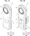
- the imaging apparatus 10 includes a front cover 20 and a rear cover 21 as exterior components constituting the outer surface of the imaging apparatus 10.
- the front cover 20 and the rear cover 21 are both made of metal, such as magnesium and aluminum. As illustrated in FIGs. 1A and 1B , the front cover 20 and the rear cover 21 have a substantially symmetrical shape along the front-to-back direction.
- the imaging apparatus 10 includes a shutter button 22 slightly below the intermediate portion of the rear face along the up-to-down direction.
- the imaging apparatus 10 has an opening in the rear cover 21 to enable the shutter button 22 to be exposed to the outside of the imaging apparatus 10.
- the shutter button 22 is an operation member serving as a trigger for imaging (including both still image capturing and moving image capturing).
- the imaging apparatus 10 further includes a display unit 24 below the shutter button 22, configured to display several pieces of information for, for example, an operation screen and a setting screen.
- the display unit 24 can be configured of, for example, an organic EL display.
- the imaging apparatus 10 further includes a power button 28 at the intermediate portion of the right face along the up-to-down direction.
- the power button 28 serves as an operation member for switching on and off the imaging apparatus 10.
- the imaging apparatus 10 further includes a plurality of operation buttons 29 below the power button 28, to operate setting the image-capturing mode or the wireless connection mode.
- the imaging apparatus 10 is communicable with external devices, such as a personal computer (PC), through the external connector 16 provided at the lower end of the imaging apparatus 10.
- PC personal computer
- the imaging apparatus 10 is long in the up-to-down direction, and has two sections arranged along the up-and-down direction within the imaging apparatus 10 as illustrated in FIG. 2 .
- the upper section houses the optical unit 11.
- the lower section houses a battery 23, a first board 60 and a second board 61 (see FIGs. 20 and 23 ) for control.
- built-in components, such as the optical unit 11 and the battery 23 are attached to the rear-cover 21 side (see FIG. 2 ), and the front cover 20 is attached (screwed) to the rear cover 21 with a screw.
- Each of the front cover 20 and the rear cover 21 includes a contact configured to determine the relative positions of the front cover 20 and the rear cover 21 along the front-to-back direction.
- the structure of the inner surface of the rear cover 21 is illustrated in FIGs. 5 , 6 , and 8 .
- the rear cover 21 has a shape of a plate elongated in the up-to-down direction, and has a lens opening 21a to enable the front group F of the lens barrel 11B to be exposed to the outside of the imaging apparatus 10.
- a metal frame formed of a side plates 25 and 26, and a transverse plate 27 is disposed on the inner surface of the rear cover 21, a metal frame formed of a side plates 25 and 26, and a transverse plate 27 is disposed.
- the side plates 25 and 26 and the transverse plate 27 are all made of metal, and are attached to the rear cover 21 and the front cover 20. This configuration enhances the rigidity of the imaging apparatus 10.
- the side plate 25 extends along the up-to-down direction at the right edge of the rear cover 21, and is screwed to the rear cover 21 with a plurality of screws at different positions along the up-to-down direction. More specifically, as illustrated in FIG. 5 , plate-shaped fastening sections 21b projecting forward are disposed close to (near) the right edge of the rear cover 21.
- the side plate 25 is screwed to the fastening sections 21b with a plurality of screws 73 at different positions. Specifically, the upper end and the lower end of the side plate 25 are screwed to the fastening sections 21b.
- the side plate 26 extends along the up-to-down direction at the left edge of the rear cover 21, and is screwed to the rear cover 21 with a plurality of screws at different positions along the up-to-down direction. More specifically, as illustrated in FIG. 6 , plate-shaped fastening sections 21c projecting forward are disposed close to (near) the right edge of the rear cover 21.
- the side plate 26 is screwed to the fastening sections 21c with a plurality of screws 74 at different positions. Specifically, the upper end and the lower end of the side plate 26 are screwed to the fastening sections 21c.
- the side plates 25 and 26 are also screwed to the front cover 20 after the front cover 20 is attached to the rear cover 21. With this configuration, the side plates 25 and 26 are attached to (screwed to) the rear cover 21 and the front cover 20, which allows for heat transfer between the metals in contact with each other.
- the side plate 25 and the side plate 26 are provided with fastening sections 25a and 26a located midway along the up-to-down direction (the longitudinal direction of the side plates 25 and the side plate 26), respectively.
- the fastening section 25a has a shape that projects upward (to the front indicated by arrow in FIG. 5 ) from the body of the side plate 25 and bends to the left.
- the fastening section 26a has a shape that projects upward (to the front indicated by arrow in FIG. 6 ) from the body of the side plate 26 and bends to the right.
- the bending portions of the fastening sections 25a and 26a are attached to the right-to-left directional ends of the transverse plate 27 using the screws 70.
- the transverse plate 27 extends right-to-left direction to connect the side plate 25 and the side plate 26.
- a front plate 27a of the transverse plate 27 is attached to the fastening sections 25a and 26a with the screws 70.
- the front and back faces of the front plate 27a face in the front-to-back direction of the imaging apparatus 10.
- a dividing plate 27b of the transverse plate 27 extends rearward from the lower edge of the front plate 27a, and the front and back faces of the dividing plate 27b face up-to-down direction of the imaging apparatus 10.
- the dividing plate 27b divides the interior space of the imaging apparatus 10 into two sections in the up-to-down direction.
- the transverse plate 27 further includes a bottom plate 27c that extends downward from the rear edge of the dividing plate 27b.
- the front and back faces of the bottom plate 27c face in the front-to-back direction, and the battery 23 is disposed on the front side of the bottom plate 27c (see FIG. 2 ).
- the image-sensor units 14A and 14B including large image sensors 12A and 12B are arranged close to each other, facing in the opposite directions.
- the casing is thin in the front-to-back direction.
- a heat-dissipation structure is provided to efficiently dissipate the heat generated from the image sensors 12A and 12B.
- the heat-dissipation structure in the imaging apparatus 10 is described.
- the heat-dissipation structure of the imaging apparatus 10 enables heat generated from the image-sensor units 14A and 14B to be dissipated to the front cover 20 and the rear cover 21, which are the exterior components, using a heat dissipation sheet 30 a heat dissipator.
- a heat dissipation sheet 30A is provided for the image-sensor unit 14A
- a heat dissipation sheet 30B is provided for the image-sensor unit 14B.
- the heat dissipation sheet 30A and the heat dissipation sheet 30B have the same structure except for, for example, a bending direction.
- the heat dissipation sheet 30A and the heat dissipation sheet 30B are individually referred to as to describe the differences between the heat dissipation sheet 30A and the heat dissipation sheet 30B but are referred to collectively as the heat dissipation sheet 30 to describe the common features.
- the heat dissipation sheet 30 (sheet body) is a flexible sheet made of material advantageous in heat conductivity.
- the heat dissipation sheet 30 is preferably made of graphite.
- the heat dissipation sheet 30 includes a heat receiver 31 attached to the back of the image-sensor board 13, an interposer 32 that extends from the heat receiver 31, and a heat dissipating section 33 disposed at the end of the interposer 32.
- An adhesive layer is formed on one side of the heat dissipation sheet 30.
- the adhesive layer is formed on the side surface of the heat dissipation sheet 30 illustrated in FIG. 4A , and not formed on the side surface of the heat dissipation sheet 30 illustrated in FIG. 4B .
- the front face is a non-adhesive-layer side at which the adhesive layer is not formed
- the back face is an adhesive-layer side at which the adhesive layer is formed.
- the heat receiver 31 has a stripe shape that is elongated up-to-down direction.
- the back face of the heat receiver 31, i.e., the adhesive layer, is attached to the back face of the image-sensor board 13 such that the heat receiver 31 is positioned near the center of the back face of the image-sensor board 13 in the front-to-back direction while extending along the up-to-down direction.
- the interposer 32 has a strip shape elongated in the front-to-back direction.
- the lower edge of the heat receiver 31 is connected to the interposer 32 at a position near the center of the interposer 32 in the longitudinal direction (the front-to-back direction).
- the interposer 32 also has the adhesive layer on the back face attached to the back face of the image-sensor board 13.
- the heat dissipating section 33 extends from the front edge of the interposer 32.
- the interposer 32 is connected to the heat dissipating section 33 at a position near the lower end of the heat dissipating section 33.
- a bending section 34 is provided between the interposer 32 and the heat dissipating section 33. In the initial state of the heat dissipation sheet 30, the bending section 34 is not bent, and the heat dissipating section 33 has a shape that significantly projects forward beyond the image sensor 12 and the image-sensor board 13 (see FIGs. 4A and 4B ). When the bending section 34 is bent, the front and back faces of the heat dissipating section 33 face in the front-to-back direction.
- the heat dissipation sheet 30A connected to the image-sensor unit 14A and the heat dissipation sheet 30B connected to the image-sensor unit 14B are bent in opposite directions.
- the bending section 34 of the heat dissipation sheet 30A connected to the image-sensor board 13A is configured to bend to the left (the image-sensor 12A side).
- the bending section 34 of the heat dissipation sheet 30B connected to the image-sensor board 13B is configured to bend to the right (the image-sensor 12B side).
- the heat dissipating section 33A and the heat dissipating section 33B are arranged in parallel with each other along right-to-left direction.
- the heat dissipation sheet 30A and the heat dissipation sheet 30B are symmetrically disposed along right-to-left direction when the bending sections 34 are bent. Bending of the bending sections 34 orients the front face and the back face of the heat dissipating section 33 of each of the heat dissipation sheets 30A and 30B to the front and the back, respectively.
- the bending line of the bending section 34 extends in the up-to-down direction while tilting in the front-to-back direction.
- This configuration provides a tilted shape (see FIG. 7 ) in which the amount of projection of the heat dissipating section 33 changes in the front-to-back direction, according to the position along the up-to-down direction when the bending section 34 is bent.
- the distal end (the upper end) of the heat dissipating section 33 projects to the front further than the proximal end (lower end) of the heat dissipating section 33 connected to the interposer 32 does.
- the adhesive layer on the back of the heat dissipating section 33 is attached to the front face of an elastic member 35 (elastic body).
- the elastic member 35 is elastically deformable, and is made of material advantageous in heat resistance.
- the elastic member 35 is supported by a base 36.
- the base 36 is a metal plate, and is screwed to a support 37 on the rear cover 21.
- the elastic member 35, the base 36, and the support 37 of the heat dissipation sheet 30A on the left is symmetrical with the elastic member 35, the base 36, and the support 37 of the heat dissipation sheet 30B on the right along the right-to-left direction.
- the base 36 which serves to support the heat dissipating section 33 on the heat-dissipation-sheet 30B side, projects upward (to the front as indicated by arrow in FIGs. 5 to 7 ) from the location at which the base is screwed to the support 37, and turns (bends) to the left.
- the bent base 36 has a support plate 36a positioned on the back of the elastic member 35 (see FIGs. 5 to 7 ).
- the base 36 which serves to support the heat dissipating section 33 on the heat-dissipation-sheet 30B side, projects upward (to the front as indicated by arrow in FIG. 2 ) from the location at which the base is screwed to the support 37, and turns (bends) to the right.
- the bent base 36 has a support plate 36a positioned on the back of the elastic member 35 (see FIG. 2 ).
- An adhesive layer is provided on the rear face of the elastic member 35 (the face opposite to the face to which the heat dissipating section 33 is attached).
- the elastic member 35 is attached to the front face of the support plate 36a via the adhesive layer.
- the lower end of the support plate 36a is superimposed on the front plate 27a of the transverse plate 27 in the front-to-back direction, and is support by the transverse plate 27 from the back side (see FIGs. 7 and 9 ). Accordingly, each of the left and right bases 36 is supported by the corresponding support 37 and transverse plate 27.
- FIG. 9 is an illustration of the cross-sectional structure in which the heat dissipating section 33, the elastic member 35, and the support plate 36a of the base 36 are disposed on top of each other.
- Each of the elastic member 35 and the support plate 36a has a tilted shape that corresponds to the above-described tilted shape of the heat dissipating section 33.
- the amount of forward projection on the upper-end side than the lower-end side does.
- the front cover 20 is attached to the rear cover 21 from the front side with the heat dissipation sheets 30A and 30B, which are connected with the image-sensor units 14A and 14B, supported by the elastic member 35 and the support plate 36a.
- the partially illustrated front cover 20 is attached to the rear cover 21.
- the elastic member 35 in FIG. 9 is not compressively deformed, that is, the elastic member 35 is at the first state.
- the heat dissipating section 33, the elastic member 35, and the support plate 36a are disposed on top of each other in the same direction as the direction (the front-to-back direction) in which the front cover 20 is attached to the rear cover 21.
- the inner surface of the front cover 20 contacts the front face of the heat dissipating section 33 to press the heat dissipating section 33 backward (to the back as indicated by arrow in FIG. 9 ) while compressing and deforming the elastic member 35.
- the compressed and deformed elastic member 35 provides a force to the heat dissipating section 33 due to the restoring action of the elastic member 35 so that the front surface of the heat dissipating section 33 is pressed against the inner surface of the front cover 20.
- the front surface of the heat dissipating section 33 comes into pressure (close) contact with the inner surface of the front cover 20. While the front cover 20 and the rear cover 21 are attached to each other, this pressure contact (compression) state is maintained, and the heat is effectively transferred from the heat dissipation sheet 30 to the front cover 20.
- This configuration enables the heat generated by the image sensor 12 to be dissipated to the exterior component, such as the front cover 20 made of metal, over a wide area using the heat dissipation sheet 30.
- the heat dissipating section 33 and the elastic member 35 are supported by the base 36 made of metal from the back side.
- the base 36 is supported by both the support 37 and the transverse plate 27, which provides an advantageous support strength. This configuration prevents the elastic member 35 from being deformed by a pressing force from the front cover 20 side. Accordingly, the heat dissipating section 33 can be kept compressed against the front cover 20. In other words, the heat dissipating section 33 can be prevented from being separated from the front cover 20.
- the imaging apparatus 10 enables the heat generated by the image sensors 12A and 12B to be dissipated to the front cover 20 made of metal through the heat dissipation sheets 30A and 30B, which means that the heat generated by the image sensors 12A and 12B disposed close to each other in a small space within the casing can be effectively dissipated.
- the heat dissipation sheets 30A and 30B that correspond to the image sensors 12A and 12B are disposed such that the front faces of the heat dissipating sections 33 face in the same direction (the front as indicated by arrow in the figures). With this arrangement, the front cover 20 is a shared target, to which heat is transferred, between the heat dissipation sheets 30A and 30B. Accordingly, complication of the heat-dissipation structure can be prevented.
- the heat receiver 31 of each of the heat dissipation sheets 30A and 30B is connected to the board surface (surface on the opposite side of the imaging plane IP of each of the image-sensor boards 13A and 13B).
- the board surface of the image-sensor unit 14A is opposed to the board surface of the image-sensor unit 14B.
- Such a configuration facilitates the heat dissipation sheet 30's dissipation of the heat between the image-sensor unit 14A and the image-sensor unit 14B, which can reduce the influence of heat between the image sensors 12A and 12B.
- the heat dissipating section 33 of each of the heat dissipation sheets 30A and 30B is not attached to the front cover 20, for example, by adhesive. Instead, the heat dissipating section 33 is brought into pressure (close) contact with the front cover 20 using the compressive deformation of the elastic member 35 in the direction in which the heat dissipating section 33 and the elastic member 35 are disposed when the front cover 20 is attached to the rear cover 21.
- This configuration eliminates a need for a certain operation to connect the heat dissipating section 33 to the front cover 20 in attaching the front cover 20 to the rear cover 21.
- the heat dissipating section 33 is merely separated from the front cover 20, and the heat dissipation sheets 30A and 30B remain on the rear cover 21 side without being damaged. In this configuration, there is no need to replace the heat dissipation sheet 30 with new one in removing the front cover 20.
- the above-described heat-dissipation structure that provides an advantageous heat-dissipation efficiency can be obtained.
- one end of the heat dissipation sheet 24 is attached to the rigid 201 of the sensor board 20, and the other end of the heat dissipation sheet 24 is attached to the back face of the front cover 40.
- Each attachment provides a thermal connection.
- the heat dissipation sheet 24 to have a sufficient length to attach the end of the heat dissipation sheet 24 to the back face of the front cover 40 before attaching the front cover 40 to the camera body.
- the heat-dissipation structure can reduce the space to be occupied by the heat dissipation sheets 30A and 30B while enabling the heat dissipating section 33 to be thermally connected to the front cover 20 at a proper position merely by attaching the front cover 20 to the rear cover 21.
- the front cover 20 can be freely attached and detached without damaging the heat dissipation sheets 30A and 30B, and the heat transfer from the heat dissipating section 33 can be reliably obtained when the front cover 20 is attached to the rear cover 21.
- the cost of parts can be reduced, and the labor and cost for the operation can also be reduced.
- the image-sensor units 14A and 14B are disposed close to each other such that the board surfaces of the image-sensor boards 13A and 13B are opposed to each other.
- an optical adjustment of the lens barrel 11A and the lens barrel 11B is to be performed in reattaching the optical unit 11, which takes a great amount of work.
- the heat-heat-dissipation structure according to an embodiment of the present disclosure, there is no need to replace the heat dissipation sheet 30 with new one when attaching and detaching the front cover 20. Thus, an increase in labor and cost can be prevented.
- the front cover 20 is attached to the rear cover 21 at the final stage of assembly after the internal structure of the imaging apparatus 10 including the optical unit 11 is held by the rear cover 21 (see FIG. 2 ).
- the state of the heat dissipating section 33 can be easily checked (bending and deformation states) immediately before attaching the front cover 20. Accordingly, the failure in heat dissipation can be prevented beforehand.
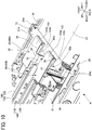
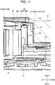
- FIGs. 10 and 11 are illustrations of the heat-dissipation structure according to a first modification.
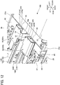
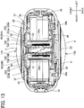
- FIGs. 12 to 16 are illustrations of the heat-dissipation structure according to a second modification.
- FIG. 17 is an illustration of the heat-dissipation structure according to a third modification.
- the same elements as those of the above-described embodiments are indicated with the same reference numerals, and description thereof is omitted.
- the parts not illustrated in the drawing have the same structure as those of the above-mentioned embodiment.
- each of the heat dissipation sheets 30A and 30B includes a heat dissipating section 133.
- the heat dissipating section 133 includes an exterior contact 133a and a frame contact 133b.
- the exterior contact 133a corresponds to the above-described heat dissipating section 33.
- the adhesive layer on the back face is attached to the front face of the elastic member 35, and no adhesive layer is formed on the front face of the exterior contact 133a.
- the position of the inner surface of the front cover 20, which is attached to the rear cover 21, is indicated by two-dot chain line in FIG. 11 .
- the exterior contact 133a is in the front of the inner surface of the front cover 20.
- the frame contact 133b is formed by bending the lower end of the exterior contact 133a backward and further folding it upward to form a U shape.
- the frame contact 133b is disposed between the support plate 36a of the base 36 and the front plate 27a of the transverse plate 27.
- An adhesive layer is formed on the back face of the frame contact 133b (the back face of the frame contact 133b faces the front because the frame contact 133b is folded upward), extending over the back face of the exterior contact 133a.
- the adhesive layer of the frame contact 133b is attached to the back face of the support plate 36a.
- the front face of the frame contact 133b (which faces backward because the frame contact 133b is folded backward) faces the front face of the front plate 27a.
- An adhesive layer is not formed on the front face of the frame contact 133b, which means that the frame contact 133b is not attached to the front plate 27a.
- the front plate 27a is a part to support the lower end of the support plate 36a of the base 36.
- the support plate 36a at the back of the elastic member 35 is pressed backward.
- the pressing of the support plate 36a causes the lower end of the support plate 36a to press the frame contact 133b backward so that the frame contact 133b comes into pressure contact with (compressed against) the front plate 27a.
- This configuration forms another heat-transfer path from the frame contact 133b to the transverse plate 27, in addition to the above-described heat-transfer path from the exterior contact 133a to the front cover 20.
- the transverse plate 27 is fastened to the side plates 25 and the side plate 26, and the side plates 25 and the side plate 26 are fastened to the rear cover 21 and the front cover 20.
- This configuration can dissipate heat to the rear cover 21 and the front cover 20 through the metal frame (the side plates 25, the side plate 26, and the transverse plate 27) within the casing, which can increase the heat dissipation property.
- the frame contact 133b is configured to be held between the support plate 36a and the front plate 27a when the front cover 20 is attached to the rear cover 21.
- the frame contact 133b can be reliably maintained in contact with the transverse plate 27 to which the heat is to be dissipated same as the exterior contact 133a and the heat dissipating section 33, without attaching the frame contact 133b to the transverse plate 27 by, for example, adhesive.
- the front cover 20 as well as the transverse plate 27 can be removed without any damage on the heat dissipating section 133, which can reduce the time and cost for replacement of the heat dissipation sheet 30.
- the casing of the imaging apparatus 10 further includes a heat storage member 40 (heat storage body) to which heat is transferred from the heat dissipation sheets 30A and 30B.
- the heat storage member 40 is made of material having a high heat storage property (large heat-storage capacity and good heat-absorption efficiency).
- a pair of right and left heat storage members 40 is disposed at positions adjacent to and below the positions of the left and right supports 37, respectively.
- a pair of right and left bases 38 is screwed to the right and left supports 37.
- Each base 38 is made of a metal plate material, and includes a side wall 38a and a bottom wall 38b (see FIG. 16 ).
- the side wall 38a surrounds the sides of a corresponding heat storage member 40, and the bottom wall 38b supports the back face of a corresponding heat storage member 40.
- the front-face side of the base 38 is open, and the front face of the heat storage member 40 is exposed forward.
- the base 38 and the heat storage member 40 constitute a holder to hold the elastic member 35 (see FIG. 15 ).
- Each of the heat dissipation sheets 30A and 30B includes a heat dissipating section 233.
- the heat dissipating section 233 includes an exterior contact 233a and a heat storage member contact 233b (heat storage body contact).
- the exterior contact 233a corresponds to the above-described heat dissipating section 33 according to an embodiment and the exterior contact 133a according to the first modification.
- the adhesive layer on the back face is attached to the front face of the elastic member 35, and no adhesive layer is formed on the front face of the exterior contact 233a.
- the heat storage member contact 233b is formed by bending backward the side end (the left end of the heat dissipation sheet 30A and the right end of the heat dissipation sheet 30B) of the exterior contact 233a, and folding the bent side end to face the back side of the exterior contact 233a, so as to form a U shape.
- the heat storage member contact 233b is disposed between the back face of the elastic member 35 and the front face of the heat storage member 40.
- An adhesive layer is formed on the back face of the heat storage member contact 233b (the back face of the heat storage member contact 233b faces the front because the heat storage member contact 233b is folded upward), extending over the back face of the exterior contact 233a.
- the adhesive layer of the heat storage member contact 233b is attached to the back face of the elastic member 35.
- the front face of the heat storage member contact 233b (which faces backward because the heat storage member contact 233b is folded backward) faces the front face of the heat storage member 40.
- An adhesive layer is not formed on the heat storage member contact 233b, which means that the heat storage member contact 233b is not attached to the heat storage member 40.
- FIGs. 13 and 14 are illustrations of the position of the exterior contact 233a when the front cover 20 is not attached to the rear cover 21, that is, at the first state of the elastic member 35 that is not compressively deformed.
- the exterior contact 233a is positioned in the front of the inner surface of the front cover 20.
- the exterior contact 233a of each of the heat dissipation sheets 30A and 30B is brought into contact with the inner surface of the front cover 20, which presses the exterior contact 233a backward.
- the elastic member 35 is held (supported) by the heat storage member 40 and the base 38, and the backward movement of the elastic member 35 is restricted.
- the elastic member 35 when the exterior contact 233a is pressed against the elastic member 35, the elastic member 35 is compressed and deformed to cause the exterior contact 233a to close contact (be compressed against) the inner surface of the front cover 20. As a result, a heat-transfer path is formed to transfer neat from the exterior contact 233a to the front cover 20, so as to enable the heat generated by the image sensors 12A and 12B to be dissipated to the front cover 20.
- the heat storage member contact 233b is configured to be compressed and held between the elastic member 35 and the heat storage member 40 when the front cover 20 is attached to the rear cover 21.
- the exterior contact 233a can be reliably maintained in contact with the heat storage member 40 to which the heat is to be dissipated same as the exterior contact 233a and the heat dissipating section 33, without attaching the heat storage member contact 233b to the heat storage member 40 by, for example, adhesive.
- the front cover 20 as well as the heat storage member 40 can be removed without any damage on the heat dissipating section 233, which can reduce the time and cost for replacement of the heat dissipation sheet 30.
- the shape (a component, such as the support plate 36a of the base 36, as illustrated in FIG. 7 ) to be connected to the transverse plate 27 is added to the base 38 so as to facilitate a dissipation of the heat of the heat storage member 40 from the base 38 to the metal frame (the side plates 25 and 26, and the transverse plate 27).
- the imaging apparatus 10 has the configuration in which the elastic member 35 is compressed and deformed between the holder (the base 36, the base 38, and the heat storage member 40) and the front cover 20 attached to the rear cover 21.
- the deforming of the elastic member 35 causes the heat dissipating sections 33, 133, and 233 of the heat dissipation sheets 30A and 30B to be compressed against the inner surface of the front cover 20.
- the image-sensor units 14A and 14B are disposed close to each other with the board surfaces (BS) (image-sensor boards 13A and 13B) facing each other.
- BS board surfaces
- This configuration provides a highly-useful heat-dissipation structure with a high heat dissipation property, space saving, and ease of maintenance.
- the heat dissipation sheets 30A and 30B are disposed in parallel with the heat dissipating section 333 (133 and 233) facing in the same direction (forward), and two heat-transfer paths from the heat dissipation sheets 30A and 30B to the front cover 20 are formed merely by attaching the front cover 20 to the rear cover 21.
- This configuration simplifies an assembly and a disassembly of the imaging apparatus 10 including the heat-dissipation structure while enabling a plurality of image sensors 12A and 12B to be incorporated into the imaging apparatus 10.
- the first and second modifications, the heat dissipating section 33/133 (the exterior contact 133a)/233 (the exterior contact 233a), the elastic member 35, and the holder (the base 36, the base 38, and the heat storage member 40) are disposed on top of one another in that order from the inner surface of the front cover 20. Further, the heat dissipating section 33/133 (the exterior contact 133a)/233 (the exterior contact 233a) of the heat dissipation sheet 30 are brought into contact with the inner surface of the front cover 20.
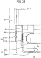
- FIG. 17 is an illustration of a configuration according to a third modification in which the elastic member 50 is in contact with the inner surface of the front cover 20.
- the configuration according to the third modification is the same as the configuration according to the embodiment illustrated, for example, in FIG. 9 except for the heat dissipating section 333 of the heat dissipation sheet 30 and the elastic member 50.
- the description of the same configuration is omitted.
- FIG. 17 illustrates a set of the heat dissipation sheet 30 and the elastic member 50, it is assumed that two sets of heat dissipation sheet 30 (the heat dissipating section 333) and the elastic member 50 are arranged in parallel, corresponding to the image sensors 12A and 12B, respectively.
- the heat dissipation sheet 30 is attached to the support plate 36a of the base 36 via the adhesive layer on the back of the heat dissipating section 333. That is, the heat dissipating section 333 is directly supported by the support plate 36a without the elastic member 50.
- the elastic member 50 is made of material that is elastically deformable and has high thermal conductivity.
- the adhesive layer on the back face of the elastic member 50 is attached to the front face of the heat dissipating section 333, which enables heat to be transferred from the heat dissipating section 33 to the elastic member 50.
- An adhesive layer is not formed on the front face of the elastic member 50, and the front face of the elastic member 50 is exposed to the outside when the front cover 20 is not attached to the rear cover 21.
- the front cover 20 partially illustrated in FIG. 17 is at a position when attached to the rear cover 21.
- the elastic member 50 in FIG. 17 is neither compressed nor deformed, that is, the elastic member 50 is at the first state.
- Q1 denotes the distance between the support plate 36a and the inner surface of the front cover 20
- Q3 denotes the distance between the support plate 36a and the front face of the elastic member 50 (the sum of the thicknesses of the elastic member 50 and the heat dissipating section 333)
- the relation that Q1 is smaller than Q3 Q1 ⁇ Q3
- the elastic member 50 at the first state projects forward (to the front as indicated by arrow in FIG. 9 ) beyond the inner surface of the front cover 20 attached to the rear cover 21.
- This configuration enables the heat to be transferred from the heat dissipating section 333 to the front cover 20 through the elastic member 50, which thus enables the heat generated by the image sensor 12 to be dissipated to the exterior component, such as the front cover 20 made of metal, over a wide area using the heat dissipation sheet 30 and the elastic member 50.
- the back face of the heat dissipating section 333 is in contact with the support plate 36a of the base 36.
- This arrangement also enables heat to be transferred from the heat dissipating section 333 to the front plate 27a of the transverse plate 27 through the support plate 36a. That is, as in the first modification illustrated in FIGs. 10 and 11 , a heat dissipation route through the metal frame (the side plates 25 and 26, and the transverse plate 27) is also formed, which increases heat dissipation property.
- the elastic member 50 is merely compressed against the front cover 20 without any attachment by, for example, adhesive.
- the heat dissipation sheet 30 and the elastic member 50 might not be damaged when the front cover 20 is removed from the imaging apparatus 10.
- the configuration according to the third modification provides a simple and easy-maintenance structure to enable the heat generated by the image sensor 12 to be effectively dissipated to the exterior component, such as the front cover 20, same as in the above-described embodiment, the first and second modifications.
- a description is given of dissipation of heat from a heat source other than the image sensors 12A and 12B in the imaging apparatus 10, referring to FIGs. 18 to 26 . In FIGs.
- the configuration according to the first modification (provided with the heat dissipating section 133 in each of the heat dissipation sheets 30A and 30B) is applied to the dissipation of heat from the image sensors 12A and 12B. That is, the exterior contact 133a of the heat dissipating section 133 contacts the inner surface of the front cover 20, and the frame contact 133b is disposed between the support plate 36a and the front plate 27a.
- a first board 60 and a second board 61 are incorporated in the imaging apparatus 10.
- the battery 23 is disposed (supported) on the front side of the bottom plate 27c of the transverse plate 27.
- a thermal diffusion body 62 is disposed in contact with the back face of the bottom plate 27c, and the first board 60 is disposed in contact with the back face of the thermal diffusion body 62.
- a thermal diffusion body 63 is disposed in contact with the back face of the first board 60, and the second board 61 is disposed in contact with the back face of the thermal diffusion body 63.
- the first board 60 is an electronic circuit board provided with, for example, a controller configured to control the imaging apparatus 10 in a centralized manner and an image processing unit to process an image captured by the optical unit 11.
- the second board 61 is an electronic circuit board that serves to input operation signals (for example, the shutter button 22, the power button 28, and operation button 29) of various kinds of operation parts, input/output signals through the external connector 16, and control displaying of the display unit 24.
- the rear cover 21 is provided with a plurality of bosses 21d each projecting forward.
- the plurality of bosses 21d is disposed at different position along the right-right-to-left direction, each boss 21d has a screw hole inside.
- the first board 60 is disposed on the front-end face of each boss 21d, and the resin spacer 65 is disposed on the front face of the first board 60.
- a bottom plate 27c (a plate) of the transverse plate 27 is disposed on the front face of the spacer 65.
- Through-holes communicable with the screw holes of the bosses 21d are formed in the bottom plate 27c, the spacer 65, and the first board 60, respectively.
- a shaft of each screw 71 is inserted into a through-hole from the front side.
- An external screw formed on the shaft of the screw 71 is screwed into a screw hole of the boss 21d.
- the rear cover 21 further includes a boss 21e at a position above the boss 21d.
- a screw hole is formed inside the boss 21e.
- the side plate 26 has a bending section 26b to bend inwardly (to the right) of the imaging apparatus 10.
- the bending section 26b is superimposed on the front-end face of the boss 21e, and the back face of the first board 60 is superimposed on the front face of the bending section 26b.
- Through-holes communicable with the screw holes of the bosses 21e are formed in the first board 60 and the bending section 26b, respectively.
- a shaft of each screw 72 is inserted into each through-hole from the front side.
- An external screw formed on the shaft of the screw 72 is screwed into a screw hole of the boss 21e.
- the screw 72 is tightened with a certain torque with the head of the screw 72 in contact with the first board 60, the first board 60 and the bending section 26b are held (disposed) between the head of the screw 72 and the boss 21e.
- the second board 61 is disposed at a position at the back of the first board 60, and is supported by the inner surface of the rear cover 21.
- the thermal diffusion body 63 is held between the first board 60 and the second board 61.
- the thermal diffusion body 63 is in close contact with both the first board 60 and the second board 61.
- the thermal diffusion body 63 is held between the first board 60 and the bottom plate 27c of the transverse plate 27.
- the thermal diffusion body 62 is in close contact with both the bottom plate 27c and the first board 60.
- Both the first board 60 and the second board 61 serve as heat sources (a heating body) that generate heat during processing of the mounted circuit and the like, and in particular, the amount of heat generated by the first board 60 is large.
- the battery 23 also serves as a heat source (a heating body).
- the heat generated by the first board 60 is absorbed and diffused by the thermal diffusion bodies 62 and 63, which are disposed at the front and back of the first board 60.
- the heat generated by the second board 61 is absorbed and diffused by the thermal diffusion body 63 in contact with the front side of the second board 61.
- the bottom plate 27c of the transverse plate 27 is in contact with the front face of the thermal diffusion body 62, and the heat absorbed by the thermal diffusion body 62 is transmitted from the bottom plate 27c to the transverse plate 27. Further, the heat generated by the battery 23 is also transmitted from the bottom plate 27c to the transverse plate 27.
- the transverse plate 27 is attached to the fastening sections 25a and 26a of the side plates 25 and 26 with the screws 70, and the heat received by the bottom plate 27c is transmitted to the side plates 25 and 26.
- the side plates 25 and 26 are attached to the rear cover 21 with the screws 73 and 74, and are attached to the front cover 20 as well to allow for the heat transfer.
- the frame contact 133b of the heat dissipating section 133 is in contact with the front plate 27a of the transverse plate 27, and the heat received by the transverse plate 27 is transferred to the front cover 20 through the heat dissipating section 133 of the heat dissipation sheets 30A and 30B.
- This configuration forms a heat-transfer path from the first board 60, the second board 61, and the battery 23 to the thermal diffusion bodies 62 and 63, the transverse plate 27, the side plates 25 and 26, and the heat dissipation sheets 30A and 30B, and to the front cover 20 and the rear cover 21.
- the rear face of the first board 60 is in contact with the front-end face of the boss 21d, and the heat of the first board 60 is directly transferred to the rear cover 21 through the boss 21d.
- the head of the screw 71 is in contact with the bottom plate 27c of the transverse plate 27, and the heat can be transferred to the transverse plate 27 through the screw 71.
- the back face of the first board 60 is in contact with the bending section 26b of the side plate 26, and the front face of the first board 60 is in contact with the head of the screw 72.
- the heat of the first board 60 can be transferred to the bosses 21e and the like of the rear cover 21 through the screws 72.
- the imaging apparatus 10 enables heat generated by the heat sources, such as the first board 60, the second board 61, and the battery 23, in addition to the image sensors 12A and 12B, to be effectively dissipated to the exterior components such as the front cover 20 and the rear cover 21.
- such a configuration provides the first board 60, which generates a great amount of heat, an advantageous heat-dissipation property by forming a plurality of heat-transfer paths.
- the heat of the first board 60 can be dissipated through, for example, the heat-transfer path to the bottom plate 27c of the transverse plate 27 through the thermal diffusion body 62 and the screws 71, the heat-transfer path to the boss 21d of the rear cover 21, the heat-transfer path to the bending section 26b of the side plate 26, and the heat-transfer path to the boss 21e of the rear cover 21 through the screws 71.
- the battery 23 is accommodated in a space (the front side of the bottom plate 27c) formed by the transverse plate 27, and the bottom plate 27c is disposed between the battery 23 and the first board 60 along the front-to-back direction.
- two heat sources (the first board 60 and the battery 23), whose generated heat is to be dissipated to the transverse plate 27, are arranged compactly with the bottom plate 27c (a heat-dissipation target) disposed between the first board 60 and the battery 23.
- the transverse plate 27 constituting the internal frame of the imaging apparatus 10 is capable of receiving the heat generated by the image sensors 12A and 12B using the heat dissipation sheets 30A and 30B. Further, the heat generated by the boards 60 and 61, and the battery 23 can also be transferred to the transverse plate 27. That is, the image sensors 12A and 12B, the first board 60, the second board 61, and the battery 23 share the internal frame (the transverse plate 27) as the heat-transfer path.
- This configuration provides a heat-transfer structure for a plurality of heat sources within a limited internal space of the imaging apparatus 10.
- the frame contacts 133b of the heat dissipation sheets 30A and 30B are in contact with the front plates 27a of the transverse plate 27.
- the heat dissipation sheets 30A and 30B are in direct contact with the transverse plate 27, an effective heat transfer can be performed in any of cases in which the heat generated by the image sensors 12A and 12B is transferred to the transverse plate 27 and in which the heat is transferred from other heat sources (the first board 60, the second board 61, and the battery 23) to the heat dissipation sheets 30A and 30B through the transverse plate 27.
- any components that is capable of transferring heat to the heat dissipation sheets 30A and 30B other than the frame contact 133b may be used to contact the front plate 27a of the transverse plate 27.
- the configurations illustrated in FIGs. 5 to 9 also enables heat to be dissipated from the heat dissipating section 33 to the front plate 27a using the support plate 36a of the base 36 and the elastic member 35 if the elastic member 35 is made of material having high thermal conductivity.
- the embodiments and modifications have been demonstrated described above, the present disclosure is not limited to such specific embodiments and modifications, and other embodiments and modifications may be used without departing from the spirit and scope of the present disclosure.
- the embodiments and modifications of the present disclosure are particularly effective in the imaging apparatus provided with a spherical imaging system according to the above-described embodiments, and more effective in the configuration in which a plurality of image sensors are arranged with the board surfaces (BS) facing each other.
- the embodiments and modifications of the present disclosure are also applicable in imaging apparatuses provided with an imaging system other than a spherical imaging system.
- the imaging apparatus 10 As the imaging apparatus 10 according to the above-described embodiments is thin in the front-to-back direction, a sufficient area for the compressive contact can be obtained by compressing the heat dissipating section 33, 133, and 233 of the heat dissipation sheets 30A and 30B and the elastic member 50 against the front cover 20 and the rear cover 21 of the exterior components.
- the configuration that compresses the heat dissipating sections 33, 133, 233, and the elastic member 50 against the front cover 20 can improve maintainability and workability because the front cover 20 is attached to the rear cover 21 in the last to assemble the imaging apparatus 10.
- the heat dissipating section and a heat conductive elastic member may be compressed against the exterior components that cover the up and down sides or the right and left sides of the imaging apparatus, instead of the front and rear covers.
Landscapes
- Engineering & Computer Science (AREA)
- Physics & Mathematics (AREA)
- Multimedia (AREA)
- Signal Processing (AREA)
- General Physics & Mathematics (AREA)
- Aviation & Aerospace Engineering (AREA)
- Microelectronics & Electronic Packaging (AREA)
- Thermal Sciences (AREA)
- Optics & Photonics (AREA)
- Electromagnetism (AREA)
- Studio Devices (AREA)
- Camera Bodies And Camera Details Or Accessories (AREA)
- Cooling Or The Like Of Electrical Apparatus (AREA)
Applications Claiming Priority (2)
| Application Number | Priority Date | Filing Date | Title |
|---|---|---|---|
| JP2018138084 | 2018-07-24 | ||
| JP2019029669A JP7151541B2 (ja) | 2018-07-24 | 2019-02-21 | 撮像装置 |
Publications (3)
| Publication Number | Publication Date |
|---|---|
| EP3599493A2 true EP3599493A2 (fr) | 2020-01-29 |
| EP3599493A3 EP3599493A3 (fr) | 2020-05-06 |
| EP3599493B1 EP3599493B1 (fr) | 2023-01-18 |
Family
ID=67438470
Family Applications (1)
| Application Number | Title | Priority Date | Filing Date |
|---|---|---|---|
| EP19187690.3A Active EP3599493B1 (fr) | 2018-07-24 | 2019-07-23 | Appareil d'imagerie |
Country Status (3)
| Country | Link |
|---|---|
| US (1) | US11013148B2 (fr) |
| EP (1) | EP3599493B1 (fr) |
| CN (1) | CN110784627B (fr) |
Cited By (1)
| Publication number | Priority date | Publication date | Assignee | Title |
|---|---|---|---|---|
| US20240214655A1 (en) * | 2022-12-26 | 2024-06-27 | Panasonic Intellectual Property Management Co., Ltd. | Imaging device |
Families Citing this family (7)
| Publication number | Priority date | Publication date | Assignee | Title |
|---|---|---|---|---|
| US10917544B2 (en) * | 2019-04-30 | 2021-02-09 | Gopro, Inc. | Heat transfer between integrated sensor-lens assemblies in an image capture device |
| US12078694B2 (en) | 2019-07-30 | 2024-09-03 | Google Llc | Sensor-based tamper detection for mounted electronic devices |
| US11852957B2 (en) | 2020-09-22 | 2023-12-26 | Google Llc | Thermal-control system for a security camera and associated security camera |
| US20230229059A1 (en) * | 2022-01-14 | 2023-07-20 | Aac Optics (Suzhou) Co., Ltd. | Autofocus device based on movable sensor driven by sma wire |
| US20240393665A1 (en) * | 2023-05-22 | 2024-11-28 | Gopro, Inc. | Heat conductor assembly |
| US20240414421A1 (en) * | 2023-06-09 | 2024-12-12 | Gopro, Inc. | Low profile image capture device with a dual heat exchanger and connection mechanism |
| JP2025069807A (ja) * | 2023-10-18 | 2025-05-01 | パナソニックIpマネジメント株式会社 | 撮像装置 |
Citations (2)
| Publication number | Priority date | Publication date | Assignee | Title |
|---|---|---|---|---|
| JPS6218469B2 (fr) | 1981-08-07 | 1987-04-23 | Tore Eng Co Ltd | |
| JP2015023343A (ja) | 2013-07-17 | 2015-02-02 | キヤノン株式会社 | 撮像装置 |
Family Cites Families (34)
| Publication number | Priority date | Publication date | Assignee | Title |
|---|---|---|---|---|
| JP2006319720A (ja) * | 2005-05-13 | 2006-11-24 | Matsushita Electric Ind Co Ltd | 撮像素子駆動装置およびそれを用いた撮影装置 |
| JP2008164799A (ja) * | 2006-12-27 | 2008-07-17 | Sony Corp | 電子機器の筐体及びその筐体を備えた電子機器 |
| JP5291892B2 (ja) * | 2007-05-01 | 2013-09-18 | オリンパスイメージング株式会社 | 撮像素子モジュール、撮像素子モジュールを用いたレンズユニット及び携帯用電子機器 |
| US7933515B2 (en) * | 2008-09-11 | 2011-04-26 | Panasonic Corporation | Camera body and imaging device equipped with same |
| JP5365470B2 (ja) | 2008-11-26 | 2013-12-11 | 株式会社リコー | カメラボディ、撮像ユニット、撮像システム、その撮像ユニットのカメラボディに対する着脱方法、その撮像ユニットのカメラボディに対する装着方法、その撮像ユニットのカメラボディに対する抜き取り方法 |
| EP2399164B1 (fr) | 2009-02-19 | 2018-06-27 | Ricoh Company, Ltd. | Boîtier d'appareil photo, unité d'imagerie montée / démontée sur / du boîtier d'appareil photo et appareil d'imagerie |
| JP5165110B2 (ja) * | 2009-06-26 | 2013-03-21 | パナソニック株式会社 | 撮像装置 |
| JP5445038B2 (ja) | 2009-09-14 | 2014-03-19 | 株式会社リコー | カメラボディ及びこのカメラボディに着脱される撮像ユニット及び撮像装置 |
| JP5413133B2 (ja) | 2009-11-05 | 2014-02-12 | 株式会社リコー | カメラボディ及びこのカメラボディに着脱される撮像ユニット及び撮像装置 |
| JP5454089B2 (ja) | 2009-11-09 | 2014-03-26 | 株式会社リコー | カメラボディおよび撮像装置 |
| JP5565117B2 (ja) * | 2010-06-07 | 2014-08-06 | 株式会社リコー | 撮像装置 |
| JP5566198B2 (ja) * | 2010-06-16 | 2014-08-06 | キヤノン株式会社 | 電子機器 |
| JP2012042562A (ja) * | 2010-08-16 | 2012-03-01 | Canon Inc | 撮像装置 |
| JP2012058405A (ja) | 2010-09-07 | 2012-03-22 | Olympus Imaging Corp | 手振れ補正ユニット |
| JPWO2012077251A1 (ja) * | 2010-12-06 | 2014-05-19 | パナソニック株式会社 | 撮像装置 |
| JP5813351B2 (ja) | 2011-04-01 | 2015-11-17 | 株式会社日立国際電気 | 撮像装置及び撮像装置の製造方法 |
| CN102098433B (zh) | 2011-04-02 | 2012-11-07 | 天津天地伟业数码科技有限公司 | 高清摄像机的散热结构 |
| JP5948825B2 (ja) | 2011-12-01 | 2016-07-06 | 株式会社リコー | 開閉蓋装置、電子機器 |
| JP2014081504A (ja) | 2012-10-17 | 2014-05-08 | Ricoh Co Ltd | 撮像ユニットおよび電子機器 |
| JP6080510B2 (ja) | 2012-11-09 | 2017-02-15 | キヤノン株式会社 | 放熱部品、撮像装置及び電子機器 |
| JP6315229B2 (ja) * | 2013-06-27 | 2018-04-25 | 株式会社リコー | 放熱部品、電子機器 |
| JP2016219599A (ja) | 2015-05-20 | 2016-12-22 | 株式会社リコー | 電子機器および熱拡散体 |
| WO2017073078A1 (fr) | 2015-10-30 | 2017-05-04 | キヤノン株式会社 | Dispositif électronique |
| DE112016004957T5 (de) | 2015-10-30 | 2018-07-19 | Canon Kabushiki Kaisha | Elektronische vorrichtung |
| JP6666035B2 (ja) * | 2015-12-25 | 2020-03-13 | キヤノン株式会社 | 撮像装置 |
| JP6645245B2 (ja) | 2016-02-19 | 2020-02-14 | 株式会社ザクティ | 全天球撮影システム |
| CN205596496U (zh) * | 2016-03-15 | 2016-09-21 | 深圳Tcl数字技术有限公司 | 散热装置及电视机 |
| CN105915769A (zh) * | 2016-03-30 | 2016-08-31 | 努比亚技术有限公司 | 一种摄像头散热装置及移动终端 |
| CN205670799U (zh) | 2016-06-15 | 2016-11-02 | 北京旷视科技有限公司 | 一种散热装置以及具有其的摄像机 |
| US10133158B2 (en) * | 2016-10-17 | 2018-11-20 | Panasonic Intellectual Property Management Co., Ltd. | Imaging device |
| CN106572621B (zh) | 2016-11-10 | 2018-12-21 | 广东高标电子科技有限公司 | 控制器以及具有该控制器的电动车 |
| CN106686963B (zh) * | 2016-12-20 | 2019-05-24 | Oppo广东移动通信有限公司 | 功能器件和终端设备 |
| JP6919242B2 (ja) | 2017-03-16 | 2021-08-18 | 株式会社リコー | 音声取得装置 |
| CN207573441U (zh) * | 2017-12-13 | 2018-07-03 | 广东拉斐尔科技有限公司 | 一种带usb数据线的手机壳 |
-
2019
- 2019-07-15 US US16/510,980 patent/US11013148B2/en active Active
- 2019-07-23 EP EP19187690.3A patent/EP3599493B1/fr active Active
- 2019-07-24 CN CN201910671124.5A patent/CN110784627B/zh active Active
Patent Citations (2)
| Publication number | Priority date | Publication date | Assignee | Title |
|---|---|---|---|---|
| JPS6218469B2 (fr) | 1981-08-07 | 1987-04-23 | Tore Eng Co Ltd | |
| JP2015023343A (ja) | 2013-07-17 | 2015-02-02 | キヤノン株式会社 | 撮像装置 |
Cited By (2)
| Publication number | Priority date | Publication date | Assignee | Title |
|---|---|---|---|---|
| US20240214655A1 (en) * | 2022-12-26 | 2024-06-27 | Panasonic Intellectual Property Management Co., Ltd. | Imaging device |
| US12382154B2 (en) * | 2022-12-26 | 2025-08-05 | Panasonic Intellectual Property Management Co., Ltd. | Imaging device |
Also Published As
| Publication number | Publication date |
|---|---|
| US20200037471A1 (en) | 2020-01-30 |
| EP3599493A3 (fr) | 2020-05-06 |
| CN110784627A (zh) | 2020-02-11 |
| EP3599493B1 (fr) | 2023-01-18 |
| US11013148B2 (en) | 2021-05-18 |
| CN110784627B (zh) | 2021-07-16 |
Similar Documents
| Publication | Publication Date | Title |
|---|---|---|
| EP3599493B1 (fr) | Appareil d'imagerie | |
| JP7151541B2 (ja) | 撮像装置 | |
| JP7191915B2 (ja) | 撮像装置 | |
| US20160070088A1 (en) | Imaging apparatus having bending optical element | |
| JP5117967B2 (ja) | 電子機器および撮像機能付き電子機器 | |
| CN106534655A (zh) | 摄像头模组及移动终端 | |
| JP4872091B2 (ja) | 撮像装置 | |
| JP6732438B2 (ja) | 撮像装置 | |
| CN113885272B (zh) | 驱动装置、摄像模组及电子设备 | |
| CN102243416A (zh) | 包括作为发热源的电子部件的电子设备 | |
| JP6080510B2 (ja) | 放熱部品、撮像装置及び電子機器 | |
| JP2012032704A (ja) | 撮像装置 | |
| JP2010074722A (ja) | 撮像素子の放熱構造及びカメラ | |
| JPWO2013150621A1 (ja) | 撮像装置 | |
| WO2013014717A1 (fr) | Dispositif de formation d'images | |
| JP5460178B2 (ja) | 撮像装置 | |
| JP5925053B2 (ja) | 撮像装置 | |
| CN114745477A (zh) | 摄像模组及电子设备 | |
| JP2001326840A (ja) | 撮像装置 | |
| JP2015072960A (ja) | 電子機器 | |
| JPH11341321A (ja) | 撮像装置 | |
| JP2007134811A (ja) | 撮像装置 | |
| JP2011138912A (ja) | 電子機器 | |
| JP2014039163A (ja) | 電子機器 | |
| CN107147835A (zh) | 电子装置 |
Legal Events
| Date | Code | Title | Description |
|---|---|---|---|
| PUAI | Public reference made under article 153(3) epc to a published international application that has entered the european phase |
Free format text: ORIGINAL CODE: 0009012 |
|
| STAA | Information on the status of an ep patent application or granted ep patent |
Free format text: STATUS: REQUEST FOR EXAMINATION WAS MADE |
|
| 17P | Request for examination filed |
Effective date: 20190723 |
|
| AK | Designated contracting states |
Kind code of ref document: A2 Designated state(s): AL AT BE BG CH CY CZ DE DK EE ES FI FR GB GR HR HU IE IS IT LI LT LU LV MC MK MT NL NO PL PT RO RS SE SI SK SM TR |
|
| AX | Request for extension of the european patent |
Extension state: BA ME |
|
| PUAL | Search report despatched |
Free format text: ORIGINAL CODE: 0009013 |
|
| AK | Designated contracting states |
Kind code of ref document: A3 Designated state(s): AL AT BE BG CH CY CZ DE DK EE ES FI FR GB GR HR HU IE IS IT LI LT LU LV MC MK MT NL NO PL PT RO RS SE SI SK SM TR |
|
| AX | Request for extension of the european patent |
Extension state: BA ME |
|
| RIC1 | Information provided on ipc code assigned before grant |
Ipc: G03B 37/04 20060101ALI20200402BHEP Ipc: H04N 5/225 20060101ALI20200402BHEP Ipc: G02B 7/00 20060101AFI20200402BHEP Ipc: G03B 17/02 20060101ALI20200402BHEP Ipc: G03B 17/55 20060101ALI20200402BHEP |
|
| REG | Reference to a national code |
Ref country code: DE Ref legal event code: R079 Ref document number: 602019024482 Country of ref document: DE Free format text: PREVIOUS MAIN CLASS: G02B0007000000 Ipc: G02B0013060000 |
|
| RIC1 | Information provided on ipc code assigned before grant |
Ipc: H04N 5/225 20060101ALI20220719BHEP Ipc: G03B 37/04 20060101ALI20220719BHEP Ipc: G03B 17/02 20060101ALI20220719BHEP Ipc: G03B 17/55 20060101ALI20220719BHEP Ipc: G02B 7/00 20060101ALI20220719BHEP Ipc: G02B 13/06 20060101AFI20220719BHEP |
|
| GRAP | Despatch of communication of intention to grant a patent |
Free format text: ORIGINAL CODE: EPIDOSNIGR1 |
|
| STAA | Information on the status of an ep patent application or granted ep patent |
Free format text: STATUS: GRANT OF PATENT IS INTENDED |
|
| INTG | Intention to grant announced |
Effective date: 20220830 |
|
| RAP3 | Party data changed (applicant data changed or rights of an application transferred) |
Owner name: RICOH COMPANY, LTD. |
|
| RIN1 | Information on inventor provided before grant (corrected) |
Inventor name: KAGA, RYOTA |
|
| GRAS | Grant fee paid |
Free format text: ORIGINAL CODE: EPIDOSNIGR3 |
|
| GRAA | (expected) grant |
Free format text: ORIGINAL CODE: 0009210 |
|
| STAA | Information on the status of an ep patent application or granted ep patent |
Free format text: STATUS: THE PATENT HAS BEEN GRANTED |
|
| AK | Designated contracting states |
Kind code of ref document: B1 Designated state(s): AL AT BE BG CH CY CZ DE DK EE ES FI FR GB GR HR HU IE IS IT LI LT LU LV MC MK MT NL NO PL PT RO RS SE SI SK SM TR |
|
| REG | Reference to a national code |
Ref country code: GB Ref legal event code: FG4D |
|
| REG | Reference to a national code |
Ref country code: CH Ref legal event code: EP |
|
| REG | Reference to a national code |
Ref country code: DE Ref legal event code: R096 Ref document number: 602019024482 Country of ref document: DE |
|
| REG | Reference to a national code |
Ref country code: AT Ref legal event code: REF Ref document number: 1545020 Country of ref document: AT Kind code of ref document: T Effective date: 20230215 Ref country code: IE Ref legal event code: FG4D |
|
| REG | Reference to a national code |
Ref country code: LT Ref legal event code: MG9D |
|
| REG | Reference to a national code |
Ref country code: NL Ref legal event code: MP Effective date: 20230118 |
|
| REG | Reference to a national code |
Ref country code: AT Ref legal event code: MK05 Ref document number: 1545020 Country of ref document: AT Kind code of ref document: T Effective date: 20230118 |
|
| PG25 | Lapsed in a contracting state [announced via postgrant information from national office to epo] |
Ref country code: NL Free format text: LAPSE BECAUSE OF FAILURE TO SUBMIT A TRANSLATION OF THE DESCRIPTION OR TO PAY THE FEE WITHIN THE PRESCRIBED TIME-LIMIT Effective date: 20230118 |
|
| PG25 | Lapsed in a contracting state [announced via postgrant information from national office to epo] |
Ref country code: RS Free format text: LAPSE BECAUSE OF FAILURE TO SUBMIT A TRANSLATION OF THE DESCRIPTION OR TO PAY THE FEE WITHIN THE PRESCRIBED TIME-LIMIT Effective date: 20230118 Ref country code: PT Free format text: LAPSE BECAUSE OF FAILURE TO SUBMIT A TRANSLATION OF THE DESCRIPTION OR TO PAY THE FEE WITHIN THE PRESCRIBED TIME-LIMIT Effective date: 20230518 Ref country code: NO Free format text: LAPSE BECAUSE OF FAILURE TO SUBMIT A TRANSLATION OF THE DESCRIPTION OR TO PAY THE FEE WITHIN THE PRESCRIBED TIME-LIMIT Effective date: 20230418 Ref country code: LV Free format text: LAPSE BECAUSE OF FAILURE TO SUBMIT A TRANSLATION OF THE DESCRIPTION OR TO PAY THE FEE WITHIN THE PRESCRIBED TIME-LIMIT Effective date: 20230118 Ref country code: LT Free format text: LAPSE BECAUSE OF FAILURE TO SUBMIT A TRANSLATION OF THE DESCRIPTION OR TO PAY THE FEE WITHIN THE PRESCRIBED TIME-LIMIT Effective date: 20230118 Ref country code: HR Free format text: LAPSE BECAUSE OF FAILURE TO SUBMIT A TRANSLATION OF THE DESCRIPTION OR TO PAY THE FEE WITHIN THE PRESCRIBED TIME-LIMIT Effective date: 20230118 Ref country code: ES Free format text: LAPSE BECAUSE OF FAILURE TO SUBMIT A TRANSLATION OF THE DESCRIPTION OR TO PAY THE FEE WITHIN THE PRESCRIBED TIME-LIMIT Effective date: 20230118 Ref country code: AT Free format text: LAPSE BECAUSE OF FAILURE TO SUBMIT A TRANSLATION OF THE DESCRIPTION OR TO PAY THE FEE WITHIN THE PRESCRIBED TIME-LIMIT Effective date: 20230118 |
|
| P01 | Opt-out of the competence of the unified patent court (upc) registered |
Effective date: 20230714 |
|
| PG25 | Lapsed in a contracting state [announced via postgrant information from national office to epo] |
Ref country code: SE Free format text: LAPSE BECAUSE OF FAILURE TO SUBMIT A TRANSLATION OF THE DESCRIPTION OR TO PAY THE FEE WITHIN THE PRESCRIBED TIME-LIMIT Effective date: 20230118 Ref country code: PL Free format text: LAPSE BECAUSE OF FAILURE TO SUBMIT A TRANSLATION OF THE DESCRIPTION OR TO PAY THE FEE WITHIN THE PRESCRIBED TIME-LIMIT Effective date: 20230118 Ref country code: IS Free format text: LAPSE BECAUSE OF FAILURE TO SUBMIT A TRANSLATION OF THE DESCRIPTION OR TO PAY THE FEE WITHIN THE PRESCRIBED TIME-LIMIT Effective date: 20230518 Ref country code: GR Free format text: LAPSE BECAUSE OF FAILURE TO SUBMIT A TRANSLATION OF THE DESCRIPTION OR TO PAY THE FEE WITHIN THE PRESCRIBED TIME-LIMIT Effective date: 20230419 Ref country code: FI Free format text: LAPSE BECAUSE OF FAILURE TO SUBMIT A TRANSLATION OF THE DESCRIPTION OR TO PAY THE FEE WITHIN THE PRESCRIBED TIME-LIMIT Effective date: 20230118 |
|
| REG | Reference to a national code |
Ref country code: DE Ref legal event code: R097 Ref document number: 602019024482 Country of ref document: DE |
|
| PG25 | Lapsed in a contracting state [announced via postgrant information from national office to epo] |
Ref country code: SM Free format text: LAPSE BECAUSE OF FAILURE TO SUBMIT A TRANSLATION OF THE DESCRIPTION OR TO PAY THE FEE WITHIN THE PRESCRIBED TIME-LIMIT Effective date: 20230118 Ref country code: RO Free format text: LAPSE BECAUSE OF FAILURE TO SUBMIT A TRANSLATION OF THE DESCRIPTION OR TO PAY THE FEE WITHIN THE PRESCRIBED TIME-LIMIT Effective date: 20230118 Ref country code: EE Free format text: LAPSE BECAUSE OF FAILURE TO SUBMIT A TRANSLATION OF THE DESCRIPTION OR TO PAY THE FEE WITHIN THE PRESCRIBED TIME-LIMIT Effective date: 20230118 Ref country code: DK Free format text: LAPSE BECAUSE OF FAILURE TO SUBMIT A TRANSLATION OF THE DESCRIPTION OR TO PAY THE FEE WITHIN THE PRESCRIBED TIME-LIMIT Effective date: 20230118 Ref country code: CZ Free format text: LAPSE BECAUSE OF FAILURE TO SUBMIT A TRANSLATION OF THE DESCRIPTION OR TO PAY THE FEE WITHIN THE PRESCRIBED TIME-LIMIT Effective date: 20230118 |
|
| PLBE | No opposition filed within time limit |
Free format text: ORIGINAL CODE: 0009261 |
|
| STAA | Information on the status of an ep patent application or granted ep patent |
Free format text: STATUS: NO OPPOSITION FILED WITHIN TIME LIMIT |
|
| PG25 | Lapsed in a contracting state [announced via postgrant information from national office to epo] |
Ref country code: SK Free format text: LAPSE BECAUSE OF FAILURE TO SUBMIT A TRANSLATION OF THE DESCRIPTION OR TO PAY THE FEE WITHIN THE PRESCRIBED TIME-LIMIT Effective date: 20230118 |
|
| 26N | No opposition filed |
Effective date: 20231019 |
|
| PG25 | Lapsed in a contracting state [announced via postgrant information from national office to epo] |
Ref country code: SI Free format text: LAPSE BECAUSE OF FAILURE TO SUBMIT A TRANSLATION OF THE DESCRIPTION OR TO PAY THE FEE WITHIN THE PRESCRIBED TIME-LIMIT Effective date: 20230118 |
|
| PG25 | Lapsed in a contracting state [announced via postgrant information from national office to epo] |
Ref country code: MC Free format text: LAPSE BECAUSE OF FAILURE TO SUBMIT A TRANSLATION OF THE DESCRIPTION OR TO PAY THE FEE WITHIN THE PRESCRIBED TIME-LIMIT Effective date: 20230118 |
|
| PG25 | Lapsed in a contracting state [announced via postgrant information from national office to epo] |
Ref country code: MC Free format text: LAPSE BECAUSE OF FAILURE TO SUBMIT A TRANSLATION OF THE DESCRIPTION OR TO PAY THE FEE WITHIN THE PRESCRIBED TIME-LIMIT Effective date: 20230118 |
|
| REG | Reference to a national code |
Ref country code: CH Ref legal event code: PL |
|
| REG | Reference to a national code |
Ref country code: BE Ref legal event code: MM Effective date: 20230731 |
|
| PG25 | Lapsed in a contracting state [announced via postgrant information from national office to epo] |
Ref country code: LU Free format text: LAPSE BECAUSE OF NON-PAYMENT OF DUE FEES Effective date: 20230723 |
|
| PG25 | Lapsed in a contracting state [announced via postgrant information from national office to epo] |
Ref country code: LU Free format text: LAPSE BECAUSE OF NON-PAYMENT OF DUE FEES Effective date: 20230723 |
|
| REG | Reference to a national code |
Ref country code: IE Ref legal event code: MM4A |
|
| PG25 | Lapsed in a contracting state [announced via postgrant information from national office to epo] |
Ref country code: CH Free format text: LAPSE BECAUSE OF NON-PAYMENT OF DUE FEES Effective date: 20230731 |
|
| PG25 | Lapsed in a contracting state [announced via postgrant information from national office to epo] |
Ref country code: IT Free format text: LAPSE BECAUSE OF FAILURE TO SUBMIT A TRANSLATION OF THE DESCRIPTION OR TO PAY THE FEE WITHIN THE PRESCRIBED TIME-LIMIT Effective date: 20230118 Ref country code: BE Free format text: LAPSE BECAUSE OF NON-PAYMENT OF DUE FEES Effective date: 20230731 |
|
| PG25 | Lapsed in a contracting state [announced via postgrant information from national office to epo] |
Ref country code: IE Free format text: LAPSE BECAUSE OF NON-PAYMENT OF DUE FEES Effective date: 20230723 |
|
| PG25 | Lapsed in a contracting state [announced via postgrant information from national office to epo] |
Ref country code: IE Free format text: LAPSE BECAUSE OF NON-PAYMENT OF DUE FEES Effective date: 20230723 |
|
| PG25 | Lapsed in a contracting state [announced via postgrant information from national office to epo] |
Ref country code: BG Free format text: LAPSE BECAUSE OF FAILURE TO SUBMIT A TRANSLATION OF THE DESCRIPTION OR TO PAY THE FEE WITHIN THE PRESCRIBED TIME-LIMIT Effective date: 20230118 |
|
| PG25 | Lapsed in a contracting state [announced via postgrant information from national office to epo] |
Ref country code: BG Free format text: LAPSE BECAUSE OF FAILURE TO SUBMIT A TRANSLATION OF THE DESCRIPTION OR TO PAY THE FEE WITHIN THE PRESCRIBED TIME-LIMIT Effective date: 20230118 |
|
| PG25 | Lapsed in a contracting state [announced via postgrant information from national office to epo] |
Ref country code: CY Free format text: LAPSE BECAUSE OF FAILURE TO SUBMIT A TRANSLATION OF THE DESCRIPTION OR TO PAY THE FEE WITHIN THE PRESCRIBED TIME-LIMIT; INVALID AB INITIO Effective date: 20190723 |
|
| PG25 | Lapsed in a contracting state [announced via postgrant information from national office to epo] |
Ref country code: HU Free format text: LAPSE BECAUSE OF FAILURE TO SUBMIT A TRANSLATION OF THE DESCRIPTION OR TO PAY THE FEE WITHIN THE PRESCRIBED TIME-LIMIT; INVALID AB INITIO Effective date: 20190723 |
|
| PGFP | Annual fee paid to national office [announced via postgrant information from national office to epo] |
Ref country code: DE Payment date: 20250722 Year of fee payment: 7 |
|
| PGFP | Annual fee paid to national office [announced via postgrant information from national office to epo] |
Ref country code: GB Payment date: 20250722 Year of fee payment: 7 |
|
| PGFP | Annual fee paid to national office [announced via postgrant information from national office to epo] |
Ref country code: FR Payment date: 20250725 Year of fee payment: 7 |
|
| PG25 | Lapsed in a contracting state [announced via postgrant information from national office to epo] |
Ref country code: TR Free format text: LAPSE BECAUSE OF FAILURE TO SUBMIT A TRANSLATION OF THE DESCRIPTION OR TO PAY THE FEE WITHIN THE PRESCRIBED TIME-LIMIT Effective date: 20230118 |