EP3599713A1 - Convertisseur de fréquence à des ressources temporairement déconnectées - Google Patents
Convertisseur de fréquence à des ressources temporairement déconnectées Download PDFInfo
- Publication number
- EP3599713A1 EP3599713A1 EP18185499.3A EP18185499A EP3599713A1 EP 3599713 A1 EP3599713 A1 EP 3599713A1 EP 18185499 A EP18185499 A EP 18185499A EP 3599713 A1 EP3599713 A1 EP 3599713A1
- Authority
- EP
- European Patent Office
- Prior art keywords
- control electronics
- activated
- setpoint
- basic
- frequency converter
- Prior art date
- Legal status (The legal status is an assumption and is not a legal conclusion. Google has not performed a legal analysis and makes no representation as to the accuracy of the status listed.)
- Withdrawn
Links
- 238000000034 method Methods 0.000 claims abstract description 121
- 239000004065 semiconductor Substances 0.000 claims abstract description 29
- 238000011835 investigation Methods 0.000 claims abstract description 18
- 238000011017 operating method Methods 0.000 claims description 25
- 230000004913 activation Effects 0.000 claims description 21
- 230000008569 process Effects 0.000 claims description 18
- 238000007630 basic procedure Methods 0.000 claims description 9
- 238000012545 processing Methods 0.000 claims description 7
- 230000008859 change Effects 0.000 claims description 6
- 238000001514 detection method Methods 0.000 claims description 6
- 230000004044 response Effects 0.000 claims description 3
- 230000008901 benefit Effects 0.000 description 4
- 230000001419 dependent effect Effects 0.000 description 2
- 230000003213 activating effect Effects 0.000 description 1
- 238000013461 design Methods 0.000 description 1
- 238000011161 development Methods 0.000 description 1
- 230000001172 regenerating effect Effects 0.000 description 1
- 239000000779 smoke Substances 0.000 description 1
Images



Classifications
-
- H—ELECTRICITY
- H02—GENERATION; CONVERSION OR DISTRIBUTION OF ELECTRIC POWER
- H02M—APPARATUS FOR CONVERSION BETWEEN AC AND AC, BETWEEN AC AND DC, OR BETWEEN DC AND DC, AND FOR USE WITH MAINS OR SIMILAR POWER SUPPLY SYSTEMS; CONVERSION OF DC OR AC INPUT POWER INTO SURGE OUTPUT POWER; CONTROL OR REGULATION THEREOF
- H02M7/00—Conversion of AC power input into DC power output; Conversion of DC power input into AC power output
- H02M7/42—Conversion of DC power input into AC power output without possibility of reversal
- H02M7/44—Conversion of DC power input into AC power output without possibility of reversal by static converters
- H02M7/48—Conversion of DC power input into AC power output without possibility of reversal by static converters using discharge tubes with control electrode or semiconductor devices with control electrode
- H02M7/53—Conversion of DC power input into AC power output without possibility of reversal by static converters using discharge tubes with control electrode or semiconductor devices with control electrode using devices of a triode or transistor type requiring continuous application of a control signal
- H02M7/537—Conversion of DC power input into AC power output without possibility of reversal by static converters using discharge tubes with control electrode or semiconductor devices with control electrode using devices of a triode or transistor type requiring continuous application of a control signal using semiconductor devices only, e.g. single switched pulse inverters
- H02M7/5387—Conversion of DC power input into AC power output without possibility of reversal by static converters using discharge tubes with control electrode or semiconductor devices with control electrode using devices of a triode or transistor type requiring continuous application of a control signal using semiconductor devices only, e.g. single switched pulse inverters in a bridge configuration
- H02M7/53871—Conversion of DC power input into AC power output without possibility of reversal by static converters using discharge tubes with control electrode or semiconductor devices with control electrode using devices of a triode or transistor type requiring continuous application of a control signal using semiconductor devices only, e.g. single switched pulse inverters in a bridge configuration with automatic control of output voltage or current
- H02M7/53873—Conversion of DC power input into AC power output without possibility of reversal by static converters using discharge tubes with control electrode or semiconductor devices with control electrode using devices of a triode or transistor type requiring continuous application of a control signal using semiconductor devices only, e.g. single switched pulse inverters in a bridge configuration with automatic control of output voltage or current with digital control
-
- H—ELECTRICITY
- H02—GENERATION; CONVERSION OR DISTRIBUTION OF ELECTRIC POWER
- H02P—CONTROL OR REGULATION OF ELECTRIC MOTORS, ELECTRIC GENERATORS OR DYNAMO-ELECTRIC CONVERTERS; CONTROLLING TRANSFORMERS, REACTORS OR CHOKE COILS
- H02P27/00—Arrangements or methods for the control of AC motors characterised by the kind of supply voltage
- H02P27/04—Arrangements or methods for the control of AC motors characterised by the kind of supply voltage using variable-frequency supply voltage, e.g. inverter or converter supply voltage
- H02P27/06—Arrangements or methods for the control of AC motors characterised by the kind of supply voltage using variable-frequency supply voltage, e.g. inverter or converter supply voltage using DC to AC converters or inverters
-
- H—ELECTRICITY
- H02—GENERATION; CONVERSION OR DISTRIBUTION OF ELECTRIC POWER
- H02P—CONTROL OR REGULATION OF ELECTRIC MOTORS, ELECTRIC GENERATORS OR DYNAMO-ELECTRIC CONVERTERS; CONTROLLING TRANSFORMERS, REACTORS OR CHOKE COILS
- H02P6/00—Arrangements for controlling synchronous motors or other dynamo-electric motors using electronic commutation dependent on the rotor position; Electronic commutators therefor
- H02P6/04—Arrangements for controlling or regulating the speed or torque of more than one motor
-
- H—ELECTRICITY
- H02—GENERATION; CONVERSION OR DISTRIBUTION OF ELECTRIC POWER
- H02M—APPARATUS FOR CONVERSION BETWEEN AC AND AC, BETWEEN AC AND DC, OR BETWEEN DC AND DC, AND FOR USE WITH MAINS OR SIMILAR POWER SUPPLY SYSTEMS; CONVERSION OF DC OR AC INPUT POWER INTO SURGE OUTPUT POWER; CONTROL OR REGULATION THEREOF
- H02M1/00—Details of apparatus for conversion
- H02M1/0003—Details of control, feedback or regulation circuits
- H02M1/0012—Control circuits using digital or numerical techniques
-
- H—ELECTRICITY
- H02—GENERATION; CONVERSION OR DISTRIBUTION OF ELECTRIC POWER
- H02M—APPARATUS FOR CONVERSION BETWEEN AC AND AC, BETWEEN AC AND DC, OR BETWEEN DC AND DC, AND FOR USE WITH MAINS OR SIMILAR POWER SUPPLY SYSTEMS; CONVERSION OF DC OR AC INPUT POWER INTO SURGE OUTPUT POWER; CONTROL OR REGULATION THEREOF
- H02M7/00—Conversion of AC power input into DC power output; Conversion of DC power input into AC power output
- H02M7/42—Conversion of DC power input into AC power output without possibility of reversal
- H02M7/44—Conversion of DC power input into AC power output without possibility of reversal by static converters
- H02M7/48—Conversion of DC power input into AC power output without possibility of reversal by static converters using discharge tubes with control electrode or semiconductor devices with control electrode
- H02M7/493—Conversion of DC power input into AC power output without possibility of reversal by static converters using discharge tubes with control electrode or semiconductor devices with control electrode the static converters being arranged for operation in parallel
Definitions
- the present invention is also based on a control program for control electronics of a frequency converter, the control program comprising machine code which can be processed by the control electronics, the processing of the machine code by the control electronics causing the control electronics to carry out such an operating method.
- the present invention is also based on control electronics of a frequency converter, the control electronics being programmed with such a control program, so that the processing of the machine code by the control electronics causes the control electronics to carry out such an operating method.
- the present invention is also based on a frequency converter, the frequency converter having power semiconductors via which an electrical machine is supplied with electrical energy, the frequency converter having control electronics of this type which controls the power semiconductors.
- Frequency converters are known in many different configurations. Depending on the frequency converter, various functionalities and performance features can be implemented. In the prior art, the functionalities and performance features are implemented within the respective frequency converter - more precisely: within its control electronics. They can be called up and used by the user as required or not called up and thus remain unused. A subsequent expansion or general subsequent adjustment of the functionalities and the performance features depending on the current needs of the user is not possible.
- the object of the present invention is to create possibilities by means of which it is possible to adapt the functional scope of the frequency converter as required at any time, even retrospectively.
- the legitimate interests of the frequency converter manufacturer should also be taken into account.
- an operating method of the type mentioned at the outset is designed in such a way that the control electronics only determine the respective current setpoint and / or the respective control signals according to the determining method if and as long as a permissible scope of use for the determining method is greater than 0. If, on the other hand, the permissible scope of use for the determination process drops to 0, the control electronics stop determining the respective current setpoint and / or the respective control signals in accordance with the determination process. Furthermore, the control electronics at least from time to time reduce the permissible scope of use for the investigation process. The permissible scope of use therefore defines whether the investigation procedure can be used or not. For this reason, the investigation procedure is referred to as an activated investigation procedure.
- the frequency converter provides all the hardware necessary to be able to carry out the enabled detection procedure.
- the need to protect the economic interests of the manufacturer too is taken into account, it is sufficient that the manufacturer only enables certain functionalities and performance features - and thus as a result the determination procedure according to which the control electronics determine the respective current setpoint and the respective control signals - to a limited extent (and for a fee), so that in particular the Development performance and the know-how, which is realized in the functionalities and performance features, are rewarded.
- the operator of the frequency converter is given the opportunity to virtually tailor an individual product specifically for his needs and, moreover, to adapt it individually to changing requirements.
- the permissible scope of use can be defined in any units.
- the only decisive factor is that the scope of use is quantified so that it can be gradually reduced.
- the permitted scope of use can be a period of use that is independent of use, for example a number of days or weeks. It can also be a number of operating hours, i.e. a usage-dependent period of time. It can also be a number of load cycles or clock cycles.
- control electronics can issue a corresponding message whenever the permissible scope of use reaches a lower limit value above 0. This provides the operator of the frequency converter with the option of increasing the permissible scope of use in good time before reaching a permissible usage range of 0. The interest of the operator of the frequency converter is thus safeguarded that he can operate the frequency converter at any time.
- the operating method is designed in such a way that the control electronics, whenever the permitted scope of use reaches the lower limit value, checks whether it is authorized to independently call up an extension of the permitted scope of use. In the affirmative, the control electronics calls the extension of the permitted scope of use from a server via a computer-computer connection. If the answer is no, it issues a corresponding note.
- the control electronics On the one hand, it is possible for the control electronics to completely stop determining the respective current setpoint value and the respective control signals whenever the permitted scope of use for the activated determination method drops to 0. The frequency converter therefore goes out of operation, so to speak. On the other hand, it is possible for the control electronics to continue to determine the respective current setpoint and the respective control signals whenever the permissible scope of use for the activated determination method drops to 0, but to determine the respective current setpoint and / or the respective control signals according to one of the activated ones Investigation procedures determined various basic procedures. The frequency converter therefore goes into a kind of basic operation, so to speak.
- the activation code can be transmitted to the control device in any manner.
- the algorithms and / or parameters required for executing the activated determination method are permanently stored in the control electronics.
- the determination process is activated by the acceptance of an activation code by the control electronics.
- This configuration has the advantage that data need only be transmitted to the control electronics to a small extent. It is even possible for the data to be entered manually using a control panel.
- the determination process it is possible for the determination process to be activated by the control electronics receiving the algorithms and / or parameters required for executing the activated determination process together with an activation code. In this case, a large amount of data traffic is required.
- this embodiment has the advantage that there is less memory requirement on the control electronics side.
- the algorithms and parameters only provide a point of attack for hackers during the period during which they are stored in the control electronics. With permanent storage in the control electronics, however, this point of attack is permanent.
- control electronics causes the control electronics to execute an operating method according to the invention.
- control electronics of a frequency converter with the features of claim 13.
- the control electronics are programmed with a control program according to the invention, so that the processing of the machine code by the control electronics causes the control electronics to execute an operating method according to the invention.
- control electronics which control the semiconductor switches are designed as control electronics according to the invention.
- an industrial technical system 1 is controlled by a control device 2.
- the control device 2 generally controls, among other things, several drives 3.
- the drives 3 each comprise a frequency converter 4 and an electrical machine 5. Subsequently - representative of all frequency converters 4 - is initially in connection with FIG 2 the structure of one of the frequency converters 4 and then the mode of operation of the frequency converter 4 explained in more detail in conjunction with the other FIG.
- the frequency converter 4 has power semiconductors 6.
- the power semiconductors 6 can, for example, as shown in FIG FIG 2 be trained as IGBTs.
- An embodiment as MOSFETs or as thyristors - in particular as GTOs - is also possible.
- the power semiconductors 6 themselves are shown.
- the power semiconductors 6 are additionally connected in parallel with free-wheeling diodes. The freewheeling diodes are not shown.
- the corresponding electrical machine 5 is supplied with electrical energy via the power semiconductors 6.
- the electrical energy is generally obtained from a supply network 7, the electrical energy being rectified by means of a rectifier 8 before being fed to the power semiconductors 6.
- the rectifier 8 can be designed as a regenerative converter or as a simple diode rectifier.
- the frequency converter 4 has control electronics 9.
- the control electronics 9 thus control the power semiconductors 6.
- the control electronics 9 carry control signals corresponding to the power semiconductors 6 C1 to C6 too.
- the control electronics 9 is programmed with a control program 10.
- the control program 10 comprises machine code 11, which can be processed by the control electronics 9.
- the processing of the machine code 11 by the control electronics 9 causes the control electronics 9 to operate the frequency converter 4 according to an operating method which is explained in more detail below in connection with the other FIG.
- control electronics 9 first set a permissible scope of use N to an initial value N0 in a step S1.
- the initial value N0 is greater than 0.
- the permissible scope of use N can be predefined, for example, as a period of use that is independent of use, as a number of operating hours, as a number of load cycles and others.
- step S2 the control electronics 9 checks whether the permissible scope of use N has a value greater than 0. If this is the case, the control electronics 9 go to a step S3.
- step S3 the control electronics 9 accepts a basic setpoint B *.
- the basic setpoint B * describes a desired operating state of the electrical machine 5, for example the position, speed or torque of a conventional rotary electrical machine. In the case of a linear drive, the speed and / or the torque would have to be replaced by the speed and / or the force.
- step S4 the control electronics 9 can also receive an associated basic actual value B of the electrical machine 5, which characterizes the associated actual operating state of the electrical machine 5.
- step S4 is only optional and therefore in FIG 3 only shown with dashed lines.
- step S5 the control electronics 9 determines a current setpoint I * for the electrical machine 5. The determination takes place according to the representation in FIG 5 using the basic setpoint B *. If the basic actual value B is also available, the basic actual value B is usually also used. Step S5 is determined in accordance with a first part f1 of an investigation method. The control electronics 9 then determines the control signals C1 to C6 for the power semiconductors 6 in a step S6. The determination is carried out in accordance with the illustration in FIG FIG 3 using the current setpoint I *. Step S6 is also determined in accordance with a second part f2 of the determination method.
- Both the determination of the current setpoint I * and the determination of the control signals C1 to C6 based thereon are carried out in such a way that the electrical machine 5 is operated as far as possible in accordance with the base setpoint B *.
- the control electronics 9 then control the power semiconductors 6 in accordance with the determined control signals C1 to C6.
- the electrical machine 5 is accordingly supplied with electrical energy.
- step S8 the control electronics 9 checks whether a condition for reducing the permissible scope of use N is fulfilled. If this is the case, the control electronics 9 reduces the permissible scope of use N in a step S9. Otherwise, the step S9 is skipped. In both cases, the control electronics 9 then go back to step S2.
- Steps S2 to S9 are performed by control electronics 9 as shown in FIG FIG 3 repeated with a cycle time T.
- the cycle time T has a value that is in the single-digit millisecond range or less, for example 2 ms, 1 ms, 500 ⁇ s, 250 ⁇ s or 125 ⁇ s.
- control electronics 9 determine the respective current setpoint I * and the respective control signals C1 to C6 in accordance with the determination method defined by parts f1 and f2, if and for as long as the permissible scope of use N is greater than 0. If the permissible scope of use N drops to 0, however, the determination process defined by parts f1 and f2 is not carried out. In this case, the control electronics 9 therefore stop determining the current setpoint I * and the control signals C1 to C6 in accordance with the determination method defined by parts f1 and f2. Instead, the control electronics 9 executes a step S10 in which it takes another measure. The determination according to the determination method defined by parts f1 and f2 is therefore only enabled as long as the permissible scope of use N is greater than 0.
- Step S21 is followed by step S21.
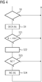
- the control electronics 9 checks whether the permissible scope of use N reaches a lower limit value min.
- the lower limit value min has a value above 0.
- the control electronics 9 go back from step S21 to step S2. Otherwise, the control electronics 9 issues a message in a step S22.
- the message can be transmitted, for example, via a human-machine interface to a user of the system 1, to a higher-level control device - for example the control device 2 - or generally to another computer.
- it is therefore possible to increase the permissible scope of use N for example by specifying a corresponding activation code NC.
- the control electronics 9 therefore checks in a step S23 whether such an activation code NC is specified for it. If this is the case, the control electronics 9 increases the permissible scope of use N accordingly in a step S24.
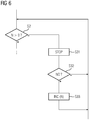
- step S26 the control electronics 9 checks whether it is authorized to independently call up an extension of the permissible scope of use N. If this is the case, the control electronics 9 calls in step S27 - see also FIG 2 - The extension of the permissible scope of use N from a server 13 via a computer-computer connection 12. In particular, it can independently request the NC activation code. Otherwise, if the control electronics 9 is not authorized to independently call up an extension of the permissible scope of use N, the control electronics 9 proceeds to step S22 and from there to steps S23 and S24.
- step S10 There are also various options for the configuration of step S10.
- step S10 is implemented by steps S31 to S33.
- step S31 the control electronics 9 completely stop determining the respective current setpoint I * and the respective control signals C1 to C6. Then, in step S32, it waits for it to be given the activation code NC. If this is the case, the control electronics 9 increases the permissible scope of use N accordingly in a step S33. Steps S32 and S33 thus correspond in content to steps S23 and S24 of FIG 4 and 5 ,
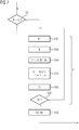
- steps S41 to S45 are present instead of step S31.
- step S41 the control electronics 9 accepts the basic setpoint B *.
- step S42 the control electronics 9 can continue to have an associated basic actual value B of the electrical machine 5 accept. However, step S42 is only optional and therefore in FIG 7 only shown with dashed lines.
- step S43 the control electronics 9 determines the current setpoint I * for the electrical machine 5.
- step S44 the control electronics 9 determines the control signals C1 to C6 for the power semiconductors 6.
- step S45 the control electronics then controls the power semiconductors 6 in accordance with the determined control signals C1 up to C6.
- Steps S41 to S45 therefore correspond to steps S3 to S7 of FIG 3 ,
- step S43 differs from step S5 in that in step S43 the current setpoint I * is not determined in accordance with the first part f1 of the determination method, but rather in accordance with a first part f3 of a basic method.
- step S44 differs from step S6 in that in the context of step S44 the control signals C1 to C6 are not determined in accordance with the second part f2 of the determination method, but rather in accordance with a second part f4 of the basic method.
- the basic method of steps S43 and S44 is a different method than the determination method of steps S5 and S6.
- a current setpoint I * is thus determined, and the control signals C1 to C6 are also determined.
- the current setpoint I * of step S43 has a different value than the current setpoint I * of step S5, given the same input variables.
- the control signals C1 to C6 of step S44 - with the same input variables - have different values than the control signals C1 to C6 of step S6.
- steps S43 and S44 can differ from the determination method S5 and S6 by different properties.
- a cycle time T 'with which the basic method is carried out is greater than that Cycle time T is the time at which the determination process is carried out.
- the cycle time T ' can be twice or four times the cycle time T. If - purely by way of example - the cycle time T is 1 ms, the cycle time T 'could, for example, be 2 ms or 4 ms.
- control electronics 9 it is possible for the control electronics 9 to accept the base actual value B in addition to the base setpoint B * as part of the determination process and to take them into account when determining the respective current setpoint I *, while the control electronics 9 does not accept the base actual value B as part of the base method or not taken into account when determining the current setpoint I *.
- step S4 may exist, but step S42 may not.
- step S5 the first part f1 of the determination method can implement a certain type of controller (for example a PI controller), while in step S43 the first part f3 of the basic method can implement a different type of controller (for example a P controller) ) realized.
- the controller characteristics can also differ, for example with a PI controller, the proportional gains and / or the readjustment times may have different values in the context of the determination method and the basic method.
- the type of controller and / or its controller parameters to be predefined as part of the basic method, while the user can set them within the scope of the determination method. Other variations are also possible.
- the type of basic setpoint B * is different in the context of the basic procedure than in the context of the determination procedure.
- the basic setpoint B * is always a position setpoint as part of the basic process, while the basic setpoint B * is always a speed setpoint or can be set by the user as part of the determination process, whether it is a position setpoint, a speed setpoint or a torque setpoint is.
- a position x of a movable component of the electrical machine 5 is often taken into account, for example a rotary position of the rotor in the case of a rotary electrical machine.
- the position x is detected by means of the position sensor 14 and transmitted to the control electronics 9, while in the basic method it is transmitted by the control electronics 9 is determined without encoder.
- the control electronics 9 can take sensor signals T1, T2 from the surroundings of the frequency converter 4 and / or from the surroundings of the electrical machine 5 into account when determining the current setpoint I * and / or determining the control signals C1 to C6.
- the way in which the basic procedure is taken into account is different from that in the context of the preliminary investigation.
- parameters can be set as to whether the control electronics 9 continue to control the power semiconductors 9 when the limit values T1, T2 are exceeded or whether it adjusts the control.
- the control electronics 9 stop the control of the power semiconductors 9 when the limit values T1, T2 are exceeded.
- the current setpoint I * and / or the control signals C1 to C6 are determined in such a way that a power supplied to the electrical machine 5 is limited to a relatively low value of, for example, 3 kW, while in the context of the determination method, the current setpoint I * and / or the control signals C1 to C6 are determined in such a way that the power supplied to the electrical machine 5 is limited to a higher value of, for example, 10 kW.
- the investigation is activated by not only the activation code NC, but together with the activation code NC also the required algorithms A and / or parameters P are transmitted to the control electronics 9.
- the activation code NC the algorithms A and / or the parameters P are transmitted together to the control electronics 9.
- a control electronics 9 of a frequency converter 4 repeatedly receives a base setpoint B * for the operation of an electrical machine 5 supplied with electrical energy via the frequency converter 4, determines a respective current setpoint I * using the respective base setpoint B * and determines using the respective current setpoint I * respective control signals C1 to C6 for power semiconductors 6 of the frequency converter 4. It controls the power semiconductors 6 according to the determined respective control signals C1 to C6 and thereby supplies the electrical machine 5 with electrical energy in such a way that the electrical machine 5 corresponds as much as possible the basic setpoint B * is operated.
- the control electronics 9 determines the respective current setpoint I * and / or the respective control signals C1 to C6 according to an activated determination method if and as long as a permissible scope of use N for the activated determination method is greater than 0. If, on the other hand, the permissible scope of use N for the activated determination method drops to 0, the control electronics 9 stops determining the respective current setpoint I * and / or the respective control signals C1 to C6 according to the activated determination method. At least from time to time, the control electronics 9 reduce the permissible scope of use N for the activated determination method.
- the present invention has many advantages.
- the variety of types is reduced for the manufacturer of the frequency converter 4 and consequently simplifies logistics in particular.
- the user can continue to request a first functionality, for example, and request a second functionality at a later time - be it in addition to the first functionality or alternatively to the first functionality.
- this is also possible with more than two functionalities.
Landscapes
- Engineering & Computer Science (AREA)
- Power Engineering (AREA)
- Control Of Electric Motors In General (AREA)
- Inverter Devices (AREA)
Priority Applications (5)
| Application Number | Priority Date | Filing Date | Title |
|---|---|---|---|
| EP18185499.3A EP3599713A1 (fr) | 2018-07-25 | 2018-07-25 | Convertisseur de fréquence à des ressources temporairement déconnectées |
| EP19745976.1A EP3759810B1 (fr) | 2018-07-25 | 2019-07-08 | Convertisseur de fréquence à des ressources temporairement déconnectées |
| PCT/EP2019/068207 WO2020020610A1 (fr) | 2018-07-25 | 2019-07-08 | Convertisseur de fréquence avec ressources temporairement déconnectées |
| CN201980049283.XA CN112470394B (zh) | 2018-07-25 | 2019-07-08 | 具有暂时启用的资源的变频器 |
| US17/262,560 US11404975B2 (en) | 2018-07-25 | 2019-07-08 | Electronic control system for a frequency converter with a use value |
Applications Claiming Priority (1)
| Application Number | Priority Date | Filing Date | Title |
|---|---|---|---|
| EP18185499.3A EP3599713A1 (fr) | 2018-07-25 | 2018-07-25 | Convertisseur de fréquence à des ressources temporairement déconnectées |
Publications (1)
| Publication Number | Publication Date |
|---|---|
| EP3599713A1 true EP3599713A1 (fr) | 2020-01-29 |
Family
ID=63047220
Family Applications (2)
| Application Number | Title | Priority Date | Filing Date |
|---|---|---|---|
| EP18185499.3A Withdrawn EP3599713A1 (fr) | 2018-07-25 | 2018-07-25 | Convertisseur de fréquence à des ressources temporairement déconnectées |
| EP19745976.1A Active EP3759810B1 (fr) | 2018-07-25 | 2019-07-08 | Convertisseur de fréquence à des ressources temporairement déconnectées |
Family Applications After (1)
| Application Number | Title | Priority Date | Filing Date |
|---|---|---|---|
| EP19745976.1A Active EP3759810B1 (fr) | 2018-07-25 | 2019-07-08 | Convertisseur de fréquence à des ressources temporairement déconnectées |
Country Status (4)
| Country | Link |
|---|---|
| US (1) | US11404975B2 (fr) |
| EP (2) | EP3599713A1 (fr) |
| CN (1) | CN112470394B (fr) |
| WO (1) | WO2020020610A1 (fr) |
Cited By (1)
| Publication number | Priority date | Publication date | Assignee | Title |
|---|---|---|---|---|
| EP3913792A1 (fr) * | 2020-05-20 | 2021-11-24 | Siemens Aktiengesellschaft | Agencement, système et procédé de détermination de la température d'une machine électrique |
Families Citing this family (1)
| Publication number | Priority date | Publication date | Assignee | Title |
|---|---|---|---|---|
| DE102019114058A1 (de) * | 2019-05-27 | 2020-12-03 | Ebm-Papst Mulfingen Gmbh & Co. Kg | System umfassend eine Komponentenkodierung |
Citations (3)
| Publication number | Priority date | Publication date | Assignee | Title |
|---|---|---|---|---|
| DE102006059708A1 (de) * | 2006-12-18 | 2008-06-26 | Siemens Ag | Antriebsgerät für zumindest einen elektrischen Motor und mit dem Antriebsgerät zusammenwirkende Antriebssteuerung |
| US20100005473A1 (en) * | 2008-07-01 | 2010-01-07 | Blanding William H | System and method for controlling computing resource consumption |
| US20130340051A1 (en) * | 2011-05-30 | 2013-12-19 | Santosh Kumar Gangaraj Manoharan | Method of managing usage rights in a share group of servers |
Family Cites Families (15)
| Publication number | Priority date | Publication date | Assignee | Title |
|---|---|---|---|---|
| US5572438A (en) * | 1995-01-05 | 1996-11-05 | Teco Energy Management Services | Engery management and building automation system |
| FI116338B (fi) * | 1998-07-23 | 2005-10-31 | Abb Oy | Järjestely ja menetelmä sähkökoneessa |
| EP1253490B1 (fr) * | 2001-04-25 | 2011-08-17 | Siemens Aktiengesellschaft | Procédé et dispositif de surveillance sécurisée de la vitesse |
| DE102004061579A1 (de) * | 2004-12-21 | 2006-07-06 | Siemens Ag | Modul zur Nachbildung eines Gebersignals |
| JP2008141823A (ja) | 2006-11-30 | 2008-06-19 | Mitsubishi Electric Corp | モータ保護継電器 |
| FI120810B (fi) * | 2007-10-09 | 2010-03-15 | Abb Oy | Taajuusmuuttaja |
| US8930266B2 (en) | 2010-05-24 | 2015-01-06 | Simpa Networks, Inc. | Techniques for progressive purchasing |
| US8355805B2 (en) * | 2011-03-08 | 2013-01-15 | D. Light Design, Inc. | Systems and methods for activation and deactivation of appliances |
| EP2568560B1 (fr) * | 2011-09-07 | 2014-12-31 | Siemens Aktiengesellschaft | Convertisseur de fréquence et procédé de reconnaissance et de blocage d'un courant de fuite dans un convertisseur de fréquence |
| CN203014737U (zh) | 2012-11-06 | 2013-06-19 | 河南恒天电子信息技术有限公司 | 基于物联网的多模智能化电机节电应用系统 |
| CN103475279B (zh) | 2013-09-06 | 2016-06-01 | 南车株洲电力机车有限公司 | 一种制动电阻风机控制方法及装置 |
| DE102014201500A1 (de) * | 2014-01-28 | 2015-07-30 | Dr. Johannes Heidenhain Gmbh | Verfahren zur Diagnose eines Umrichters |
| CN105743118B (zh) | 2014-12-10 | 2018-09-25 | 南车株洲电力机车研究所有限公司 | 变流器系统及其控制方法 |
| CN106549620B (zh) | 2016-10-26 | 2019-07-23 | 中冶南方(武汉)自动化有限公司 | 一种异步电机无速度传感器矢量控制系统低频处理方法 |
| CN107547032A (zh) | 2017-08-24 | 2018-01-05 | 珠海格力节能环保制冷技术研究中心有限公司 | 电机绕组切换装置、方法、电机及设备 |
-
2018
- 2018-07-25 EP EP18185499.3A patent/EP3599713A1/fr not_active Withdrawn
-
2019
- 2019-07-08 CN CN201980049283.XA patent/CN112470394B/zh active Active
- 2019-07-08 EP EP19745976.1A patent/EP3759810B1/fr active Active
- 2019-07-08 WO PCT/EP2019/068207 patent/WO2020020610A1/fr not_active Ceased
- 2019-07-08 US US17/262,560 patent/US11404975B2/en active Active
Patent Citations (3)
| Publication number | Priority date | Publication date | Assignee | Title |
|---|---|---|---|---|
| DE102006059708A1 (de) * | 2006-12-18 | 2008-06-26 | Siemens Ag | Antriebsgerät für zumindest einen elektrischen Motor und mit dem Antriebsgerät zusammenwirkende Antriebssteuerung |
| US20100005473A1 (en) * | 2008-07-01 | 2010-01-07 | Blanding William H | System and method for controlling computing resource consumption |
| US20130340051A1 (en) * | 2011-05-30 | 2013-12-19 | Santosh Kumar Gangaraj Manoharan | Method of managing usage rights in a share group of servers |
Non-Patent Citations (2)
| Title |
|---|
| JOZSEF VASARHELYI ET AL: "Run-Time Reconfiguration of Tandem Inverter for Induction Motor Drives", POWER ELECTRONICS AND MOTION CONTROL CONFERENCE, 2006. EPE-PEMC 2006. 12TH INTERNATIONAL, 31 August 2006 (2006-08-31), Piscataway, NJ, USA, pages 408 - 413, XP055547615, ISBN: 978-1-4244-0121-5, DOI: 10.1109/EPEPEMC.2006.4778435 * |
| N ET AL: "Dynamic Partial Reconfiguration Contribution on System on Programmable Chip Architecture for Motor Drive Implementation", AMERICAN JOURNAL OF ENGINEERING AND APPLIED SCIENCES, 31 January 2012 (2012-01-31), pages 15 - 24, XP055547564, Retrieved from the Internet <URL:https://thescipub.com/pdf/10.3844/ajeassp.2012.15.24> [retrieved on 20190125], DOI: 10.3844/ajeassp.2012.15.24 * |
Cited By (4)
| Publication number | Priority date | Publication date | Assignee | Title |
|---|---|---|---|---|
| EP3913792A1 (fr) * | 2020-05-20 | 2021-11-24 | Siemens Aktiengesellschaft | Agencement, système et procédé de détermination de la température d'une machine électrique |
| WO2021233694A1 (fr) * | 2020-05-20 | 2021-11-25 | Siemens Aktiengesellschaft | Dispositif, système et procédé pour déterminer une température d'une machine électrique |
| US11736057B2 (en) | 2020-05-20 | 2023-08-22 | Siemens Aktiengesellschaft | Arrangement, system and method for determining a temperature of an electric machine |
| EP4118741B1 (fr) | 2020-05-20 | 2024-01-31 | Siemens Aktiengesellschaft | Agencement, système et procédé de détermination de la température d'une machine électrique |
Also Published As
| Publication number | Publication date |
|---|---|
| EP3759810B1 (fr) | 2022-06-22 |
| CN112470394A (zh) | 2021-03-09 |
| CN112470394B (zh) | 2022-08-26 |
| US20210313907A1 (en) | 2021-10-07 |
| EP3759810A1 (fr) | 2021-01-06 |
| WO2020020610A1 (fr) | 2020-01-30 |
| US11404975B2 (en) | 2022-08-02 |
Similar Documents
| Publication | Publication Date | Title |
|---|---|---|
| DE102014014721B4 (de) | Steuervorrichtung und Steuerverfahren für eine Werkzeugmaschine, die eine Bewegung abhängig von der Motortemperatur ändern kann | |
| EP2796952B1 (fr) | Commande numérique avec possibilité de modification du programme des pièces | |
| DE102017008916A1 (de) | Produktionssystem zum Ausführen von kooperativer Arbeit durch eine Bedienperson und einen Roboter | |
| DE102017118697A1 (de) | Fertigungsmanagementsystem zum Ändern einer Störungserkennungsbedingung entsprechend Fertigungszeitrauminformationen | |
| EP2796954A1 (fr) | Commande numérique avec information d'un système CAM lors du changement du programme de pièces | |
| DE102013010272B4 (de) | Motorsteuervorrichtung, die die von einer Steuerungs- Stromquelle verbrauchte Energie bei Stromausfall vermindert | |
| EP3759810B1 (fr) | Convertisseur de fréquence à des ressources temporairement déconnectées | |
| EP1548527B1 (fr) | Commande pour une machine-outil ou machine de production | |
| EP1956171B1 (fr) | Procédé destiné au fonctionnement d'un entraînement de porte et entraînement de porte | |
| EP1645020A1 (fr) | Dispositif et procede destines a la protection d'une machine electrique | |
| EP2452234B1 (fr) | Procédé de commande pour un laminoir doté d'une adaptation d'un modèle supplémentaire différent d'un modèle de laminage à l'aide d'une grandeur de laminage | |
| EP3451100A1 (fr) | Évaluation automatique du comportement d'une machine | |
| EP2618522A1 (fr) | Procédé de conception assistée par ordinateur d'une installation d'automatisation | |
| DE102017200014A1 (de) | Elektromotor | |
| EP3717977B1 (fr) | Commande numérique modulable dans sa performance | |
| EP2482147B1 (fr) | Procédé d'adaptation de la fréquence de cadence d'un microprocesseur d'un composant d'automatisation industriel et composants d'automatisation dotés d'un microprocesseur ayant une fréquence de cadence modifiable | |
| EP1513035B1 (fr) | Méthode de commande en temps réel pour un dispositif de commande d'un processus industriel et méthode de commande en temps réel pour un ordinateur | |
| EP3270238A1 (fr) | Procede de commande d'un entrainement | |
| EP3024137B1 (fr) | Entraînement linéaire doté d'un amortissement des vibrations adapté à la commande | |
| EP2762987B1 (fr) | Procédé d'augmentation de la sécurité de fonctionnement d'un axe d'avance et dispositif de commande d'axe | |
| EP3043467A1 (fr) | Réglage d'un dispositif d'entraînement | |
| DE102004045195A1 (de) | Steuerungs- oder Regelungseinrichtung einer Werkzeug- oder Produktionsmaschine | |
| EP2179497B1 (fr) | Système et procédé pour contrôler la position d'au moins deux actionneurs | |
| EP2506097B1 (fr) | Système de réglage pour la commande d'un actionneur, procédé de fonctionnement d'un actionneur et produit de programme informatique | |
| EP3724730B1 (fr) | Paramétrage simplifié d'une commande d'un mécanisme d'entrainement |
Legal Events
| Date | Code | Title | Description |
|---|---|---|---|
| PUAI | Public reference made under article 153(3) epc to a published international application that has entered the european phase |
Free format text: ORIGINAL CODE: 0009012 |
|
| AK | Designated contracting states |
Kind code of ref document: A1 Designated state(s): AL AT BE BG CH CY CZ DE DK EE ES FI FR GB GR HR HU IE IS IT LI LT LU LV MC MK MT NL NO PL PT RO RS SE SI SK SM TR |
|
| AX | Request for extension of the european patent |
Extension state: BA ME |
|
| STAA | Information on the status of an ep patent application or granted ep patent |
Free format text: STATUS: THE APPLICATION IS DEEMED TO BE WITHDRAWN |
|
| 18D | Application deemed to be withdrawn |
Effective date: 20200730 |