EP3600103B1 - Thrombectomie utilisant à la fois des forces électrostatiques et d'aspiration - Google Patents
Thrombectomie utilisant à la fois des forces électrostatiques et d'aspiration Download PDFInfo
- Publication number
- EP3600103B1 EP3600103B1 EP18772459.6A EP18772459A EP3600103B1 EP 3600103 B1 EP3600103 B1 EP 3600103B1 EP 18772459 A EP18772459 A EP 18772459A EP 3600103 B1 EP3600103 B1 EP 3600103B1
- Authority
- EP
- European Patent Office
- Prior art keywords
- perforations
- tube
- thrombus
- electrically
- outer electrode
- Prior art date
- Legal status (The legal status is an assumption and is not a legal conclusion. Google has not performed a legal analysis and makes no representation as to the accuracy of the status listed.)
- Active
Links
Images


Classifications
-
- A—HUMAN NECESSITIES
- A61—MEDICAL OR VETERINARY SCIENCE; HYGIENE
- A61B—DIAGNOSIS; SURGERY; IDENTIFICATION
- A61B18/00—Surgical instruments, devices or methods for transferring non-mechanical forms of energy to or from the body
- A61B18/04—Surgical instruments, devices or methods for transferring non-mechanical forms of energy to or from the body by heating
- A61B18/12—Surgical instruments, devices or methods for transferring non-mechanical forms of energy to or from the body by heating by passing a current through the tissue to be heated, e.g. high-frequency current
- A61B18/14—Probes or electrodes therefor
- A61B18/1492—Probes or electrodes therefor having a flexible, catheter-like structure, e.g. for heart ablation
-
- A—HUMAN NECESSITIES
- A61—MEDICAL OR VETERINARY SCIENCE; HYGIENE
- A61B—DIAGNOSIS; SURGERY; IDENTIFICATION
- A61B17/00—Surgical instruments, devices or methods
- A61B17/22—Implements for squeezing-off ulcers or the like on inner organs of the body; Implements for scraping-out cavities of body organs, e.g. bones; for invasive removal or destruction of calculus using mechanical vibrations; for removing obstructions in blood vessels, not otherwise provided for
- A61B17/22031—Gripping instruments, e.g. forceps, for removing or smashing calculi
-
- A—HUMAN NECESSITIES
- A61—MEDICAL OR VETERINARY SCIENCE; HYGIENE
- A61B—DIAGNOSIS; SURGERY; IDENTIFICATION
- A61B18/00—Surgical instruments, devices or methods for transferring non-mechanical forms of energy to or from the body
- A61B2018/00053—Mechanical features of the instrument of device
- A61B2018/00059—Material properties
- A61B2018/00071—Electrical conductivity
- A61B2018/00083—Electrical conductivity low, i.e. electrically insulating
-
- A—HUMAN NECESSITIES
- A61—MEDICAL OR VETERINARY SCIENCE; HYGIENE
- A61B—DIAGNOSIS; SURGERY; IDENTIFICATION
- A61B18/00—Surgical instruments, devices or methods for transferring non-mechanical forms of energy to or from the body
- A61B2018/00053—Mechanical features of the instrument of device
- A61B2018/00107—Coatings on the energy applicator
- A61B2018/0013—Coatings on the energy applicator non-sticking
-
- A—HUMAN NECESSITIES
- A61—MEDICAL OR VETERINARY SCIENCE; HYGIENE
- A61B—DIAGNOSIS; SURGERY; IDENTIFICATION
- A61B18/00—Surgical instruments, devices or methods for transferring non-mechanical forms of energy to or from the body
- A61B2018/00053—Mechanical features of the instrument of device
- A61B2018/00107—Coatings on the energy applicator
- A61B2018/00142—Coatings on the energy applicator lubricating
-
- A—HUMAN NECESSITIES
- A61—MEDICAL OR VETERINARY SCIENCE; HYGIENE
- A61B—DIAGNOSIS; SURGERY; IDENTIFICATION
- A61B18/00—Surgical instruments, devices or methods for transferring non-mechanical forms of energy to or from the body
- A61B2018/00053—Mechanical features of the instrument of device
- A61B2018/00273—Anchoring means for temporary attachment of a device to tissue
- A61B2018/00291—Anchoring means for temporary attachment of a device to tissue using suction
-
- A—HUMAN NECESSITIES
- A61—MEDICAL OR VETERINARY SCIENCE; HYGIENE
- A61B—DIAGNOSIS; SURGERY; IDENTIFICATION
- A61B18/00—Surgical instruments, devices or methods for transferring non-mechanical forms of energy to or from the body
- A61B2018/00315—Surgical instruments, devices or methods for transferring non-mechanical forms of energy to or from the body for treatment of particular body parts
- A61B2018/00345—Vascular system
- A61B2018/00351—Heart
- A61B2018/00386—Coronary vessels
-
- A—HUMAN NECESSITIES
- A61—MEDICAL OR VETERINARY SCIENCE; HYGIENE
- A61B—DIAGNOSIS; SURGERY; IDENTIFICATION
- A61B18/00—Surgical instruments, devices or methods for transferring non-mechanical forms of energy to or from the body
- A61B2018/00315—Surgical instruments, devices or methods for transferring non-mechanical forms of energy to or from the body for treatment of particular body parts
- A61B2018/00345—Vascular system
- A61B2018/00404—Blood vessels other than those in or around the heart
- A61B2018/0041—Removal of thrombosis
-
- A—HUMAN NECESSITIES
- A61—MEDICAL OR VETERINARY SCIENCE; HYGIENE
- A61B—DIAGNOSIS; SURGERY; IDENTIFICATION
- A61B18/00—Surgical instruments, devices or methods for transferring non-mechanical forms of energy to or from the body
- A61B2018/00315—Surgical instruments, devices or methods for transferring non-mechanical forms of energy to or from the body for treatment of particular body parts
- A61B2018/00345—Vascular system
- A61B2018/00404—Blood vessels other than those in or around the heart
- A61B2018/00416—Treatment of aneurisms
-
- A—HUMAN NECESSITIES
- A61—MEDICAL OR VETERINARY SCIENCE; HYGIENE
- A61B—DIAGNOSIS; SURGERY; IDENTIFICATION
- A61B18/00—Surgical instruments, devices or methods for transferring non-mechanical forms of energy to or from the body
- A61B2018/00315—Surgical instruments, devices or methods for transferring non-mechanical forms of energy to or from the body for treatment of particular body parts
- A61B2018/00434—Neural system
- A61B2018/00446—Brain
-
- A—HUMAN NECESSITIES
- A61—MEDICAL OR VETERINARY SCIENCE; HYGIENE
- A61B—DIAGNOSIS; SURGERY; IDENTIFICATION
- A61B18/00—Surgical instruments, devices or methods for transferring non-mechanical forms of energy to or from the body
- A61B2018/00571—Surgical instruments, devices or methods for transferring non-mechanical forms of energy to or from the body for achieving a particular surgical effect
- A61B2018/00577—Ablation
-
- A—HUMAN NECESSITIES
- A61—MEDICAL OR VETERINARY SCIENCE; HYGIENE
- A61B—DIAGNOSIS; SURGERY; IDENTIFICATION
- A61B18/00—Surgical instruments, devices or methods for transferring non-mechanical forms of energy to or from the body
- A61B2018/00571—Surgical instruments, devices or methods for transferring non-mechanical forms of energy to or from the body for achieving a particular surgical effect
- A61B2018/00589—Coagulation
-
- A—HUMAN NECESSITIES
- A61—MEDICAL OR VETERINARY SCIENCE; HYGIENE
- A61B—DIAGNOSIS; SURGERY; IDENTIFICATION
- A61B18/00—Surgical instruments, devices or methods for transferring non-mechanical forms of energy to or from the body
- A61B18/04—Surgical instruments, devices or methods for transferring non-mechanical forms of energy to or from the body by heating
- A61B18/12—Surgical instruments, devices or methods for transferring non-mechanical forms of energy to or from the body by heating by passing a current through the tissue to be heated, e.g. high-frequency current
- A61B18/1206—Generators therefor
- A61B2018/1246—Generators therefor characterised by the output polarity
- A61B2018/1253—Generators therefor characterised by the output polarity monopolar
-
- A—HUMAN NECESSITIES
- A61—MEDICAL OR VETERINARY SCIENCE; HYGIENE
- A61B—DIAGNOSIS; SURGERY; IDENTIFICATION
- A61B18/00—Surgical instruments, devices or methods for transferring non-mechanical forms of energy to or from the body
- A61B18/04—Surgical instruments, devices or methods for transferring non-mechanical forms of energy to or from the body by heating
- A61B18/12—Surgical instruments, devices or methods for transferring non-mechanical forms of energy to or from the body by heating by passing a current through the tissue to be heated, e.g. high-frequency current
- A61B18/1206—Generators therefor
- A61B2018/1266—Generators therefor with DC current output
-
- A—HUMAN NECESSITIES
- A61—MEDICAL OR VETERINARY SCIENCE; HYGIENE
- A61B—DIAGNOSIS; SURGERY; IDENTIFICATION
- A61B18/00—Surgical instruments, devices or methods for transferring non-mechanical forms of energy to or from the body
- A61B18/04—Surgical instruments, devices or methods for transferring non-mechanical forms of energy to or from the body by heating
- A61B18/12—Surgical instruments, devices or methods for transferring non-mechanical forms of energy to or from the body by heating by passing a current through the tissue to be heated, e.g. high-frequency current
- A61B18/14—Probes or electrodes therefor
- A61B2018/1405—Electrodes having a specific shape
- A61B2018/1435—Spiral
-
- A—HUMAN NECESSITIES
- A61—MEDICAL OR VETERINARY SCIENCE; HYGIENE
- A61B—DIAGNOSIS; SURGERY; IDENTIFICATION
- A61B18/00—Surgical instruments, devices or methods for transferring non-mechanical forms of energy to or from the body
- A61B18/04—Surgical instruments, devices or methods for transferring non-mechanical forms of energy to or from the body by heating
- A61B18/12—Surgical instruments, devices or methods for transferring non-mechanical forms of energy to or from the body by heating by passing a current through the tissue to be heated, e.g. high-frequency current
- A61B18/14—Probes or electrodes therefor
- A61B2018/1405—Electrodes having a specific shape
- A61B2018/144—Wire
-
- A—HUMAN NECESSITIES
- A61—MEDICAL OR VETERINARY SCIENCE; HYGIENE
- A61B—DIAGNOSIS; SURGERY; IDENTIFICATION
- A61B18/00—Surgical instruments, devices or methods for transferring non-mechanical forms of energy to or from the body
- A61B18/04—Surgical instruments, devices or methods for transferring non-mechanical forms of energy to or from the body by heating
- A61B18/12—Surgical instruments, devices or methods for transferring non-mechanical forms of energy to or from the body by heating by passing a current through the tissue to be heated, e.g. high-frequency current
- A61B18/14—Probes or electrodes therefor
- A61B2018/1497—Electrodes covering only part of the probe circumference
-
- A—HUMAN NECESSITIES
- A61—MEDICAL OR VETERINARY SCIENCE; HYGIENE
- A61B—DIAGNOSIS; SURGERY; IDENTIFICATION
- A61B2218/00—Details of surgical instruments, devices or methods for transferring non-mechanical forms of energy to or from the body
- A61B2218/001—Details of surgical instruments, devices or methods for transferring non-mechanical forms of energy to or from the body having means for irrigation and/or aspiration of substances to and/or from the surgical site
- A61B2218/007—Aspiration
Definitions
- Embodiments of the present invention relate to the treatment of thrombi in the body of a subj ect.
- US2011/0301594 describes a flexible catheter device capable of being introduced into body passages, and withdrawing fluids therefrom or introducing fluids thereinto.
- the device includes electrodes configured to apply electrical voltage signals in the body passage for carrying out thrombus dissolution and/or thrombectomy, wherein one of said electrodes is designed to contact the thrombus material and remove it or dissolve it, and wherein the electrical voltage signals include a unipolar pulsatile voltage signal.
- US2001/0001314 describes electrosurgical apparatus and methods for maintaining patency in body passages subject to occlusion by invasive tissue growth.
- the apparatus includes an electrode support disposed at a shaft distal end having at least one active electrode arranged thereon, and at least one return electrode proximal to the at least one active electrode.
- a plurality of active electrodes each comprising a curved wire loop portion are sealed within a distal portion of the electrode support.
- US2004/0073243 describes devices and methods for removing an obstruction from a blood vessel. The devices are deployed in a collapsed condition and are then expanded within the body. The devices are then manipulated to engage and remove the obstruction.
- WO201402537 discloses a low-profile electrode assembly that has an inner electrode, an insulating layer disposed over the inner electrode such that an opening in the insulating layer is aligned with the inner electrode, and an outer electrode sheath disposed over the insulating layer such that an opening in the outer electrode sheath is coaxially aligned with the opening in the insulating layer.
- EP3071280 discloses catheters that have therapeutic agent and therapeutic energy delivery capability.
- US2016066989 discloses an electrosurgical device comprising an electrically conductive elongate member for traversing body vasculature defining a hollow lumen with one or more apertures at or near its distal end, wherein electrical energy can flow through the wall of the elongate member; and an energy delivery device in electrical communication with the elongate member located at or about the distal end of the elongate member.
- US2007027448 discloses bipolar and multipolar, virtual-electrode catheters having at least one internal electrode and at least one surface electrode, and methods of using these catheters for treatment of cardiac arrhythmias via, for example, radiofrequency (RF) ablation.
- RF radiofrequency
- the apparatus includes an electrically-insulating tube, which includes a distal end having a circumferential wall that is shaped to define one or more perforations, configured for insertion into the body of the subject.
- the apparatus further includes an outer electrode, disposed over the distal end of the electrically-insulating tube, and configured to lie at least partly within the thrombus while the electrically-insulating tube is inside the body of the subject.
- the apparatus further includes an inner electrode, configured to lie, within the tube, opposite the perforations, while the outer electrode lies at least partly within the thrombus.
- the outer electrode is configured to attract the thrombus while the outer electrode lies at least partly within the thrombus and the inner electrode lies opposite the perforations, when a positive voltage is applied between the outer electrode and the inner electrode such that electric current flows through the perforations.
- the distal end of the electrically-insulating tube is shaped to define a distal opening.
- the distal end of the electrically-insulating tube is closed.
- the distal end of the electrically-insulating tube tapers distally to the perforations.
- the apparatus further includes a pump, configured to facilitate the removal of the thrombus by applying suction to the thrombus, via the perforations, while the voltage is applied.
- the outer electrode includes a coil that wraps around the distal end of the electrically-insulating tube.
- the coil wraps around the distal end of the electrically-insulating tube between the perforations.
- the perforations are first perforations
- the outer electrode includes an electrically-conducting tube shaped to define one or more second perforations that are aligned with the first perforations.
- the perforations are arranged in one or more rows.
- the rows of perforations are distributed circumferentially along the circumferential wall.
- At least one of the perforations in the row is larger than other perforations in the row.
- At least a proximalmost one of the perforations in the row is larger than the other perforations in the row.
- the inner electrode includes a wire.
- the inner electrode includes an electrically-conducting coil.
- the inner electrode includes an electrically-conducting mesh.
- the inner electrode includes an electrically-conducting tube.
- the perforations are first perforations
- the electrically-conducting tube is shaped to define one or more second perforations that are aligned with the first perforations.
- the apparatus includes an electrically-insulating tube, which includes a distal end shaped to define a distal opening, configured for insertion into the body of the subject.
- the apparatus further includes an outer electrode, disposed over the distal end of the electrically-insulating tube, and configured to lie at least partly within the thrombus while the electrically-insulating tube is inside the body of the subject.
- the apparatus further includes an inner electrode, configured to lie at least partly within the distal end of the electrically-insulating tube while the outer electrode lies at least partly within the thrombus.
- the outer electrode is configured to attract the thrombus while the outer electrode lies at least partly within the thrombus and the inner electrode lies at least partly within the distal end of the electrically-insulating tube, when a positive voltage is applied between the outer electrode and the inner electrode.
- the apparatus further includes a pump, configured to facilitate the removal of the thrombus by aspirating any detached portions of the thrombus through the distal opening.
- the outer electrode includes a coil that wraps around the distal end of the electrically-insulating tube.
- the outer electrode includes an electrically-conducting tube.
- the inner electrode includes a wire.
- the inner electrode includes an electrically-conducting tube.
- the inner electrode includes an electrically-conducting coil.
- the inner electrode includes an electrically-conducting mesh.
- the method includes inserting an electrically-insulating tube, which includes a distal end having a circumferential wall that is shaped to define one or more perforations, into the body of the subject.
- the method further includes, subsequently to inserting the electrically-insulating tube, navigating the electrically-insulating tube through the body of the subject, until an outer electrode, which is disposed over the distal end of the electrically-insulating tube, lies at least partly within the thrombus.
- the method further includes, while the outer electrode lies at least partly within the thrombus, applying a positive voltage between the outer electrode and an inner electrode that is disposed, within the tube, opposite the perforations, such that electric current flows through the perforations, causing the thrombus to adhere to the outer electrode.
- the method further includes, while the thrombus adheres to the outer electrode, removing the thrombus from the body of the subject, by withdrawing the electrically-insulating tube.
- applying the positive voltage includes continuing to apply the positive voltage while withdrawing the electrically-insulating tube.
- the method further includes, while the outer electrode lies at least partly within the thrombus, applying suction to the thrombus via the perforations.
- applying the suction includes continuing to apply the suction while withdrawing the electrically-insulating tube.
- the distal end is shaped to define a distal opening
- the method further includes, by applying the suction, aspirating any detached portions of the thrombus through the distal opening.
- navigating the electrically-insulating tube through the body of the subject includes navigating the electrically-insulating tube through the body of the subject until the largest perforation is aligned with a proximal end of the thrombus, and applying the positive voltage includes applying the positive voltage while the largest perforation is aligned with the proximal end of the thrombus.
- the inner electrode includes a wire
- the method further includes, prior to navigating the electrically-insulating tube through the body of the subject, passing the wire through the thrombus, and navigating the electrically-insulating tube through the body of the subject includes navigating the electrically-insulating tube over the wire.
- the method further includes, prior to applying the voltage, withdrawing the wire into the electrically-insulating tube.
- applying the positive voltage includes applying the positive voltage while a distal tip of the inner electrode is aligned with a distalmost one of the perforations.
- the method includes inserting an electrically-insulating tube, which includes a distal end shaped to define a distal opening, into the body of the subject.
- the method further includes, subsequently to inserting the electrically-insulating tube, navigating the electrically-insulating tube through the body of the subject, until an outer electrode, which is disposed over the distal end of the electrically-insulating tube, lies at least partly within the thrombus.
- the method further includes, while the outer electrode lies at least partly within the thrombus, applying a positive voltage between the outer electrode and an inner electrode that is disposed at least partly within the distal end of the electrically-insulating tube, such that electric current flows between the outer electrode and the inner electrode, causing the thrombus to adhere to the outer electrode.
- the method further includes, while the thrombus adheres to the outer electrode, removing the thrombus from the body of the subject by withdrawing the electrically-insulating tube while aspirating any detached portions of the thrombus through the distal opening.
- applying the positive voltage includes continuing to apply the positive voltage while withdrawing the electrically-insulating tube.
- the inner electrode includes a wire
- the method further includes, prior to navigating the electrically-insulating tube through the body of the subject, passing the wire through the thrombus, and navigating the electrically-insulating tube through the body of the subject includes navigating the electrically-insulating tube over the wire.
- the method further includes, prior to applying the voltage, withdrawing the wire into the electrically-insulating tube.
- Embodiments of the present invention include apparatuses and methods for a thrombectomy, i.e., for the removal of a thrombus from the body of a subject.
- the thrombus may include any material that at least partly occludes a passageway, such as a blood vessel, within the subject's body.
- the thrombus may include coagulated blood, fat, cholesterol, plaque, or any foreign material originating from outside the body.
- one thrombectomy device described herein comprises an outer electrode disposed over the distal end of an electrically-insulating tube, which in turn contains an inner electrode.
- the wall of the tube is shaped to define one or more perforations, which are disposed beneath the outer electrode.
- the device is advanced through the blood vessel, until the outer electrode is lodged (or "embedded") within the thrombus.
- a positive voltage is applied between the outer and inner electrodes, such that electric current flows between the electrodes via the perforations, causing the negatively-charged thrombus to adhere to the positively-charged outer electrode. While the thrombus adheres to the outer electrode, the device, along with the thrombus, is withdrawn from the subject.
- the outer electrode may contact the thrombus over a relatively large surface area, facilitating the application of a relatively large attractive electrostatic force to the thrombus.
- the outer electrode might need to have a smaller profile, such as to fit within the tube.
- suction force may be applied, via the perforations, to the thrombus, thus causing the thrombus to be more strongly attached to the thrombectomy device.
- suction may be applied through the distal opening of the tube, such as to aspirate any bubbles or debris that collect while the voltage is applied and/or while the device is withdrawn.
- the outer electrode since the outer electrode is disposed over the tube, the outer electrode does not block the distal opening of the tube, such that bubbles and debris may be more effectively aspirated through the distal opening.
- the perforations are not uniformly sized. Rather, one of the perforations is larger than the other perforations, and this largest perforation is aligned with the proximal end of the thrombus. For example, the most proximal perforation may be larger than the more distal perforations, and this perforation may be aligned with the proximal end of the thrombus.
- the electrically-insulating tube is not perforated.
- the applied suction force is concentrated at the distal opening of the tube, such as to provide better aspiration of any bubbles or debris generated during the procedure, relative to if the tube were perforated.
- the inner electrode comprises a wire that runs through the length of the tube.
- the inner electrode may additionally function as a guidewire, to facilitate advancement of the tube through the vasculature of the subject.
- the inner electrode comprises an inner, electrically-conducting tube having perforations that are aligned with those of the outer, electrically-insulating tube.
- FIGs. 1A-B are schematic illustrations of an apparatus 20 for removing a thrombus from a body of a subject, in accordance with some embodiments of the present invention.
- Fig. 1B shows a longitudinal cross-section through apparatus 20.
- Apparatus 20 comprises an electrically-insulating tube 22, which is configured for insertion into the body of a subject.
- Tube 22 may be made of any suitable biocompatible insulating material, such as silicone, polyurethane, polyethylene, or polytetrafluoroethylene.
- Tube 22 comprises a distal end 30 having a circumferential wall 38 that is shaped to define one or more perforations 34. (Hence, tube 22 may be referred to as a "perforated tube.")
- Tube 22 is shaped to define an inner lumen 56, which is surrounded by the circumferential wall of the tube.
- Apparatus 20 further comprises an outer electrode 24, which is disposed over at least part of distal end 30, and an inner electrode 28, which is configured to lie within inner lumen 56.
- a first wire 40 connects outer electrode 24 to the positive terminal of a voltage source 32, which is disposed externally to the subject, while a second wire 41 connects inner electrode 28 to the negative terminal of the voltage source.
- voltage source 32 applies a positive voltage between outer electrode 24 and inner electrode 28. The positive voltage causes the outer electrode to attract the negatively-charged thrombus, such that the thrombus adheres to the outer electrode.
- each of the electrodes is constructed of a highly conductive biocompatible metal.
- the outer electrode may have a higher electronegativity than that of the inner electrode.
- the outer electrode may be made of gold, platinum, or any alloy thereof (such as an alloy of platinum and iridium), while the inner electrode may be made of stainless steel, Nitinol, or titanium.
- At least one of the electrodes is at least partly radiopaque, and/or comprises one or more radiopaque markers, to facilitate navigation under fluoroscopy.
- distal end 30 may comprise one or more radiopaque markers, to facilitate navigation of tube 22 under fluoroscopy.
- outer electrode 24 comprises two portions: a distal portion 24a, which wraps around distal end 30 of the tube, and a proximal portion 24b.
- Proximal portion 24b is distally connected to distal portion 24a and proximally connected to first wire 40, such that distal portion 24a is connected to voltage source 32 via proximal portion 24b.
- the length L1 of distal portion 24a is between 5 and 150 mm, such as between 10 and 50 mm.
- the proximal end 52 of distal portion 24a is typically positioned proximally to the proximalmost perforation 34, while the distal end 54 of distal portion 24a is typically positioned distally to the distalmost perforation 34.
- the distal portion of the outer electrode comprises a coil, of a constant or variable pitch, that coils around distal end 30.
- the distal portion of outer electrode 24 may comprise an electrically-conductive braid or mesh that is wrapped around distal end 30. (In some cases, the distal portion of the outer electrode may partially cover perforations 34, as shown in Fig. 1A .)
- the proximal portion of the outer electrode may comprise an electrically-conducting tube that passes over tube 22, and/or an electrically-conducting braid, mesh, or coil that wraps around tube 22.
- the proximal portion of the outer electrode may be made of any suitable material, such as stainless steel, Nitinol, or titanium, and may be coated for improved lubricity.
- outer electrode 24 comprises a single electrically-conductive tube, mesh, braid, or coil that is proximally connected to first wire 40, and extends from the proximal end of tube 22 over at least some of distal end 30.
- the tube may be shaped to define one or more perforations that are aligned with perforations 34.
- the outer electrode is affixed to tube 22, such that the outer electrode does not slide along the tube. In some embodiments, however, the outer electrode may slide along tube 22.
- inner electrode 28 comprises a wire 28a.
- wire 28a may facilitate guiding tube 22 to the thrombus, in addition to facilitating the aforementioned application of voltage.
- wire 28a may be inserted into the subject, and then navigated, under fluoroscopic imaging or any other suitable imaging technique, to the thrombus. Next, wire 28a may be passed through the thrombus. Subsequently, tube 22 (and outer electrode 24) may be passed over the wire, until the outer electrode is disposed within the thrombus.
- a separate guidewire may be used to guide tube 22 to the thrombus. After the outer electrode is lodged within the thrombus, the guidewire may be withdrawn, and wire 28a may then be passed through tube 22, to the distal end of the tube.
- the distal portion of the wire is positioned within the distal end of the tube, opposite (or "behind") the perforations, such that the electric current that flows between the electrodes may pass through the perforations.
- the distal tip of the wire may be aligned with the distalmost perforation.
- most of wire 28a is coated with an insulating material, with only the distal portion of the wire being uncoated.
- the diameter D1 of inner lumen 56 of tube 22 is typically between 0.25 and 5 mm, such as between 0.4 and 2 mm. Such a diameter is generally large enough to allow the passage of electrode 28, along with any aspirated debris, through tube 22, yet is small enough to facilitate navigation of the tube through the vasculature of the subject.
- distal end 30 is shaped to define a distal opening 50.
- distal opening 50 is sufficiently wide such that, while the voltage is applied between the electrodes, any detached portions of the thrombus may be aspirated through distal opening 50 by the suitable application of suction through tube 22. (In other words, the distal opening may function as an aspiration port.)
- the diameter D0 of distal opening 50 may be approximately equal to diameter D1 of the tube lumen.
- D0 is significantly less than D1, such that the suction force applied through tube 22 is concentrated at perforations 34, thus facilitating better capture of the thrombus.
- D0 may be approximately the same as that of wire 28a (or that of a typical guidewire), e.g., between 0.2 and 1 mm, with D1 being at least twice D0.
- distal end 30 is closed, i.e., distal end 30 is not shaped to define a distal opening, such that the applied suction force is fully concentrated at perforations 34.
- apparatus 20 is advanced without the use of a guidewire.
- apparatus 20 may be passed through a catheter.
- tube 22 may be shaped to define another lumen in addition to lumen 56, and rapid exchange techniques may be used to position the apparatus.
- distal end 30 tapers distally to the perforations, such that distal end 30 comprises a pointy distal tip configured to penetrate the thrombus.
- the inner diameter of distal end 30 may decrease from D1 to D0, where D0 is less than 50% of D1, over a length of 1-3 mm.
- distal end 30 may taper distally by virtue of comprising a tapered end cap 37, which is fastened to the main body of tube 22.
- the suction force that is applied may perform an aspirating function, in addition to facilitating the capture of the thrombus.
- the applied suction force may aspirate bubbles that form near the inner electrode while the voltage is applied, provided that these bubbles form within the tube.
- the various tubes, wires and other longitudinal elements described herein are typically flexible, so as to facilitate passage of these elements through the vasculature of the subject.
- Each of these elements may have any suitable length, so as to allow the removal of a thrombus from any blood vessel belonging to the subject.
- the distance between the proximal tip 42 of tube 22 and the distal tip 44 of tube 22 i.e., the distal tip of distal end 30
- the distance between the proximal tip 42 of tube 22 and the distal tip 44 of tube 22 i.e., the distal tip of distal end 30
- Fig. 1A is not drawn to scale, in that the distal portion of apparatus 20 is drawn disproportionately large.
- Fig. 2 is a longitudinal cross-section through part of tube 22, in accordance with some embodiments of the present invention.
- the inner electrode comprises an electrically-conducting tube (or "shaft") 28b, instead of wire 28a.
- a separate guidewire guides the delivery of apparatus 20 to the thrombus.
- tube 22 may comprise end cap 37.
- electrically-conducting tube 28b is affixed to the inner wall of the electrically-insulating tube.
- tube 28b is typically shaped to define one or more perforations that are aligned with perforations 34 in tube 22.
- electrically-conducting tube 28b is slidably disposed within electrically-insulating tube 22.
- most of tube 28b may be coated with an insulating material, with only the distal portion of tube 28b - which may be shaped to define the aforementioned perforations - being uncoated.
- the outer diameter of electrically-conducting tube 28b is approximately equal to inner diameter D1 of the tube, such that tube 28b adheres to, or slides along, the inner wall of tube 22.
- the inner electrode may comprise an electrically-conducting coil, braid, or mesh, which may be affixed to the inner wall of tube 22.
- FIGs. 3A-B are schematic illustrations of distal end 30 of electrically-insulating tube 22, in accordance with some embodiments of the present invention.
- Fig. 3A shows both a frontal view of distal end 30, at the left of the figure, and a side view of distal end 30, at the right of the figure.
- perforations 34 are arranged in one or more rows 58, each of which may have any suitable orientation.
- at least one row 58 may be oriented parallel to the longitudinal axis 60 of distal end 30, in a proximal-distal direction.
- Distal end 30 may be shaped to define any suitable number of rows, and each of the rows may include any suitable number of perforations, such as between one and ten perforations.
- rows 58 are distributed circumferentially along circumferential wall 38.
- distal end 30 may be shaped to define four rows of circumferentially-distributed perforations, such that a 90-degree angle separates each pair of successive rows.
- a plurality of arrows 62 indicate the respective positions of four rows 58.
- the rows are not necessarily at the same longitudinal position, i.e., one of the rows may be situated more distally than another one of the rows.
- At least one of the perforations in the row is larger than the other perforations in the row.
- at least one of the perforations between the proximalmost perforation 34p and the distalmost perforation 34d such as a central perforation 34c, may be larger than each of the other perforations in the row.
- the size of the perforations may decrease from the middle of the row, such that proximalmost perforation 34p and distalmost perforation 34d are smaller than each of the other perforations in the row.
- Fig. 3A at least one of the perforations between the proximalmost perforation 34p and the distalmost perforation 34d, such as a central perforation 34c, may be larger than each of the other perforations in the row.
- the size of the perforations may decrease from the middle of the row, such that proximalmost perforation 34p and distalmost perforation 34d are smaller than each of the other perforations in the row.
- proximalmost perforation 34p may be larger than the other perforations in the row.
- the size of the perforations may decrease from the proximal end of the row, such that distalmost perforation 34d is the smallest perforation in the row.
- each perforation is between 7.5 ⁇ 10 -5 and 10 mm 2 .
- each perforation is circular, having a diameter of between 0.01 and 3.5 mm.
- the largest perforation in each row may have a diameter of between 0.1 and 3.5 mm, with the smallest perforation have a diameter of between 0.01 and 0.3 mm.
- the combined size of the perforations in each row may be between 0.05 and 10 mm 2 , and/or the combined size of all of the perforations, over all of the rows, may be between 0.2 and 20 mm 2 .
- this latter combined size may be larger than the circular cross-sectional area of lumen 56.
- each pair of successive perforations is separated by a distance d0 that is between 0.1 and 4 mm.
- distance d0 varies across the row.
- the distalmost perforation may be spaced from its proximally-neighboring perforation by a greater distance from that which separates the proximalmost perforation from its distally-neighboring perforation.
- the perforations are matched to the location, size, and/or shape of the thrombus, to optimize the distribution of the electrostatic and suction forces applied to the thrombus.
- the largest perforations may be aligned with the proximal end of the thrombus.
- Any suitable suction-applying device such as a pump or syringe, may be used to apply the aforementioned suction force.
- a pump or syringe may be used to apply the aforementioned suction force.
- the application of suction through tube 22 may further help aspirate bubbles and/or debris through distal opening 50.
- FIG. 4 is a schematic illustration of an apparatus 20a for removing a thrombus from a body of a subject, not according to the present invention.
- Fig. 3 includes both a side view of, and longitudinal cross-section through, apparatus 20a.
- apparatus 20a the features of apparatus 20a are similar to those of apparatus 20.
- outer electrode 24 and inner electrode 28 are spaced radially from one another, with electrically-insulating tube 22 separating between the two electrodes.
- each of the electrodes may have any of the forms described above, such that, for example, the outer electrode may comprise a coil, a mesh, a braid, and/or a tube, while the inner electrode may comprise a wire, a coil, a mesh, a braid, and/or a tube.
- the inner electrode is positioned beneath the outer electrode, e.g., with the distal tip of the inner electrode being aligned with, or within several millimeters of, distal opening 50.
- a pump or other suction-applying device may apply suction through tube 22 while the voltage is applied, and/or subsequently to the application of the voltage.
- Apparatus 20a is different from apparatus 20, however, in that, in apparatus 20a, distal end 30 is not perforated. Due to the lack of perforations in distal end 30, electric current flows entirely through distal opening 50 while the voltage is applied between the electrodes. Advantageously, however, more suction force is concentrated at distal opening 50, such as to achieve better aspiration of any bubbles and debris that accumulate during the procedure.
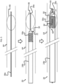
- FIG. 5 is a schematic illustration showing the delivery of apparatus 20 to a thrombus 66, which is located within a blood vessel 64 of a subject, in accordance with some embodiments of the present invention.
- wire 28a is navigated, under fluoroscopy or any other suitable imaging modality, through the vasculature of the subject, until the wire reaches blood vessel 64. Subsequently, wire 28a is passed through thrombus 66.
- perforated tube 22 is inserted into the vasculature of the subject, and is then navigated, through the vasculature, to blood vessel 64. (Perforations 34 are not shown in this portion of the figure.) Subsequently, tube 22 is navigated through the vasculature, until, as shown in the bottom portion of Fig.
- tube 22 may be navigated through the vasculature until the largest perforations are aligned with the proximal end 68 of the thrombus.
- the wire may be withdrawn into tube 22, e.g., until the distal tip of the wire is aligned with the distalmost perforation(s).
- the withdrawal of the wire into the tube increases the proportion of the electric current that flows through the perforations while the voltage is applied. Furthermore, the withdrawal of the wire into the tube facilitates the aspiration of any bubbles that form near the wire, since most or all of these bubbles form within the tube.
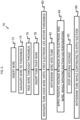
- Fig. 6 is a flow diagram for a method 70 for removing a thrombus from a body of a subject, in accordance with some embodiments of the present invention.
- wire 28a is inserted into the subject.
- wire-navigating step 74 wire 28a is navigated to the thrombus.
- wire 28a is passed through the thrombus, as described above with reference to the top portion of Fig. 5 .
- tube-inserting step 78 tube 22 is inserted, over wire 28a, into the subject.
- Tube 22 is then navigated over the wire, at a tube-navigating step 80, until outer electrode 24 lies at least partly within the thrombus, as described above with reference to the middle and bottom portions of Fig. 5 .
- a wire-withdrawing step 82 the wire is withdrawn into the tube, such that the distal end of the wire is disposed within the distal end of the tube, opposite the perforations.
- voltage source 32 applies a positive voltage between the outer electrode and the wire, while a pump, or other suitable suction-applying device, applies suction to the thrombus via the perforations in the tube.
- the applied voltage causes electric current to flow through the perforations, such that the outer electrode attracts the thrombus.
- the applied suction supplements the applied voltage by pulling the thrombus radially inward, toward the tube, and may further aspirate any detached portions of the thrombus through the distal opening of the tube while the voltage is applied.
- the application of suction begins before the application of voltage.
- the voltage is applied for a duration that is sufficient for the thrombus to adhere to the outer electrode, without exposing the subject to any unnecessary risk.
- this duration may be between one second and 10 minutes, such as between 5 seconds and 5 minutes, e.g., between 10 seconds and 2 minutes.
- the application of the voltage is stopped, at a voltage-stopping step 85.
- the thrombus is removed from the body of the subject, by withdrawing the tube, over the wire, from the subject.
- the wire is withdrawn along with the tube, while in other embodiments, the wire is withdrawn only after the tube has been withdrawn.
- the application of suction continues, such as to help keep the thrombus attached to the outer electrode, and/or aspirate any detached portions of the thrombus through the distal end of the tube.
- the application of the voltage may continue during at least part of the time during which the tube is withdrawn.
- the inner electrode does not comprise wire 28a, or wire 28a does not function as a guidewire.
- a separate guidewire instead of wire 28a, is inserted into the subject at wire-inserting step 72.
- Method 70 then proceeds as outlined above, until the completion of tube-navigating step 80.
- the guidewire is withdrawn from the body, and the inner electrode is then inserted into tube 22, until the distal end of the inner electrode is aligned with the distal perforations in the tube.
- applying step 84 along with the subsequent steps, are performed, as outlined above.
- a suction force may be applied together with the positive voltage, and/or prior to or following the application of the voltage. Although this suction force does not draw the thrombus radially inward (due to the lack of perforations in the tube), this suction force may nonetheless aspirate any detached portions of the thrombus through the distal opening of the tube.
- the positive voltage signal that is applied between the electrodes may have any suitable form, such as any of the forms described in US2011/0301594 .
- the voltage signal may be a periodic signal that includes a sequence of pulses, each of these pulses, for example, being shaped as the positive half-wave of a sinusoidal signal, or having a trapezoidal shape.
- the voltage signal may be a direct current (DC) voltage signal.
- the voltage signal is unipolar.
- the amplitude of the voltage may have any suitable value, this amplitude is typically between 0.1 and 100 V, e.g., between 1 and 100 V, such as between 1 and 50 V, or between 4 and 40 V. Such an amplitude is large enough to be effective, yet small enough such as to avoid damaging the tissue near the thrombus.
- each trapezoidal pulse of the applied voltage signal may (i) linearly ramp up from ground level (0 volts) to an amplitude of around 40 volts, over a time period of around 5 milliseconds, (ii) remain constant over a time period of around 5 milliseconds, and then (iii) linearly ramp down to ground level over a time period of around 5 milliseconds. Before the beginning of the subsequent pulse, the voltage may remain at ground level for another time period of around 5 milliseconds.
- the applied voltage signal if pulsatile, may have any suitable frequency, such as between 0.1 Hz to 100 MHz, e.g., around 50 Hz, as in the example immediately above.
- the voltage is applied such that a current having an amplitude of between 0.1 and 4 mA (e.g., 1-3 mA) is passed between the two electrodes.
- voltage source 32 is current-regulated, e.g., to between 0.1 and 4 mA, such as 1-3 mA. In other embodiments, the voltage source is voltage-regulated, e.g., to between 0.1 and 100 V, or any of the smaller subranges outlined above.
- a negative voltage which dissolves the thrombus, is applied between the outer and inner electrodes, by connecting the outer electrode to the negative terminal of voltage source 32, and connecting the inner electrode to the positive terminal. As the negative voltage is applied, the dissolved pieces of thrombus material are aspirated though the distal opening of tube 22.
Landscapes
- Health & Medical Sciences (AREA)
- Surgery (AREA)
- Life Sciences & Earth Sciences (AREA)
- Engineering & Computer Science (AREA)
- Molecular Biology (AREA)
- Animal Behavior & Ethology (AREA)
- Veterinary Medicine (AREA)
- Biomedical Technology (AREA)
- Heart & Thoracic Surgery (AREA)
- Medical Informatics (AREA)
- Public Health (AREA)
- Nuclear Medicine, Radiotherapy & Molecular Imaging (AREA)
- General Health & Medical Sciences (AREA)
- Orthopedic Medicine & Surgery (AREA)
- Vascular Medicine (AREA)
- Cardiology (AREA)
- Physics & Mathematics (AREA)
- Plasma & Fusion (AREA)
- Otolaryngology (AREA)
- Surgical Instruments (AREA)
Claims (12)
- Appareil (20) destiné à l'élimination d'un thrombus (66) à partir d'un corps d'un sujet, l'appareil comprenant :un tube électriquement isolant (22), qui comprend une extrémité distale (30) présentant une paroi circonférentielle (38) qui est façonnée pour définir de multiples perforations (34), disposées en une ou plusieurs rangées (58), configuré pour insertion dans le corps du sujet ;une électrode externe (24), disposée sur l'extrémité distale du tube électriquement isolant sans couvrir entièrement les perforations, de sorte qu'une extrémité proximale (52) d'électrode de l'électrode externe est proximale par rapport à une la plus proximale des perforations et une extrémité distale (54) d'électrode de l'électrode externe est distale par rapport à une la plus distale des perforations, et configurée pour se trouver au moins partiellement à l'intérieur du thrombus alors que le tube électriquement isolant est à l'intérieur du corps du sujet ; etune électrode interne (28), configurée pour se trouver, à l'intérieur du tube, à l'opposé des perforations, alors que l'électrode externe se trouve au moins partiellement à l'intérieur du thrombus ;l'électrode externe étant configurée pour attirer le thrombus alors que l'électrode externe se trouve au moins partiellement à l'intérieur du thrombus et l'électrode interne se trouve à l'opposé des perforations, lorsqu'une tension positive est appliquée entre l'électrode externe et l'électrode interne de sorte que du courant électrique circule à travers les perforations ;caractérisé en ce que l'électrode externe comprend une spirale qui est enroulée autour de l'extrémité distale du tube électriquement isolant ; eten ce que la spirale est enroulée autour de l'extrémité distale du tube électriquement isolant, entre les perforations.
- Appareil selon la revendication 1, dans lequel l'extrémité distale du tube électriquement isolant est façonnée pour définir un orifice distal.
- Appareil selon la revendication 1, dans lequel l'extrémité distale du tube électriquement isolant est fermée.
- Appareil selon l'une quelconque des revendications précédentes, dans lequel les rangées de perforations sont réparties circonférentiellement le long de la paroi circonférentielle.
- Appareil selon l'une quelconque des revendications précédentes, dans lequel, pour chacune des rangées, au moins une des perforations dans la rangée est plus grande que d'autres perforations dans la rangée.
- Appareil selon la revendication 5, dans lequel au moins une la plus proximale des perforations dans la rangée est plus grande que les autres perforations dans la rangée.
- Appareil selon l'une quelconque des revendications précédentes, dans lequel l'électrode interne comprend un fil métallique.
- Appareil selon l'une quelconque des revendications précédentes, dans lequel l'électrode interne comprend un enroulement électriquement conducteur.
- Appareil selon l'une quelconque des revendications précédentes, dans lequel l'électrode interne comprend un treillis électriquement conducteur.
- Appareil selon l'une quelconque des revendications précédentes, dans lequel l'électrode interne comprend un tube électriquement conducteur.
- Appareil selon la revendication 10, dans lequel les perforations sont des premières perforations, et dans lequel le tube électriquement conducteur est façonné pour définir une ou plusieurs secondes perforations qui sont alignées avec les premières perforations.
- Appareil selon l'une quelconque des revendications précédentes, comprenant en outre une pompe, configurée pour faciliter l'élimination du thrombus en appliquant une aspiration sur le thrombus, via les perforations, pendant que la tension est appliquée.
Applications Claiming Priority (2)
| Application Number | Priority Date | Filing Date | Title |
|---|---|---|---|
| US201762474628P | 2017-03-22 | 2017-03-22 | |
| PCT/IB2018/051731 WO2018172891A1 (fr) | 2017-03-22 | 2018-03-15 | Thrombectomie utilisant à la fois des forces électrostatiques et d'aspiration |
Publications (4)
| Publication Number | Publication Date |
|---|---|
| EP3600103A1 EP3600103A1 (fr) | 2020-02-05 |
| EP3600103A4 EP3600103A4 (fr) | 2020-08-12 |
| EP3600103C0 EP3600103C0 (fr) | 2025-01-01 |
| EP3600103B1 true EP3600103B1 (fr) | 2025-01-01 |
Family
ID=63585104
Family Applications (1)
| Application Number | Title | Priority Date | Filing Date |
|---|---|---|---|
| EP18772459.6A Active EP3600103B1 (fr) | 2017-03-22 | 2018-03-15 | Thrombectomie utilisant à la fois des forces électrostatiques et d'aspiration |
Country Status (7)
| Country | Link |
|---|---|
| EP (1) | EP3600103B1 (fr) |
| JP (1) | JP7096600B2 (fr) |
| CN (1) | CN110402117B (fr) |
| AU (1) | AU2018237872B2 (fr) |
| CA (1) | CA3055267A1 (fr) |
| ES (1) | ES3009062T3 (fr) |
| WO (1) | WO2018172891A1 (fr) |
Families Citing this family (56)
| Publication number | Priority date | Publication date | Assignee | Title |
|---|---|---|---|---|
| DE10233085B4 (de) | 2002-07-19 | 2014-02-20 | Dendron Gmbh | Stent mit Führungsdraht |
| EP1986568B1 (fr) | 2006-02-03 | 2017-04-05 | Covidien LP | Procédés et dispositifs servant à rétablir la circulation sanguine dans un système vasculaire bloqué |
| US11202646B2 (en) | 2007-04-17 | 2021-12-21 | Covidien Lp | Articulating retrieval devices |
| US10076346B2 (en) | 2007-04-17 | 2018-09-18 | Covidien Lp | Complex wire formed devices |
| US10123803B2 (en) | 2007-10-17 | 2018-11-13 | Covidien Lp | Methods of managing neurovascular obstructions |
| US11337714B2 (en) | 2007-10-17 | 2022-05-24 | Covidien Lp | Restoring blood flow and clot removal during acute ischemic stroke |
| CN102036611B (zh) | 2007-12-26 | 2015-01-28 | 拉撒路效应公司 | 取回系统及其使用方法 |
| EP2254485B1 (fr) | 2008-02-22 | 2017-08-30 | Covidien LP | Appareil de restauration d'écoulement |
| WO2012009675A2 (fr) | 2010-07-15 | 2012-01-19 | Lazarus Effect, Inc. | Système d'extraction et procédés d'utilisation associé |
| CN103841905B (zh) | 2011-05-23 | 2017-04-12 | 柯惠有限合伙公司 | 取出系统及其使用方法 |
| US11311332B2 (en) | 2011-08-23 | 2022-04-26 | Magneto Thrombectomy Solutions Ltd. | Thrombectomy devices |
| US9072624B2 (en) | 2012-02-23 | 2015-07-07 | Covidien Lp | Luminal stenting |
| US9314248B2 (en) | 2012-11-06 | 2016-04-19 | Covidien Lp | Multi-pivot thrombectomy device |
| US10076399B2 (en) | 2013-09-13 | 2018-09-18 | Covidien Lp | Endovascular device engagement |
| US9592139B2 (en) | 2013-10-04 | 2017-03-14 | Covidien Lp | Stents twisted prior to deployment and untwisted during deployment |
| US9795400B2 (en) | 2013-11-13 | 2017-10-24 | Covidien Lp | Galvanically assisted attachment of medical devices to thrombus |
| US10456560B2 (en) | 2015-02-11 | 2019-10-29 | Covidien Lp | Expandable tip medical devices and methods |
| EP3302311B1 (fr) | 2015-06-03 | 2019-11-20 | Covidien LP | Dispositifs de traitement intravasculaire flexibles |
| EP3352685B1 (fr) | 2015-09-25 | 2019-08-14 | Covidien LP | Système d'administration de dispositif médical |
| US10537344B2 (en) | 2015-10-23 | 2020-01-21 | Covidien Lp | Rotatable connection between an intervention member and a manipulation member of an endovascular device |
| US10874410B2 (en) | 2015-11-04 | 2020-12-29 | Covidien Lp | Clot removal by adhesion |
| US10052185B2 (en) | 2016-02-12 | 2018-08-21 | Covidien Lp | Vascular device marker attachment |
| US10265089B2 (en) | 2016-02-12 | 2019-04-23 | Covidien Lp | Vascular device visibility |
| US12029475B2 (en) | 2017-03-22 | 2024-07-09 | Magneto Thrombectomy Solutions Ltd. | Thrombectomy using both electrostatic and suction forces |
| US10722257B2 (en) | 2017-05-12 | 2020-07-28 | Covidien Lp | Retrieval of material from vessel lumens |
| US11191555B2 (en) | 2017-05-12 | 2021-12-07 | Covidien Lp | Retrieval of material from vessel lumens |
| US11129630B2 (en) | 2017-05-12 | 2021-09-28 | Covidien Lp | Retrieval of material from vessel lumens |
| US10709464B2 (en) | 2017-05-12 | 2020-07-14 | Covidien Lp | Retrieval of material from vessel lumens |
| US11298145B2 (en) | 2017-05-12 | 2022-04-12 | Covidien Lp | Retrieval of material from vessel lumens |
| WO2018226809A1 (fr) | 2017-06-07 | 2018-12-13 | Covidien Lp | Systèmes et procédés de détection d'accidents vasculaires cérébraux |
| EP3638134B1 (fr) | 2017-06-12 | 2023-08-16 | Covidien LP | Outils de gainage pour dispositifs de traitement, ainsi que systèmes associés |
| US10478322B2 (en) | 2017-06-19 | 2019-11-19 | Covidien Lp | Retractor device for transforming a retrieval device from a deployed position to a delivery position |
| US10575864B2 (en) | 2017-06-22 | 2020-03-03 | Covidien Lp | Securing element for resheathing an intravascular device and associated systems and methods |
| US10342686B2 (en) | 2017-08-10 | 2019-07-09 | Covidien Lp | Thin film mesh hybrid for treating vascular defects |
| US10835398B2 (en) | 2017-11-03 | 2020-11-17 | Covidien Lp | Meshes and devices for treating vascular defects |
| WO2019102307A1 (fr) | 2017-11-23 | 2019-05-31 | Magneto Thrombectomy Solutions Ltd. | Dispositifs tubulaires de thrombectomie |
| US10709463B2 (en) | 2017-12-11 | 2020-07-14 | Covidien Lp | Electrically enhanced retrieval of material from vessel lumens |
| US11058444B2 (en) | 2017-12-11 | 2021-07-13 | Covidien Lp | Electrically enhanced retrieval of material from vessel lumens |
| US12004803B2 (en) | 2021-03-15 | 2024-06-11 | Covidien Lp | Thrombectomy treatment system |
| US12318126B2 (en) | 2021-06-25 | 2025-06-03 | Covidien Lp | Current generator for a medical treatment system |
| US11974752B2 (en) | 2019-12-12 | 2024-05-07 | Covidien Lp | Electrically enhanced retrieval of material from vessel lumens |
| EP3810005B1 (fr) * | 2018-06-20 | 2023-10-25 | Magneto Thrombectomy Solutions Ltd. | Dispositifs de thrombectomie |
| US20190388107A1 (en) * | 2018-06-22 | 2019-12-26 | Covidien Lp | Electrically enhanced retrieval of material from vessel lumens |
| WO2020174326A1 (fr) * | 2019-02-25 | 2020-09-03 | Magneto Thrombectomy Solutions Ltd. | Dispositifs de thrombectomie multi-lumières |
| US11612430B2 (en) | 2019-03-19 | 2023-03-28 | Covidien Lp | Electrically enhanced retrieval of material from vessel lumens |
| US11523838B2 (en) | 2019-06-12 | 2022-12-13 | Covidien Lp | Retrieval of material from corporeal lumens |
| US11191558B2 (en) | 2019-06-12 | 2021-12-07 | Covidien Lp | Retrieval of material from corporeal lumens |
| US11395668B2 (en) | 2019-12-12 | 2022-07-26 | Covidien Lp | Electrically enhanced retrieval of material from vessel lumens |
| US12263020B2 (en) | 2020-02-17 | 2025-04-01 | Covidien Lp | Systems and methods for detecting strokes |
| US12364397B2 (en) | 2020-02-17 | 2025-07-22 | Covidien Lp | Systems and methods for detecting strokes |
| EP4203770A1 (fr) | 2020-08-28 | 2023-07-05 | Covidien LP | Détection d'états de patient au moyen de signaux détectés sur ou à proximité de la tête |
| EP4213747A4 (fr) * | 2020-09-16 | 2024-10-16 | Magneto Thrombectomy Solutions Ltd. | Éléments électrodes multicouches expansibles pour des procédures de thrombectomie |
| US11963713B2 (en) | 2021-06-02 | 2024-04-23 | Covidien Lp | Medical treatment system |
| US11944374B2 (en) | 2021-08-30 | 2024-04-02 | Covidien Lp | Electrical signals for retrieval of material from vessel lumens |
| US12076020B2 (en) | 2021-11-18 | 2024-09-03 | Covidien Lp | Retrieval of material from corporeal lumens |
| CN121570220B (zh) * | 2026-01-27 | 2026-03-31 | 上海畅德医疗科技有限公司 | 取栓支架及取栓系统 |
Citations (1)
| Publication number | Priority date | Publication date | Assignee | Title |
|---|---|---|---|---|
| US20070027448A1 (en) * | 2005-07-27 | 2007-02-01 | Sauray Paul | Multipolar, virtual-electrode catheter with at least one surface electrode and method for ablation |
Family Cites Families (33)
| Publication number | Priority date | Publication date | Assignee | Title |
|---|---|---|---|---|
| US4998933A (en) * | 1988-06-10 | 1991-03-12 | Advanced Angioplasty Products, Inc. | Thermal angioplasty catheter and method |
| US5542928A (en) * | 1991-05-17 | 1996-08-06 | Innerdyne, Inc. | Method and device for thermal ablation having improved heat transfer |
| DE4139029C2 (de) * | 1991-11-27 | 1996-05-23 | Erbe Elektromedizin | Einrichtung zur Koagulation biologischer Gewebe |
| US6190381B1 (en) * | 1995-06-07 | 2001-02-20 | Arthrocare Corporation | Methods for tissue resection, ablation and aspiration |
| US6179824B1 (en) * | 1993-05-10 | 2001-01-30 | Arthrocare Corporation | System and methods for electrosurgical restenosis of body lumens |
| ATE222732T1 (de) * | 1993-05-10 | 2002-09-15 | Arthrocare Corp | Vorrichtung zum chirurgischen schneiden |
| US5722401A (en) * | 1994-10-19 | 1998-03-03 | Cardiac Pathways Corporation | Endocardial mapping and/or ablation catheter probe |
| JPH1057392A (ja) * | 1996-08-22 | 1998-03-03 | Nippon Zeon Co Ltd | 電気手術用処置器具 |
| CA2266073C (fr) * | 1996-10-02 | 2006-08-08 | Medtronic, Inc. | Instrument a fluide pour electrocauterisation |
| AU7141198A (en) | 1997-06-13 | 1998-12-30 | Arthrocare Corporation | Electrosurgical systems and methods for recanalization of occluded body lumens |
| US6855143B2 (en) | 1997-06-13 | 2005-02-15 | Arthrocare Corporation | Electrosurgical systems and methods for recanalization of occluded body lumens |
| US20040073243A1 (en) | 2000-06-29 | 2004-04-15 | Concentric Medical, Inc., A Delaware Corporation | Systems, methods and devices for removing obstructions from a blood vessel |
| US6730104B1 (en) * | 2000-06-29 | 2004-05-04 | Concentric Medical, Inc. | Methods and devices for removing an obstruction from a blood vessel |
| US6761718B2 (en) * | 2001-09-06 | 2004-07-13 | Children's Medical Center Corp. | Direction-oriented and spatially controlled bipolar coagulator for in-situ cauterization of adherent cranial tissue occluding a ventricular catheter previously implanted in-vivo |
| US8496653B2 (en) * | 2007-04-23 | 2013-07-30 | Boston Scientific Scimed, Inc. | Thrombus removal |
| EP2346431A4 (fr) | 2008-11-03 | 2012-10-03 | Univ Ben Gurion | Procédé et appareil de dissolution de thrombus / de thrombectomie au moyen d'un dispositif de cathéter à électrode |
| US8353858B2 (en) * | 2009-06-03 | 2013-01-15 | Medrad, Inc. | Rapid exchange fluid jet catheter and method |
| US9216299B2 (en) * | 2009-10-21 | 2015-12-22 | Thomas J. Wolfe | Electromagnetic pathologic lesion treatment system and method |
| CN102596082B (zh) * | 2009-11-10 | 2015-02-18 | 卡尔迪雅(天津)医疗器械有限公司司 | 中空体腔内消融装置 |
| US8920415B2 (en) * | 2009-12-16 | 2014-12-30 | Biosense Webster (Israel) Ltd. | Catheter with helical electrode |
| US20110218528A1 (en) * | 2010-03-05 | 2011-09-08 | Retro Vascular, Inc. | Anatomical structure access and penetration |
| WO2011111410A1 (fr) * | 2010-03-11 | 2011-09-15 | テルモ株式会社 | Dispositif médical |
| DE102010014778A1 (de) * | 2010-04-13 | 2011-10-13 | Acandis Gmbh & Co. Kg | Medizinische Vorrichtung zum Entfernen von Konkrementen aus Körperhohlorganen |
| US10765473B2 (en) | 2010-11-08 | 2020-09-08 | Baylis Medical Company Inc. | Electrosurgical device having a lumen |
| US9750565B2 (en) * | 2011-09-30 | 2017-09-05 | Medtronic Advanced Energy Llc | Electrosurgical balloons |
| CN104271059B (zh) * | 2012-03-02 | 2017-05-10 | 国立研究开发法人科学技术振兴机构 | 气泡喷出构件及其制造方法、气液喷出构件及其制造方法、局部消融装置及局部消融方法、注射装置及注射方法 |
| JP5874549B2 (ja) | 2012-06-29 | 2016-03-02 | 三菱自動車工業株式会社 | 電動車両 |
| US8888788B2 (en) * | 2012-08-06 | 2014-11-18 | Shockwave Medical, Inc. | Low profile electrodes for an angioplasty shock wave catheter |
| WO2014151123A1 (fr) * | 2013-03-15 | 2014-09-25 | Microvention, Inc. | Système et procédé de suppression d'une obstruction à composants multiples |
| JP6883986B2 (ja) * | 2013-11-18 | 2021-06-09 | コーニンクレッカ フィリップス エヌ ヴェKoninklijke Philips N.V. | 治療用エネルギ送達を含む治療カテーテル |
| CN104224318A (zh) * | 2014-09-28 | 2014-12-24 | 大连顺达微创科技有限公司 | 一种抗粘附等离子体手术电极 |
| CN104207844B (zh) * | 2014-09-28 | 2017-01-11 | 大连顺达微创科技有限公司 | 一种管状电极内侧供液方式的等离子体手术电极 |
| US10016304B2 (en) * | 2015-07-16 | 2018-07-10 | Tusker Medical, Inc. | Earplug assembly for iontophoresis system |
-
2018
- 2018-03-15 EP EP18772459.6A patent/EP3600103B1/fr active Active
- 2018-03-15 JP JP2019546193A patent/JP7096600B2/ja active Active
- 2018-03-15 ES ES18772459T patent/ES3009062T3/es active Active
- 2018-03-15 WO PCT/IB2018/051731 patent/WO2018172891A1/fr not_active Ceased
- 2018-03-15 CA CA3055267A patent/CA3055267A1/fr active Pending
- 2018-03-15 CN CN201880017216.5A patent/CN110402117B/zh active Active
- 2018-03-15 AU AU2018237872A patent/AU2018237872B2/en active Active
Patent Citations (1)
| Publication number | Priority date | Publication date | Assignee | Title |
|---|---|---|---|---|
| US20070027448A1 (en) * | 2005-07-27 | 2007-02-01 | Sauray Paul | Multipolar, virtual-electrode catheter with at least one surface electrode and method for ablation |
Also Published As
| Publication number | Publication date |
|---|---|
| AU2018237872A1 (en) | 2019-09-05 |
| CN110402117A (zh) | 2019-11-01 |
| EP3600103A4 (fr) | 2020-08-12 |
| CA3055267A1 (fr) | 2018-09-27 |
| ES3009062T3 (en) | 2025-03-25 |
| WO2018172891A1 (fr) | 2018-09-27 |
| EP3600103A1 (fr) | 2020-02-05 |
| JP7096600B2 (ja) | 2022-07-06 |
| EP3600103C0 (fr) | 2025-01-01 |
| JP2020511205A (ja) | 2020-04-16 |
| CN110402117B (zh) | 2022-08-05 |
| AU2018237872B2 (en) | 2020-07-09 |
Similar Documents
| Publication | Publication Date | Title |
|---|---|---|
| EP3600103B1 (fr) | Thrombectomie utilisant à la fois des forces électrostatiques et d'aspiration | |
| US12029475B2 (en) | Thrombectomy using both electrostatic and suction forces | |
| US11311332B2 (en) | Thrombectomy devices | |
| US12185961B2 (en) | Electrically enhanced retrieval of material from vessel lumens | |
| EP4098212B1 (fr) | Système de traitement médical | |
| US20230255653A1 (en) | Tubular Thrombectomy Devices | |
| AU2018206023B2 (en) | Thrombectomy devices | |
| US10709463B2 (en) | Electrically enhanced retrieval of material from vessel lumens | |
| EP3810005B1 (fr) | Dispositifs de thrombectomie | |
| EP4098213B1 (fr) | Système de traitement médical | |
| US20220071697A1 (en) | Multi-lumen thrombectomy devices | |
| CN116685278A (zh) | 从血管内腔电增强取出材料 | |
| EP4059451B1 (fr) | Système de traitement médical | |
| EP4338692B1 (fr) | Extraction de matériau des lumières vasculaires | |
| US20220211429A1 (en) | Electrode Assemblies for Measuring Impedance |
Legal Events
| Date | Code | Title | Description |
|---|---|---|---|
| STAA | Information on the status of an ep patent application or granted ep patent |
Free format text: STATUS: THE INTERNATIONAL PUBLICATION HAS BEEN MADE |
|
| PUAI | Public reference made under article 153(3) epc to a published international application that has entered the european phase |
Free format text: ORIGINAL CODE: 0009012 |
|
| STAA | Information on the status of an ep patent application or granted ep patent |
Free format text: STATUS: REQUEST FOR EXAMINATION WAS MADE |
|
| 17P | Request for examination filed |
Effective date: 20190819 |
|
| AK | Designated contracting states |
Kind code of ref document: A1 Designated state(s): AL AT BE BG CH CY CZ DE DK EE ES FI FR GB GR HR HU IE IS IT LI LT LU LV MC MK MT NL NO PL PT RO RS SE SI SK SM TR |
|
| AX | Request for extension of the european patent |
Extension state: BA ME |
|
| DAV | Request for validation of the european patent (deleted) | ||
| DAX | Request for extension of the european patent (deleted) | ||
| A4 | Supplementary search report drawn up and despatched |
Effective date: 20200710 |
|
| RIC1 | Information provided on ipc code assigned before grant |
Ipc: A61N 1/05 20060101ALI20200706BHEP Ipc: A61B 18/14 20060101AFI20200706BHEP |
|
| STAA | Information on the status of an ep patent application or granted ep patent |
Free format text: STATUS: EXAMINATION IS IN PROGRESS |
|
| 17Q | First examination report despatched |
Effective date: 20231213 |
|
| GRAP | Despatch of communication of intention to grant a patent |
Free format text: ORIGINAL CODE: EPIDOSNIGR1 |
|
| STAA | Information on the status of an ep patent application or granted ep patent |
Free format text: STATUS: GRANT OF PATENT IS INTENDED |
|
| INTG | Intention to grant announced |
Effective date: 20240726 |
|
| GRAS | Grant fee paid |
Free format text: ORIGINAL CODE: EPIDOSNIGR3 |
|
| GRAA | (expected) grant |
Free format text: ORIGINAL CODE: 0009210 |
|
| STAA | Information on the status of an ep patent application or granted ep patent |
Free format text: STATUS: THE PATENT HAS BEEN GRANTED |
|
| AK | Designated contracting states |
Kind code of ref document: B1 Designated state(s): AL AT BE BG CH CY CZ DE DK EE ES FI FR GB GR HR HU IE IS IT LI LT LU LV MC MK MT NL NO PL PT RO RS SE SI SK SM TR |
|
| REG | Reference to a national code |
Ref country code: GB Ref legal event code: FG4D |
|
| REG | Reference to a national code |
Ref country code: CH Ref legal event code: EP |
|
| REG | Reference to a national code |
Ref country code: DE Ref legal event code: R096 Ref document number: 602018078129 Country of ref document: DE |
|
| REG | Reference to a national code |
Ref country code: IE Ref legal event code: FG4D |
|
| U01 | Request for unitary effect filed |
Effective date: 20250131 |
|
| U07 | Unitary effect registered |
Designated state(s): AT BE BG DE DK EE FI FR IT LT LU LV MT NL PT RO SE SI Effective date: 20250206 |
|
| U20 | Renewal fee for the european patent with unitary effect paid |
Year of fee payment: 8 Effective date: 20250206 |
|
| REG | Reference to a national code |
Ref country code: ES Ref legal event code: FG2A Ref document number: 3009062 Country of ref document: ES Kind code of ref document: T3 Effective date: 20250325 |
|
| PG25 | Lapsed in a contracting state [announced via postgrant information from national office to epo] |
Ref country code: PL Free format text: LAPSE BECAUSE OF FAILURE TO SUBMIT A TRANSLATION OF THE DESCRIPTION OR TO PAY THE FEE WITHIN THE PRESCRIBED TIME-LIMIT Effective date: 20250101 |
|
| PGFP | Annual fee paid to national office [announced via postgrant information from national office to epo] |
Ref country code: ES Payment date: 20250402 Year of fee payment: 8 |
|
| PG25 | Lapsed in a contracting state [announced via postgrant information from national office to epo] |
Ref country code: NO Free format text: LAPSE BECAUSE OF FAILURE TO SUBMIT A TRANSLATION OF THE DESCRIPTION OR TO PAY THE FEE WITHIN THE PRESCRIBED TIME-LIMIT Effective date: 20250401 Ref country code: IS Free format text: LAPSE BECAUSE OF FAILURE TO SUBMIT A TRANSLATION OF THE DESCRIPTION OR TO PAY THE FEE WITHIN THE PRESCRIBED TIME-LIMIT Effective date: 20250501 |
|
| PG25 | Lapsed in a contracting state [announced via postgrant information from national office to epo] |
Ref country code: HR Free format text: LAPSE BECAUSE OF FAILURE TO SUBMIT A TRANSLATION OF THE DESCRIPTION OR TO PAY THE FEE WITHIN THE PRESCRIBED TIME-LIMIT Effective date: 20250101 |
|
| PG25 | Lapsed in a contracting state [announced via postgrant information from national office to epo] |
Ref country code: GR Free format text: LAPSE BECAUSE OF FAILURE TO SUBMIT A TRANSLATION OF THE DESCRIPTION OR TO PAY THE FEE WITHIN THE PRESCRIBED TIME-LIMIT Effective date: 20250402 |
|
| PG25 | Lapsed in a contracting state [announced via postgrant information from national office to epo] |
Ref country code: CZ Free format text: LAPSE BECAUSE OF FAILURE TO SUBMIT A TRANSLATION OF THE DESCRIPTION OR TO PAY THE FEE WITHIN THE PRESCRIBED TIME-LIMIT Effective date: 20250101 |
|
| PG25 | Lapsed in a contracting state [announced via postgrant information from national office to epo] |
Ref country code: SM Free format text: LAPSE BECAUSE OF FAILURE TO SUBMIT A TRANSLATION OF THE DESCRIPTION OR TO PAY THE FEE WITHIN THE PRESCRIBED TIME-LIMIT Effective date: 20250101 |
|
| PG25 | Lapsed in a contracting state [announced via postgrant information from national office to epo] |
Ref country code: MC Free format text: LAPSE BECAUSE OF FAILURE TO SUBMIT A TRANSLATION OF THE DESCRIPTION OR TO PAY THE FEE WITHIN THE PRESCRIBED TIME-LIMIT Effective date: 20250101 |
|
| REG | Reference to a national code |
Ref country code: CH Ref legal event code: H13 Free format text: ST27 STATUS EVENT CODE: U-0-0-H10-H13 (AS PROVIDED BY THE NATIONAL OFFICE) Effective date: 20251024 |
|
| PG25 | Lapsed in a contracting state [announced via postgrant information from national office to epo] |
Ref country code: SK Free format text: LAPSE BECAUSE OF FAILURE TO SUBMIT A TRANSLATION OF THE DESCRIPTION OR TO PAY THE FEE WITHIN THE PRESCRIBED TIME-LIMIT Effective date: 20250101 |
|
| PLBE | No opposition filed within time limit |
Free format text: ORIGINAL CODE: 0009261 |
|
| STAA | Information on the status of an ep patent application or granted ep patent |
Free format text: STATUS: NO OPPOSITION FILED WITHIN TIME LIMIT |
|
| 26N | No opposition filed |
Effective date: 20251002 |
|
| PG25 | Lapsed in a contracting state [announced via postgrant information from national office to epo] |
Ref country code: CH Free format text: LAPSE BECAUSE OF NON-PAYMENT OF DUE FEES Effective date: 20250331 |
|
| PG25 | Lapsed in a contracting state [announced via postgrant information from national office to epo] |
Ref country code: IE Free format text: LAPSE BECAUSE OF NON-PAYMENT OF DUE FEES Effective date: 20250315 |
|
| PGFP | Annual fee paid to national office [announced via postgrant information from national office to epo] |
Ref country code: GB Payment date: 20260324 Year of fee payment: 9 |
|
| U20 | Renewal fee for the european patent with unitary effect paid |
Year of fee payment: 9 Effective date: 20260326 |