EP3600637B1 - Acid mixing system and method - Google Patents
Acid mixing system and method Download PDFInfo
- Publication number
- EP3600637B1 EP3600637B1 EP18717774.6A EP18717774A EP3600637B1 EP 3600637 B1 EP3600637 B1 EP 3600637B1 EP 18717774 A EP18717774 A EP 18717774A EP 3600637 B1 EP3600637 B1 EP 3600637B1
- Authority
- EP
- European Patent Office
- Prior art keywords
- solution
- controller
- powder
- batch
- mix
- Prior art date
- Legal status (The legal status is an assumption and is not a legal conclusion. Google has not performed a legal analysis and makes no representation as to the accuracy of the status listed.)
- Active
Links
Images


Classifications
-
- A—HUMAN NECESSITIES
- A61—MEDICAL OR VETERINARY SCIENCE; HYGIENE
- A61M—DEVICES FOR INTRODUCING MEDIA INTO, OR ONTO, THE BODY; DEVICES FOR TRANSDUCING BODY MEDIA OR FOR TAKING MEDIA FROM THE BODY; DEVICES FOR PRODUCING OR ENDING SLEEP OR STUPOR
- A61M1/00—Suction or pumping devices for medical purposes; Devices for carrying-off, for treatment of, or for carrying-over, body-liquids; Drainage systems
- A61M1/14—Dialysis systems; Artificial kidneys; Blood oxygenators ; Reciprocating systems for treatment of body fluids, e.g. single needle systems for hemofiltration or pheresis
- A61M1/16—Dialysis systems; Artificial kidneys; Blood oxygenators ; Reciprocating systems for treatment of body fluids, e.g. single needle systems for hemofiltration or pheresis with membranes
- A61M1/1654—Dialysates therefor
- A61M1/1656—Apparatus for preparing dialysates
- A61M1/1666—Apparatus for preparing dialysates by dissolving solids
-
- B—PERFORMING OPERATIONS; TRANSPORTING
- B01—PHYSICAL OR CHEMICAL PROCESSES OR APPARATUS IN GENERAL
- B01F—MIXING, e.g. DISSOLVING, EMULSIFYING OR DISPERSING
- B01F21/00—Dissolving
- B01F21/20—Dissolving using flow mixing
-
- B—PERFORMING OPERATIONS; TRANSPORTING
- B01—PHYSICAL OR CHEMICAL PROCESSES OR APPARATUS IN GENERAL
- B01F—MIXING, e.g. DISSOLVING, EMULSIFYING OR DISPERSING
- B01F21/00—Dissolving
- B01F21/30—Workflow diagrams or layout of plants, e.g. flow charts; Details of workflow diagrams or layout of plants, e.g. controlling means
-
- B—PERFORMING OPERATIONS; TRANSPORTING
- B01—PHYSICAL OR CHEMICAL PROCESSES OR APPARATUS IN GENERAL
- B01F—MIXING, e.g. DISSOLVING, EMULSIFYING OR DISPERSING
- B01F23/00—Mixing according to the phases to be mixed, e.g. dispersing or emulsifying
- B01F23/50—Mixing liquids with solids
- B01F23/59—Mixing systems, i.e. flow charts or diagrams
-
- B—PERFORMING OPERATIONS; TRANSPORTING
- B01—PHYSICAL OR CHEMICAL PROCESSES OR APPARATUS IN GENERAL
- B01F—MIXING, e.g. DISSOLVING, EMULSIFYING OR DISPERSING
- B01F25/00—Flow mixers; Mixers for falling materials, e.g. solid particles
- B01F25/30—Injector mixers
- B01F25/31—Injector mixers in conduits or tubes through which the main component flows
- B01F25/312—Injector mixers in conduits or tubes through which the main component flows with Venturi elements; Details thereof
-
- B—PERFORMING OPERATIONS; TRANSPORTING
- B01—PHYSICAL OR CHEMICAL PROCESSES OR APPARATUS IN GENERAL
- B01F—MIXING, e.g. DISSOLVING, EMULSIFYING OR DISPERSING
- B01F25/00—Flow mixers; Mixers for falling materials, e.g. solid particles
- B01F25/50—Circulation mixers, e.g. wherein at least part of the mixture is discharged from and reintroduced into a receptacle
- B01F25/51—Circulation mixers, e.g. wherein at least part of the mixture is discharged from and reintroduced into a receptacle in which the mixture is circulated through a set of tubes, e.g. with gradual introduction of a component into the circulating flow
-
- B—PERFORMING OPERATIONS; TRANSPORTING
- B01—PHYSICAL OR CHEMICAL PROCESSES OR APPARATUS IN GENERAL
- B01F—MIXING, e.g. DISSOLVING, EMULSIFYING OR DISPERSING
- B01F25/00—Flow mixers; Mixers for falling materials, e.g. solid particles
- B01F25/50—Circulation mixers, e.g. wherein at least part of the mixture is discharged from and reintroduced into a receptacle
- B01F25/53—Circulation mixers, e.g. wherein at least part of the mixture is discharged from and reintroduced into a receptacle in which the mixture is discharged from and reintroduced into a receptacle through a recirculation tube, into which an additional component is introduced
-
- B—PERFORMING OPERATIONS; TRANSPORTING
- B01—PHYSICAL OR CHEMICAL PROCESSES OR APPARATUS IN GENERAL
- B01F—MIXING, e.g. DISSOLVING, EMULSIFYING OR DISPERSING
- B01F35/00—Accessories for mixers; Auxiliary operations or auxiliary devices; Parts or details of general application
- B01F35/20—Measuring; Control or regulation
- B01F35/21—Measuring
- B01F35/211—Measuring of the operational parameters
- B01F35/2113—Pressure
-
- B—PERFORMING OPERATIONS; TRANSPORTING
- B01—PHYSICAL OR CHEMICAL PROCESSES OR APPARATUS IN GENERAL
- B01F—MIXING, e.g. DISSOLVING, EMULSIFYING OR DISPERSING
- B01F35/00—Accessories for mixers; Auxiliary operations or auxiliary devices; Parts or details of general application
- B01F35/20—Measuring; Control or regulation
- B01F35/21—Measuring
- B01F35/2133—Electrical conductivity or dielectric constant of the mixture
-
- B—PERFORMING OPERATIONS; TRANSPORTING
- B01—PHYSICAL OR CHEMICAL PROCESSES OR APPARATUS IN GENERAL
- B01F—MIXING, e.g. DISSOLVING, EMULSIFYING OR DISPERSING
- B01F35/00—Accessories for mixers; Auxiliary operations or auxiliary devices; Parts or details of general application
- B01F35/20—Measuring; Control or regulation
- B01F35/21—Measuring
- B01F35/2134—Density or solids or particle number
-
- B—PERFORMING OPERATIONS; TRANSPORTING
- B01—PHYSICAL OR CHEMICAL PROCESSES OR APPARATUS IN GENERAL
- B01F—MIXING, e.g. DISSOLVING, EMULSIFYING OR DISPERSING
- B01F35/00—Accessories for mixers; Auxiliary operations or auxiliary devices; Parts or details of general application
- B01F35/20—Measuring; Control or regulation
- B01F35/22—Control or regulation
- B01F35/2201—Control or regulation characterised by the type of control technique used
- B01F35/2207—Use of data, i.e. barcodes, 3D codes or similar type of tagging information, as instruction or identification codes for controlling the computer programs, e.g. for manipulation, handling, production or compounding in mixing plants
-
- B—PERFORMING OPERATIONS; TRANSPORTING
- B01—PHYSICAL OR CHEMICAL PROCESSES OR APPARATUS IN GENERAL
- B01F—MIXING, e.g. DISSOLVING, EMULSIFYING OR DISPERSING
- B01F35/00—Accessories for mixers; Auxiliary operations or auxiliary devices; Parts or details of general application
- B01F35/71—Feed mechanisms
- B01F35/717—Feed mechanisms characterised by the means for feeding the components to the mixer
- B01F35/7173—Feed mechanisms characterised by the means for feeding the components to the mixer using gravity, e.g. from a hopper
- B01F35/71731—Feed mechanisms characterised by the means for feeding the components to the mixer using gravity, e.g. from a hopper using a hopper
-
- A—HUMAN NECESSITIES
- A61—MEDICAL OR VETERINARY SCIENCE; HYGIENE
- A61M—DEVICES FOR INTRODUCING MEDIA INTO, OR ONTO, THE BODY; DEVICES FOR TRANSDUCING BODY MEDIA OR FOR TAKING MEDIA FROM THE BODY; DEVICES FOR PRODUCING OR ENDING SLEEP OR STUPOR
- A61M2205/00—General characteristics of the apparatus
- A61M2205/33—Controlling, regulating or measuring
- A61M2205/3317—Electromagnetic, inductive or dielectric measuring means
-
- A—HUMAN NECESSITIES
- A61—MEDICAL OR VETERINARY SCIENCE; HYGIENE
- A61M—DEVICES FOR INTRODUCING MEDIA INTO, OR ONTO, THE BODY; DEVICES FOR TRANSDUCING BODY MEDIA OR FOR TAKING MEDIA FROM THE BODY; DEVICES FOR PRODUCING OR ENDING SLEEP OR STUPOR
- A61M2205/00—General characteristics of the apparatus
- A61M2205/33—Controlling, regulating or measuring
- A61M2205/3331—Pressure; Flow
-
- A—HUMAN NECESSITIES
- A61—MEDICAL OR VETERINARY SCIENCE; HYGIENE
- A61M—DEVICES FOR INTRODUCING MEDIA INTO, OR ONTO, THE BODY; DEVICES FOR TRANSDUCING BODY MEDIA OR FOR TAKING MEDIA FROM THE BODY; DEVICES FOR PRODUCING OR ENDING SLEEP OR STUPOR
- A61M2205/00—General characteristics of the apparatus
- A61M2205/33—Controlling, regulating or measuring
- A61M2205/3379—Masses, volumes, levels of fluids in reservoirs, flow rates
- A61M2205/3382—Upper level detectors
-
- A—HUMAN NECESSITIES
- A61—MEDICAL OR VETERINARY SCIENCE; HYGIENE
- A61M—DEVICES FOR INTRODUCING MEDIA INTO, OR ONTO, THE BODY; DEVICES FOR TRANSDUCING BODY MEDIA OR FOR TAKING MEDIA FROM THE BODY; DEVICES FOR PRODUCING OR ENDING SLEEP OR STUPOR
- A61M2205/00—General characteristics of the apparatus
- A61M2205/35—Communication
- A61M2205/3576—Communication with non implanted data transmission devices, e.g. using external transmitter or receiver
- A61M2205/3592—Communication with non implanted data transmission devices, e.g. using external transmitter or receiver using telemetric means, e.g. radio or optical transmission
-
- A—HUMAN NECESSITIES
- A61—MEDICAL OR VETERINARY SCIENCE; HYGIENE
- A61M—DEVICES FOR INTRODUCING MEDIA INTO, OR ONTO, THE BODY; DEVICES FOR TRANSDUCING BODY MEDIA OR FOR TAKING MEDIA FROM THE BODY; DEVICES FOR PRODUCING OR ENDING SLEEP OR STUPOR
- A61M2205/00—General characteristics of the apparatus
- A61M2205/50—General characteristics of the apparatus with microprocessors or computers
- A61M2205/502—User interfaces, e.g. screens or keyboards
-
- A—HUMAN NECESSITIES
- A61—MEDICAL OR VETERINARY SCIENCE; HYGIENE
- A61M—DEVICES FOR INTRODUCING MEDIA INTO, OR ONTO, THE BODY; DEVICES FOR TRANSDUCING BODY MEDIA OR FOR TAKING MEDIA FROM THE BODY; DEVICES FOR PRODUCING OR ENDING SLEEP OR STUPOR
- A61M2205/00—General characteristics of the apparatus
- A61M2205/60—General characteristics of the apparatus with identification means
- A61M2205/6063—Optical identification systems
- A61M2205/6072—Bar codes
-
- B—PERFORMING OPERATIONS; TRANSPORTING
- B01—PHYSICAL OR CHEMICAL PROCESSES OR APPARATUS IN GENERAL
- B01F—MIXING, e.g. DISSOLVING, EMULSIFYING OR DISPERSING
- B01F2101/00—Mixing characterised by the nature of the mixed materials or by the application field
- B01F2101/2202—Mixing compositions or mixers in the medical or veterinary field
-
- B—PERFORMING OPERATIONS; TRANSPORTING
- B01—PHYSICAL OR CHEMICAL PROCESSES OR APPARATUS IN GENERAL
- B01F—MIXING, e.g. DISSOLVING, EMULSIFYING OR DISPERSING
- B01F23/00—Mixing according to the phases to be mixed, e.g. dispersing or emulsifying
- B01F23/50—Mixing liquids with solids
- B01F23/56—Mixing liquids with solids by introducing solids in liquids, e.g. dispersing or dissolving
-
- G—PHYSICS
- G01—MEASURING; TESTING
- G01N—INVESTIGATING OR ANALYSING MATERIALS BY DETERMINING THEIR CHEMICAL OR PHYSICAL PROPERTIES
- G01N9/00—Investigating density or specific gravity of materials; Analysing materials by determining density or specific gravity
- G01N9/26—Investigating density or specific gravity of materials; Analysing materials by determining density or specific gravity by measuring pressure differences
Definitions
- the present invention relates generally to system for mixing a solution using a liquid and a dry powder and more particularly for accurately and automatically mixing an acid solution for use in a hemodialysis system.
- a system in accordance with the preamble of claim 1 is known from WO-A1-00/74833 .
- Various embodiments and aspects of the invention overcome the aforementioned deficiencies in the prior art by providing generally a system for mixing a solution and more particularly a system for automatically mixing and testing an acid solution to produce a solution having a desired pH or concentration.
- a system for mixing an acid solution refer mainly to a system for mixing an acid solution
- the instant system may be utilized to mix any of a wide variety of powders with any of a wide variety of fluids without departing from the scope of the invention.
- the system described herein is not limited to the mixing of acid solutions, but rather may be implemented to mix any solution utilizing a powder or dry material and a liquid or fluid.
- a system for mixing a solution of a dry powder and a fluid includes a hopper having a powder outlet that is in fluid communication with a mix pump line, so that powder may be deposited into the mix pump line and then distributed into a mix tank.
- the hopper powder outlet may be in fluid communication with a control valve that meters or drops powder into mix pump line.
- the mix tank provides an enclosed area in which the solution is mixed and includes a liquid supply inlet, a recirculation line, and a mix solution outlet.
- the solution outlet and recirculation line are also in fluid communication with the mix pump to provide continuous mixing of the liquid and powder as the pump recirculates fluid.
- the mix tank may include a level sensor capable of sensing a level of solution in the mix tank, for example a predetermined volume based on a desired batch.
- a processor or controller is provided, having signal and/or data inputs and signal and/or data outputs for accepting and supplying various electrical signals to and from components of the invention.
- the controller may include a data memory for storing instructions to operate the various invention components as well as an operator interface or equivalent user input to allow an operator to receive data from the system as well as provide user commands.
- a bar code scanner is operatively coupled to the controller via an input, to permit an operator to scan a bar code provided on a powder bag or case, thereby inputting data related to that specific powder bag (or batch) for tracking and verification purposes.
- this feature is useful when mixing solutions for medical uses such as hemodialysis, wherein each quantity of powder input -for example a bag or case of dry acid mix - is tracked by a bar code or similar identifier.
- controller stores the information provided so that each batch that is mixed can be tracked by the powder batch number, manufacturer, sale date, and size, to mention some exemplary but non-limiting data that may be stored and tracked.
- a batch transfer/recirculation line having an RFID interrogator secured proximate a coupling.
- the interrogator is operatively coupled to the controller and interrogates a concomitant RFID tag mounted near the inlet of a storage tank where the transfer coupling is secured when transferring a batch to the storage tank.
- the system permits the transfer.
- the system prohibits the transfer of the solution and provides an alarm through an operator interface to alert an operator to the error.
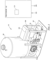
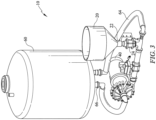
- a mixing system 10 for mixing a powder 1 or dry material and a liquid 2 or fluid into a solution 3 includes a hopper 20 into which the powder 1 may be deposited.
- the hopper 20 includes a powder outlet 22 that is in fluid communication with a mix pump 40 line 42, such that powder may be deposited in to the mix pump 40 line and then distributed into a mix tank 60.
- Hopper 20 powder outlet 22 may be in fluid communication with a control valve 24 that meters or drops powder into mix pump line 42, thereby providing for measured powder input to mix tank 60 by operation of pump 40.
- Mix tank 60 provides an enclosed area in which the solution 3 is mixed and includes a liquid supply inlet 62, a recirculation line 64, and a mix solution outlet 66.
- the solution outlet 66 and recirculation line 64 are also in fluid communication with mix pump 40, so that mix pump 40 may provide continuous mixing of the liquid 2 and powder 1 as pump 40 recirculates fluid through pump line 42 and recirculation line 64.
- mix tank 60 also includes a level sensor 68, or a plurality thereof, capable of sensing a level of solution 3 in mix tank 60 representative of a predetermined volume of solution.
- Level sensors 68 have an output representative of a fluid level detected that is operatively coupled to an input 102 of controller 100.
- controller 100 can be provided with instructions to fill mix tank 60 to a specific volume by monitoring level sensors 68, as will be discussed further herein below.
- a processor 100 or controller having signal and/or data inputs 102 and signal and/or data outputs 104 for accepting and supplying various electrical signals to and from components of the invention.
- Controller 100 includes of a data memory 110 for storing instructions to operate the various invention components as well as an operator interface 120 or equivalent user input to allow an operator to receive and view data and various system 10 operating parameters as well as provide user commands thereto.
- a bar code scanner 130 is operatively coupled to controller 100 via an input 102 thereto, to permit an operator to scan a bar code provided on a powder 1 bag, thereby inputting data related to that specific powder 1 bag (or batch) for tracking and verification purposes.
- controller 100 stores the information provided in each powder 1 bag bar code scanned such that each tank 60 that is mixed can be tracked by the powder 1 batch number, manufacturer, sale date, and size, to mention some exemplary but non-limiting data that may be stored and tracked.
- processor 100 inputs 102 and outputs 104 are in some embodiments operatively coupled to various valves disposed throughout system 10.
- a hopper 20 outlet valve 24 is disposed below powder hopper 20 to release powder 1 into mix pump line 42.
- Hopper outlet valve 24 is operatively coupled to an output 103 of controller 100 to actuate valve 24, and further may include a plurality of operatively coupled signal inputs 102 to controller 100 to indicate an open and/or closed valve 24 position, or a signal input that is indicative of valve 24 position.
- Each valve herein described may be operatively coupled to controller 100 inputs 102 and outputs 104 so that system 10 may operate each valve individually, and monitor the position of each valve through system 10 operation.
- a mixing jets valve 70 is provided in fluid communication with mix pump line 42 to siphon a portion of the fluid 2 circulated through pump 60 into hopper 20, thereby assuring that all powder 1 placed in hopper 20 is ultimately distributed into mix tank 60 by operation of pump 40.
- Mixing jets valve 70 is operatively coupled to controller 100 inputs 102 and outputs 104.
- a water supply inlet valve 80 is operatively coupled to an output 104 of controller 100, such that controller 100 can automatically control the amount of fluid 2 supplied to mix tank 60 according to the programming instructions supplied to the controller 100, as will be discussed further herein below.
- water supply valve 80 may be a three-way valve that permits process water 1 (or fluid) to enter mix tank 60 or provides a fluid communication path for recirculation line 64 from mix pump 40, depending upon valve 80 position.
- an input water valve 84 is operatively coupled to controller 100 and is disposed proximate mix tank 60 to regulate fluid 2 flow into tank 60 when required. Additionally, water supply 2 is also in fluid communication with a spray/rinse valve 86 that supplies water to a spray head 88 for rinsing and cleaning mix tank 60 when desired. Spray/rinse valve 86 is also operatively connected to an output 104 of controller 100 so that a rinse cycle may be initiated through user interface 120 when necessary or alternatively automatically performed after each batch of solution is produced and transferred from mix tank 60, as will be discussed further herein below.
- a shutoff valve 90 operatively coupled to controller 100 may be disposed in fluid communication with mix tank 60 and mix pump 40 to prevent the flow of solution 3 from pump 40 into mix tank 60.
- a three-way drain/transfer valve 94 is disposed in fluid communication with both recirculation line 64 and mix pump line 42.
- the system 10 may include a pressure sensor 140 provided in fluid communication with mix tank 60, having an output 142 operatively coupled to an input 102 of controller 100, said output being representative of the pressure of the solution being mixed in tank 60 at the point where the sensor is disposed.
- pressure sensor 140 is disposed proximate a bottom surface of mix tank 60, so that the pressure sensor 140 detects the pressure of a column of water within tank 60.
- Sensor 140 input 102 to controller 100 may then continuously or periodically monitor solution 3 pressure, which thereby provides an accurate indication of whether sufficient powder 1 and water 2 have been added to mix tank 60 to produce a predetermined solution concentration for a given volume of fluid supplied.
- a hydrostatic pressure sensor 140 may be employed to monitor solution 3 pressure, although a wide variety of pressure sensors may be used without departing from the scope of the invention.
- pressure sensor 140 output 142 is converted by controller 100 to a specific gravity indication based upon the constituent powder 1 ingredients and the fluid 2 supplied for a given batch. In these embodiments pressure is readily converted to specific gravity so that controller 100 can readily verify that a specified batch of solution 3 is properly mixed to the correct concentration.
- system 10 may be used to produce acid concentrate solutions for use in hemodialysis machines.
- a dry acid concentrate powder 1 is typically mixed with purified water 2 to produce the desired concentrate solution.
- a batch of dry acid concentrate powder is purchased or otherwise obtained in a box or case containing, in some embodiments, two blend bags of acid powder and one bag of dextrose.
- a box or case may contain two blend bags of acid powder, one bag of dextrose, and one bag of a citric acid type powder concentrate, such as Citrasate.
- the case or box may include a bar code containing manufacturer and batch information that is scanned into controller 100 by a user using scanner 130 prior to being opened to verify the batch number and other manufacturer information.
- Each bag of dry powder 1 within the case also includes a bar code, each of which is also scanned by a user using bar code scanner 130 when the bag is loaded into hopper 20 so that all bags in a batch are accounted for during the mixing process.
- Controller 100 is provided with specific instructions to prohibit transfer of solution 3 to a final use tank or storage tank where each bag in a batch has not been scanned by system 10. All data scanned into controller 100 is stored for purposes of verifying each batch of solution 3 mixed by system 10.
- output signal 142 from pressure sensor 140 is monitored by controller 100 throughout the mixing process.
- controller 100 begins filling mix tank 60 with a predetermined volume of fluid 2, in this example purified water.
- the controller then monitors level sensor 68 to determine when a predetermined batch volume is reached in mix tank 60, and then turns off input water valve 84.
- Controller 100 then also monitors pressure sensor 140 to determine the exact pressure of the solution 3 in tank 60. For a predetermined volume of solution 3 containing a predetermined volume of water 2 and dry powder 1, the hydrostatic pressure as detected by sensor 140 will be within a very narrow pressure range.
- Solution pressure is used by controller 100 as a proxy for solution concentration, since a solution 3 having a proper concentration will be at a specific pressure for a given volume of solution 3.
- Controller 100 confirms that the pressure range is correct for a batch of solution prior to permitting a user to transfer the batch from mix tank 60. Furthermore, when a pressure that is outside the predetermined range is detected, controller 100 provides an indication to a user through operator interface 120 of an incorrect batch. By monitoring the pressure for a predetermined batch volume, controller 100 can provide an indication of a missing powder bag, and further can prompt the operator that the missing bag was dextrose, dry acid blend, or Citrisate simply by noting the differences in pressure.
- controller 100 may monitor solution 3 pressure via pressure sensor 140 output 142. Where solution 3 pressure for a predetermined volume is out of a predetermined range, controller 100 may actuate water supply 2 inlet valve 80 to provide additional fluid 2 to tank 60. In this embodiment, the inlet valve 80 is only actuated to provide additional water 2 when solution 3 pressure indicates the concentration of solution 3 is too high.
- controller 100 may monitor pressure sensor 140 to determine if solution 3 pressure is out of a predetermined range, either high or low, and then provide a user an indication of improper solution 3 concentration by providing a "concentration high", “concentration low", or “concentration out of range” alarm indication through user interface 120. Controller 100 may be provided with predetermined acceptable solution 3 pressure ranges for a plurality of solution 3 concentrations by volume of solution 3 mixed in tank 60.
- a conductivity sensor 160 may be provided in place of pressure sensor 140, said sensor 160 being disposed in the mix tank 60.
- Conductivity sensor 160 includes an output that is operatively coupled to an input 102 of controller 100 that provides a signal representative of the conductivity of the solution 3 in tank 60. This conductivity measurement is accordingly treated as a proxy for solution 3 concentration, and thus by continuously monitoring the conductivity of solution 3 controller 100 may then continuously adjust powder 1 and/or fluid 2 provided to mix tank 60 to maintain solution conductivity at a predetermined set point.
- conductivity sensor 160 operates in an analogous fashion to pressure sensor 140. Controller 100 is provided with predetermined conductivity ranges for solution 3 concentrations by volume of solution 3 mixed in tank 60, rather than pressure ranges.
- the user interface 120 may provide indications of solution pressure, concentration, specific gravity, and conductivity visible to a user.
- controller 100 may be provided with instructions to provide an audible or visual alarm if the solution being mixed is outside of a predetermined range of pressure, concentration, specific gravity, or conductivity as determined by the sensors. In this case an operator or user can be prompted to take corrective action or "dump" the solution batch and mix a new batch as desired.
- a bag opening system 180 may be provided, wherein a plastic powder 1 bag 4 or equivalent container of powder 1 is placed in bag 4 opening system 180 and is then automatically opened and dispensed into hopper 20.
- Bag opening system 180 may include a bag cutter for opening powder bags 4 and has a bottom portion 182 in fluid communication with hopper 20.
- bag opening system 180 may include a bag holder 184 that secures each powder bag 4 in a fixed position so that the bag cutter can make a consistent opening in each bag 4 and empty substantially all bag 4 contents into powder hopper 20.
- Controller 100 performs a solution 3 mixing process when a user initiates the process using interface 120 to specify what type of solution 3 is being mixed by ingredients, concentration and volume.
- Controller 100 begins filling mix tank 60 with fluid 2, in many cases purified water, by opening valves 80 and 84 and operating pump 40.
- a user or operator then scans a barcode on an acid powder 1 case (or other dry powder case) and then sequentially scans the barcodes of each powder 1 bag in the case and empties the bags into hopper 20.
- Controller 100 then opens powder control valve 24 to begin supplying powder through recirculation line 64 and into tank 60.
- Pressure sensor 140 (or alternatively conductivity sensor 160) is continuously monitored during the mixing process to ensure that the pressure (or conductivity, or specific gravity) sensed thereby is within a predetermined acceptable range for the specified solution 3 batch being mixed.
- user interface 120 prompts an operator that the batch is ready to be transferred from system 10, as discussed further below. If the pressure or conductivity of solution 3 as sensed by sensors 140, 160 is out of a predetermined acceptable range, the operator is prompted to take corrective action or drain the solution 3 batch to waste through drain 96.
- recirculation line 64 may be provided with a coupling 150 or disconnect, or a plurality thereof, that permits it to be separated from system 10.
- An RFID (Radio Frequency Identification) interrogator 152 is disposed on line 64 or coupling 150 for interrogating passive RFID tags 154.
- Interrogator 152 is operatively coupled to controller 100 inputs 102 and outputs 104 to transfer data from a concomitant RFID tag 154.
- an RFID tag 154 is disposed on a solution storage tank 160, proximate a coupling 162 that mates with and engages coupling 150 of line 64.
- RFID tag 154 may include information that is unique to the type of solution 3 stored in a specific storage tank 160.
- solution 3 concentration, solution 3 formula, batch numbers, manufacturer identifiers, powder 1 expiration dataes, and mixing dates may be stored as pertinent data in RFID tag 154. Any data desired to track and verify proper preparation and supply chain information may be stored in RFID tag 154 without departing from the scope of the invention.
- recirculation line 64 is decoupled from system 10 and coupled to storage tank 160.
- RFID interrogator 152 is then disposed proximate RFlD tag 154, and reads the data stored in the RFID tag 154 and supplies the tag 154 data to controller 100, to verify that the type of solution 3 in mix tank 60 is the same as that being stored in storage tank 160.
- controller 100 determines that the solution 3 in mix tank 60 and storage tank 160 are the same, it permits the transfer of solution 3 by operation of mix pump 40.
- a user input transfer button or indication may be provided via operator interface 120 to facilitate the operation.
- controller 100 determines that the solution 3 in mix tank 60 and storage tank 160 are not the same, operator interface 120 provides an audible and/or visual alarm to a user and prohibits the transfer of solution 3 into storage tank 160 until the user resolves the mismatch.
- This feature of the invention prohibits the transfer of incorrect solution 3 batches into a storage tank 160 and is thus useful for medical applications such as hemodialysis where acid solutions 3 must be produced and stored in very specific concentrations for use.
- controller 100 shuts off pump 40 and provides an indication to a user that the transfer process is complete. The user is then free to re-couple line 64 into system 10, and begin a new solution 3 batch.
- controller 100 may initiate a rinse process to clean system 10 after batch transfer.
- fluid 1 is provided through controller 100 operating rinse valve 86 and spray head 88 for a specified time period or volume.
- Pump 40 may be run to circulate rinse fluid 1 through system 10. Once the rinse cycle is completed controller 100 removes the rinse fluid 1 by operation of pump 40 through drain 96.
- a user or operator may manually initiate and control the rinse cycle through operator interface 120.
- processor or alternatively “controller” is used herein generally to describe various apparatus relating to the operation of one or more light sources.
- a controller can be implemented in numerous ways (e.g., such as with dedicated hardware) to perform various functions discussed herein.
- a "processor” is one example of a controller which employs one or more microprocessors that may be programmed using software (e.g., microcode or machine instructions) to perform various functions discussed herein.
- a controller may be implemented with or without employing a processor, and also may be implemented as a combination of dedicated hardware to perform some functions and a processor (e.g., one or more programmed microprocessors and associated circuitry) to perform other functions. Examples of controller components that may be employed in various embodiments of the present disclosure include, but are not limited to, conventional microprocessors, application specific integrated circuits (ASICs), and field-programmable gate arrays (FPGAs).
- ASICs application specific integrated circuits
- FPGAs field-programmable gate arrays
- a processor or controller may be associated with one or more storage media (generically referred to herein as "memory,” e.g., volatile and non-volatile computer memory such as RAM, PROM, EPROM, and EEPROM, floppy disks, compact disks, optical disks, magnetic tape, etc.).
- the storage media may be encoded with one or more programs that, when executed on one or more processors and/or controllers, perform at least some of the functions discussed herein.
- Various storage media may be fixed within a processor or controller or may be transportable, such that the one or more programs stored thereon can be loaded into a processor or controller so as to implement various aspects of the present disclosure discussed herein.
- program or “computer program” are used herein in a generic sense to refer to any type of computer code (e.g., software or microcode) that can be employed to program one or more processors or controllers.
- user interface refers to an interface between a user or operator and one or more devices that enables interaction between the user and the device(s).
- user interfaces that may be employed in various implementations of the present disclosure include, but are not limited to, switches, potentiometers, buttons, dials, sliders, a mouse, keyboards, keypads, various types of game controllers (e.g., joysticks), track balls, display screens, various types of graphical user interfaces (GUIs), smartphones, watches, tablets, personal computing platforms, touch screens, microphones and other types of sensors that may receive some form of human-generated stimulus and generate a signal in response thereto.
- game controllers e.g., joysticks
- GUIs graphical user interfaces
- valve or “control valve” used herein may refer to any device used to regulate the flow of fluid through a line or system.
- the valves referred to in the various embodiments can be actuated electrically or hydraulically, and may include analog or digital position feedback outputs operatively coupled to controller inputs that are indicative of valve position. Additionally, valves may be multiple position valves, e.g. two, three or four-way valves as necessary without departing from the scope of the invention.
Landscapes
- Health & Medical Sciences (AREA)
- Chemical & Material Sciences (AREA)
- Chemical Kinetics & Catalysis (AREA)
- Urology & Nephrology (AREA)
- Heart & Thoracic Surgery (AREA)
- Engineering & Computer Science (AREA)
- Public Health (AREA)
- Veterinary Medicine (AREA)
- Hematology (AREA)
- Life Sciences & Earth Sciences (AREA)
- Animal Behavior & Ethology (AREA)
- General Health & Medical Sciences (AREA)
- Biomedical Technology (AREA)
- Vascular Medicine (AREA)
- Anesthesiology (AREA)
- Emergency Medicine (AREA)
- General Engineering & Computer Science (AREA)
- Software Systems (AREA)
- Dispersion Chemistry (AREA)
- External Artificial Organs (AREA)
- Accessories For Mixers (AREA)
Applications Claiming Priority (2)
| Application Number | Priority Date | Filing Date | Title |
|---|---|---|---|
| US201762474920P | 2017-03-22 | 2017-03-22 | |
| PCT/US2018/023888 WO2018175811A1 (en) | 2017-03-22 | 2018-03-22 | Acid mixing system and method |
Publications (2)
| Publication Number | Publication Date |
|---|---|
| EP3600637A1 EP3600637A1 (en) | 2020-02-05 |
| EP3600637B1 true EP3600637B1 (en) | 2024-10-16 |
Family
ID=61972220
Family Applications (1)
| Application Number | Title | Priority Date | Filing Date |
|---|---|---|---|
| EP18717774.6A Active EP3600637B1 (en) | 2017-03-22 | 2018-03-22 | Acid mixing system and method |
Country Status (9)
| Country | Link |
|---|---|
| US (2) | US11045775B2 (pl) |
| EP (1) | EP3600637B1 (pl) |
| CN (1) | CN110612155A (pl) |
| AU (2) | AU2018237375A1 (pl) |
| CA (1) | CA3057465C (pl) |
| ES (1) | ES3000458T3 (pl) |
| MX (1) | MX2019011300A (pl) |
| PL (1) | PL3600637T3 (pl) |
| WO (1) | WO2018175811A1 (pl) |
Families Citing this family (10)
| Publication number | Priority date | Publication date | Assignee | Title |
|---|---|---|---|---|
| US11045775B2 (en) * | 2017-03-22 | 2021-06-29 | Isopure, Corp. | Acid mixing system |
| PL3642119T3 (pl) | 2017-06-20 | 2021-11-22 | Isopure, Corp. | System otwierania worka |
| CN112839690B (zh) | 2018-10-19 | 2024-04-19 | 斯泰米德有限公司 | 提供医疗溶液的装置和系统及其方法 |
| KR102280747B1 (ko) * | 2019-02-27 | 2021-07-21 | 서재광 | 요소수 제조장치 및 방법 |
| CN109894009A (zh) * | 2019-04-09 | 2019-06-18 | 牛恩鹏 | 一种溶液配制装置、溶液更换系统及方法 |
| EP3838389A1 (de) * | 2019-12-16 | 2021-06-23 | Sika Technology Ag | Vorrichtung zur einarbeitung von pulverstoffen, insbesondere staubexplosionsfähige pulverstoffe, in eine, insbesondere leicht entzündliche, flüssigkeit |
| US20220080373A1 (en) * | 2020-09-14 | 2022-03-17 | Changxin Memory Technologies, Inc. | Monitoring feedback system and monitoring feedback method |
| WO2024115435A2 (en) | 2022-11-29 | 2024-06-06 | Baxter Healthcare Sa | Medical fluid generation device |
| WO2025083259A1 (en) * | 2023-10-20 | 2025-04-24 | Tetra Laval Holdings & Finance S.A. | Dissolving solid particles in a liquid |
| FR3155722B1 (fr) * | 2023-11-29 | 2025-12-12 | Horiba Abx Sas | Dispositif et procédé de production de réactif concentré à partir d’une substance solide |
Family Cites Families (37)
| Publication number | Priority date | Publication date | Assignee | Title |
|---|---|---|---|---|
| US3482718A (en) | 1968-02-07 | 1969-12-09 | Edward J Moriarty | Bag opening and emptying machine |
| GB1290337A (pl) | 1969-04-02 | 1972-09-27 | ||
| US3777775A (en) * | 1972-10-10 | 1973-12-11 | Monsanto Co | Portable system for the preparation of slurries and solutions |
| US4163712A (en) * | 1973-01-08 | 1979-08-07 | Boc Limited | Treatment of liquid |
| JPS5148117B2 (pl) | 1973-05-28 | 1976-12-18 | ||
| US4186772A (en) * | 1977-05-31 | 1980-02-05 | Handleman Avrom Ringle | Eductor-mixer system |
| US4863277A (en) * | 1988-12-22 | 1989-09-05 | Vigoro Industries, Inc. | Automated batch blending system for liquid fertilizer |
| US5775803A (en) * | 1989-08-02 | 1998-07-07 | Stewart & Stevenson Services, Inc. | Automatic cementing system with improved density control |
| JP2948315B2 (ja) | 1990-12-18 | 1999-09-13 | ザ ボード オブ リージェンツ オブ ザ ユニヴァーシティ オブ ワシントン | 透析物ペレットを有する透析物生成システム |
| JP3302215B2 (ja) | 1995-03-23 | 2002-07-15 | ツカサ工業株式会社 | 自動開袋装置 |
| US5813192A (en) | 1996-04-29 | 1998-09-29 | Abr Corporation | Bag discharge device |
| US5947596A (en) * | 1997-06-10 | 1999-09-07 | U.S. Filter/Stranco | Dry powder batch activation system |
| EP1200182A4 (en) * | 1999-06-04 | 2005-02-23 | Dialysis Systems Inc | CENTRAL BICARBONATE MIXING DEVICE |
| ATE346680T1 (de) * | 2002-07-19 | 2006-12-15 | Kinetic Systems Inc | Verfahren und vorrichtung zum mischen von prozessmaterialien |
| AU2002953286A0 (en) | 2002-12-09 | 2003-01-02 | Acid Solutions | The beath & dixon chemical bag cutter |
| US20040245144A1 (en) * | 2003-06-03 | 2004-12-09 | Hurst William E. | Preformed mixing bag for dry powder, apparatus, method and system for using same |
| US20040245124A1 (en) * | 2003-06-03 | 2004-12-09 | Hurst William E. | Preformed mixing bag for dry powder, apparatus, method and system for using same |
| US7275856B2 (en) * | 2004-09-30 | 2007-10-02 | Rohm And Haas Electronic Materials Cmp Holdings, Inc. | Apparatus for forming a polishing pad having a reduced striations |
| US20060188412A1 (en) * | 2005-02-24 | 2006-08-24 | Dainippon Screen Mfg.Co., Ltd. | Substrate treating apparatus and method |
| US7810987B2 (en) * | 2005-07-27 | 2010-10-12 | Cargill, Incorporated | Automated solution maker apparatus |
| US20090092001A1 (en) * | 2005-07-27 | 2009-04-09 | Clay Hildreth | Solution making system and method |
| NZ540013A (en) | 2005-08-12 | 2007-05-31 | Powder Projects Ltd | Powder handling device |
| US8408781B2 (en) * | 2006-02-21 | 2013-04-02 | Charles D. Welker | System, method and apparatus for entraining air in concrete |
| US7690589B2 (en) * | 2006-04-28 | 2010-04-06 | Kerns Kevin C | Method, system and apparatus for the deagglomeration and/or disaggregation of clustered materials |
| US7744269B2 (en) * | 2006-06-05 | 2010-06-29 | Lextron, Inc. | Method and system for administering micro-ingredient feed additives to animal feed rations including controlled bin access |
| US9414665B2 (en) * | 2008-03-03 | 2016-08-16 | SureTint Technologies, LLC | Blending color and control management system |
| JP5626343B2 (ja) * | 2010-04-08 | 2014-11-19 | 新東工業株式会社 | 循環式分散システム及び循環式分散方法 |
| DE102012004886A1 (de) | 2012-03-10 | 2013-09-12 | Manfred Völker | Mischvorrichtung zur Herstellung gebrauchsfertiger medizinischer Spüllösungen insbesondere für die Hämodialysekonzentrate |
| US9217108B2 (en) * | 2012-08-13 | 2015-12-22 | Enviro Water Minerals Company, Inc. | System and method for producing a gypsum slurry for irrigation |
| CA2917003A1 (en) * | 2013-06-26 | 2014-12-31 | Ultra Blend Solutions, Llc | Mobile fracking slurry mixing device |
| EP3009183B1 (de) | 2014-10-15 | 2017-01-11 | Dunschat, Christoph | Dialysekonzentrat-Herstellungsanordnung |
| US11498037B2 (en) * | 2016-05-24 | 2022-11-15 | Halliburton Energy Services, Inc. | Containerized system for mixing dry additives with bulk material |
| FR3058893B1 (fr) * | 2016-11-21 | 2019-02-01 | Fresenius Medical Care Deutschland Gmbh | Procede, installation et reservoir pour fabriquer un concentre acide liquide pour machine d'hemodialyse |
| EP3571281A4 (en) * | 2017-01-27 | 2020-12-23 | Food & Beverage Innovations, LLC | DEVICE AND PROCESSES FOR PREPARATION OF GELATIN-BASED PRODUCTS |
| US11045775B2 (en) * | 2017-03-22 | 2021-06-29 | Isopure, Corp. | Acid mixing system |
| PL3642119T3 (pl) | 2017-06-20 | 2021-11-22 | Isopure, Corp. | System otwierania worka |
| US20190264517A1 (en) * | 2018-02-26 | 2019-08-29 | Schlumberger Technology Corporation | Integrated fluids delivery platform |
-
2018
- 2018-03-22 US US15/933,313 patent/US11045775B2/en active Active
- 2018-03-22 PL PL18717774.6T patent/PL3600637T3/pl unknown
- 2018-03-22 AU AU2018237375A patent/AU2018237375A1/en not_active Abandoned
- 2018-03-22 MX MX2019011300A patent/MX2019011300A/es unknown
- 2018-03-22 ES ES18717774T patent/ES3000458T3/es active Active
- 2018-03-22 CA CA3057465A patent/CA3057465C/en active Active
- 2018-03-22 CN CN201880030475.1A patent/CN110612155A/zh active Pending
- 2018-03-22 EP EP18717774.6A patent/EP3600637B1/en active Active
- 2018-03-22 WO PCT/US2018/023888 patent/WO2018175811A1/en not_active Ceased
-
2021
- 2021-06-28 US US17/360,419 patent/US11992591B2/en active Active
-
2024
- 2024-02-08 AU AU2024200800A patent/AU2024200800B2/en active Active
Also Published As
| Publication number | Publication date |
|---|---|
| US20190060850A1 (en) | 2019-02-28 |
| US20210322936A1 (en) | 2021-10-21 |
| ES3000458T3 (en) | 2025-02-28 |
| AU2018237375A1 (en) | 2019-11-07 |
| PL3600637T3 (pl) | 2025-02-24 |
| CA3057465A1 (en) | 2018-09-27 |
| AU2024200800A1 (en) | 2024-02-29 |
| CN110612155A (zh) | 2019-12-24 |
| US11992591B2 (en) | 2024-05-28 |
| AU2024200800B2 (en) | 2026-04-23 |
| CA3057465C (en) | 2021-03-09 |
| WO2018175811A1 (en) | 2018-09-27 |
| MX2019011300A (es) | 2020-01-20 |
| US11045775B2 (en) | 2021-06-29 |
| EP3600637A1 (en) | 2020-02-05 |
Similar Documents
| Publication | Publication Date | Title |
|---|---|---|
| US11992591B2 (en) | Acid mixing system | |
| US10786432B2 (en) | Use of a device and a method for preparing mixtures of pharmaceutical substances | |
| US10500326B2 (en) | Bag opening system | |
| US8744633B2 (en) | Input dispenser and recorder | |
| US11899028B2 (en) | Buffer management and identification in bioprocessing system | |
| CN103442793B (zh) | 自动染料计 | |
| CN107533660B (zh) | 搅拌容器识别系统 | |
| US20100146587A1 (en) | Authentication of controlled dosing processes | |
| US20110197920A1 (en) | Monitoring and Recording Device for Clean-In-Place System | |
| EP3814757B1 (en) | System and method for chemical contamination detection and decontamination certification | |
| US20090005247A1 (en) | Dispenser and Methods for Dispensing Custom Garden Products | |
| AU2022203929A1 (en) | Marker system to confirm proper agrochemical compositions and formulations | |
| KR102763385B1 (ko) | 생물처리 시스템을 위한 완충제 관리 | |
| CN109126566A (zh) | 染料调和装置 | |
| US20190077579A1 (en) | Automated tamper proof fluid dispensing arrangement | |
| US20240307596A1 (en) | Acid mixing system | |
| US20170079882A1 (en) | Use of a device and a method for preparing mixtures of pharmaceutical substances | |
| CN106198851A (zh) | 全自动滴定式化验机及其全自动滴定方法 | |
| US10919751B2 (en) | Agricultural container processing and reconciliation system | |
| JP2024500832A (ja) | 媒体調製のプロセス管理 | |
| US6058762A (en) | Sample preparation unit | |
| CN111406726A (zh) | 一种自动配比的农用喷雾装置及其控制方法 | |
| CN223715535U (zh) | 饮品机清洗系统和饮品机设备 | |
| KR101680731B1 (ko) | 약품계량장치 및 그 계량방법 | |
| CA2983752A1 (en) | Automated tamper proof fluid dispensing arrangement |
Legal Events
| Date | Code | Title | Description |
|---|---|---|---|
| STAA | Information on the status of an ep patent application or granted ep patent |
Free format text: STATUS: UNKNOWN |
|
| STAA | Information on the status of an ep patent application or granted ep patent |
Free format text: STATUS: THE INTERNATIONAL PUBLICATION HAS BEEN MADE |
|
| PUAI | Public reference made under article 153(3) epc to a published international application that has entered the european phase |
Free format text: ORIGINAL CODE: 0009012 |
|
| STAA | Information on the status of an ep patent application or granted ep patent |
Free format text: STATUS: REQUEST FOR EXAMINATION WAS MADE |
|
| 17P | Request for examination filed |
Effective date: 20191016 |
|
| AK | Designated contracting states |
Kind code of ref document: A1 Designated state(s): AL AT BE BG CH CY CZ DE DK EE ES FI FR GB GR HR HU IE IS IT LI LT LU LV MC MK MT NL NO PL PT RO RS SE SI SK SM TR |
|
| AX | Request for extension of the european patent |
Extension state: BA ME |
|
| DAV | Request for validation of the european patent (deleted) | ||
| DAX | Request for extension of the european patent (deleted) | ||
| STAA | Information on the status of an ep patent application or granted ep patent |
Free format text: STATUS: EXAMINATION IS IN PROGRESS |
|
| 17Q | First examination report despatched |
Effective date: 20201123 |
|
| REG | Reference to a national code |
Ref country code: DE Free format text: PREVIOUS MAIN CLASS: B01F0001000000 Ipc: B01F0021200000 Ref country code: DE Ref legal event code: R079 Ref document number: 602018075472 Country of ref document: DE Free format text: PREVIOUS MAIN CLASS: B01F0001000000 Ipc: B01F0021200000 |
|
| GRAP | Despatch of communication of intention to grant a patent |
Free format text: ORIGINAL CODE: EPIDOSNIGR1 |
|
| STAA | Information on the status of an ep patent application or granted ep patent |
Free format text: STATUS: GRANT OF PATENT IS INTENDED |
|
| RIC1 | Information provided on ipc code assigned before grant |
Ipc: A61M 1/16 20060101ALI20240416BHEP Ipc: G01N 9/26 20060101ALI20240416BHEP Ipc: B01F 35/22 20220101ALI20240416BHEP Ipc: B01F 35/21 20220101ALI20240416BHEP Ipc: B01F 25/53 20220101ALI20240416BHEP Ipc: B01F 25/312 20220101ALI20240416BHEP Ipc: B01F 21/20 20220101AFI20240416BHEP |
|
| INTG | Intention to grant announced |
Effective date: 20240510 |
|
| P01 | Opt-out of the competence of the unified patent court (upc) registered |
Effective date: 20240507 |
|
| GRAS | Grant fee paid |
Free format text: ORIGINAL CODE: EPIDOSNIGR3 |
|
| GRAA | (expected) grant |
Free format text: ORIGINAL CODE: 0009210 |
|
| STAA | Information on the status of an ep patent application or granted ep patent |
Free format text: STATUS: THE PATENT HAS BEEN GRANTED |
|
| AK | Designated contracting states |
Kind code of ref document: B1 Designated state(s): AL AT BE BG CH CY CZ DE DK EE ES FI FR GB GR HR HU IE IS IT LI LT LU LV MC MK MT NL NO PL PT RO RS SE SI SK SM TR |
|
| REG | Reference to a national code |
Ref country code: GB Ref legal event code: FG4D |
|
| REG | Reference to a national code |
Ref country code: CH Ref legal event code: EP Ref country code: DE Ref legal event code: R096 Ref document number: 602018075472 Country of ref document: DE |
|
| REG | Reference to a national code |
Ref country code: IE Ref legal event code: FG4D |
|
| REG | Reference to a national code |
Ref country code: SE Ref legal event code: TRGR |
|
| REG | Reference to a national code |
Ref country code: NL Ref legal event code: FP |
|
| REG | Reference to a national code |
Ref country code: LT Ref legal event code: MG9D |
|
| REG | Reference to a national code |
Ref country code: ES Ref legal event code: FG2A Ref document number: 3000458 Country of ref document: ES Kind code of ref document: T3 Effective date: 20250228 |
|
| REG | Reference to a national code |
Ref country code: AT Ref legal event code: MK05 Ref document number: 1732500 Country of ref document: AT Kind code of ref document: T Effective date: 20241016 |
|
| PGFP | Annual fee paid to national office [announced via postgrant information from national office to epo] |
Ref country code: NL Payment date: 20250219 Year of fee payment: 8 |
|
| PG25 | Lapsed in a contracting state [announced via postgrant information from national office to epo] |
Ref country code: PT Free format text: LAPSE BECAUSE OF FAILURE TO SUBMIT A TRANSLATION OF THE DESCRIPTION OR TO PAY THE FEE WITHIN THE PRESCRIBED TIME-LIMIT Effective date: 20250217 Ref country code: HR Free format text: LAPSE BECAUSE OF FAILURE TO SUBMIT A TRANSLATION OF THE DESCRIPTION OR TO PAY THE FEE WITHIN THE PRESCRIBED TIME-LIMIT Effective date: 20241016 Ref country code: IS Free format text: LAPSE BECAUSE OF FAILURE TO SUBMIT A TRANSLATION OF THE DESCRIPTION OR TO PAY THE FEE WITHIN THE PRESCRIBED TIME-LIMIT Effective date: 20250216 |
|
| PGFP | Annual fee paid to national office [announced via postgrant information from national office to epo] |
Ref country code: DE Payment date: 20250218 Year of fee payment: 8 |
|
| PG25 | Lapsed in a contracting state [announced via postgrant information from national office to epo] |
Ref country code: FI Free format text: LAPSE BECAUSE OF FAILURE TO SUBMIT A TRANSLATION OF THE DESCRIPTION OR TO PAY THE FEE WITHIN THE PRESCRIBED TIME-LIMIT Effective date: 20241016 |
|
| PG25 | Lapsed in a contracting state [announced via postgrant information from national office to epo] |
Ref country code: BG Free format text: LAPSE BECAUSE OF FAILURE TO SUBMIT A TRANSLATION OF THE DESCRIPTION OR TO PAY THE FEE WITHIN THE PRESCRIBED TIME-LIMIT Effective date: 20241016 |
|
| PGFP | Annual fee paid to national office [announced via postgrant information from national office to epo] |
Ref country code: IE Payment date: 20250220 Year of fee payment: 8 Ref country code: SE Payment date: 20250218 Year of fee payment: 8 |
|
| PG25 | Lapsed in a contracting state [announced via postgrant information from national office to epo] |
Ref country code: NO Free format text: LAPSE BECAUSE OF FAILURE TO SUBMIT A TRANSLATION OF THE DESCRIPTION OR TO PAY THE FEE WITHIN THE PRESCRIBED TIME-LIMIT Effective date: 20250116 |
|
| PG25 | Lapsed in a contracting state [announced via postgrant information from national office to epo] |
Ref country code: AT Free format text: LAPSE BECAUSE OF FAILURE TO SUBMIT A TRANSLATION OF THE DESCRIPTION OR TO PAY THE FEE WITHIN THE PRESCRIBED TIME-LIMIT Effective date: 20241016 Ref country code: LV Free format text: LAPSE BECAUSE OF FAILURE TO SUBMIT A TRANSLATION OF THE DESCRIPTION OR TO PAY THE FEE WITHIN THE PRESCRIBED TIME-LIMIT Effective date: 20241016 Ref country code: GR Free format text: LAPSE BECAUSE OF FAILURE TO SUBMIT A TRANSLATION OF THE DESCRIPTION OR TO PAY THE FEE WITHIN THE PRESCRIBED TIME-LIMIT Effective date: 20250117 |
|
| PGFP | Annual fee paid to national office [announced via postgrant information from national office to epo] |
Ref country code: FR Payment date: 20250219 Year of fee payment: 8 Ref country code: PL Payment date: 20250221 Year of fee payment: 8 |
|
| PGFP | Annual fee paid to national office [announced via postgrant information from national office to epo] |
Ref country code: IT Payment date: 20250218 Year of fee payment: 8 Ref country code: GB Payment date: 20250220 Year of fee payment: 8 |
|
| PG25 | Lapsed in a contracting state [announced via postgrant information from national office to epo] |
Ref country code: RS Free format text: LAPSE BECAUSE OF FAILURE TO SUBMIT A TRANSLATION OF THE DESCRIPTION OR TO PAY THE FEE WITHIN THE PRESCRIBED TIME-LIMIT Effective date: 20250116 |
|
| PGFP | Annual fee paid to national office [announced via postgrant information from national office to epo] |
Ref country code: TR Payment date: 20250227 Year of fee payment: 8 |
|
| PG25 | Lapsed in a contracting state [announced via postgrant information from national office to epo] |
Ref country code: SM Free format text: LAPSE BECAUSE OF FAILURE TO SUBMIT A TRANSLATION OF THE DESCRIPTION OR TO PAY THE FEE WITHIN THE PRESCRIBED TIME-LIMIT Effective date: 20241016 |
|
| PG25 | Lapsed in a contracting state [announced via postgrant information from national office to epo] |
Ref country code: DK Free format text: LAPSE BECAUSE OF FAILURE TO SUBMIT A TRANSLATION OF THE DESCRIPTION OR TO PAY THE FEE WITHIN THE PRESCRIBED TIME-LIMIT Effective date: 20241016 |
|
| PGFP | Annual fee paid to national office [announced via postgrant information from national office to epo] |
Ref country code: ES Payment date: 20250401 Year of fee payment: 8 |
|
| REG | Reference to a national code |
Ref country code: DE Ref legal event code: R097 Ref document number: 602018075472 Country of ref document: DE |
|
| PG25 | Lapsed in a contracting state [announced via postgrant information from national office to epo] |
Ref country code: EE Free format text: LAPSE BECAUSE OF FAILURE TO SUBMIT A TRANSLATION OF THE DESCRIPTION OR TO PAY THE FEE WITHIN THE PRESCRIBED TIME-LIMIT Effective date: 20241016 |
|
| PG25 | Lapsed in a contracting state [announced via postgrant information from national office to epo] |
Ref country code: RO Free format text: LAPSE BECAUSE OF FAILURE TO SUBMIT A TRANSLATION OF THE DESCRIPTION OR TO PAY THE FEE WITHIN THE PRESCRIBED TIME-LIMIT Effective date: 20241016 |
|
| PG25 | Lapsed in a contracting state [announced via postgrant information from national office to epo] |
Ref country code: SK Free format text: LAPSE BECAUSE OF FAILURE TO SUBMIT A TRANSLATION OF THE DESCRIPTION OR TO PAY THE FEE WITHIN THE PRESCRIBED TIME-LIMIT Effective date: 20241016 |
|
| PG25 | Lapsed in a contracting state [announced via postgrant information from national office to epo] |
Ref country code: CZ Free format text: LAPSE BECAUSE OF FAILURE TO SUBMIT A TRANSLATION OF THE DESCRIPTION OR TO PAY THE FEE WITHIN THE PRESCRIBED TIME-LIMIT Effective date: 20241016 |
|
| PLBE | No opposition filed within time limit |
Free format text: ORIGINAL CODE: 0009261 |
|
| STAA | Information on the status of an ep patent application or granted ep patent |
Free format text: STATUS: NO OPPOSITION FILED WITHIN TIME LIMIT |
|
| 26N | No opposition filed |
Effective date: 20250717 |
|
| PG25 | Lapsed in a contracting state [announced via postgrant information from national office to epo] |
Ref country code: MC Free format text: LAPSE BECAUSE OF FAILURE TO SUBMIT A TRANSLATION OF THE DESCRIPTION OR TO PAY THE FEE WITHIN THE PRESCRIBED TIME-LIMIT Effective date: 20241016 |
|
| REG | Reference to a national code |
Ref country code: CH Ref legal event code: H13 Free format text: ST27 STATUS EVENT CODE: U-0-0-H10-H13 (AS PROVIDED BY THE NATIONAL OFFICE) Effective date: 20251023 |
|
| PG25 | Lapsed in a contracting state [announced via postgrant information from national office to epo] |
Ref country code: LU Free format text: LAPSE BECAUSE OF NON-PAYMENT OF DUE FEES Effective date: 20250322 |
|
| REG | Reference to a national code |
Ref country code: BE Ref legal event code: MM Effective date: 20250331 |
|
| PG25 | Lapsed in a contracting state [announced via postgrant information from national office to epo] |
Ref country code: BE Free format text: LAPSE BECAUSE OF NON-PAYMENT OF DUE FEES Effective date: 20250331 |
|
| PG25 | Lapsed in a contracting state [announced via postgrant information from national office to epo] |
Ref country code: CH Free format text: LAPSE BECAUSE OF NON-PAYMENT OF DUE FEES Effective date: 20250331 |