EP3600645B1 - Verankerungsstruktur für eine erosionsschutzbeschichtung, insbesondere zum schutz einer wand einer fcc-einheit - Google Patents
Verankerungsstruktur für eine erosionsschutzbeschichtung, insbesondere zum schutz einer wand einer fcc-einheit Download PDFInfo
- Publication number
- EP3600645B1 EP3600645B1 EP18719056.6A EP18719056A EP3600645B1 EP 3600645 B1 EP3600645 B1 EP 3600645B1 EP 18719056 A EP18719056 A EP 18719056A EP 3600645 B1 EP3600645 B1 EP 3600645B1
- Authority
- EP
- European Patent Office
- Prior art keywords
- anchoring structure
- longitudinal edge
- portions
- assembly
- juxtaposed
- Prior art date
- Legal status (The legal status is an assumption and is not a legal conclusion. Google has not performed a legal analysis and makes no representation as to the accuracy of the status listed.)
- Active
Links
Images


Classifications
-
- B—PERFORMING OPERATIONS; TRANSPORTING
- B01—PHYSICAL OR CHEMICAL PROCESSES OR APPARATUS IN GENERAL
- B01J—CHEMICAL OR PHYSICAL PROCESSES, e.g. CATALYSIS OR COLLOID CHEMISTRY; THEIR RELEVANT APPARATUS
- B01J19/00—Chemical, physical or physico-chemical processes in general; Their relevant apparatus
- B01J19/02—Apparatus characterised by being constructed of material selected for its chemically-resistant properties
-
- B—PERFORMING OPERATIONS; TRANSPORTING
- B01—PHYSICAL OR CHEMICAL PROCESSES OR APPARATUS IN GENERAL
- B01J—CHEMICAL OR PHYSICAL PROCESSES, e.g. CATALYSIS OR COLLOID CHEMISTRY; THEIR RELEVANT APPARATUS
- B01J8/00—Chemical or physical processes in general, conducted in the presence of fluids and solid particles; Apparatus for such processes
- B01J8/18—Chemical or physical processes in general, conducted in the presence of fluids and solid particles; Apparatus for such processes with fluidised particles
- B01J8/1872—Details of the fluidised bed reactor
-
- C—CHEMISTRY; METALLURGY
- C10—PETROLEUM, GAS OR COKE INDUSTRIES; TECHNICAL GASES CONTAINING CARBON MONOXIDE; FUELS; LUBRICANTS; PEAT
- C10G—CRACKING HYDROCARBON OILS; PRODUCTION OF LIQUID HYDROCARBON MIXTURES, e.g. BY DESTRUCTIVE HYDROGENATION, OLIGOMERISATION, POLYMERISATION; RECOVERY OF HYDROCARBON OILS FROM OIL-SHALE, OIL-SAND, OR GASES; REFINING MIXTURES MAINLY CONSISTING OF HYDROCARBONS; REFORMING OF NAPHTHA; MINERAL WAXES
- C10G11/00—Catalytic cracking, in the absence of hydrogen, of hydrocarbon oils
- C10G11/14—Catalytic cracking, in the absence of hydrogen, of hydrocarbon oils with preheated moving solid catalysts
- C10G11/18—Catalytic cracking, in the absence of hydrogen, of hydrocarbon oils with preheated moving solid catalysts according to the "fluidised-bed" technique
-
- F—MECHANICAL ENGINEERING; LIGHTING; HEATING; WEAPONS; BLASTING
- F27—FURNACES; KILNS; OVENS; RETORTS
- F27D—DETAILS OR ACCESSORIES OF FURNACES, KILNS, OVENS OR RETORTS, IN SO FAR AS THEY ARE OF KINDS OCCURRING IN MORE THAN ONE KIND OF FURNACE
- F27D1/00—Casings; Linings; Walls; Roofs
- F27D1/14—Supports for linings
- F27D1/141—Anchors therefor
-
- B—PERFORMING OPERATIONS; TRANSPORTING
- B01—PHYSICAL OR CHEMICAL PROCESSES OR APPARATUS IN GENERAL
- B01J—CHEMICAL OR PHYSICAL PROCESSES, e.g. CATALYSIS OR COLLOID CHEMISTRY; THEIR RELEVANT APPARATUS
- B01J2208/00—Processes carried out in the presence of solid particles; Reactors therefor
- B01J2208/00796—Details of the reactor or of the particulate material
- B01J2208/00884—Means for supporting the bed of particles, e.g. grids, bars, perforated plates
-
- B—PERFORMING OPERATIONS; TRANSPORTING
- B01—PHYSICAL OR CHEMICAL PROCESSES OR APPARATUS IN GENERAL
- B01J—CHEMICAL OR PHYSICAL PROCESSES, e.g. CATALYSIS OR COLLOID CHEMISTRY; THEIR RELEVANT APPARATUS
- B01J2219/00—Chemical, physical or physico-chemical processes in general; Their relevant apparatus
- B01J2219/02—Apparatus characterised by their chemically-resistant properties
- B01J2219/0204—Apparatus characterised by their chemically-resistant properties comprising coatings on the surfaces in direct contact with the reactive components
- B01J2219/0236—Metal based
-
- B—PERFORMING OPERATIONS; TRANSPORTING
- B01—PHYSICAL OR CHEMICAL PROCESSES OR APPARATUS IN GENERAL
- B01J—CHEMICAL OR PHYSICAL PROCESSES, e.g. CATALYSIS OR COLLOID CHEMISTRY; THEIR RELEVANT APPARATUS
- B01J2219/00—Chemical, physical or physico-chemical processes in general; Their relevant apparatus
- B01J2219/02—Apparatus characterised by their chemically-resistant properties
- B01J2219/025—Apparatus characterised by their chemically-resistant properties characterised by the construction materials of the reactor vessel proper
Definitions
- An anchoring structure for an anti-erosion coating is provided.
- Such a coating is more particularly intended to protect an internal or external wall of a fluid catalytic cracking unit enclosure (FCC “Fluid Catalytic Cracking”).
- the invention is particularly suitable for protecting a wall of an area where there is a risk of erosion due to the circulation of catalyst, such as a wall of a cyclone, of a reactor plenum, of a stripper, of riser (ascending reactor), downer (descending reactor), the walls of standpipes (vertical or substantially vertical tubes), the walls of withdrawal or disengaging wells, the walls of orifice chambers, or any other wall subjected to the erosion.
- catalyst such as a wall of a cyclone, of a reactor plenum, of a stripper, of riser (ascending reactor), downer (descending reactor), the walls of standpipes (vertical or substantially vertical tubes), the walls of withdrawal or disengaging wells, the walls of orifice chambers, or any other wall subjected to the erosion.
- Fluidized bed catalytic cracking is a chemical process, frequently used in petroleum refineries, the purpose of which is to transform heavy cuts with long chains of hydrocarbons, for example obtained from the vacuum distillation of petroleum, into lighter and more valuable cuts.
- the metal walls of the various enclosures of an FCC unit such as for example a reactor and a regenerator, and the metal walls of the internal equipment located in the regenerator or the reactor, in particular the cyclones, or the walls mentioned above, can undergo erosion due to the circulation of the catalyst particles, and, at the regenerator, significant and rapid corrosion by the combustion gases. It is therefore necessary to protect them in order to extend their lifespan.
- the metal walls are covered with a protective coating.
- a protective coating generally consist of a composite material, for example concrete, held by an anchoring structure, most often metallic.
- These anchoring structures are first welded to the metal walls then the cells are filled with composite material, the anchoring structure ensuring the attachment of the latter.
- Honeycomb anchoring structures are generally formed of strips assembled in pairs so as to define alveoli. Portions of strips are thus juxtaposed in assembly areas of the structure.
- a degradation of this coating is observed over time, which can lead to pieces of coating falling inside the enclosures or internal equipment and necessitating the shutdown of the installation to replace the coating.
- the degradations observed can have several origins depending on the operating conditions of the enclosure concerned.
- the reactor or the cyclones and separator located in the reactor, or the transfer line for the products leaving the reactor, are in contact with the gases resulting from the cracking of the feed. These gases are introduced between the interstices of the coating and lead to the formation of coke inside these interstices, and more particularly at the level of the junction of the bands of the anchoring structure.
- This coke formation can lead to significant detachment of the coating during successive cooling / heating cycles of the enclosure resulting from shutdowns / restarts (voluntary or not) of the unit: the clearances existing between the composite material and its structure.
- the anchoring is in fact filled in with the coke so that these shrinkage clearances can no longer play their role of absorbing the differences in expansion between the anchoring structure and the composite material.
- the metal walls are in contact with catalyst particles and with a gas containing, among others, oxygen, oxides of carbon, sulfur and nitrogen.
- This gas penetrates through the interstices of the coating and causes sulfurization, carburization and oxidation phenomena, in particular at the level of the welds fixing the metal anchoring structure to the metal walls, phenomena which can propagate to the whole of the metal anchoring. .
- the document EP0180553 has a honeycomb anchor structure made of strips and using assembly tabs to bind the strips together.
- the object of the invention relates to a metallic honeycomb anchoring structure, said anchoring structure being formed of a plurality of strips assembled in pairs so as to define a plurality of cells. , in particular hexagonal, between two bands adjacent, in which each strip is divided along its length in a plurality of portions, including at least one series of juxtaposed flat assembly portions and assembled to a series of assembly portions of an adjacent strip by fastening means, each strip having a lower longitudinal edge intended to be applied against a wall to be protected and an upper longitudinal edge opposite the lower longitudinal edge.
- the anchoring structure further comprises a plurality of protective lugs connecting each pair of juxtaposed assembly portions, each protective lug being secured to an assembly portion by a longitudinal junction line and s' extending towards the juxtaposed assembly portion, at least up to it.
- each protective tab extends through the junction zone separating two juxtaposed assembly portions, in particular over the entire distance that can separate these assembly portions.
- each protective tab can be inclined relative to the planes of juxtaposed assembly portions.
- the protective tabs form barriers capable of hindering the diffusion of corrosive species between the assembled juxtaposed portions.
- the invention also relates to an anti-erosion coating characterized in that it comprises an anchoring structure according to the invention embedded in a composite material, for example a concrete, the composite material filling each cell from the lower longitudinal edge of each strip. at least up to the upper longitudinal edge.
- the composite material extends beyond the upper longitudinal edge of at least one strip, in particular at the level of the assembly portions, thus further limiting the penetration of gas between the juxtaposed assembly portions.
- the invention finally relates to an enclosure of a fluid catalytic cracking unit characterized in that it comprises at least one internal or external wall covered with at least one coating according to the invention, the lower longitudinal edge of each strip of the coating anchoring structure being fixed by welding to the internal or external wall of the enclosure.
- This enclosure may in particular be an enclosure for a cyclone, regenerator, disengager or any other internal equipment of a fluid catalytic cracking unit to be protected.
- the figure 1 shows a metal anchoring structure 10 of the honeycomb type formed of a plurality of strips 12 assembled in pairs so as to form a plurality of cells 14.
- These cells 14 are here hexagonal in shape and are connected by their sides to each other.
- Such a hexagonal shape of the cells makes it possible to produce a particularly strong anchoring structure.
- the assembly of two bands makes it possible to obtain a plurality of cells.
- strip By strip is meant a strip of metallic material having a width less than a length and a thickness less than the width.
- the length of an element is defined along the longitudinal direction of a strip.
- the internal dimensions of the cells can vary from 4 to 8 cm per side for a thickness (height) of approximately 1.5 to 3.0 cm, for example 2 cm.
- the portions 121, 122, 123 of a strip are therefore flat.
- Each strip can be produced by folding a flat strip along a line perpendicular to its longitudinal direction (L), in the plane of the strip.
- the various portions 121, 122 and 123 are thus separated by folds, perpendicular to the longitudinal direction (L).
- the first 121 and second 122 strip portions are thus alternated (according to the pattern -121-123-122-123- repeated over the length of a strip) over the entire length of a strip 12 and the first portions 121 of a strip are juxtaposed and assembled to the second portions 122 of an adjacent strip 12 by fixing means.
- the first 121 and second 122 strip portions form assembly portions to an adjacent strip 12.
- juxtaposed portions is meant here portions which are arranged parallel to one another and facing each other in a direction perpendicular to the planes of the juxtaposed portions.
- all the bands 12 of the anchoring structure can be identical, as shown here. This can make it possible to obtain an anchoring structure having particularly homogeneous mechanical properties over its entire surface due to the use of identical bands, so that the stresses generated by its shaping will be homogeneous and that the structure anchorage obtained will exhibit good deformability.
- the use of identical bands also makes it possible to reduce manufacturing costs.
- Each strip 12 has a first longitudinal edge 12a and a second longitudinal edge 12b parallel to the first longitudinal edge 12a.
- each longitudinal edge defines at least one plane before shaping of the anchoring structure for its application to a wall to be protected.
- the longitudinal edges of the strip are parallel before this shaping.
- first and second longitudinal edges each extend in a single plane before shaping of the anchoring structure.
- the second longitudinal edge 12b is here the edge intended to be applied against a metal wall 1 and fixed to the latter, as shown. figure 3 .
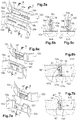
- the anchoring structure 10 further comprises a plurality of protective tabs 16 connecting juxtaposed assembly portions 121, 122 of adjacent strips.
- Each protective tab 16 is secured to an assembly portion 122 of a strip 12 by a longitudinal junction line 18 and extends in the direction of the juxtaposed assembly portion 121, at least up to the latter.
- each protective tab could be secured to an assembly portion 121 and extend in the direction of an assembly portion 122, or else protective tabs could be provided alternately on the portions 121 and 122 of the same strip.
- each protective tab 16 extends to the juxtaposed assembly portion 121 and beyond it (see figure 3 ).
- Each protective tab 16 crosses then an orifice 20 of substantially corresponding shape formed in the assembly portion 121 of the adjacent strip (see figure 3 ).
- the protective tabs 16 are further inclined towards the lower longitudinal edge 12b.
- the protective tabs 16 are here formed by cutting the assembly portion 122 from which they originate, and are therefore folded relative to this assembly portion 122 along the junction line 18.
- Each protective tab 16 is thus inclined relative to the planes of the assembly portions 121, 122 (see figure 3 ).
- each protective tab 16 defines a plane intersecting the planes of the assembly portions 121, 122.
- the fixing lugs 16 thus extend through the space 19 separating two juxtaposed assembly portions 121, 122 ( fig. 3 ), thus limiting the diffusion of chemical species from the upper longitudinal edge 12a of the bands 12 between the portions 121, 122.
- the invention is not however limited to this particular embodiment.
- a protective tab 16 'could extend from the side of the upper longitudinal edge 12a as far as the juxtaposed assembly portion 121 and be in abutment against the latter, thus closing the space 19 separating the assembly portions 121 122 on the side opposite the lower longitudinal edge 12b.
- the protective tab 16 'then substantially forms a right angle with the planes of the assembly portions 121, 122.
- each protective tab 16a, 16b is provided on the same assembly portion 122, each connected to the assembly portion 122 by a longitudinal junction line 18a, 18b respectively.
- each protective tab 16a, 16b is formed of a part of the assembly portion 122 folded along the junction line 18a, 18b respectively, in the direction of the juxtaposed assembly portion 121. They can for example be formed by cutting or stamping. It will be noted that one of the fixing lugs 16a is inclined towards the upper longitudinal edge 12a (see figure 5b ) while the other fixing lug 16b is inclined towards the lower longitudinal edge 12b.
- Each of the fixing lugs 16a, 16b is inserted into a corresponding orifice 20a, 20b respectively, formed in the juxtaposed assembly portion 121.
- the protective tabs 16a, 16b also ensure the assembly of the assembly portions 121, 122, their opposite orientation favoring this assembly. It will be noted that the protective tabs 16a, 16b are of the same dimensions and located one next to the other, the respective junction lines 18a, 18b being offset perpendicularly to the direction L, as well as the orifices 20a, 20b.
- a protective tab 16 "of an assembly portion 122 is also formed of a part of the assembly portion folded back along the junction line 18 towards the juxtaposed assembly portion 121, but this part extends to the upper longitudinal edge 12a.
- the folded protective tab 16 "then passes through the corresponding orifice 20 of the adjacent assembly portion.
- a 16 "protective tab identical to that shown on the figures 6a, 6b is carried out. Instead of passing through an orifice 20 of the adjacent assembly portion 121, it passes over a recess 20 "(see figure 7b ), which is located at a distance from the lower longitudinal edge 12b and extends to the upper longitudinal edge 12a of the strip.
- the composite material 2 entirely covers the assembly portion 122 comprising the protective tab 16 "in the embodiments of figures 6b and 7b .
- the protective tabs 16, 16 can nevertheless participate in the fixing of the assembly portions.
- one end 16 "a of the protective tab 16 opposite its junction line 18 (forming the upper longitudinal edge 12a before folding of the fixing tab 16") is folded in the direction of a face 121a of the juxtaposed assembly portion 121 opposite to the face 121b located opposite the assembly portion 122 integral with the protective tab 16 ". It may then be advantageous for the surface of the protective tabs 16, 16" to be greater than the port surface 20.
- the means for fixing the strips 12 comprise two tabs 22 per second portion 122 formed by cutting in these second portions 122. These tabs 22 are connected to the second portion 122 by a junction line perpendicular to the upper longitudinal edges. 12a and lower 12b. They are here oriented towards each other (see figure 1 ). These tongues 22 are received in corresponding orifices 24 of the first portions 121.
- the fixing of the bands 12 is thus carried out very simply by inserting the tongues 22 of the second portions 122 into the corresponding orifices 24 of the first portions 121, then by folding back the tongues 22. against these first portions 121 on their face opposite to the face juxtaposed to the second portion 122 (see figure 1 ).
- a single tongue 22 could be provided per second portion 122.
- the tongues 22 and the orifices 24 can be arranged indifferently on the first or second portions of strip 121, 122.
- the tongues 22 are here provided on the same assembly portions 122 as the protective tabs 16, the orifices 24 being made on the assembly portions 121 comprising the orifices 20 or the recesses 20 "for receiving the protective tabs 16, 16" .
- each strip 12 may also have tabs of material 26 cut from at least one portion other than an assembly portion (here is a portion 123) and folded so as to project from this portion along a fold line perpendicular to the longitudinal direction of the web.
- Such a configuration can improve the anchoring of the material. composite on the anchoring element, the tongue 26 then being embedded in the composite material, the retention of which is also reinforced by virtue of the fact that it passes through the cutting orifice 28 released by the folded tongue 26.
- the tongues 26 of material originating from portions forming part of the same cell can be folded towards one another. This arrangement makes it possible to obtain two tabs folded towards the center of each cell when the strips are assembled together.
- tongues 26 can also be bent so as to extend substantially parallel to the planes of the assembly portions 121, 122 of the strips.
- the figures 8-10 show an anchoring structure 10 ', the shape of which differs from the embodiment shown in the figures 1-3 only by the shape of the upper longitudinal edges 12'a of the bands 12 'and the position of the tongues 26'. These tongues 26 are arranged at different distances from the lower longitudinal edge 12b from one portion 123 to another (see figure 9 ).
- the other elements represented fig. 8-10 are identical to those described with reference to figures 1-3 and are designated by the same reference numerals.
- the upper longitudinal edge 12'a of each assembly portion 122 carrying the protective tab 16 extends parallel to the lower longitudinal edge 12b, in the extension of the junction line 18 of the protective tab. 16.
- the upper longitudinal edge 12'a extends at a distance h from the lower longitudinal edge 12b less than the distance H separating the upper longitudinal edge 12'a from the strip portions. adjacent 123 (see fig.9 ).
- the upper longitudinal edge 12'a of the same strip does not extend in a single and unique plane before shaping of the anchoring structure.
- the upper longitudinal edge 12'a extends at the distance h from the lower longitudinal edge 12b over the entire length of the assembly portion 122 as well as over part of the length of the adjacent strip portions. 123.
- the composite material 2 can completely cover the upper longitudinal edge 12'a of height h, creating an additional barrier to the diffusion of gas between the juxtaposed assembly portions 121, 122.
- weld seams 30, 32 extending along the edges of the juxtaposed assembly portions 121, 122 perpendicular to the longitudinal direction of a strip 12 '.
- these weld beads extend perpendicularly to the longitudinal direction of a strip 12 'and at least partially close the access to the space separating the juxtaposed assembly portions 121, 122 further reducing the risks of diffusion. of gas between these portions.
- These weld beads can of course also be provided in the embodiment described with reference to figures 1-3 , whatever the shape and number of protective legs.
- the anchoring structure 10 shown figure 1 can be shaped before it is fixed to the metal wall 1, for example by rolling in order to match the shape of this metal wall.
- the honeycomb structure of the present invention is advantageously made of stainless steel (stainless steel contains at most 1.2% by weight of carbon and at least 10.5% by weight of chromium according to the EN10008 standard).
- stainless steel will be chosen so as to withstand the environment of the enclosure in which the anchoring structure is to be used.
- the composite material is preferably a material resulting from an assembly of at least two immiscible materials having a high adhesion capacity.
- the composite material is a composite construction material such as concrete, in particular concrete suitable for use in a fluid catalytic cracking unit.
Landscapes
- Chemical & Material Sciences (AREA)
- Engineering & Computer Science (AREA)
- Organic Chemistry (AREA)
- Chemical Kinetics & Catalysis (AREA)
- Oil, Petroleum & Natural Gas (AREA)
- General Engineering & Computer Science (AREA)
- General Chemical & Material Sciences (AREA)
- Mechanical Engineering (AREA)
- Combustion & Propulsion (AREA)
- Catalysts (AREA)
- Production Of Liquid Hydrocarbon Mixture For Refining Petroleum (AREA)
- Connection Of Plates (AREA)
- Devices Affording Protection Of Roads Or Walls For Sound Insulation (AREA)
- Laminated Bodies (AREA)
- Furnace Housings, Linings, Walls, And Ceilings (AREA)
- Bridges Or Land Bridges (AREA)
Claims (16)
- Metallische Wabenverankerungsstruktur (10, 10'), wobei die Verankerungsstruktur (10, 10') aus einer Vielzahl von Streifen (12, 12') gebildet ist, die paarweise derart montiert sind, dass eine Vielzahl von Zellen (14) zwischen zwei benachbarten Streifen definieren ist, wobei jeder Streifen (12) entlang seiner Länge in eine Vielzahl von Abschnitten unterteilt ist, darunter mindestens eine Reihe flacher Montageabschnitte (121, 122), die nebeneinanderliegen und von Befestigungsmitteln an eine Reihe von Montageabschnitten eines angrenzenden Streifens montiert sind, wobei jeder Streifen (12) eine untere Längskante (12b) aufweist, die dazu bestimmt ist, gegen eine Wand, die zu schützen ist, angelegt zu werden, und eine obere Längskante (12a, 12'a), die der unteren Längskante entgegengesetzt ist,
dadurch gekennzeichnet, dass sie außerdem eine Vielzahl von Schutzlaschen (16, 16', 16", 16a, 16b) umfasst, die jedes Paar nebeneinanderliegender Montageabschnitte (121, 122) verbinden, wobei jede Schutzlasche (16, 16', 16", 16a, 16b) an einem Montageabschnitt (122) durch eine Längsverbindungslinie (18) fest verbunden ist, und sich jede Schutzlasche (16, 16', 16", 16a, 16b) in Richtung des danebenliegenden Montageabschnitts (121), mindestens bis zu diesem erstreckt. - Verankerungsstruktur (10, 10') nach Anspruch 1, dadurch gekennzeichnet, dass eine einzige Schutzlasche (16, 16', 16") zwei nebeneinanderliegende Montageabschnitte verbindet.
- Verankerungsstruktur (10, 10') nach Anspruch 1, dadurch gekennzeichnet, dass mindestens zwei Schutzlaschen (16a, 16b) zwei nebeneinanderliegende Montageabschnitte verbinden.
- Verankerungsstruktur (10, 10') nach einem der Ansprüche 1 bis 3, dadurch gekennzeichnet, dass jedes Paar nebeneinanderliegender Montageabschnitte (121, 122) eine oder mehrere Schutzlaschen aufweist, die sich über mindestens 50 % der Länge der Montageabschnitte erstrecken.
- Verankerungsstruktur (10, 10') nach einem der Ansprüche 1 bis 4, dadurch gekennzeichnet, dass jede Schutzlasche (16, 16', 16", 16a, 16b) aus einem Teil des Montageabschnitts (122), der entlang der Verbindungslinie (18) in Richtung des danebenliegenden Montageabschnitts (121) zurückgebogen ist, gebildet ist.
- Verankerungsstruktur (10, 10') nach Anspruch 5, dadurch gekennzeichnet, dass jede Schutzlasche (16") aus einem Teil des Montageabschnitts, der sich bis zu der oberen Längskante dieses erstreckt, gebildet ist.
- Verankerungsstruktur (10') nach Anspruch 6, dadurch gekennzeichnet, dass sich die obere Längskante (12'a) jedes Montageabschnitts (122), der die mindestens eine Schutzlasche (16) trägt, parallel zu der unteren Längskante (12b), in der Verlängerung der Verbindungslinie (18) der mindestens einen Schutzlasche (16) erstreckt.
- Verankerungsstruktur (10') nach Anspruch 7, dadurch gekennzeichnet, dass sich die obere Längskante (12'a) von Streifenabschnitten (123), die an einen Montageabschnitt (122), der die mindestens eine Schutzlasche (16) trägt, an Grenzen, parallel zu der unteren Längskante (12b) in der Verlängerung der Verbindungslinie (18) in unmittelbarer Nähe des Montageabschnitts (122) erstreckt.
- Verankerungsstruktur (10) nach einem der Ansprüche 1 bis 8, dadurch gekennzeichnet, dass sich jede Schutzlasche (16, 16", 16a, 16b) bis zu dem danebenliegenden Montageabschnitt (121) und über diesen hinaus erstreckt, und dass dieser danebenliegende Montageabschnitt (121) eine Aussparung (20, 20, 20a, 20b, 20") für den Durchgang jeder Schutzlasche aufweist.
- Verankerungsstruktur (10) nach Anspruch 9, dadurch gekennzeichnet, dass die Aussparung in einem Abstand von der unteren Längskante liegt und sich bis zu der oberen Längskante oder bis zu einem vorbestimmten Abstand von der oberen Längskante erstreckt.
- Verankerungsstruktur (10) nach einem der Ansprüche 9 oder 10, dadurch gekennzeichnet, dass ein Ende (16"a) jeder Schutzlasche (16") gegenüber ihrer Verbindungslinie (18) in Richtung einer Fläche (121a) des danebenliegenden Montageabschnitts (121) gegenüber der Fläche (121b), die dem Montageabschnitt (122) zugewandt liegt, der fest mit der Schutzlasche (16"a) verbunden ist, zurückgebogen ist.
- Verankerungsstruktur (10) nach einem der Ansprüche 1 bis 11, dadurch gekennzeichnet, dass die Schutzlaschen (16") die Befestigungsmittel der Montageabschnitte bilden.
- Verankerungsstruktur (10) nach einem der Ansprüche 1 bis 12, dadurch gekennzeichnet, dass die Montageabschnitte Befestigungsmittel aufweisen, die von den Schutzlaschen getrennt sind, wobei diese zwischen den Befestigungsmitteln und der oberen Längskante eines Montageabschnitts liegen.
- Verankerungsstruktur (10) nach einem der Ansprüche 1 bis 13, dadurch gekennzeichnet, dass die nebeneinanderliegenden Montageabschnitte (121, 122) durch mindestens eine Schweißnaht (30, 32) entlang ihrer Kanten senkrecht zu der Längsrichtung eines Streifens montiert sind.
- Erosionsschutzbeschichtung, dadurch gekennzeichnet, dass sie eine Verankerungsstruktur (10) nach einem der Ansprüche 1 bis 14 umfasst, die in ein Verbundmaterial (2), beispielsweise Beton, eingebettet ist, wobei das Verbundmaterial jede Zelle (14) von der unteren Längskante (12b) jedes Streifens (12) mindestens bis zu der oberen Längskante (12a) füllt.
- Einschluss einer katalytischen Fluidcrackanlage, dadurch gekennzeichnet, dass er mindestens eine Innen- oder Außenwand (1) umfasst, die mit mindestens einer Beschichtung nach Anspruch 15 beschichtet ist, wobei die untere Längskante (12b) jedes Streifens (12) der Verankerungsstruktur (10) der Beschichtung durch Schweißen auf der Innen- oder Außenwand (1) des Gehäuses befestigt ist.
Applications Claiming Priority (2)
| Application Number | Priority Date | Filing Date | Title |
|---|---|---|---|
| FR1752493A FR3064207B1 (fr) | 2017-03-24 | 2017-03-24 | Structure d'ancrage pour un revetement anti erosion, notamment de protection d'une paroi d'unite fcc. |
| PCT/EP2018/057346 WO2018172478A1 (fr) | 2017-03-24 | 2018-03-22 | Structure d'ancrage pour un revetement anti erosion, notamment de protection d'une paroi d'unite fcc |
Publications (2)
| Publication Number | Publication Date |
|---|---|
| EP3600645A1 EP3600645A1 (de) | 2020-02-05 |
| EP3600645B1 true EP3600645B1 (de) | 2021-07-14 |
Family
ID=58993069
Family Applications (1)
| Application Number | Title | Priority Date | Filing Date |
|---|---|---|---|
| EP18719056.6A Active EP3600645B1 (de) | 2017-03-24 | 2018-03-22 | Verankerungsstruktur für eine erosionsschutzbeschichtung, insbesondere zum schutz einer wand einer fcc-einheit |
Country Status (9)
| Country | Link |
|---|---|
| US (1) | US10799846B2 (de) |
| EP (1) | EP3600645B1 (de) |
| JP (1) | JP2020514137A (de) |
| KR (1) | KR20190132654A (de) |
| CN (1) | CN110650795A (de) |
| ES (1) | ES2884775T3 (de) |
| FR (1) | FR3064207B1 (de) |
| RU (1) | RU2019133345A (de) |
| WO (1) | WO2018172478A1 (de) |
Families Citing this family (6)
| Publication number | Priority date | Publication date | Assignee | Title |
|---|---|---|---|---|
| US10857616B2 (en) * | 2017-06-02 | 2020-12-08 | Jt Thorpe & Sons, Inc. | Refractory anchor system |
| US12305925B2 (en) | 2018-08-08 | 2025-05-20 | Brand Shared Services, Llc | Refractory anchor device and system |
| US12018511B2 (en) | 2021-03-08 | 2024-06-25 | Brand Shared Services, Llc | X-shaped refractory anchor device and system |
| NL2023011B1 (en) * | 2019-04-26 | 2020-11-02 | Silicon Refractory Anchoring Systems B V | A refractory anchor |
| USD962757S1 (en) * | 2021-10-14 | 2022-09-06 | Silicon Holding B.V. | Refractory anchor |
| WO2024086732A1 (en) * | 2022-10-19 | 2024-04-25 | Brand Shared Services, Llc | Refractory anchor device and system |
Family Cites Families (6)
| Publication number | Priority date | Publication date | Assignee | Title |
|---|---|---|---|---|
| US3033086A (en) * | 1957-04-17 | 1962-05-08 | Causeway Reinforcement Ltd | Reinforcement for mastics, mortar and the like |
| IT1175888B (it) * | 1984-10-22 | 1987-07-15 | Costacurta Vico Spa | Grigliato perfezionato a nido d'ape per l'armatura di gettate refrattarie monolitiche per impianti petrol-chimici, camini, reattori-cicloni e simili |
| US9662627B2 (en) * | 2011-10-28 | 2017-05-30 | Uop Llc | Riser reactor with flow disruptors |
| FR2993201B1 (fr) * | 2012-07-10 | 2014-08-08 | Total Raffinage Marketing | Procede de realisation d'un revetement anti erosion sur une paroi interne d'une enceinte d'unite fcc et structure d'ancrage pour la realisation de ce revetement. |
| US10047298B2 (en) * | 2014-03-12 | 2018-08-14 | Exxonmobil Research And Engineering Company | Internal lining for delayed coker drum |
| FR3028307B1 (fr) * | 2014-11-07 | 2021-05-21 | Total Raffinage Chimie | Element d'ancrage d'un revetement anti erosion sur une paroi interne d'une enceinte d'unite fcc. |
-
2017
- 2017-03-24 FR FR1752493A patent/FR3064207B1/fr not_active Expired - Fee Related
-
2018
- 2018-03-22 CN CN201880033488.4A patent/CN110650795A/zh active Pending
- 2018-03-22 WO PCT/EP2018/057346 patent/WO2018172478A1/fr not_active Ceased
- 2018-03-22 ES ES18719056T patent/ES2884775T3/es active Active
- 2018-03-22 JP JP2019552072A patent/JP2020514137A/ja active Pending
- 2018-03-22 US US16/496,850 patent/US10799846B2/en not_active Expired - Fee Related
- 2018-03-22 KR KR1020197029881A patent/KR20190132654A/ko not_active Withdrawn
- 2018-03-22 EP EP18719056.6A patent/EP3600645B1/de active Active
- 2018-03-22 RU RU2019133345A patent/RU2019133345A/ru unknown
Also Published As
| Publication number | Publication date |
|---|---|
| WO2018172478A1 (fr) | 2018-09-27 |
| FR3064207B1 (fr) | 2019-04-19 |
| US10799846B2 (en) | 2020-10-13 |
| CN110650795A (zh) | 2020-01-03 |
| JP2020514137A (ja) | 2020-05-21 |
| FR3064207A1 (fr) | 2018-09-28 |
| EP3600645A1 (de) | 2020-02-05 |
| KR20190132654A (ko) | 2019-11-28 |
| RU2019133345A (ru) | 2021-04-26 |
| ES2884775T3 (es) | 2021-12-13 |
| US20200078762A1 (en) | 2020-03-12 |
Similar Documents
| Publication | Publication Date | Title |
|---|---|---|
| EP3600645B1 (de) | Verankerungsstruktur für eine erosionsschutzbeschichtung, insbesondere zum schutz einer wand einer fcc-einheit | |
| EP2872317B1 (de) | Verfahren zur herstellung einer erosionsschutzbeschichtung auf der innenwand einer verbrennungskammer einer fcc-anlage und verankerungsstruktur zur herstellung dieser beschichtung | |
| FR3028307A1 (fr) | Element d'ancrage d'un revetement anti erosion sur une paroi interne d'une enceinte d'unite fcc. | |
| CA2665306C (fr) | Structure cylindrique composee d'elements rectangulaires | |
| WO2016170254A1 (fr) | Cuve etanche et thermiquement isolante equipee d'un element traversant | |
| EP1818617B1 (de) | Querwand einer Brennkammer, die mit Multiperforationslöchern ausgestattet ist | |
| EP3425261B1 (de) | Dichter und wärmeisolierter tank | |
| FR3004508A1 (fr) | Bloc isolant pour la fabrication d'une paroi de cuve etanche et isolante | |
| EP2384809A1 (de) | Herausnehmbare Körbe, die Filterpartikel für einen Festbettreaktor enthalten | |
| EP2003417B1 (de) | Haltestruktur für Raketenbehälter einer vertikalen Raketenabschussvorrichtung | |
| WO2014170572A1 (fr) | Cuve étanche et thermiquement isolante | |
| EP4226075A1 (de) | Abgedichteter und wärmeisolierender tank | |
| FR3111410A1 (fr) | Dôme liquide d’une cuve de stockage pour gaz liquéfié | |
| WO2018172481A1 (fr) | Structure d'ancrage depourvue de parties assemblees juxtaposees pour un revetement anti erosion, notamment de protection d'une paroi d'unite fcc | |
| EP2895263A1 (de) | Strukturierte hochleistungsverkapselung für eine flüssigkeitskontaktsäule | |
| FR3042988A1 (fr) | Procede de pose d'un revetement anti erosion sur une paroi d'un equipement d'unite fcc | |
| FR3112764A1 (fr) | Système d’empilement de membranes d’une cuve étanche et thermiquement isolante | |
| CA1252672A (fr) | Paroi de foyer comportant des buses d'alimentation moulees en deux parties complementaires | |
| EP2671665A1 (de) | Schutzelement für ein Fahrzeug, Fahrzeug versehen mit einem solchen Element und Verfahren zum Herstellen | |
| FR3063916A1 (fr) | Structure d'ancrage formee d'une unique tole decoupee pour un revetement anti erosion, notamment de protection d'une paroi d'unite de craquage catalytique fluide. | |
| FR2669229A1 (fr) | Materiau pour arreter la propagation des flammes et dispositifs pour la mise en óoeuvre de ce materiau. | |
| FR3143711A1 (fr) | Cuve étanche et thermiquement isolante comportant un élément traversant | |
| FR3131361A1 (fr) | Cuve comprenant une membrane étanche présentant des traversées | |
| FR3152568A1 (fr) | Cuve étanche et thermiquement isolante | |
| FR3161936A1 (fr) | Procédé d’installation d’une membrane d’étanchéité d’une paroi de cuve, et outil de positionnement correspondant |
Legal Events
| Date | Code | Title | Description |
|---|---|---|---|
| STAA | Information on the status of an ep patent application or granted ep patent |
Free format text: STATUS: UNKNOWN |
|
| STAA | Information on the status of an ep patent application or granted ep patent |
Free format text: STATUS: THE INTERNATIONAL PUBLICATION HAS BEEN MADE |
|
| PUAI | Public reference made under article 153(3) epc to a published international application that has entered the european phase |
Free format text: ORIGINAL CODE: 0009012 |
|
| STAA | Information on the status of an ep patent application or granted ep patent |
Free format text: STATUS: REQUEST FOR EXAMINATION WAS MADE |
|
| 17P | Request for examination filed |
Effective date: 20190923 |
|
| AK | Designated contracting states |
Kind code of ref document: A1 Designated state(s): AL AT BE BG CH CY CZ DE DK EE ES FI FR GB GR HR HU IE IS IT LI LT LU LV MC MK MT NL NO PL PT RO RS SE SI SK SM TR |
|
| AX | Request for extension of the european patent |
Extension state: BA ME |
|
| DAV | Request for validation of the european patent (deleted) | ||
| DAX | Request for extension of the european patent (deleted) | ||
| GRAP | Despatch of communication of intention to grant a patent |
Free format text: ORIGINAL CODE: EPIDOSNIGR1 |
|
| STAA | Information on the status of an ep patent application or granted ep patent |
Free format text: STATUS: GRANT OF PATENT IS INTENDED |
|
| INTG | Intention to grant announced |
Effective date: 20210203 |
|
| GRAS | Grant fee paid |
Free format text: ORIGINAL CODE: EPIDOSNIGR3 |
|
| GRAA | (expected) grant |
Free format text: ORIGINAL CODE: 0009210 |
|
| STAA | Information on the status of an ep patent application or granted ep patent |
Free format text: STATUS: THE PATENT HAS BEEN GRANTED |
|
| AK | Designated contracting states |
Kind code of ref document: B1 Designated state(s): AL AT BE BG CH CY CZ DE DK EE ES FI FR GB GR HR HU IE IS IT LI LT LU LV MC MK MT NL NO PL PT RO RS SE SI SK SM TR |
|
| REG | Reference to a national code |
Ref country code: GB Ref legal event code: FG4D Free format text: NOT ENGLISH |
|
| REG | Reference to a national code |
Ref country code: DE Ref legal event code: R096 Ref document number: 602018020094 Country of ref document: DE |
|
| REG | Reference to a national code |
Ref country code: IE Ref legal event code: FG4D Free format text: LANGUAGE OF EP DOCUMENT: FRENCH |
|
| REG | Reference to a national code |
Ref country code: AT Ref legal event code: REF Ref document number: 1410223 Country of ref document: AT Kind code of ref document: T Effective date: 20210815 |
|
| REG | Reference to a national code |
Ref country code: NL Ref legal event code: FP |
|
| REG | Reference to a national code |
Ref country code: LT Ref legal event code: MG9D |
|
| REG | Reference to a national code |
Ref country code: ES Ref legal event code: FG2A Ref document number: 2884775 Country of ref document: ES Kind code of ref document: T3 Effective date: 20211213 |
|
| REG | Reference to a national code |
Ref country code: AT Ref legal event code: MK05 Ref document number: 1410223 Country of ref document: AT Kind code of ref document: T Effective date: 20210714 |
|
| PG25 | Lapsed in a contracting state [announced via postgrant information from national office to epo] |
Ref country code: RS Free format text: LAPSE BECAUSE OF FAILURE TO SUBMIT A TRANSLATION OF THE DESCRIPTION OR TO PAY THE FEE WITHIN THE PRESCRIBED TIME-LIMIT Effective date: 20210714 Ref country code: SE Free format text: LAPSE BECAUSE OF FAILURE TO SUBMIT A TRANSLATION OF THE DESCRIPTION OR TO PAY THE FEE WITHIN THE PRESCRIBED TIME-LIMIT Effective date: 20210714 Ref country code: HR Free format text: LAPSE BECAUSE OF FAILURE TO SUBMIT A TRANSLATION OF THE DESCRIPTION OR TO PAY THE FEE WITHIN THE PRESCRIBED TIME-LIMIT Effective date: 20210714 Ref country code: FI Free format text: LAPSE BECAUSE OF FAILURE TO SUBMIT A TRANSLATION OF THE DESCRIPTION OR TO PAY THE FEE WITHIN THE PRESCRIBED TIME-LIMIT Effective date: 20210714 Ref country code: NO Free format text: LAPSE BECAUSE OF FAILURE TO SUBMIT A TRANSLATION OF THE DESCRIPTION OR TO PAY THE FEE WITHIN THE PRESCRIBED TIME-LIMIT Effective date: 20211014 Ref country code: PT Free format text: LAPSE BECAUSE OF FAILURE TO SUBMIT A TRANSLATION OF THE DESCRIPTION OR TO PAY THE FEE WITHIN THE PRESCRIBED TIME-LIMIT Effective date: 20211115 Ref country code: LT Free format text: LAPSE BECAUSE OF FAILURE TO SUBMIT A TRANSLATION OF THE DESCRIPTION OR TO PAY THE FEE WITHIN THE PRESCRIBED TIME-LIMIT Effective date: 20210714 Ref country code: BG Free format text: LAPSE BECAUSE OF FAILURE TO SUBMIT A TRANSLATION OF THE DESCRIPTION OR TO PAY THE FEE WITHIN THE PRESCRIBED TIME-LIMIT Effective date: 20211014 Ref country code: AT Free format text: LAPSE BECAUSE OF FAILURE TO SUBMIT A TRANSLATION OF THE DESCRIPTION OR TO PAY THE FEE WITHIN THE PRESCRIBED TIME-LIMIT Effective date: 20210714 |
|
| PG25 | Lapsed in a contracting state [announced via postgrant information from national office to epo] |
Ref country code: PL Free format text: LAPSE BECAUSE OF FAILURE TO SUBMIT A TRANSLATION OF THE DESCRIPTION OR TO PAY THE FEE WITHIN THE PRESCRIBED TIME-LIMIT Effective date: 20210714 Ref country code: LV Free format text: LAPSE BECAUSE OF FAILURE TO SUBMIT A TRANSLATION OF THE DESCRIPTION OR TO PAY THE FEE WITHIN THE PRESCRIBED TIME-LIMIT Effective date: 20210714 Ref country code: GR Free format text: LAPSE BECAUSE OF FAILURE TO SUBMIT A TRANSLATION OF THE DESCRIPTION OR TO PAY THE FEE WITHIN THE PRESCRIBED TIME-LIMIT Effective date: 20211015 |
|
| REG | Reference to a national code |
Ref country code: DE Ref legal event code: R097 Ref document number: 602018020094 Country of ref document: DE |
|
| PG25 | Lapsed in a contracting state [announced via postgrant information from national office to epo] |
Ref country code: DK Free format text: LAPSE BECAUSE OF FAILURE TO SUBMIT A TRANSLATION OF THE DESCRIPTION OR TO PAY THE FEE WITHIN THE PRESCRIBED TIME-LIMIT Effective date: 20210714 |
|
| PLBE | No opposition filed within time limit |
Free format text: ORIGINAL CODE: 0009261 |
|
| STAA | Information on the status of an ep patent application or granted ep patent |
Free format text: STATUS: NO OPPOSITION FILED WITHIN TIME LIMIT |
|
| PG25 | Lapsed in a contracting state [announced via postgrant information from national office to epo] |
Ref country code: SM Free format text: LAPSE BECAUSE OF FAILURE TO SUBMIT A TRANSLATION OF THE DESCRIPTION OR TO PAY THE FEE WITHIN THE PRESCRIBED TIME-LIMIT Effective date: 20210714 Ref country code: SK Free format text: LAPSE BECAUSE OF FAILURE TO SUBMIT A TRANSLATION OF THE DESCRIPTION OR TO PAY THE FEE WITHIN THE PRESCRIBED TIME-LIMIT Effective date: 20210714 Ref country code: RO Free format text: LAPSE BECAUSE OF FAILURE TO SUBMIT A TRANSLATION OF THE DESCRIPTION OR TO PAY THE FEE WITHIN THE PRESCRIBED TIME-LIMIT Effective date: 20210714 Ref country code: EE Free format text: LAPSE BECAUSE OF FAILURE TO SUBMIT A TRANSLATION OF THE DESCRIPTION OR TO PAY THE FEE WITHIN THE PRESCRIBED TIME-LIMIT Effective date: 20210714 Ref country code: CZ Free format text: LAPSE BECAUSE OF FAILURE TO SUBMIT A TRANSLATION OF THE DESCRIPTION OR TO PAY THE FEE WITHIN THE PRESCRIBED TIME-LIMIT Effective date: 20210714 Ref country code: AL Free format text: LAPSE BECAUSE OF FAILURE TO SUBMIT A TRANSLATION OF THE DESCRIPTION OR TO PAY THE FEE WITHIN THE PRESCRIBED TIME-LIMIT Effective date: 20210714 |
|
| 26N | No opposition filed |
Effective date: 20220419 |
|
| PG25 | Lapsed in a contracting state [announced via postgrant information from national office to epo] |
Ref country code: MC Free format text: LAPSE BECAUSE OF FAILURE TO SUBMIT A TRANSLATION OF THE DESCRIPTION OR TO PAY THE FEE WITHIN THE PRESCRIBED TIME-LIMIT Effective date: 20210714 |
|
| REG | Reference to a national code |
Ref country code: CH Ref legal event code: PL |
|
| PG25 | Lapsed in a contracting state [announced via postgrant information from national office to epo] |
Ref country code: LU Free format text: LAPSE BECAUSE OF NON-PAYMENT OF DUE FEES Effective date: 20220322 Ref country code: LI Free format text: LAPSE BECAUSE OF NON-PAYMENT OF DUE FEES Effective date: 20220331 Ref country code: IE Free format text: LAPSE BECAUSE OF NON-PAYMENT OF DUE FEES Effective date: 20220322 Ref country code: CH Free format text: LAPSE BECAUSE OF NON-PAYMENT OF DUE FEES Effective date: 20220331 |
|
| PGFP | Annual fee paid to national office [announced via postgrant information from national office to epo] |
Ref country code: FR Payment date: 20230327 Year of fee payment: 6 |
|
| PGFP | Annual fee paid to national office [announced via postgrant information from national office to epo] |
Ref country code: IT Payment date: 20230328 Year of fee payment: 6 Ref country code: GB Payment date: 20230322 Year of fee payment: 6 Ref country code: DE Payment date: 20230321 Year of fee payment: 6 Ref country code: BE Payment date: 20230321 Year of fee payment: 6 |
|
| PGFP | Annual fee paid to national office [announced via postgrant information from national office to epo] |
Ref country code: NL Payment date: 20230321 Year of fee payment: 6 |
|
| PGFP | Annual fee paid to national office [announced via postgrant information from national office to epo] |
Ref country code: ES Payment date: 20230529 Year of fee payment: 6 |
|
| PG25 | Lapsed in a contracting state [announced via postgrant information from national office to epo] |
Ref country code: MK Free format text: LAPSE BECAUSE OF FAILURE TO SUBMIT A TRANSLATION OF THE DESCRIPTION OR TO PAY THE FEE WITHIN THE PRESCRIBED TIME-LIMIT Effective date: 20210714 Ref country code: CY Free format text: LAPSE BECAUSE OF FAILURE TO SUBMIT A TRANSLATION OF THE DESCRIPTION OR TO PAY THE FEE WITHIN THE PRESCRIBED TIME-LIMIT Effective date: 20210714 |
|
| PG25 | Lapsed in a contracting state [announced via postgrant information from national office to epo] |
Ref country code: HU Free format text: LAPSE BECAUSE OF FAILURE TO SUBMIT A TRANSLATION OF THE DESCRIPTION OR TO PAY THE FEE WITHIN THE PRESCRIBED TIME-LIMIT; INVALID AB INITIO Effective date: 20180322 |
|
| PG25 | Lapsed in a contracting state [announced via postgrant information from national office to epo] |
Ref country code: TR Free format text: LAPSE BECAUSE OF FAILURE TO SUBMIT A TRANSLATION OF THE DESCRIPTION OR TO PAY THE FEE WITHIN THE PRESCRIBED TIME-LIMIT Effective date: 20210714 |
|
| PG25 | Lapsed in a contracting state [announced via postgrant information from national office to epo] |
Ref country code: MT Free format text: LAPSE BECAUSE OF FAILURE TO SUBMIT A TRANSLATION OF THE DESCRIPTION OR TO PAY THE FEE WITHIN THE PRESCRIBED TIME-LIMIT Effective date: 20210714 |
|
| REG | Reference to a national code |
Ref country code: DE Ref legal event code: R119 Ref document number: 602018020094 Country of ref document: DE |
|
| REG | Reference to a national code |
Ref country code: NL Ref legal event code: MM Effective date: 20240401 |
|
| GBPC | Gb: european patent ceased through non-payment of renewal fee |
Effective date: 20240322 |
|
| PG25 | Lapsed in a contracting state [announced via postgrant information from national office to epo] |
Ref country code: NL Free format text: LAPSE BECAUSE OF NON-PAYMENT OF DUE FEES Effective date: 20240401 |
|
| REG | Reference to a national code |
Ref country code: BE Ref legal event code: MM Effective date: 20240331 |
|
| PG25 | Lapsed in a contracting state [announced via postgrant information from national office to epo] |
Ref country code: NL Free format text: LAPSE BECAUSE OF NON-PAYMENT OF DUE FEES Effective date: 20240401 |
|
| PG25 | Lapsed in a contracting state [announced via postgrant information from national office to epo] |
Ref country code: DE Free format text: LAPSE BECAUSE OF NON-PAYMENT OF DUE FEES Effective date: 20241001 |
|
| PG25 | Lapsed in a contracting state [announced via postgrant information from national office to epo] |
Ref country code: BE Free format text: LAPSE BECAUSE OF NON-PAYMENT OF DUE FEES Effective date: 20240331 |
|
| PG25 | Lapsed in a contracting state [announced via postgrant information from national office to epo] |
Ref country code: GB Free format text: LAPSE BECAUSE OF NON-PAYMENT OF DUE FEES Effective date: 20240322 |
|
| PG25 | Lapsed in a contracting state [announced via postgrant information from national office to epo] |
Ref country code: FR Free format text: LAPSE BECAUSE OF NON-PAYMENT OF DUE FEES Effective date: 20240331 |
|
| PG25 | Lapsed in a contracting state [announced via postgrant information from national office to epo] |
Ref country code: GB Free format text: LAPSE BECAUSE OF NON-PAYMENT OF DUE FEES Effective date: 20240322 Ref country code: FR Free format text: LAPSE BECAUSE OF NON-PAYMENT OF DUE FEES Effective date: 20240331 Ref country code: DE Free format text: LAPSE BECAUSE OF NON-PAYMENT OF DUE FEES Effective date: 20241001 Ref country code: BE Free format text: LAPSE BECAUSE OF NON-PAYMENT OF DUE FEES Effective date: 20240331 |
|
| PG25 | Lapsed in a contracting state [announced via postgrant information from national office to epo] |
Ref country code: IT Free format text: LAPSE BECAUSE OF NON-PAYMENT OF DUE FEES Effective date: 20240322 |
|
| PG25 | Lapsed in a contracting state [announced via postgrant information from national office to epo] |
Ref country code: ES Free format text: LAPSE BECAUSE OF NON-PAYMENT OF DUE FEES Effective date: 20240323 |