EP3600743B1 - Procédé combiné de chanfreinage par décolletage en développante et de limage d'une pièce - Google Patents
Procédé combiné de chanfreinage par décolletage en développante et de limage d'une pièce Download PDFInfo
- Publication number
- EP3600743B1 EP3600743B1 EP18713867.2A EP18713867A EP3600743B1 EP 3600743 B1 EP3600743 B1 EP 3600743B1 EP 18713867 A EP18713867 A EP 18713867A EP 3600743 B1 EP3600743 B1 EP 3600743B1
- Authority
- EP
- European Patent Office
- Prior art keywords
- tool
- workpiece
- angle
- axis
- processing section
- Prior art date
- Legal status (The legal status is an assumption and is not a legal conclusion. Google has not performed a legal analysis and makes no representation as to the accuracy of the status listed.)
- Active
Links
Images

Classifications
-
- B—PERFORMING OPERATIONS; TRANSPORTING
- B23—MACHINE TOOLS; METAL-WORKING NOT OTHERWISE PROVIDED FOR
- B23F—MAKING GEARS OR TOOTHED RACKS
- B23F19/00—Finishing gear teeth by other tools than those used for manufacturing gear teeth
- B23F19/10—Chamfering the end edges of gear teeth
-
- B—PERFORMING OPERATIONS; TRANSPORTING
- B23—MACHINE TOOLS; METAL-WORKING NOT OTHERWISE PROVIDED FOR
- B23F—MAKING GEARS OR TOOTHED RACKS
- B23F21/00—Tools specially adapted for use in machines for manufacturing gear teeth
- B23F21/12—Milling tools
-
- B—PERFORMING OPERATIONS; TRANSPORTING
- B23—MACHINE TOOLS; METAL-WORKING NOT OTHERWISE PROVIDED FOR
- B23F—MAKING GEARS OR TOOTHED RACKS
- B23F21/00—Tools specially adapted for use in machines for manufacturing gear teeth
- B23F21/12—Milling tools
- B23F21/20—Fly cutters
-
- B—PERFORMING OPERATIONS; TRANSPORTING
- B23—MACHINE TOOLS; METAL-WORKING NOT OTHERWISE PROVIDED FOR
- B23F—MAKING GEARS OR TOOTHED RACKS
- B23F5/00—Making straight gear teeth involving moving a tool relatively to a workpiece with a rolling-off or an enveloping motion with respect to the gear teeth to be made
- B23F5/12—Making straight gear teeth involving moving a tool relatively to a workpiece with a rolling-off or an enveloping motion with respect to the gear teeth to be made by planing or slotting
- B23F5/16—Making straight gear teeth involving moving a tool relatively to a workpiece with a rolling-off or an enveloping motion with respect to the gear teeth to be made by planing or slotting the tool having a shape similar to that of a spur wheel or part thereof
- B23F5/163—Making straight gear teeth involving moving a tool relatively to a workpiece with a rolling-off or an enveloping motion with respect to the gear teeth to be made by planing or slotting the tool having a shape similar to that of a spur wheel or part thereof the tool and workpiece being in crossed axis arrangement, e.g. skiving, i.e. "Waelzschaelen"
Definitions
- chamfers are usually attached to the tooth edges of the teeth of the toothed workpiece.
- bevels can be manufactured using machining or forming processes. However, this results in burrs or material warping, which have to be removed in a further production step.
- a burr mainly arises on a tooth flank of a tooth (when chamfering from the outside to the inside, i.e. cutting direction from a front side towards the tooth flank) or on one front side (when chamfering from the inside out, i.e. cutting direction from the tooth flank towards the front side ).
- the invention is based on the object of providing a chamfered and deburred workpiece in a simple and rapid manner.
- the skiving chamfering of the toothed workpiece and the filing of the workpiece in order to remove burrs from the face of the workpiece are combined in one clamping of the workpiece.
- a combination tool is used for this, which has both a first processing section (first processing zone) for skiving chamfering and a second processing section (second processing zone) for filing.
- first processing zone for skiving chamfering
- second processing zone second processing section
- the entire skiving and filing machining can be carried out with the same tool and correspondingly with the same tool spindle.
- this enables a fast processing sequence and, on the other hand, the required machine structure is very simple.
- the gear skiving chamfering in step 1) can be carried out as in the (already discussed above) DE 10 2014 218 082 A1 described.
- step 1) With gear skiving chamfering in step 1), the chamfer is typically through
- step 1) the azimuth angle (also called axis crossing angle) ⁇ 1 is measured in the xy plane (or in an x'y 'plane parallel to it) against the x direction (or an x' direction parallel thereto); to do this, the tool axis can be projected onto the xy plane (or x'y 'plane).
- the polar angle ⁇ 1 is measured against the z-direction (or against a direction z 'parallel to it).
- the supplementary angle ⁇ 1 90 ° - ⁇ 1 is also referred to as the latitude angle.
- the first and second machining sections basically run around the complete circumference of the tool, typically flat (disk-shaped) or conical, without prejudice to any combination of individual cutting edges.
- the filing in step 2) takes place with a polar angle ⁇ 2 of the tool which is equal to the polar angle ⁇ 1 when producing the bevel by skiving in Step 1). Maintaining the polar angle considerably simplifies the process control and the required machine structure; however, a wide variety of workpieces can still be machined. At the same time, the polar angle that is retained can help avoid interfering contours that hinder machining.
- ⁇ 90 ° - ⁇ 2 + ⁇
- ⁇ cone angle of the face of the workpiece in relation to a radius vector of the workpiece.
- step 2) the azimuth angle is selected to be ⁇ 2 ⁇ 0 and furthermore the file contact zone opposite the contact zone from step 1) in the y-direction and / or z-direction is offset.
- the azimuth angle ⁇ 2 ⁇ 0 reduces the "effective" polar angle ⁇ 2 '(projected into the xz plane), which can be compensated for by the offset of the file contact zone (with a cone angle ⁇ > 0).
- the offset angle (which corresponds to a "mismatch" of ⁇ and ⁇ ) is compensated for during filing, so that the workpiece with a desired cone angle ⁇ of the face is available standing tool can be filed with filing cutting angle ⁇ . Accordingly, it is possible to machine different types of workpieces (which have different cone angles ⁇ ) with one type of tool (with a specific filing edge angle a).
- the required azimuth angle ⁇ 2 and / or the required offset of the file contact zone can be determined numerically.
- a filing edge angle ⁇ “too large” for the desired cone angle ⁇ can be compensated, and with an offset in the y-direction and / or z-direction, a filing edge angle ⁇ “too small” for the desired cone angle ⁇ can be compensated (with a cone angle ⁇ > 0).
- ⁇ 0, ie the front side lies in a plane perpendicular to the workpiece axis.
- An advantageous variant of the method provides that the toothed, first machining section of the tool runs perpendicular to the tool axis in the cutting plane containing the tool axis.
- the first machining section or its envelope runs perpendicular to the tool axis.
- a variant of the method is also particularly preferred in which the following applies to the azimuth angle ⁇ 1 in step 1) and an azimuth angle ⁇ 2 in step 2):
- the reduction of the azimuth angle ⁇ 2 or its absolute value in step 2) helps to avoid interfering contours.
- ⁇ 15 ° for ⁇ 2 also typically apply.
- the second processing section forms a defined cutting edge.
- the second machining section is toothed, and burrs on the face can be removed in a targeted manner with individual filing cutters. The burrs can be removed with particularly little material removal.
- the second processing section forms an undefined cutting edge.
- the second processing section forms a grained, circumferential grinding surface, with which burrs are removed on the face.
- An undefined cutting edge is particularly simple and robust.
- An embodiment of the device according to the invention is preferred which provides that the tool spindle holder can be rotated by means of the motorized rotating device about an axis of rotation which runs along the z-direction.
- the azimuth angle ⁇ can be used as the angle between the tool axis and the x direction with respect to the xy plane via the axis of rotation can be set directly, which simplifies machine construction and machine setting.
- An embodiment is advantageous in which the polar angle ⁇ is predetermined by the device. As a result, a particularly simple and robust machine structure can be implemented.
- the tool spindle and a further tool spindle for rotating a further tool about a further tool axis are held on the tool spindle holder, in particular wherein the further tool is also designed as a combination tool.
- the tool (combination tool) and the other tool With the tool (combination tool) and the other tool, the left-hand and right-hand chamfers of the teeth of the workpiece on the same workpiece side can be produced, and with one of the tools (with only one combination tool) or with both tools (with two combination tools), the deburring of the Workpiece.
- the two bevels can be produced very quickly and the workpiece can also be deburred quickly.
- the device is designed to carry out a method according to the invention described above. Further advantages of the invention emerge from the description and the drawing. The features mentioned above and those detailed below can also be used individually or collectively in any combination. The embodiments shown and described are not to be understood as an exhaustive list, but rather have an exemplary character for describing the invention.
- the Fig. 1 illustrates in a schematic perspective view, by way of example, step 1) of the method according to the invention, a bevel being produced on a toothed workpiece 1 by means of a toothed tool 2 according to the roller peeling bevel principle.
- the workpiece 1 rotates around a workpiece axis WSA in the direction of rotation 3, and the tool 2 around a tool axis WZA in the direction of rotation 4.
- the in Fig. 1 on a rear side of the tool 2 cutting edges 5 of a first machining section 6 of the tool 2 on the right-hand edges 7 of the teeth of an in Fig. 1 rear end face 8 of the workpiece 1 and generate a bevel there.
- workpiece material is conveyed from the toothing of workpiece 1 axially from the inside to the outside towards the rear face 8, as a result of which burrs form on the rear face 8 (not shown in detail).
- a second processing section 9 is formed, which is provided for the filing in step 2) and is not yet used during step 1).
- the second Machining section 9 is designed here with a defined (geometrically determined) cutting edge, that is to say is composed of individual filing cutting edges (cutting edges) 9a.
- the tool 2 is particularly oriented in relation to the workpiece 1.
- the workpiece axis WSA defines an x-direction, and the perpendicular of the contact zone KZ, in which tool 2 and workpiece 1 touch, defines a z-direction, with which a right-angled (Cartesian) xyz coordinate system can be defined.
- the tool axis WZA is pivoted by an azimuth angle ⁇ 1 (also called axis cross angle) with respect to the x direction (here the 1 indicates step 1), measured in the xy plane.
- ⁇ 1 ⁇ 0 ° typically with
- the tool axis WZA is pivoted by a polar angle ⁇ 1 with respect to the z direction; this corresponds to a pivoting through the angle ⁇ 1 (also called latitude angle) out of the xy plane.
- ⁇ 1> typically with ⁇ 1 ⁇ 20 °.
- step 1) The roller peeling chamfering of step 1) is followed in a step 2) by filing the end face 8 of the workpiece 2, to which the manufactured chamfers adjoin.
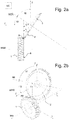
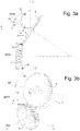
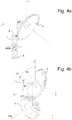
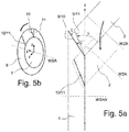
- This filing can be done, for example, in the in Figures 2a / 2b , Fig. 3a / 3b , Fig. 4a / 4b or Fig. 5a / 5b presented variants take place, which will be presented below. What all these variants have in common is that they are carried out with the same tool 2 as for skiving chamfering on the workpiece 1 in the same clamping of the workpiece 1, but using the second machining section 9.
- the azimuth angle ⁇ 2 is now set to 0 ° ("rotated back") for step 2).
- the tool 2 can be assigned a filing angle ⁇ .
- the filing angle ⁇ lies between the direction (envelope) of the first machining section 6 (here perpendicular to the tool axis WZA) and the direction (envelope) of the second machining section 9.
- the first and second machining sections 6, 9 are designed to be circumferential are.
- the file contact zone FZ in which the tool 2 touches the workpiece 1 in the context of step 2), is essentially at the same location as the contact zone in step 1) before; In this case, however, it is possible to move the contact between tool 2 and workpiece 1 on the end face in y and z on a circular path, if desired.
- Figures 3a and 3b show a variant in which the end face 8 is to be manufactured with a conical shape on the workpiece 1, corresponding to a cone angle ⁇ , which is approx. 10 ° here.
- the cone angle ⁇ is between the end face 8 the toothing of the workpiece 1 (cf. the auxiliary line of the end face extension 8a) and a radius vector 12 measured from the workpiece axis WSA, here in the xz plane.
- the azimuth angle ⁇ 2 is also set to 0 ° ("turned back") for step 2).
- the file contact zone FZ in which the tool 2 touches the workpiece 1 in the context of step 2), remains essentially at the same location as the contact zone in step 1) before.
- the azimuth angle ⁇ 2 was set to 0 ° for step 2). If, however, an azimuth angle ⁇ 2 greater than 0 ° is selected in step 2), the result is that the second machining section 9 effectively swivels away from the workpiece 1, and the second machining section 9 rests more steeply on the workpiece 1.
- 4b is always positive.
- an azimuth angle ⁇ 2 0 ° is set ("rotated back") in step 2).
- the polar angle ⁇ 2 remains unchanged compared to the polar angle ⁇ 1 from step 1).
- the filing edge angle ⁇ of the tool 2 is too small here to come to a linear contact with the conical end face 8 of the workpiece 1 to be manufactured (shown in bold) in the position shown above (shown with thin lines).
- This upper position corresponds to a location of the file contact zone, which is identical to the location of the contact zone from the previous step 1).
- There remains an opening angle which corresponds to a necessary offset angle ⁇ in order to achieve linear mutual contact.
- This opening angle is also in Figure 5b to see for the upper position, in which a local contour line 10 of the workpiece 1 (shown in bold) and a local contour line 11 of the tool (shown with thin lines) are indicated.
- step 2) it is also possible in step 2) to use an azimuth angle ⁇ 2 ⁇ 0 and an offset in the y and / or z direction of the file contact zone compared to the contact zone from step 1) in order to make the tool flat (linear) to be able to apply to the workpiece (not shown in detail). This enables a particularly high degree of flexibility in filing to be achieved.
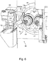
- Fig. 6 shows a device 40 for the combined skiving chamfering and filing of workpieces according to the invention.
- the device 40 has a station 41 for hobbing workpieces 1 with a hob 42 which is equipped with conventional axes of rotation and movement.
- the device 40 also has a station 43 for chamfering and filing workpieces 1, which is explained in more detail below;
- the station 43 is mostly also used for workpiece changes, since the chamfering and filing of a workpiece 1 usually takes less time than the hob milling of a workpiece 1.
- a rotary holder 44 which can be rotated in the direction of arrow 45 and thereby two workpiece spindles 46, 47 on the Can position stations 41, 43 and, in particular, interchange them.
- the rotary holder 44 is here rotatable about a horizontal axis, and the workpiece spindle axes, about which the workpieces 1 are rotatable, are also arranged horizontally here.
- workpieces 1 are clamped on a workpiece spindle 46, 47 at station 43, brought to station 41 for hob milling by turning rotary holder 44, brought back to station 41 for chamfering and filing by turning rotary holder 44, and unclamped again; this sequence takes place on both workpiece spindles 46, 47 in parallel and offset by half a phase.
- the station 43 for chamfering and filing workpieces 1 is explained in more detail below.
- a tool spindle 49 with a toothed tool 2 and also a further tool spindle 50 with a further toothed tool 51 are arranged here on a tool spindle holder 48.
- the tool 2 and here also the further tool 51 are each designed as a combination tool for skiving chamfering and filing with two machining sections (see e.g. Fig. 1 For this).
- the workpiece spindle holder 48 can be moved linearly along the mutually orthogonal directions x, y, z by means of a motorized moving device (cross slide system) 52, and can also be rotated with a motorized rotating device 53 about an axis of rotation DA, which runs parallel to the z direction .
- the x-direction is aligned horizontally and parallel to the workpiece spindle axis of the workpiece spindle 46, the y-direction runs vertically, and the z-direction again horizontally.
- a first bevel is being produced with the tool 2 on the tool spindle 49 on the workpiece 1 on the workpiece spindle 46 on its rear side; To this end, the tool 2 contacts the workpiece 1 with a first machining section from the left, that is, coming from the z-direction.
- the tool spindle holder 48 is repositioned with the motorized traversing device (compound slide system) 52 such that the further tool 51 on the further tool spindle 50 contacts the workpiece 1 from the left.
- tool axis WZA of the tool spindle 49 is pivoted downwards by an azimuth angle ⁇ 1 against the x-direction (cf. Workpiece spindle 50 is pivoted upwards by an opposite azimuth angle - ⁇ 1 against the x-direction (cf. the associated parallel-displaced x'-axis and the projection 13a of the further tool axis WWZA).
- tool axis WZA of the tool spindle 49 is pivoted by a polar angle ⁇ 1 against the z-direction (cf. -Direction is pivoted (see. Again, the associated parallel shifted axis z ').
- the workpiece 1 When filing, the workpiece 1 is machined with a second machining section of the tool 2.
- both chamfers of the workpiece 1 (left-hand and right-hand chamfers) of the here rear face of the workpiece 1 can be deburred in a single filing step with only one of the tools 2, 51 by filing; for this it is sufficient to design only one of the two tools 2, 51 as a combination tool with two machining sections.
- both tools 2, 51 are designed as combination tools, so that, as desired, only one of the tools 2, 51 or, alternatively, both tools 2, 51 can be used for filing.
- that tool 2, 51 is preferably used for filing on one face of a workpiece 1 with which the last of the two bevels was produced on this face of the workpiece 1, typically directly after the production of this last bevel.
- the workpiece 1 and the tool 2 respectively rotate.
- the rotation of the tool 2 takes place practically independently of the rotation of the workpiece 1.
- a differential speed between tool 2 and workpiece 1 is set; the workpiece 1 and the tool 2 rotate asynchronously to one another. Note that filing can be done both in the opposite direction and in the same direction.
- the tool spindle holder 48 is pivoted with the motorized rotating device 53 by 180 ° about the axis of rotation DA.
- the first bevel can then be made with the tool 2 and the second bevel can be made with the further tool 51 on the front side 54 of the workpiece 1, analogously to the above explanation (not shown in more detail). This can then be followed by filing, analogous to the explanation above (not shown in more detail).
Landscapes
- Engineering & Computer Science (AREA)
- Mechanical Engineering (AREA)
- Turning (AREA)
- Machine Tool Units (AREA)
Claims (15)
- Procédé d'usinage d'une pièce dentée (1), le procédé comprenant une
étape 1) de réalisation d'un chanfrein sur la pièce dentée (1) par décolletage en développante,
un outil (2) en rotation autour d'un axe d'outil (WZA) pourvu d'une première section d'usinage dentée (6) dans une zone de contact (KZ) glissant sur la pièce (1) en rotation autour d'un axe de pièce (WSA),
l'axe de pièce (WSA) définissant une direction x et la perpendiculaire de la zone de contact (KZ) à l'axe de pièce (WSA) définissant une direction z, et la direction x, une direction y et la direction z formant un système de coordonnées rectangulaire,
et l'axe d'outil (WZA) étant amené à pivoter par rapport à la direction x d'un angle d'azimut ϕ1 ≠ 0°, et l'axe d'outil (WZA) étant en outre amené à pivoter d'un angle polaire Θ1 < 90° par rapport à la direction z,
caractérisé en ce que
l'outil (2) est sélectionné comme un outil combiné qui, en plus de la première section d'usinage dentée (6), comporte en outre une deuxième section d'usinage (9), la deuxième section d'usinage (9) s'étendant, par rapport à un plan de coupe (SE) contenant l'axe d'outil (WZA), à un angle de coupe par limage α > 0° par rapport à la première section d'usinage (6),
en ce que le procédé comprend en outre une étape 2) de limage d'un côté frontal (8) de la pièce dentée (1) qui est adjacent au chanfrein réalisé à l'étape 1), l'outil rotatif (2) pourvu de la deuxième section d'usinage (9) dans une zone de contact de limage (FZ) glissant sur la pièce (1) en rotation autour de l'axe de pièce (WSA),
et en ce que les étapes 1) et 2) ont lieu dans le même serrage de la pièce (1). - Procédé selon la revendication 1, caractérisé en ce que le limage à l'étape 2) a lieu avec un angle polaire Θ2 de l'outil (2), qui est identique à l'angle polaire Θ1 lors de la réalisation du chanfrein par décolletage en développante à l'étape 1).
- Procédé selon la revendication 1 ou 2, caractérisé en ce que l'angle de coupe par limage α de l'outil (2) est sélectionné de telle sorte que : α = 90° - Θ2 + κ, avec κ : angle de conicité du côté frontal (8) de la pièce (1) par rapport à un vecteur de rayon (12) de la pièce (1).
- Procédé selon la revendication 3, caractérisé en ce que, dans l'étape 2), l'angle d'azimut est sélectionné pour ϕ2 = 0.
- Procédé selon la revendication 3, caractérisé en ce que, dans l'étape 2), l'angle d'azimut est sélectionné pour ϕ2 ≠ 0, et en outre la zone de contact de limage (FZ) est décalée par rapport à la zone de contact (KZ) de l'étape 1) dans la direction y et/ou dans la direction z.
- Procédé selon la revendication 1 ou 2, caractérisé en ce que l'angle de coupe par limage α de l'outil (2) est sélectionné de telle sorte que :

avec |ζ| > 0,
et en ce que, dans l'étape 2), l'angle d'azimut est sélectionné pour ϕ2 ≠ 0, et/ou la zone de contact de limage (FZ) est décalée par rapport à la zone de contact (KZ) de l'étape 1) dans la direction y et/ou dans la direction z. - Procédé selon l'une quelconque des revendications précédentes, caractérisé en ce que, dans le plan de coupe (SE) contenant l'axe d'outil (WZA), la première section d'usinage dentée (6) de l'outil (2) s'étend transversalement à l'axe d'outil (WZA).
- Procédé selon l'une quelconque des revendications précédentes, caractérisé en ce que, pour l'angle d'azimut ϕ1 dans l'étape 1) et un angle d'azimut ϕ2 dans l'étape 2 : |ϕ1| > |ϕ2|.
- Procédé selon l'une quelconque des revendications 1 à 8, caractérisé en ce que la deuxième section d'usinage (9) forme une coupe définie.
- Procédé selon l'une quelconque des revendications 1 à 8, caractérisé en ce que la deuxième section d'usinage (9) forme une coupe non définie.
- Dispositif (40) pour l'usinage d'une pièce dentée (1), le dispositif (40) étant configuré- avec une broche de pièce (46, 47) pour la rotation de la pièce dentée (1) autour d'un axe de pièce (WSA), qui s'étend le long d'une direction x,- avec une broche d'outil (49) pour la rotation d'un outil (2) autour d'un axe d'outil (WZA),- l'outil (2), qui est agencé sur la broche d'outil (49), étant pourvu d'une première section d'usinage dentée (6) pour la réalisation d'un chanfrein sur la pièce dentée (2) par décolletage en développante,- et avec un support de broche d'outil (48), sur lequel la broche d'outil (49) est supportée, le support de broche d'outil (48) étant déplaçable linéairement dans la direction x, une direction y et une direction z au moyen d'un appareil de déplacement motorisé (52), la direction x, la direction y et la direction z formant un système de coordonnées rectangulaire, le support de broche d'outil (48) pouvant être amené à pivoter au moyen d'un appareil de rotation motorisé (53) de telle sorte qu'au moins un angle d'azimut ϕ, avec lequel l'axe d'outil (WZA) est amené à pivoter par rapport à la direction x, puisse être réglé et qu'un angle d'azimut ϕ ≠ 0 puisse être ajusté, et en outre un angle polaire Θ < 90°, avec lequel l'axe d'outil (WZA) est amené à pivoter par rapport à la direction z, étant prédéterminé par le dispositif (40) ou pouvant être ajusté avec le dispositif (40),caractérisé en ce que
l'outil (2) est configuré comme outil combiné avec la première section d'usinage dentée (6) et en outre une deuxième section d'usinage (9) pour le limage d'un côté frontal (8) de la pièce (1), la deuxième section d'usinage (9) s'étendant, par rapport à un plan de coupe (SE) contenant l'axe d'outil (WZA), à un angle de coupe par limage α > 0° par rapport à la première section d'usinage (6),
et en ce que le dispositif (40) est configuré pour, successivement, avec la pièce dentée (1) agencée sur la broche de pièce (46, 47) dans le même serrage de la pièce (1), tout d'abord réaliser un chanfrein sur la pièce (1) par décolletage en développante avec la première section d'usinage dentée (6) et ensuite limer le côté frontal (8) de la pièce (1), qui est adjacent au chanfrein réalisé, avec la deuxième section d'usinage (9). - Dispositif (40) selon la revendication 11, caractérisé en ce que le support de broche d'outil (48) peut être mis en rotation au moyen de l'appareil de rotation motorisé (53) autour d'un axe de rotation (DA), qui s'étend le long de la direction z.
- Dispositif (40) selon la revendication 11 ou 12, caractérisé en ce que l'angle polaire Θ est prédéterminé par le dispositif (40).
- Dispositif (40) selon l'une quelconque des revendications 11 à 13, caractérisé en ce que la broche d'outil (49) et une broche d'outil supplémentaire (50) pour la mise en rotation d'un outil supplémentaire (51) autour d'un axe d'outil supplémentaire (WWZA) sont supportés sur le support de broche d'outil (48), l'outil supplémentaire (51) étant notamment également configuré comme outil combiné.
- Dispositif (40) selon l'une quelconque des revendications 11 à 14, caractérisé en ce que le dispositif (40) est configuré pour la réalisation d'un procédé selon l'une quelconque des revendications 1 à 10.
Applications Claiming Priority (2)
| Application Number | Priority Date | Filing Date | Title |
|---|---|---|---|
| DE102017204891.3A DE102017204891A1 (de) | 2017-03-23 | 2017-03-23 | Verfahren zum kombinierten Wälzschälanfasen und Feilen eines Werkstücks |
| PCT/EP2018/057426 WO2018172516A1 (fr) | 2017-03-23 | 2018-03-23 | Procédé combiné de chanfreinage par décolletage en développante et de limage d'une pièce |
Publications (2)
| Publication Number | Publication Date |
|---|---|
| EP3600743A1 EP3600743A1 (fr) | 2020-02-05 |
| EP3600743B1 true EP3600743B1 (fr) | 2021-08-04 |
Family
ID=61801932
Family Applications (1)
| Application Number | Title | Priority Date | Filing Date |
|---|---|---|---|
| EP18713867.2A Active EP3600743B1 (fr) | 2017-03-23 | 2018-03-23 | Procédé combiné de chanfreinage par décolletage en développante et de limage d'une pièce |
Country Status (3)
| Country | Link |
|---|---|
| EP (1) | EP3600743B1 (fr) |
| DE (1) | DE102017204891A1 (fr) |
| WO (1) | WO2018172516A1 (fr) |
Cited By (1)
| Publication number | Priority date | Publication date | Assignee | Title |
|---|---|---|---|---|
| WO2023105199A1 (fr) * | 2021-12-08 | 2023-06-15 | Lleu Limited | Chanfreinage de pièce à travailler |
Families Citing this family (4)
| Publication number | Priority date | Publication date | Assignee | Title |
|---|---|---|---|---|
| CN110465706A (zh) * | 2019-07-10 | 2019-11-19 | 西安理工大学 | 硬齿面齿轮精车工艺及其车齿刀具设计方法 |
| JP7451900B2 (ja) * | 2019-08-21 | 2024-03-19 | 株式会社ジェイテクト | 歯溝加工方法及び歯溝加工装置 |
| DE102019131266A1 (de) | 2019-11-20 | 2021-05-20 | Schaeffler Technologies AG & Co. KG | Verfahren und Vorrichtung zum Entgraten eines innenverzahnten Werkstücks |
| DE102022117192B4 (de) * | 2022-07-11 | 2025-08-21 | Präwema Antriebstechnik GmbH | Werkzeug und Verfahren zum spanenden Entgraten und/oder Anfasen einer eine Mehrzahl von Werkstückzähnen umfassenden Werkstückverzahnung |
Family Cites Families (5)
| Publication number | Priority date | Publication date | Assignee | Title |
|---|---|---|---|---|
| DE10309116A1 (de) * | 2003-02-28 | 2004-09-09 | Wera Werk Hermann Werner Gmbh & Co. Kg | Kombinationswerkzeug zur Bearbeitung von Zahnradzähnen |
| DE102014008475B4 (de) * | 2014-06-05 | 2023-02-23 | Gleason-Pfauter Maschinenfabrik Gmbh | Verfahren zum Bearbeiten eines Werkstücks, Werkzeuganordnung und Verzahnungsmaschine |
| DE102014013230A1 (de) * | 2014-09-05 | 2016-03-10 | Gleason-Pfauter Maschinenfabrik Gmbh | Verfahren zum Bearbeiten einer Verzahnung, Bearbeitungswerkzeug und Werkzeugmaschine |
| DE102014019740B4 (de) * | 2014-09-10 | 2016-11-10 | Felsomat Gmbh & Co. Kg | Vorrichtung zur Wälzschälbearbeitung eines Werkstücks zur Fertigung einer Fase mit rotierbarer Werkzeugspindel-Halterung und zugehöriges Betriebsverfahren |
| DE102014218082B4 (de) | 2014-09-10 | 2016-11-10 | Felsomat Gmbh & Co. Kg | Vorrichtung zur Wälzschälbearbeitung eines Werkstücks zur Fertigung einer Fase und zugehöriges Betriebsverfahren |
-
2017
- 2017-03-23 DE DE102017204891.3A patent/DE102017204891A1/de not_active Withdrawn
-
2018
- 2018-03-23 EP EP18713867.2A patent/EP3600743B1/fr active Active
- 2018-03-23 WO PCT/EP2018/057426 patent/WO2018172516A1/fr not_active Ceased
Cited By (1)
| Publication number | Priority date | Publication date | Assignee | Title |
|---|---|---|---|---|
| WO2023105199A1 (fr) * | 2021-12-08 | 2023-06-15 | Lleu Limited | Chanfreinage de pièce à travailler |
Also Published As
| Publication number | Publication date |
|---|---|
| EP3600743A1 (fr) | 2020-02-05 |
| WO2018172516A1 (fr) | 2018-09-27 |
| DE102017204891A1 (de) | 2018-09-27 |
Similar Documents
| Publication | Publication Date | Title |
|---|---|---|
| EP3191248B1 (fr) | Dispositif de taillage en développante d'une pièce pour la production d'un chanfrein et procédé de fonctionnement associé | |
| EP3600743B1 (fr) | Procédé combiné de chanfreinage par décolletage en développante et de limage d'une pièce | |
| EP2946865B1 (fr) | Procédé de détermination de position de développantes pour des engrenages | |
| EP3412395B1 (fr) | Dispositifs et procédé de chanfreinage d'une pièce à denture intérieure | |
| EP3552743A1 (fr) | Dispositif et procédé de traitement par chanfreinage d'une pièce à dents à usiner | |
| EP3546101B1 (fr) | Procédé et dispositif servant à tailler des roues d'usinage par décolletage en développante | |
| DE102018108632A1 (de) | Vorrichtung zur Anfasbearbeitung eines Werkstücks | |
| EP3388179A1 (fr) | Procédé d'usinage de denture d'une pièce à usiner | |
| EP3959028B1 (fr) | Procédé et dispositif pour la fabrication de pièces dentées, en particulier de manchons coulissants, ainsi qu'outil correspondant | |
| DE102014019740B4 (de) | Vorrichtung zur Wälzschälbearbeitung eines Werkstücks zur Fertigung einer Fase mit rotierbarer Werkzeugspindel-Halterung und zugehöriges Betriebsverfahren | |
| DE202017106229U1 (de) | Bearbeitungsvorrichtung | |
| DE102019005405A1 (de) | Verfahren zum Hartfeinbearbeiten zweier Verzahnungen an einem Werkstück | |
| DE202016103064U1 (de) | Vorrichtung zur spanenden Bearbeitung eines rotierenden Werkstücks | |
| DE2604281A1 (de) | Maschine zum schaben und/oder profilrollen der verzahnung von zahnraedern | |
| EP2961552A1 (fr) | Procédé de fabrication ou d'usinage par enlèvement de matière d'une denture, et machine de taillage d'engrenages | |
| EP3349934A1 (fr) | Procédé et dispositif de fabrication et d'ébavurage de dentures | |
| EP3013505B1 (fr) | Machine à tailler par fraise-mère pourvue d'un bras pivotant sur lequel sont disposés un dispositif de chanfreinage et deux outils de coupe | |
| DE102010051284B4 (de) | Verfahren und Werkzeugmaschine zum Herstellen von schrägstehenden Nuten in der Außen- oder Innenumfangsfläche eines rotationssymmetrischen Grundkörpers | |
| DE19544301C2 (de) | Verfahren und Vorrichtung zum Formstechen und Formdrehen | |
| DE102014019817B3 (de) | Vorrichtung zum Wälzfräsen sowie zur Wälzschälbearbeitung eines Werkstücks zur Fertigung einer Fase und zugehöriges Betriebsverfahren | |
| DE102013010246A1 (de) | Verfahren zur Verzahnbearbeitung von Werkstücken | |
| DE102024120994A1 (de) | Vorrichtung zur Anfasbearbeitung | |
| DE102023111950A1 (de) | Vorrichtung und Verfahren zum Anfasen von Zahnkanten | |
| EP3479936A1 (fr) | Tournage de pièces à usiner sur une machine-outil | |
| DE4312199A1 (de) | Verfahren zum Schleifen der Zahnschneiden eines Fräsers |
Legal Events
| Date | Code | Title | Description |
|---|---|---|---|
| STAA | Information on the status of an ep patent application or granted ep patent |
Free format text: STATUS: UNKNOWN |
|
| STAA | Information on the status of an ep patent application or granted ep patent |
Free format text: STATUS: THE INTERNATIONAL PUBLICATION HAS BEEN MADE |
|
| PUAI | Public reference made under article 153(3) epc to a published international application that has entered the european phase |
Free format text: ORIGINAL CODE: 0009012 |
|
| STAA | Information on the status of an ep patent application or granted ep patent |
Free format text: STATUS: REQUEST FOR EXAMINATION WAS MADE |
|
| 17P | Request for examination filed |
Effective date: 20191023 |
|
| AK | Designated contracting states |
Kind code of ref document: A1 Designated state(s): AL AT BE BG CH CY CZ DE DK EE ES FI FR GB GR HR HU IE IS IT LI LT LU LV MC MK MT NL NO PL PT RO RS SE SI SK SM TR |
|
| AX | Request for extension of the european patent |
Extension state: BA ME |
|
| DAV | Request for validation of the european patent (deleted) | ||
| DAX | Request for extension of the european patent (deleted) | ||
| GRAP | Despatch of communication of intention to grant a patent |
Free format text: ORIGINAL CODE: EPIDOSNIGR1 |
|
| STAA | Information on the status of an ep patent application or granted ep patent |
Free format text: STATUS: GRANT OF PATENT IS INTENDED |
|
| INTG | Intention to grant announced |
Effective date: 20210312 |
|
| GRAS | Grant fee paid |
Free format text: ORIGINAL CODE: EPIDOSNIGR3 |
|
| GRAA | (expected) grant |
Free format text: ORIGINAL CODE: 0009210 |
|
| STAA | Information on the status of an ep patent application or granted ep patent |
Free format text: STATUS: THE PATENT HAS BEEN GRANTED |
|
| AK | Designated contracting states |
Kind code of ref document: B1 Designated state(s): AL AT BE BG CH CY CZ DE DK EE ES FI FR GB GR HR HU IE IS IT LI LT LU LV MC MK MT NL NO PL PT RO RS SE SI SK SM TR |
|
| REG | Reference to a national code |
Ref country code: GB Ref legal event code: FG4D Free format text: NOT ENGLISH |
|
| REG | Reference to a national code |
Ref country code: AT Ref legal event code: REF Ref document number: 1416470 Country of ref document: AT Kind code of ref document: T Effective date: 20210815 |
|
| REG | Reference to a national code |
Ref country code: CH Ref legal event code: EP |
|
| REG | Reference to a national code |
Ref country code: DE Ref legal event code: R096 Ref document number: 502018006421 Country of ref document: DE |
|
| REG | Reference to a national code |
Ref country code: IE Ref legal event code: FG4D Free format text: LANGUAGE OF EP DOCUMENT: GERMAN |
|
| REG | Reference to a national code |
Ref country code: LT Ref legal event code: MG9D |
|
| REG | Reference to a national code |
Ref country code: NL Ref legal event code: MP Effective date: 20210804 |
|
| PG25 | Lapsed in a contracting state [announced via postgrant information from national office to epo] |
Ref country code: RS Free format text: LAPSE BECAUSE OF FAILURE TO SUBMIT A TRANSLATION OF THE DESCRIPTION OR TO PAY THE FEE WITHIN THE PRESCRIBED TIME-LIMIT Effective date: 20210804 Ref country code: SE Free format text: LAPSE BECAUSE OF FAILURE TO SUBMIT A TRANSLATION OF THE DESCRIPTION OR TO PAY THE FEE WITHIN THE PRESCRIBED TIME-LIMIT Effective date: 20210804 Ref country code: ES Free format text: LAPSE BECAUSE OF FAILURE TO SUBMIT A TRANSLATION OF THE DESCRIPTION OR TO PAY THE FEE WITHIN THE PRESCRIBED TIME-LIMIT Effective date: 20210804 Ref country code: FI Free format text: LAPSE BECAUSE OF FAILURE TO SUBMIT A TRANSLATION OF THE DESCRIPTION OR TO PAY THE FEE WITHIN THE PRESCRIBED TIME-LIMIT Effective date: 20210804 Ref country code: HR Free format text: LAPSE BECAUSE OF FAILURE TO SUBMIT A TRANSLATION OF THE DESCRIPTION OR TO PAY THE FEE WITHIN THE PRESCRIBED TIME-LIMIT Effective date: 20210804 Ref country code: NO Free format text: LAPSE BECAUSE OF FAILURE TO SUBMIT A TRANSLATION OF THE DESCRIPTION OR TO PAY THE FEE WITHIN THE PRESCRIBED TIME-LIMIT Effective date: 20211104 Ref country code: PT Free format text: LAPSE BECAUSE OF FAILURE TO SUBMIT A TRANSLATION OF THE DESCRIPTION OR TO PAY THE FEE WITHIN THE PRESCRIBED TIME-LIMIT Effective date: 20211206 Ref country code: BG Free format text: LAPSE BECAUSE OF FAILURE TO SUBMIT A TRANSLATION OF THE DESCRIPTION OR TO PAY THE FEE WITHIN THE PRESCRIBED TIME-LIMIT Effective date: 20211104 Ref country code: LT Free format text: LAPSE BECAUSE OF FAILURE TO SUBMIT A TRANSLATION OF THE DESCRIPTION OR TO PAY THE FEE WITHIN THE PRESCRIBED TIME-LIMIT Effective date: 20210804 |
|
| PG25 | Lapsed in a contracting state [announced via postgrant information from national office to epo] |
Ref country code: PL Free format text: LAPSE BECAUSE OF FAILURE TO SUBMIT A TRANSLATION OF THE DESCRIPTION OR TO PAY THE FEE WITHIN THE PRESCRIBED TIME-LIMIT Effective date: 20210804 Ref country code: LV Free format text: LAPSE BECAUSE OF FAILURE TO SUBMIT A TRANSLATION OF THE DESCRIPTION OR TO PAY THE FEE WITHIN THE PRESCRIBED TIME-LIMIT Effective date: 20210804 Ref country code: GR Free format text: LAPSE BECAUSE OF FAILURE TO SUBMIT A TRANSLATION OF THE DESCRIPTION OR TO PAY THE FEE WITHIN THE PRESCRIBED TIME-LIMIT Effective date: 20211105 |
|
| PG25 | Lapsed in a contracting state [announced via postgrant information from national office to epo] |
Ref country code: NL Free format text: LAPSE BECAUSE OF FAILURE TO SUBMIT A TRANSLATION OF THE DESCRIPTION OR TO PAY THE FEE WITHIN THE PRESCRIBED TIME-LIMIT Effective date: 20210804 |
|
| PG25 | Lapsed in a contracting state [announced via postgrant information from national office to epo] |
Ref country code: DK Free format text: LAPSE BECAUSE OF FAILURE TO SUBMIT A TRANSLATION OF THE DESCRIPTION OR TO PAY THE FEE WITHIN THE PRESCRIBED TIME-LIMIT Effective date: 20210804 |
|
| REG | Reference to a national code |
Ref country code: DE Ref legal event code: R097 Ref document number: 502018006421 Country of ref document: DE |
|
| PG25 | Lapsed in a contracting state [announced via postgrant information from national office to epo] |
Ref country code: SM Free format text: LAPSE BECAUSE OF FAILURE TO SUBMIT A TRANSLATION OF THE DESCRIPTION OR TO PAY THE FEE WITHIN THE PRESCRIBED TIME-LIMIT Effective date: 20210804 Ref country code: SK Free format text: LAPSE BECAUSE OF FAILURE TO SUBMIT A TRANSLATION OF THE DESCRIPTION OR TO PAY THE FEE WITHIN THE PRESCRIBED TIME-LIMIT Effective date: 20210804 Ref country code: RO Free format text: LAPSE BECAUSE OF FAILURE TO SUBMIT A TRANSLATION OF THE DESCRIPTION OR TO PAY THE FEE WITHIN THE PRESCRIBED TIME-LIMIT Effective date: 20210804 Ref country code: EE Free format text: LAPSE BECAUSE OF FAILURE TO SUBMIT A TRANSLATION OF THE DESCRIPTION OR TO PAY THE FEE WITHIN THE PRESCRIBED TIME-LIMIT Effective date: 20210804 Ref country code: CZ Free format text: LAPSE BECAUSE OF FAILURE TO SUBMIT A TRANSLATION OF THE DESCRIPTION OR TO PAY THE FEE WITHIN THE PRESCRIBED TIME-LIMIT Effective date: 20210804 Ref country code: AL Free format text: LAPSE BECAUSE OF FAILURE TO SUBMIT A TRANSLATION OF THE DESCRIPTION OR TO PAY THE FEE WITHIN THE PRESCRIBED TIME-LIMIT Effective date: 20210804 |
|
| PLBE | No opposition filed within time limit |
Free format text: ORIGINAL CODE: 0009261 |
|
| STAA | Information on the status of an ep patent application or granted ep patent |
Free format text: STATUS: NO OPPOSITION FILED WITHIN TIME LIMIT |
|
| 26N | No opposition filed |
Effective date: 20220506 |
|
| PG25 | Lapsed in a contracting state [announced via postgrant information from national office to epo] |
Ref country code: SI Free format text: LAPSE BECAUSE OF FAILURE TO SUBMIT A TRANSLATION OF THE DESCRIPTION OR TO PAY THE FEE WITHIN THE PRESCRIBED TIME-LIMIT Effective date: 20210804 |
|
| PG25 | Lapsed in a contracting state [announced via postgrant information from national office to epo] |
Ref country code: MC Free format text: LAPSE BECAUSE OF FAILURE TO SUBMIT A TRANSLATION OF THE DESCRIPTION OR TO PAY THE FEE WITHIN THE PRESCRIBED TIME-LIMIT Effective date: 20210804 |
|
| REG | Reference to a national code |
Ref country code: CH Ref legal event code: PL |
|
| GBPC | Gb: european patent ceased through non-payment of renewal fee |
Effective date: 20220323 |
|
| REG | Reference to a national code |
Ref country code: BE Ref legal event code: MM Effective date: 20220331 |
|
| PG25 | Lapsed in a contracting state [announced via postgrant information from national office to epo] |
Ref country code: LU Free format text: LAPSE BECAUSE OF NON-PAYMENT OF DUE FEES Effective date: 20220323 Ref country code: LI Free format text: LAPSE BECAUSE OF NON-PAYMENT OF DUE FEES Effective date: 20220331 Ref country code: IE Free format text: LAPSE BECAUSE OF NON-PAYMENT OF DUE FEES Effective date: 20220323 Ref country code: GB Free format text: LAPSE BECAUSE OF NON-PAYMENT OF DUE FEES Effective date: 20220323 Ref country code: CH Free format text: LAPSE BECAUSE OF NON-PAYMENT OF DUE FEES Effective date: 20220331 |
|
| PG25 | Lapsed in a contracting state [announced via postgrant information from national office to epo] |
Ref country code: BE Free format text: LAPSE BECAUSE OF NON-PAYMENT OF DUE FEES Effective date: 20220331 |
|
| PGFP | Annual fee paid to national office [announced via postgrant information from national office to epo] |
Ref country code: AT Payment date: 20240318 Year of fee payment: 7 |
|
| PG25 | Lapsed in a contracting state [announced via postgrant information from national office to epo] |
Ref country code: MK Free format text: LAPSE BECAUSE OF FAILURE TO SUBMIT A TRANSLATION OF THE DESCRIPTION OR TO PAY THE FEE WITHIN THE PRESCRIBED TIME-LIMIT Effective date: 20210804 Ref country code: CY Free format text: LAPSE BECAUSE OF FAILURE TO SUBMIT A TRANSLATION OF THE DESCRIPTION OR TO PAY THE FEE WITHIN THE PRESCRIBED TIME-LIMIT Effective date: 20210804 |
|
| PGFP | Annual fee paid to national office [announced via postgrant information from national office to epo] |
Ref country code: DE Payment date: 20240325 Year of fee payment: 7 |
|
| PG25 | Lapsed in a contracting state [announced via postgrant information from national office to epo] |
Ref country code: HU Free format text: LAPSE BECAUSE OF FAILURE TO SUBMIT A TRANSLATION OF THE DESCRIPTION OR TO PAY THE FEE WITHIN THE PRESCRIBED TIME-LIMIT; INVALID AB INITIO Effective date: 20180323 |
|
| PGFP | Annual fee paid to national office [announced via postgrant information from national office to epo] |
Ref country code: IT Payment date: 20240329 Year of fee payment: 7 Ref country code: FR Payment date: 20240320 Year of fee payment: 7 |
|
| PG25 | Lapsed in a contracting state [announced via postgrant information from national office to epo] |
Ref country code: TR Free format text: LAPSE BECAUSE OF FAILURE TO SUBMIT A TRANSLATION OF THE DESCRIPTION OR TO PAY THE FEE WITHIN THE PRESCRIBED TIME-LIMIT Effective date: 20210804 |
|
| PG25 | Lapsed in a contracting state [announced via postgrant information from national office to epo] |
Ref country code: MT Free format text: LAPSE BECAUSE OF FAILURE TO SUBMIT A TRANSLATION OF THE DESCRIPTION OR TO PAY THE FEE WITHIN THE PRESCRIBED TIME-LIMIT Effective date: 20210804 |
|
| REG | Reference to a national code |
Ref country code: DE Ref legal event code: R119 Ref document number: 502018006421 Country of ref document: DE |
|
| REG | Reference to a national code |
Ref country code: AT Ref legal event code: MM01 Ref document number: 1416470 Country of ref document: AT Kind code of ref document: T Effective date: 20250323 |
|
| PG25 | Lapsed in a contracting state [announced via postgrant information from national office to epo] |
Ref country code: DE Free format text: LAPSE BECAUSE OF NON-PAYMENT OF DUE FEES Effective date: 20251001 |
|
| PG25 | Lapsed in a contracting state [announced via postgrant information from national office to epo] |
Ref country code: AT Free format text: LAPSE BECAUSE OF NON-PAYMENT OF DUE FEES Effective date: 20250323 |
|
| PG25 | Lapsed in a contracting state [announced via postgrant information from national office to epo] |
Ref country code: FR Free format text: LAPSE BECAUSE OF NON-PAYMENT OF DUE FEES Effective date: 20250331 Ref country code: IT Free format text: LAPSE BECAUSE OF NON-PAYMENT OF DUE FEES Effective date: 20250323 |