EP3600754B1 - Düse für eine laserbeschichtungsanornung - Google Patents
Düse für eine laserbeschichtungsanornung Download PDFInfo
- Publication number
- EP3600754B1 EP3600754B1 EP18777171.2A EP18777171A EP3600754B1 EP 3600754 B1 EP3600754 B1 EP 3600754B1 EP 18777171 A EP18777171 A EP 18777171A EP 3600754 B1 EP3600754 B1 EP 3600754B1
- Authority
- EP
- European Patent Office
- Prior art keywords
- tube
- injection nozzle
- powder injection
- inlet
- nozzle
- Prior art date
- Legal status (The legal status is an assumption and is not a legal conclusion. Google has not performed a legal analysis and makes no representation as to the accuracy of the status listed.)
- Active
Links
Images


Classifications
-
- B—PERFORMING OPERATIONS; TRANSPORTING
- B23—MACHINE TOOLS; METAL-WORKING NOT OTHERWISE PROVIDED FOR
- B23K—SOLDERING OR UNSOLDERING; WELDING; CLADDING OR PLATING BY SOLDERING OR WELDING; CUTTING BY APPLYING HEAT LOCALLY, e.g. FLAME CUTTING; WORKING BY LASER BEAM
- B23K26/00—Working by laser beam, e.g. welding, cutting or boring
- B23K26/14—Working by laser beam, e.g. welding, cutting or boring using a fluid stream, e.g. a jet of gas, in conjunction with the laser beam; Nozzles therefor
- B23K26/144—Working by laser beam, e.g. welding, cutting or boring using a fluid stream, e.g. a jet of gas, in conjunction with the laser beam; Nozzles therefor the fluid stream containing particles, e.g. powder
-
- B—PERFORMING OPERATIONS; TRANSPORTING
- B05—SPRAYING OR ATOMISING IN GENERAL; APPLYING FLUENT MATERIALS TO SURFACES, IN GENERAL
- B05B—SPRAYING APPARATUS; ATOMISING APPARATUS; NOZZLES
- B05B7/00—Spraying apparatus for discharge of liquids or other fluent materials from two or more sources, e.g. of liquid and air, of powder and gas
- B05B7/14—Spraying apparatus for discharge of liquids or other fluent materials from two or more sources, e.g. of liquid and air, of powder and gas designed for spraying particulate materials
- B05B7/1481—Spray pistols or apparatus for discharging particulate material
- B05B7/1486—Spray pistols or apparatus for discharging particulate material for spraying particulate material in dry state
-
- B—PERFORMING OPERATIONS; TRANSPORTING
- B23—MACHINE TOOLS; METAL-WORKING NOT OTHERWISE PROVIDED FOR
- B23K—SOLDERING OR UNSOLDERING; WELDING; CLADDING OR PLATING BY SOLDERING OR WELDING; CUTTING BY APPLYING HEAT LOCALLY, e.g. FLAME CUTTING; WORKING BY LASER BEAM
- B23K26/00—Working by laser beam, e.g. welding, cutting or boring
- B23K26/12—Working by laser beam, e.g. welding, cutting or boring in a special environment or atmosphere, e.g. in an enclosure
- B23K26/123—Working by laser beam, e.g. welding, cutting or boring in a special environment or atmosphere, e.g. in an enclosure in an atmosphere of particular gases
-
- B—PERFORMING OPERATIONS; TRANSPORTING
- B23—MACHINE TOOLS; METAL-WORKING NOT OTHERWISE PROVIDED FOR
- B23K—SOLDERING OR UNSOLDERING; WELDING; CLADDING OR PLATING BY SOLDERING OR WELDING; CUTTING BY APPLYING HEAT LOCALLY, e.g. FLAME CUTTING; WORKING BY LASER BEAM
- B23K26/00—Working by laser beam, e.g. welding, cutting or boring
- B23K26/14—Working by laser beam, e.g. welding, cutting or boring using a fluid stream, e.g. a jet of gas, in conjunction with the laser beam; Nozzles therefor
- B23K26/146—Working by laser beam, e.g. welding, cutting or boring using a fluid stream, e.g. a jet of gas, in conjunction with the laser beam; Nozzles therefor the fluid stream containing a liquid
-
- B—PERFORMING OPERATIONS; TRANSPORTING
- B23—MACHINE TOOLS; METAL-WORKING NOT OTHERWISE PROVIDED FOR
- B23K—SOLDERING OR UNSOLDERING; WELDING; CLADDING OR PLATING BY SOLDERING OR WELDING; CUTTING BY APPLYING HEAT LOCALLY, e.g. FLAME CUTTING; WORKING BY LASER BEAM
- B23K26/00—Working by laser beam, e.g. welding, cutting or boring
- B23K26/14—Working by laser beam, e.g. welding, cutting or boring using a fluid stream, e.g. a jet of gas, in conjunction with the laser beam; Nozzles therefor
- B23K26/1462—Nozzles; Features related to nozzles
- B23K26/1464—Supply to, or discharge from, nozzles of media, e.g. gas, powder, wire
- B23K26/147—Features outside the nozzle for feeding the fluid stream towards the workpiece
-
- B—PERFORMING OPERATIONS; TRANSPORTING
- B23—MACHINE TOOLS; METAL-WORKING NOT OTHERWISE PROVIDED FOR
- B23K—SOLDERING OR UNSOLDERING; WELDING; CLADDING OR PLATING BY SOLDERING OR WELDING; CUTTING BY APPLYING HEAT LOCALLY, e.g. FLAME CUTTING; WORKING BY LASER BEAM
- B23K26/00—Working by laser beam, e.g. welding, cutting or boring
- B23K26/14—Working by laser beam, e.g. welding, cutting or boring using a fluid stream, e.g. a jet of gas, in conjunction with the laser beam; Nozzles therefor
- B23K26/1462—Nozzles; Features related to nozzles
- B23K26/1494—Maintenance of nozzles
-
- B—PERFORMING OPERATIONS; TRANSPORTING
- B23—MACHINE TOOLS; METAL-WORKING NOT OTHERWISE PROVIDED FOR
- B23K—SOLDERING OR UNSOLDERING; WELDING; CLADDING OR PLATING BY SOLDERING OR WELDING; CUTTING BY APPLYING HEAT LOCALLY, e.g. FLAME CUTTING; WORKING BY LASER BEAM
- B23K26/00—Working by laser beam, e.g. welding, cutting or boring
- B23K26/34—Laser welding for purposes other than joining
Definitions
- the present invention relates generally to methods, systems and assemblies for deposition of metallurgically bonded layers onto surfaces of metallic substrates, by laser deposition.
- a common purpose for surface coatings is to tailor or improve wear resistance characteristics and the present invention will be described primarily with reference to such applications. It should be appreciated, however, that the invention may be utilised for application of surface layers and coatings for a broad range of functional, structural and aesthetic applications including but not limited to wear or abrasion resistance, thermal insulation, corrosion and chemical resistance, electrical conductivity or resistivity, medical or bio-medical compatibility, RFI/EMI shielding, surface colour, pattern or texture, dimensional restoration and cosmetic repair.
- Laser cladding utilises controlled energy from a laser source to bond a surfacing material to a metallic component.
- Laser cladding techniques utilise the energy of a laser beam to form a metallurgically bonded layer on the metal base.
- Lasers that may be used for this purpose include CO 2 , Nd:YAG, Nd:YVO 4 , Diode, Disc and Fibre lasers.
- Laser based systems provide a number of advantages over other techniques including highly variable energy adjustment, strong metallurgical bonds, lower dilution with the base metal, smaller heat affected zones, lower deleterious heat affects to the base material and deposited layer, minimal distortion, and high heating and cooling rates resulting in relatively fine microstructures and metastable phases.
- known laser cladding system are typically difficult to set up, with only limited adjustability available to accommodate complex and irregular shaped components.
- such systems are typically adapted for use with relatively small and lightweight components with little or no capacity for larger workpieces.
- Coaxial laser cladding heads typically include a laser beam projecting from the centre of the cladding head.
- the laser beam is positioned to project as a spot on the surface of a component.
- Powder is directed under pressure toward a component to which a cladding is to be applied from points located around the laser beam.
- the streams of powder are directed to focus on a single region within or adjacent the laser spot.
- Such a co-axial system is relatively insensitive to the direction that the cladding head is travelling.
- the pressurised powder often bounces off the component to be clad and adjustability of the powder supply is low.
- the laser beam and stream of powder are not co-axial but rather are directed toward the component from adjacent sources.
- the rate of material applied to the laser spot can be more easily and accurately controlled, however, it remains difficult to accurately position and adjust the nozzle relative to the laser beam.
- the tip of the powder injection tube must be located in very close proximity to a high energy, focussed laser beam. This close proximity necessarily ensures that the nozzle tip is prone to excessive heat which can melt the tip by way of direct or reflected laser energy, leading to generally inefficient systems and relatively long downtimes for maintenance and repair with associated losses in production time and related labour costs.
- US 5486676 discloses a laser welding apparatus with a powder feed nozzle for ejecting welding powder metal. Powdered metal travels through an inner tube, disposed coaxially within an outer tube, and is ejected out of a powder outlet. A shaping gas travels through the annulus defined between the inner and outer tubes and defines a shaping annulus around the powdered metal when it exits an outlet of the outer tube. The flowrate of the shaping gas can be altered to change the shape of the powdered metal when it is ejected from the nozzle.
- WO 2016/132502 also provides a cylindrical powder nozzle for a laser welding apparatus with a powder nozzle, which delivers powdered welding material, coaxially disposed within a shield nozzle, which provides a shield gas to isolate the weld point from the atmosphere.
- GB 2228224 presents an apparatus for laser welding of so-called 'blisks' for compressors in aircraft engines.
- the apparatus has a water-cooled nozzle with a tip portion made of aluminium or copper that reflects the wavelength of the laser used in the welding process: both the water-cooling and the choice of material for the nozzle tip help to prevent the clogging of powder passing through the nozzle.
- a powder injection nozzle for a laser cladding system including:
- the gas inlet includes a gas inlet tube having a first free open for connection to a gas supply line and second fixed end fixed in or about a hole formed in a wall of the body, thereby to provide a passageway for the gas from the first free end to the interior of the body.
- the gas inlet tube includes a first portion defining the first free end and extending parallel to the longitudinal axis of the body and a second portion extending at an angle to the first portion.
- the second portion extends at an angle in the range of 15-50 degrees relative to the first portion, preferably 20-45 degrees and more preferably 25-35 degrees. In one particularly preferred embodiment, the second portion extends at an angle of 30 degrees relative to the first portion.
- the body has an inner diameter in the range of 8-25mm, preferably 9-15mm and more preferably 10-12mm. In certain embodiments, the length of the body is in the range of 90-150mm, preferably 100-140mm and more preferably 110-130mm.
- the insert may include two or more openings arranged to form a polar array of openings about the tube.
- each opening may have a diameter equal to or less than 1mm, preferably about 0.7mm.
- the insert includes a polar array with eight holes arranged about the tube. It will be appreciated that the number, size and arrangement of the holes may vary to suit a particular application and is not limited to those described herein.
- the tube has a constant cross-sectional diameter along its length.
- the tube has an outer diameter in the range of 2-7mm, preferably 3-6mm and more preferably 3.5-5mm.
- the tube has an outer diameter of 4mm and a wall thickness of 0.45mm.
- the body and tube are coaxially aligned.
- the length of the tube is in the range of 100-220mm, preferably 140-180mm and more preferably 150-170mm. In one preferred embodiment, the tube has a length of 160mm.
- the nozzle tip projects approximately 5mm forward of the distal end of the body. In certain embodiments, the inlet of the tube projects approximately 30-45mm rearwardly of the distal end of the body.
- the cladding material is preferably a powdered material or other particulate matter.
- the powder injection nozzle includes a fluid delivery unit for delivering a cooling fluid to the distal end region of the powder injection nozzle.
- the fluid delivery unit includes a water cooling mechanism adapted to control and cool the temperature of the distal end of the tube (nozzle tip) and/or body, in use.
- the water cooling mechanism is particularly advantageous in laser cladding applications in which the nozzle tip is required to be located in very close proximity to a laser beam and thus subject to extreme temperatures which can result in premature failure or reduced working life of the powder injection nozzle, particularly the nozzle tip of the tube.
- the water cooling mechanism includes a sleeve fixed to and bounding at least a portion of the body, thereby to form an enclosed area between an inner surface of the sleeve and an outer surface or wall of the body.
- sleeve is coaxially aligned with the body, whereby a cross-sectional profile of the enclosed area is in the form of an annulus or ring.
- the sleeve is arranged to bound a portion of the body at or adjacent to the distal end of the body.
- the length of the sleeve is less than the length of the body.
- the sleeve is adapted to extend for approximately half the length of the body. It will be appreciated that, in other forms, the extent to which the sleeve extends along the body may be greater than or less than half the length of the body.
- the ratio of the length of the body to the length of the sleeve is approximately 2:1. In other embodiments, the ratio of the length of the body to the length of the sleeve is approximately 1.7:1. It will be appreciated that, in other forms, the extent to which the sleeve extends along the body is not limited to the above exemplary figures and, in particular, the length of the sleeve may be greater than or less than half of the length of the body.
- the sleeve of the water cooling mechanism includes at least a first inlet hole formed in the wall of the sleeve and through which water can be charged into the enclosed area between the sleeve and the body and circulated about the enclosed area, and a second outlet hole formed in the wall of the sleeve through which water can be discharged from the sleeve, thereby to cool the associated regions of the body, tube and nozzle tip in use.
- the water cooling mechanism includes a water inlet pipe having a first free open end for connection (via a hose or other suitable duct) to a water supply line and second fixed end fixed in or about the first inlet hole formed in the wall of the sleeve, thereby to provide a passageway for water to be charged to the enclosed area.
- the water inlet pipe includes a first portion defining the first free end and extending parallel to the longitudinal axis of the body and a second portion extending at an angle to the first portion.
- the second portion extends at an angle in the range of 15-50 degrees relative to the first portion, preferably 20-45 degrees and more preferably 25-35 degrees. In one particularly preferred embodiment, the second portion extends at an angle of 30 degrees relative to the first portion.
- the water cooling mechanism includes a water outlet pipe having a first free open end for connection (via a hose or other suitable duct) to a water waste or recycling station and second fixed end fixed in or about the second outlet hole formed in the wall of the sleeve, thereby to provide a passageway for water to be discharged from the enclosed area.
- the water outlet pipe includes a first portion defining the first free end and extending parallel to the longitudinal axis of the body and a second portion extending at an angle to the first portion.
- the second portion extends at an angle in the range of 15-50 degrees relative to the first portion, preferably 20-45 degrees and more preferably 25-35 degrees. In one particularly preferred embodiment, the second portion extends at an angle of 30 degrees relative to the first portion.
- the body, the tube, the insert, the closure member, the gas inlet pipe and the water inlet and outlet pipes are formed of a material suitable for withstanding higher working temperatures, such as a metal.
- each element of the powder injection nozzle is formed from the same material.
- each element of the powder injection nozzle is formed from copper.
- a nozzle mounting bracket is provided to facilitate mounting of the powder injection nozzle.
- the nozzle mounting bracket is integrally formed with, or fixed connected to, the body, preferably adjacent the proximal end of the body.
- the nozzle mounting bracket has one or more receiving formations such as for examples holes (threaded or clearance) or slots for accommodating complementary fasteners to mount the nozzle in a predetermined desired position, in use.
- the powder tube is an elongate cylindrical tube, preferably of constant cross-sectional diameter.
- the distal end of the powder tube has a funnel mounted thereto, the funnel defining the outlet of the material feeder.
- the inlet of the funnel is sleevingly received over the outlet of the powder tube.
- the funnel preferably narrows from its inlet to a narrowed passageway which defines the outlet through which the cladding material exits and passes to the tube of the nozzle.
- the outlet of the material feeder is connected to the inlet of the tube of the nozzle via a connecting mechanism such as for example a powder connection hose with associated connectors (e.g. quick release hose connectors).
- a connecting mechanism such as for example a powder connection hose with associated connectors (e.g. quick release hose connectors).
- the cladding material is preferably delivered to the inlet of the material feeder as a cladding powder, preferably in a mixture with a carrier gas.
- the carrier gas is nitrogen. Delivery of the cladding powder to the inlet of the feeder is preferably pressurised.
- the rate of delivery of the cladding material is controlled prior to delivery to the material feeder inlet.
- the material source and carrier gas source are each preferably connected to material feeder via a dedicated material source supply line and a dedicated carrier gas supply line.
- the powder tube includes an end cap covering the (inlet) proximal end of the powder tube, the cap having a first inlet opening for connection with the material source line through which the cladding material may pass into the tube, and a second inlet for connection with the carrier gas source line through which the carrier gas may pass into the tube.
- the first and second inlet openings may be formed directly in the tube itself such as, for example, in a side or end wall of the powder tube.
- a selectively operable control system is associated with the powder source for controlling one or more delivery parameters (e.g. rate of delivery, pressure, duration, etc) under which the cladding material and the carrier fluid are delivered to the inlet of the material feeder.
- delivery parameters e.g. rate of delivery, pressure, duration, etc
- the cladding material travels from the inlet of the material feeder to the tube and nozzle tip and subsequently to the component surface by gravity feed.
- the inlet and the nozzle tip are connected via an open tube.
- the fluid connection between the inlet and the tip is preferably substantially vertically.
- the connection may be in any orientation which allows gravity to act on the cladding material to move it from the inlet to the tip.
- the delivery of cladding material through the powder tube and nozzle to the component by gravity feeding advantageously results is a substantially uniform delivery in terms of rate of delivery and quantity as well as facilitating a more even distribution of particles throughout the delivered material.
- the delivery of the cladding material to the component surface may be pressurised.
- a powder tube mounting bracket is provided to facilitate mounting of the powder tube.
- the powder tube mounting bracket includes a first plate adapted to be fastened to a desired mounting position or arm of a laser cladding system, the first plate having an opening for at least partially receiving a nose portion of the funnel.
- the nose portion of the funnel may include a boss with an inwardly stepped distal end to facilitate locating of the nose portion into the opening of the first plate.
- a grub or set screw can be fastened to the plate, through a threaded hole in the plate, to lock and hold the funnel in position against the plate.
- the powder tube and powder injection nozzle are mounted so as to be coaxially aligned.
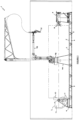
- a laser cladding system 1 including a machine bed or rail 2.
- a workpiece positioning system in the form of a headstock assembly 3 is securely fastened adjacent one end of the rail 2.
- a machine base in the form of a tailstock assembly 4 is slidably mounted to the other end of the rail 2 and in spaced apart relation relative to the headstock assembly 3 such that a workpiece (not shown) can be supported between the headstock assembly3 and the tailstock assembly 4.
- the rail 2 has an upper rail plate 5 with a planer surface on which the headstock assembly and tailstock assemblies (3, 4) are seated.
- the rail 2 includes a base plate 6 extending in parallel spaced apart relation underneath the upper rail plate 5.
- the upper rail plate 5 and base plate 6 are held apart by a pair of side edge members 7 extending longitudinally along and adjacent to respective sides of the plates (5, 6).
- Each side edge member 7 is preferably formed by an elongate metal channel and arranged inwardly of the associated edges of the upper rail plate to define a protruding lip or catch to which a complementary engaging potion of the tailstock assembly is engagable.
- a plurality of support elements in the form of adjustable feet 8 are arranged about the periphery of the rail 2.
- Each foot 8 has a ground engaging portion and is adjustable in height to facilitate levelling of the upper rail plate 5.
- the headstock assembly 3 is fixedly mounted to the rail 2 by a plurality of threaded bolts that threadingly engaging the rail such that a distance between the headstock 3 and tailstock 4 assemblies is set by selective movement of the tailstock assembly 4 along the rail 2 (i.e. towards or away from the headstock assembly).
- the headstock assembly 3 has a base 9 for bearing against the rail 2 and a carrier in the form of a chuck 10 mounted to the base 9 and adapted to support the workpiece, in use.
- the headstock assembly 3 has a support structure in the form of a pair of spaced apart posts 11 extending upwardly from the base 9 for supporting the chuck 10 therebetween at a predetermined height above the rail 2.
- the headstock assembly 3 is adapted to move the workpiece about two axes, with the chuck configured for rotation about a first axis ('X- axis or axis of rotation') and tilting movement about a second axis ('Z- or tilt axis') orthogonal to the first axis ('X').
- the headstock assembly 3 includes a first drive means for rotating the chuck 10 about the first axis (X').
- the first drive means is controllable to rotate the chuck 10 at a desired rotational speed (i.e. rpm) through continuous 360 degree revolutions, optionally clockwise or counter-clockwise about the first axis.
- the first drive means preferably includes an electric motor with a reduction gearbox (not shown).
- the first drive means is preferably configured to enable rotation of the chuck at rotational speeds of up to 50 rpm (approximately 5 rad.s -1 ).
- the headstock assembly 3 includes a drive housing 12 for housing the first drive means, whereby the chuck 10 and drive housing 12 move together and tilt about the second or tilt axis.
- the headstock assembly 3 includes a second drive means, including an electric motor and reduction gearbox (not shown), for tilting the chuck 10 about its tilt axis ('Z').
- the second drive means is arranged in a second drive housing (not shown) and configured to enable the chuck 10 to be tilted about its tilt axis through a range of 0 to 90 degrees relative to the longitudinal axis of the rail, as desired.
- the second drive means can hold the chuck 10 at a desired (fixed) tilt angle, thereby to enable the first drive means to rotate the chuck about its axis of rotation whilst tilted. It will be appreciated that, when the chuck 10 is tilted, the axis of rotation is tilted and at an angle relative to the rail.
- the ability to tilt and hold the chuck at a desired tilt angle is particularly advantageous for laser cladding components having irregular or complex surface profiles.
- the chuck 10 may be releasably mountable to the headstock assembly 3. Depending the sixe and configuration of the workpiece and/or the parameters of the cladding process, the chuck 10 mounted to the headstock assembly may be a three-jaw chuck or a four-jaw chuck.
- the headstock assembly 3 can be configured to have capacity for relatively light and/or heavy duty operation and for handling a range of workpiece sizes.
- the headstock assembly 3 may be adapted to handle workpieces having (a) a weight of up to 10,000kg or more, (b) a length of up to 5m or more, and/or (c) a diameter of up to 1,000mm or more.
- the tailstock assembly 4 includes a locking mechanism 15 selectively and manually operable between a locking position in which the tailstock assembly is lockable against the rail 2 in a desired position relative to the headstock, and an unlocked position in which the tailstock 4 assembly is adapted to freely traverse the rail 2.
- the tailstock assembly 3 has a base 16 with a base surface adapted to bear against the upper rail surface 5 of the rail 2 when the locking mechanism 15 is in the locking position.
- the tailstock assembly 3 has a support structure 17 extending upwardly from the base 16.
- the support structure 17 is configured to hold a centring unit in the form of a tail chuck 18 (e.g. 3- or 4-jaw chuck) in coaxial alignment with the chuck 10 of the headstock assembly 3.
- a centring unit in the form of a tail chuck 18 (e.g. 3- or 4-jaw chuck) in coaxial alignment with the chuck 10 of the headstock assembly 3.
- the reference to coaxial alignment between the chuck 10 and tail chuck 18 refers to the configuration when the carrier/chuck is at 0 degree tilt angle relative to the rail 2 and the axis of rotation ('X') is parallel with the longitudinal axis of the rail 2.
- the tail chuck 18 assists to support the distal end of the component or workpiece (i.e. the other end of the workpiece to that supported by the chuck of the headstock assembly).
- the base 16 of the tailstock assembly 4 includes a friction reducing element in the form of a set of four wheels 19.
- the wheels 19 are operatively associated with the locking mechanism 15. When the locking mechanism 15 is in the unlocked position, the wheels 19 can bear against (in engaging contact) the rail 2 to allow rolling movement of the tailstock assembly 4 relative to the rail 2 towards and away from the headstock assembly 3, as required.
- the set of wheels 19 include two front wheels mounted to a front shaft 20 and two rear wheels mounted to a rear shaft 21.
- the ends of the front and rear shafts (20, 21) are configured such that the front and rear wheels are eccentrically mounted to the respective shafts, with the centre of each wheel offset from the axis of rotation of the respective shaft. This eccentric mounting of the wheels on the shaft facilitates the movement of the wheels into and out of contact with the rail 2 upon rotation of the shaft.
- the locking mechanism 15 includes a selectively operable lever 22 arranged and configured to simultaneously rotate the front and rear shafts (20, 21) and thereby move the wheels 19 relative to the rail 2.
- the lever 22 When the lever 22 is in a first position corresponding to the locked position, the wheels 19 are moved out of contact with the rail 2 and the base 16 bears against the rail 2.
- the lever 22 When the lever 22 is in a second position corresponding to the locking position, the wheels 19 are moved into contact with the rail 2 to enable movement of the base 16 and thus the tailstock assembly 4 relative to the rail 2.
- the lever 22 of the locking mechanism 15 is pivotally mounted at its proximal end to the base 16 and operatively connected to the wheels 19 via one or more linkage arms 23.
- a first linkage arm 23 has one end connected to the lever 22 near or adjacent the pivot point 24 and another end connected to the front shaft 20 via a lug 25 fixedly attached to the front shaft 20.
- a second linkage arm 23 has one end connected to the lever 22 near or adjacent to the pivot point 24 and another end connected to the rear shaft 21 via a lug 26 fixedly attached to the rear shaft 21.
- the front and rear shafts (20, 21) are fixedly secured to the base 16 via shaft mounting blocks 27 (i.e. respective left and right blocks), with each shaft passing through respective holes formed in each block 27 and the respective ends of the shafts protruding from the blocks such that the wheels 19 are mounted outwardly of the shaft mounting blocks 27.
- shaft mounting blocks 27 i.e. respective left and right blocks
- each shaft passing through respective holes formed in each block 27 and the respective ends of the shafts protruding from the blocks such that the wheels 19 are mounted outwardly of the shaft mounting blocks 27.
- a cover member 28 is arranged over each wheel 19.
- Each cover member 28 has a cavity for at least partially receiving the associated wheel 19.
- Each cover member 28 is mountable to the respective shaft mounting block 27 at one point and engagable with the rail 2 at another point, thereby to enable the base of the tailstock to (slidably and upwardly) move relative to the rail 2 upon rotation of the eccentrically mounted wheels 19 via operation of the lever 22.
- each cover 28 has two openings for receiving a pair of corresponding guide pins 30 extending upwardly from the respective shaft mounting block 27 such that the upper end 29 is vertically spaced from the top of the mounting block 27 to enable the base 16 of the tailstock 4 to move upwardly relative to the rail 2 upon rotation of the eccentrically mounted wheels.
- the base 16 of the tailstock assembly 4 and the rail 2 include complementary connectors for locking the base relative to the rail. These connectors are in the form of spring loaded locking pins 32 associated with the base 16 and corresponding receiving formations in the form of holes 33 in the rail 2.
- the rail 2 preferably has a linear array of holes 33 formed along one or both side edges of the rail 2 such that upon sliding movement of the base 16 of the tailstock 4 along the rail, the pin will align with a hole at which point the spring force will propel the pin into the underlying hole 33.
- the pin 32 may be held against the action of the spring to allow movement of the tailstock 4 further along the rail 2, depending on the spacing required between the headstock and tailstock assemblies (3, 4).
- the lever 22 of the locking mechanism 15 is able to be manually released and the base 4 moved by a single operator.
- This configuration is particularly advantageous in situations where it is desirable that no lubricant is used on the rail or machine bed on which the base is positioned. This may occur, for example in laser cladding, where debris such as metal powder falls on the rail or bed during operation and needs to be swept off.
- the laser cladding system 1 includes a powder injection nozzle 35 for delivering a cladding (powder) material towards a surface of the workpiece.
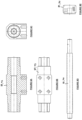
- the nozzle 35 includes an elongate hollow cylindrical body 36 and an elongate hollow cylindrical tube 37 coaxially and releasably arranged to extend through the body 36.
- the tube 37 is longer, and has a smaller diameter, compared to that of the body 36.
- the tube 37 has a constant cross-sectional diameter and defines a through passage with an inlet 38 for receiving the cladding material and an outlet 39 for delivering the cladding material.
- the body 36 has a gas inlet tube 40 for receiving a shielding gas and an outlet 41 for ejecting the gas from the body, thereby to form in use a gas shield about the cladding material as it is delivered from the body 36.
- the gas inlet tube 40 has a first free open 42 for connection to a gas supply line (not shown and second fixed end 43 fixed about a hole formed in a wall of the body 36, thereby to provide a passageway for the shielding gas from the first free end 42 to the interior of the body 36.
- the gas inlet tube 40 includes a first portion defining the first free end and extending parallel to the longitudinal axis of the body and a second portion extending at an angle of approximately 30 degrees relative to the first portion.
- the (gas) outlet 41 of the body 36 is formed by a ring insert 44 arranged at the distal end of the body 36 and between the body 36 and the central tube 37.
- the ring insert 44 has a polar array of eight holes 45 arranged about the tube 37 such that the gas can be delivered from the body and form a shield about cladding material as it exits the tube 37.
- the tube 37 passes through a central opening formed in the insert 44, preferably by way of an interference fit or size-for-size fit. It will be appreciated that the number, size and arrangement of the holes may vary to suit a particular application and is not limited to the exemplary arranged shown in the drawings.
- a closure member in the form of a collar 46 is sealingly arranged at the proximal end of the body 36 and between the body 36 and the tube 37 to prevent gas from escaping via the distal end of the body 36.
- the tube 37 passes through an opening formed in the collar 46, preferably by way of an interference fit or size-for-size fit.
- the interference or size-for-size fit between the tube 37 and the ring insert 44 and collar 46 advantageously provides and facilitates the releasable connection of the tube 37, allowing the tube 37 to be readily and efficiently removed and replaced as required.
- the tube 37 is fitted within the body 36 such that the outlet 39 projects from the distal end of the body 36, thereby to provide a nozzle tip 47.
- the nozzle tip 47 projects approximately 5mm forward of the distal end of the body 36.
- the inlet 38 of the tube 37 projects approximately 30-45mm rearwardly of the distal end of the body 36 to facilitate connection to a material feeder as described below.
- the powder injection nozzle 35 includes an integrally formed fluid delivery unit 50 for delivering a cooling fluid to the distal end region of the powder injection nozzle 35.
- the fluid delivery unit is in the form of a water cooling mechanism 50 adapted to control and cool the temperature of the distal end of the tube 37, nozzle tip 47 and body 36, in use.
- the water cooling mechanism 50 is particularly advantageous in laser cladding applications in which the nozzle tip 47 is required to be located in very close proximity to a laser beam and thus subject to extreme temperatures which can result in premature failure or reduced working life of the powder injection nozzle 35, particularly the nozzle tip 47.
- the water cooling mechanism 50 includes a sleeve 51 fixed to and bounding the distal end portion of the body 36, forming an enclosed area between an inner surface of the sleeve 51 and an outer surface or wall of the body 36.
- the length of the sleeve 51 is less than the length of the body 36.
- the sleeve 51 is preferably coaxially aligned with the body 36 such that a cross-sectional profile of the enclosed area is in the form of an annulus or ring.
- the sleeve 51 of the water cooling mechanism 50 includes an inlet hole 52 formed in the wall of the sleeve and through which water can be charged into the enclosed area between the sleeve and the body and circulated about the enclosed area, and a second outlet hole formed in the wall of the sleeve through which water can be discharged from the sleeve, thereby to cool the associated regions of the body, tube and nozzle tip in use.
- the water cooling mechanism 50 includes a water inlet pipe 52 having a first free open end 53 for connection (via a hose or other suitable duct) to a water supply line (not shown) and second fixed end 54 fixed about an inlet hole 55 formed in the wall of the sleeve 51, thereby to provide a passageway for water to be charged to the enclosed area.
- the water inlet pipe 52 includes a first portion defining the first free end and extending parallel to the longitudinal axis of the body and a second portion extending at an angle of approximately 30 degrees relative to the first portion.
- the water cooling mechanism 51 includes a water outlet pipe 56 having a first free open end 57 for connection (via a hose or other suitable duct) to a water waste or recycling station and second fixed end 58 fixed about an outlet hole 59 formed in the wall of the sleeve 51, thereby to provide a passageway for water to be discharged from the enclosed area.
- a nozzle mounting bracket 60 is provided to facilitate mounting of the powder injection nozzle 35 to a laser cladding assembly as described further below.
- the nozzle mounting bracket 60 is securely fixed connected to the body 36 so as to be positioned towards the proximal end of the body.
- the nozzle mounting bracket 60 has one or more receiving formations in the form of threaded holes for accommodating complementary fasteners to mount the nozzle in a predetermined desired position, in use.
- the body, the tube, the insert, the closure member, the gas inlet pipe, the water inlet and outlet pipes, and the nozzle mounting bracket are preferably formed of copper, with suitable copper welding a material between the respective parts.
- the inlet 38 of the tube 37 of the powder injection nozzle 35 is configured to be operatively connected to an outlet of a material feeder 65 adapted to deliver the cladding material to the tube 37.
- the material feeder 65 includes a powder tube 66 with an inlet for fluid communication with a source or reservoir of the cladding material and an outlet in fluid communication with the inlet of the tube 37 of the nozzle 35.
- the powder tube 66 is an elongate hollow cylindrical tube of constant cross-sectional diameter.
- the distal end of the powder tube 66 has a funnel 67 mounted thereto, the funnel defining the outlet of the material feeder 65.
- the inlet of the funnel 67 is sleevingly received over the outlet of the powder tube 66 and the funnel 67 tapers inwardly from its inlet 68 such that the inlet is wider than its outlet 69.
- the funnel 67 therefore has narrowed passageway which defines the outlet 69 through which the cladding material exits and passes to the tube 37 of the nozzle 35.
- the outlet 69 of the material feeder 65 is connected to the inlet 38 of the tube 37 of the nozzle 37 via a connecting mechanism such as for example a powder connection hose with associated connectors (e.g. quick release hose connectors) 70, as shown in Figure 4A .
- a connecting mechanism such as for example a powder connection hose with associated connectors (e.g. quick release hose connectors) 70, as shown in Figure 4A .
- the cladding material is preferably delivered to the inlet of the material feeder 65 as a cladding powder, preferably in a mixture with a pressurised carrier gas such as nitrogen.
- the rate of delivery of the cladding material is controlled prior to delivery to the material feeder 65, with the material source and carrier gas source each connected to the material feeder via a dedicated material source supply line and a dedicated carrier gas supply line, respectively.
- the powder tube 65 has a first inlet opening 71 for connection with the material source line through which the cladding material may pass into the tube 65, and a second inlet opening 72 for connection with the carrier gas source line through which the carrier gas may pass into the tube 65.
- the first and second inlet openings (71, 72) are formed a wall of the powder tube 65.
- a selectively operable control system (not shown) is associated with the powder source for controlling one or more delivery parameters (e.g. rate of delivery, pressure, duration, etc) under which the cladding material and the carrier fluid are delivered to the inlet of the material feeder 65.
- delivery parameters e.g. rate of delivery, pressure, duration, etc
- the delivery of cladding material through the powder tube and nozzle to the component by gravity feeding advantageously results is a substantially uniform delivery in terms of rate of delivery and quantity as well as facilitating a more even distribution of particles throughout the delivered material in the clad surface.
- a powder tube mounting bracket 73 is provided to facilitate mounting of the powder tube 65 to the laser cladding assembly.
- the powder tube mounting bracket 73 includes a square or rectangular plate adapted to be fastened to a desired mounting position or arm of the laser cladding system.
- the first plate has an opening 74 for at least partially receiving a nose portion 75 of the funnel 67.
- the nose portion 75 of the funnel 67 includes a boss 76 with an inwardly stepped distal end 77 to facilitate locating of the nose portion into the opening 74 of the first plate.
- the plate includes a threaded bore 78 in which a grub screw (not shown) can be threadingly engaged to lock and hold the funnel 67 in position against the plate 73.
- the mounting assembly includes a connecting element in the form of a generally L-shaped angle bracket 80.
- the bracket 80 has a first web 81 adapted to be secured to a laser assembly 82 (see Figure 4A ), and a second web 83 extending transversely from the first web 81 and configured to enable an adjusting assembly to be fastened thereto.
- the adjusting assembly includes a first adjustment mechanism 84 adapted to enable linear translational movement of the nozzle along a first axis.
- the first adjustment mechanism includes a rectangular prism shaped housing 85 connected by fasteners to the second web 83 of the bracket 80.
- the housing 80 has an internal bore or cavity 86 in which a first slide 87 is slidably arranged.
- the first slide 87 is operatively connected to an actuator in the formed of a threaded rod 88.
- the threaded rod 88 is threadingly engaged with the first slide 87 such that rotation of the rod 88 causes a corresponding linear translational movement of the first slide 87 relative to the housing 80 and thus a corresponding movement of the nozzle 35.
- a knob 89 is connected to an end of the rod 88 to facilitate manual operation of the first adjustment mechanism 84 (e.g. by hand rotation of the knob 89 in a clockwise or counter-clockwise direction).
- the adjusting assembly includes a second adjustment mechanism 90 operatively connected to the nozzle 35 and configured to enable selective movement of the nozzle relative to a laser beam projected by the laser assembly 82.
- the second adjustment mechanism 90 is adapted to enable linear translational movement of the nozzle 35 along a second axis extending transversely to the first axis (provided by the first adjustment mechanism 84).
- the second adjustment mechanism 90 includes a rectangular prism shaped housing 91 connected via a joining plate and fasteners to the first slide 87 of the first adjustment mechanism 84 such that the housing 91 of the second adjustment mechanism 90 is arranged to extend transversely to the housing 85 of the first adjustment mechanism 84.
- the housing 91 has an internal bore or cavity 92 in which a second slide 93 is slidably arranged.
- the second slide 93 is operatively connected to an actuator in the form of a threaded rod 94.
- the threaded rod 94 is threadingly enaged with the second slide such that rotation of the rod 94 causes a corresponding linear translational movement of the second slide 93 relative to the housing 91 and thus a corresponding movement of the nozzle 35.
- a knob 95 is connected to an end of the rod 94 to facilitate manual operation of the second adjustment mechanism 90 (e.g. by hand rotation of the knob 95 in a clockwise or counter-clockwise direction).
- a connecting arm 96 is connected to the second slide 93 of the second adjustment mechanism 90.
- the connecting arm 96 is adapted to carry the nozzle 35 and material feeder 65.
- the nozzle 35 is attached to the connecting arm 96 via the nozzle mounting bracket 60, and the material feeder 65 is attached to the connecting arm 96 via the powder tube mounting bracket 73.
- movement of the first slide 87 relative to the first housing 85 causes a corresponding movement of the second adjustment mechanism 90, connecting arm 96 and nozzle 35 in a first direction to allow positioning of the nozzle relative to the laser beam along a first axis.
- movement of the second slide 93 relative to the second housing 91 causes a corresponding movement of the connecting arm 96 and nozzle 35 in a second direction transverse to the first direction to allowing positioning of the nozzle 35 relative to the laser beam along a second axis.
- the connecting arm 96 is configured such that the powder injection nozzle 35 is arranged at a predetermined angle to the axis of the laser beam projected by the laser assembly 82, thereby to provide an off-axis delivery of the cladding material.
- the connecting arm 96 is bent to provide the desired relative angle between the nozzle and laser beam.
- the nozzle extends at an angle of approximately 20 degrees relative to the axis of the laser beam.
- the cladding material intersects the laser beam at a predetermined position (above) relative to the focal point of the laser beam.
- the laser cladding assembly includes an articulated robotic arm 97 with 6-degrees of freedom incorporating a support assembly for the laser assembly 82, whereby the robotic arm 97 is adapted to support the laser assembly 82 and nozzle 35/material feeder 65 as an end-effector of the arm or at an intermediate position along the arm.
- the robotic arm 97 includes a base 98 and a plurality of links 99 connected in series by a corresponding plurality of revolute joints, the links and joints thereby forming a kinematic chain terminating with the laser assembly and nozzle as the end-effector.
- Each of the revolute joints preferably incorporates an actuator, ideally in the form of an independently operable electric servo motor.
- the first and second adjustment mechanisms (84, 90) provide additional degrees of freedom in the kinematic chain, and additional operating range and/or fine adjustment for the robotic arm 97.
- the robotic arm 97 is mounted via its base 98 to a stand 100 which is slidably mounted to a second rail or bed (not shown) such that the robotic arm 97, laser assembly 82 and nozzle 35 can traverse the second rail in use to position the laser and nozzle relative to the workpiece or component, as required.
- the second rail is preferably arranged in parallel spaced apart relation relative to the rail 2 on which the headstock and tailstock assemblies (3, 4) are mounted. Linear sliding movement of the stand 100 along the second rail may be achieved by manual operation (e.g. pushed or pulled) or partly or fully automated by a suitable drive system, the control of which is undertaken as part of an overall control methodology for the laser cladding system.
- the invention in its various aspects and especially in its preferred embodiments provides a number of inherent and unique advantages.
- the invention was developed in part to improve the adaptability of a laser cladding system to be set up, customised and operated for use with workpieces of various and irregular shapes and sizes and, in various preferred embodiments, provides one or more of the following advantages in that context: a workpiece positioner with capacity to handle a wide range of workpieces from very small components to large jobs in excess of 10,000kg, >5m length, and/or >1000mm diameter, continuous infinite rotation of a workpiece about one axis at speeds of up to 50 rpm (approx.
- the laser cladding system is advantageously adapted to withstand high working temperatures and related heat transfer during the cladding process.
- the ability to withstand such high working temperatures is aided by the advantageous use of relatively large oil circulation gearboxes in the headstock, and relatively large radial and thrust bearings internal to both the headstock and tailstock.
- Preferred embodiments of the invention also advantageously provide a water cooled off-axis powder injection nozzle incorporating a rapidly replaceable powder injection tube.
- the ability to water cool the nozzle advantageously reduces the likelihood of melting of the tip of the nozzle tube, or at least extends its working life, by acting against direct or reflected laser energy, in use. It is particularly advantageous feature of the present invention that the nozzle tube can be readily and efficiently accessed and replaced, with advantages in terms of reduce downtime and labour costs.
- Preferred forms of the invention also advantageously provide a gravity fed powder injection nozzle by depressurising the powder transport system upstream of the nozzle, with related improvements in terms of accuracy and uniformity of delivery of the cladding powder material.
- the invention in its preferred forms also provides a simple, robust and accurate mechanism for adjusting the position of the powder injection nozzle with respect to the laser beam, as well as being largely resistant to cladding powder infiltration and heat.
- the invention also provides a machine base which in certain embodiments is readily operable by a single operator and adaptable for use in applications and machinery outside of laser cladding.
Landscapes
- Engineering & Computer Science (AREA)
- Physics & Mathematics (AREA)
- Optics & Photonics (AREA)
- Plasma & Fusion (AREA)
- Mechanical Engineering (AREA)
- Nozzles (AREA)
- Powder Metallurgy (AREA)
- Laser Beam Processing (AREA)
Claims (15)
- Eine Pulverspritzdüse (35) für ein Laserbeschichtungssystem (1), die Folgendes einschließt:einen länglichen hohlen zylindrischen Körper (36), wobei der Körper ein proximales Ende, ein distales Ende und einen Gaseinlass aufweist;eine längliche hohle zylindrische Röhre (37);dadurch gekennzeichnet, dass die Röhre (37) einen Außendurchmesser mit konstantem Querschnitt entlang ihrer Länge aufweist;wobei die Länge des Körpers (36) weniger als die Länge der Röhre ist (37);und dass ein Steckeinsatz (44) an dem distalen Ende des Körpers (36) angeordnet ist, wobei der Steckeinsatz (44) zwischen dem Körper (36) und der Röhre (37) lösbar angeordnet ist, wobei der Steckeinsatz (44) eine oder mehrere Öffnungen (45) aufweist, die einen Gasauslass (41) definieren, durch den ein Gas von dem Körper (36) geliefert werden kann;ein Verschlussglied (46) abdichtend an einem proximalen Ende des Körpers (36) angeordnet ist, wobei das Verschlussglied (46) zwischen dem Körper (36) und der Röhre (37) lösbar angeordnet ist, um zu verhindern, dass Gas über das proximale Ende des Körpers (36) entweicht;wobei der Steckeinsatz (44) eine zentrale Öffnung aufweist und das Verschlussglied (46) eine zentrale Öffnung aufweist, und wobei die Röhre (37) so konfiguriert ist, dass sie durch die zentrale Öffnung des Steckeinsatzes (44) und die zentrale Öffnung des Verschlussglieds (46) hindurch geht, sodass die Röhre (37) eine Presspassung oder eine Größe-für Größe-Passung mit dem Steckeinsatz (44) und dem Verschlussglied (46) aufweist, um dadurch eine lösbare Schiebeverbindung zwischen der Röhre (37) und sowohl dem Steckansatz (44) als auch dem Verschlussglied (46) bereitzustellen, wobei die Röhre (37) von den zentralen Öffnungen sowohl des Steckeinsatzes (44) als auch des Verschlussglieds (46) über die Schiebeverbindung montiert oder entfernt werden kann;wobei die Röhre (37) einen Durchgang definiert, der einen Einlass (38) zum Aufnehmen eines Beschichtungsmaterials und eine Düsenspitze (47), die einen Auslass (39) der Röhre (37) zum Liefern des Beschichtungsmaterials von der Röhre (37) definiert, aufweist;wobei die Röhre (37) in dem Körper (36), über die Presspassung oder die Größe-für Größe-Passung mit dem Steckeinsatz (44) und dem Verschlussglied (46), montiert ist, sodass ein distales Ende der Röhre (37) von dem distalen Ende des Körpers (36) nach vorne vorsteht, um die Düsenspitze (47) zu definieren;wobei die Röhre (37) in dem Körper (36), über die Presspassung oder die Größe-für Größe-Passung mit dem Steckeinsatz (44) und dem Verschlussglied (46), montiert ist, sodass sich ein proximales Ende der Röhre (37) von dem Körper (36) nach hinten erstreckt, wobei das Maß, in dem die Düsenspitze (47) von dem distalen Ende des Körpers (36) nach vorne vorsteht, weniger ist als das Maß, in dem sich das proximale Ende der Röhre (37) von dem Körper (36) nach hinten erstreckt; undwobei der Körper (36), die Röhre (37), der Steckeinsatz (44) und das Verschlussglied (46) allesamt aus demselben Material gebildet sind.
- Pulverspritzdüse (35) gemäß Anspruch 1, wobei der Gaseinlass eine Gaseinlassröhre (40) einschließt, die ein erstes freies offenes Ende (42) zur Verbindung mit einer Gasversorgungsleitung und ein zweites festes Ende (43), das sich durch ein in einer Wand des Körpers (36) gebildetes Loch erstreckt, aufweist, um dadurch einen Durchgang für das Gas von dem ersten freien Ende (42) zu einem Inneren des Körpers (36) bereitzustellen.
- Pulverspritzdüse (35) gemäß Anspruch 2, wobei die Gaseinlassröhre (40) Folgendes einschließt: einen ersten Abschnitt, der das erste freie Ende (42) definiert und sich parallel zu der Längsachse des Körpers (36) erstreckt, und einen zweiten Abschnitt, der sich in einem Winkel zu dem ersten Abschnitt erstreckt, wobei sich bevorzugt der zweite Abschnitt in einem Winkel im Bereich von 15 bis 50 Grad bezogen auf den ersten Abschnitt erstreckt.
- Pulverspritzdüse (35) gemäß Anspruch 2 oder Anspruch 3, wobei der Steckeinsatz (44) zwei oder mehr Öffnungen (45) einschließt, die angeordnet sind, um ein eine polare Gruppe von Öffnungen (45) um die Röhre (37) zu bilden, wobei bevorzugt jede Öffnung (45) einen Durchmesser von 1 mm oder weniger aufweist.
- Pulverspritzdüse (35) gemäß einem der vorhergehenden Ansprüche, wobei die Pulverspritzdüse (35) eine Fluidliefereinheit (50) zum Liefern eines Kühlfluids an die distale Endregion der Pulverspritzdüse (35) einschließt.
- Pulverspritzdüse (35) gemäß einem der vorhergehenden Ansprüche, wobei die Fluidliefereinheit einen Wasserkühlmechanismus einschließt, der angepasst ist, um die Temperatur des distalen Endes der Röhre (37) zu kühlen.
- Pulverspritzdüse (35) gemäß Anspruch 6, wobei der Wasserkühlmechanismus eine Hülse (51) einschließt, die mindestens an einem Abschnitt des Körpers (36) befestigt ist und diesen begrenzt, um dadurch einen umschlossenen Bereich zwischen einer Innenfläche der Hülse (51) und einer Außenfläche oder Wand des Körpers (36) zu bilden.
- Pulverspritzdüse gemäß Anspruch 7, wobei die Hülse (51) koaxial auf den Körper (36) ausgerichtet ist, die Hülse (51) angeordnet ist, um einen Abschnitt des Körpers (36) an oder neben dem distalen Ende des Körpers (36) zu begrenzen.
- Pulverspritzdüse (35) gemäß Anspruch 7 oder Anspruch 8, wobei die Hülse (51) des Wasserkühlmechanismus mindestens Folgendes umfasst: ein erstes Einlassloch (55), das in der Wand der Hülse (51) gebildet ist und durch das Wasser in den umschlossenen Bereich zwischen der Hülse (51) und dem Körper (36) eingeleitet und um den umschlossenen Bereich zirkuliert werden kann, und ein zweites Auslassloch, das in der Wand der Hülse (51) gebildet ist, durch das Wasser von der Hülse (51) abgeleitet werden kann, um dadurch die assoziierten Regionen des Körpers (36), der Röhre (37) und der Düsenspitze (47) bei Verwendung zu kühlen.
- Pulverspritzdüse (35) gemäß einem der Ansprüche 7 bis 9, wobei der Wasserkühlmechanismus ein Wassereinlassrohr (52) einschließt, das ein erstes freies offenes Ende (53) zur Verbindung mit einer Wasserversorgungsleitung und ein zweites festes Ende (54), das in dem oder um das erste Einlassloch (55), das in der Wand der Hülse (51) gebildet ist, fixiert ist, aufweist, um dadurch einen Durchgang für Wasser, das in den umschlossenen Bereich einzuleiten ist, bereitzustellen.
- Pulverspritzdüse (35) gemäß einem der Ansprüche 7 bis 10, wobei der Wasserkühlmechanismus ein Wasserauslassrohr (56) einschließt, das ein erstes freies offenes Ende (57) zur Verbindung mit einer Abwasser- oder Recyclingstation und ein zweites festes Ende (58), das in dem oder um das zweite Auslassloch (59), das in der Wand der Hülse (51) gebildet ist, fixiert ist, aufweist, um dadurch einen Durchgang für Wasser, das von dem umschlossenen Bereich abzuleiten ist, bereitzustellen.
- Pulverspritzdüse (35) gemäß einem der vorhergehenden Ansprüche, wobei der Körper (36), die Röhre (37), der Steckansatz (44) und das Verschlussglied (46) aus Kupfer gebildet sind.
- Pulverspritzdüse (35) gemäß einem der vorhergehenden Ansprüche, wobei der Einlass (38) der Röhre (37) der Pulverspritzdüse (35) so konfiguriert ist, dass er mit einem Auslass (69) eines Materialbeschickers (65) betriebsmäßig verbunden wird, der angepasst ist, um das Beschickungsmaterial an die Röhre (37) zu liefern.
- Pulverspritzdüse gemäß Anspruch 13, wobei der Materialbeschicker (65) eine Pulverröhre (66) mit einem Einlass zur Fluidkommunikation mit einer Quelle oder einem Reservoir des Beschichtungsmaterials und einem Auslass zur Fluidkommunikation mit dem Einlass der Röhre (37) der Düse (35) einschließt, und wobei bevorzugt die Lieferung des Beschichtungsmaterials an den Einlass des Beschickers druckbeaufschlagt ist.
- Pulverspritzdüse (35) gemäß einem der vorhergehenden Ansprüche, wobei ein selektiv betriebsfähiges Steuerungssystem mit der Quelle des Beschichtungsmaterials zum Steuern von einem oder mehreren Lieferparametern assoziiert ist, unter dem das Beschichtungsmaterial und das Trägerfluid an den Einlass des Materialbeschickers (65) geliefert werden, wobei bevorzugt das selektiv betriebsfähige Steuerungssystem so konfiguriert ist, dass es mindestens eines von der Rate, dem Druck und der Dauer der Lieferung des Beschichtungsmaterials und des Trägerfluids an den Einlass des Materialbeschickers (65) steuert.
Applications Claiming Priority (2)
| Application Number | Priority Date | Filing Date | Title |
|---|---|---|---|
| AU2017901140A AU2017901140A0 (en) | 2017-03-29 | Method, systems and assemblies for laser deposition | |
| PCT/AU2018/050297 WO2018176101A1 (en) | 2017-03-29 | 2018-03-29 | Methods, systems and assemblies for laser deposition |
Publications (4)
| Publication Number | Publication Date |
|---|---|
| EP3600754A1 EP3600754A1 (de) | 2020-02-05 |
| EP3600754A4 EP3600754A4 (de) | 2021-01-06 |
| EP3600754C0 EP3600754C0 (de) | 2025-05-21 |
| EP3600754B1 true EP3600754B1 (de) | 2025-05-21 |
Family
ID=63673930
Family Applications (1)
| Application Number | Title | Priority Date | Filing Date |
|---|---|---|---|
| EP18777171.2A Active EP3600754B1 (de) | 2017-03-29 | 2018-03-29 | Düse für eine laserbeschichtungsanornung |
Country Status (5)
| Country | Link |
|---|---|
| US (1) | US12128499B2 (de) |
| EP (1) | EP3600754B1 (de) |
| CN (1) | CN110831721A (de) |
| AU (1) | AU2018241250B2 (de) |
| WO (1) | WO2018176101A1 (de) |
Families Citing this family (2)
| Publication number | Priority date | Publication date | Assignee | Title |
|---|---|---|---|---|
| CN112695317A (zh) * | 2020-12-18 | 2021-04-23 | 重庆工商大学 | 激光熔覆加工用定位装置 |
| DE102022128180A1 (de) * | 2022-10-25 | 2024-04-25 | TRUMPF Werkzeugmaschinen SE + Co. KG | Medienzufuhr beim Laserschweißen |
Family Cites Families (33)
| Publication number | Priority date | Publication date | Assignee | Title |
|---|---|---|---|---|
| US4659901A (en) * | 1984-07-10 | 1987-04-21 | Westinghouse Electric Corp. | Particulate collection system for laser welding apparatus |
| GB8425716D0 (en) * | 1984-10-11 | 1984-11-14 | Quantum Laser Uk Ltd | Screw powder feeders |
| FR2575678B1 (fr) | 1985-01-04 | 1988-06-03 | Saint Gobain Vitrage | Ejecteur pneumatique de poudre |
| US4724299A (en) * | 1987-04-15 | 1988-02-09 | Quantum Laser Corporation | Laser spray nozzle and method |
| IL92428A (en) * | 1989-02-08 | 1992-12-01 | Gen Electric | Fabrication of components by layered deposition |
| US5304771A (en) * | 1992-02-18 | 1994-04-19 | D. A. Griffin Corporation | Apparatus for precisely metering powder for welding |
| US5453329A (en) * | 1992-06-08 | 1995-09-26 | Quantum Laser Corporation | Method for laser cladding thermally insulated abrasive particles to a substrate, and clad substrate formed thereby |
| US5477025A (en) * | 1994-01-14 | 1995-12-19 | Quantum Laser Corporation | Laser nozzle |
| US5486676A (en) * | 1994-11-14 | 1996-01-23 | General Electric Company | Coaxial single point powder feed nozzle |
| CN2257230Y (zh) * | 1996-01-30 | 1997-07-02 | 中国工程物理研究院核物理与化学研究所 | 激光喷焊送粉装置 |
| US6396025B1 (en) * | 1999-07-01 | 2002-05-28 | Aeromet Corporation | Powder feed nozzle for laser welding |
| CN2530769Y (zh) * | 2002-04-01 | 2003-01-15 | 李鲁伯 | 激光熔覆及合金化用送粉嘴空间位置调节装置 |
| US6601782B1 (en) * | 2002-12-23 | 2003-08-05 | Plas-Pak Industries, Inc. | Disposable spray nozzle assembly |
| US20050056628A1 (en) * | 2003-09-16 | 2005-03-17 | Yiping Hu | Coaxial nozzle design for laser cladding/welding process |
| US7038162B2 (en) * | 2003-11-13 | 2006-05-02 | Honeywell International, Inc. | Hand-held laser welding wand filler media delivery systems and methods |
| CN2707772Y (zh) * | 2004-06-15 | 2005-07-06 | 华南理工大学 | 环式同轴激光熔覆喷嘴 |
| EP1928631A4 (de) * | 2005-08-23 | 2009-08-05 | Hardwear Pty Ltd | Pulverzufuhrdüse |
| CN100408250C (zh) * | 2005-11-25 | 2008-08-06 | 北京工业大学 | 一种基于激光粉末填充焊接的旁轴送粉装置及送粉方法 |
| US20090291197A1 (en) * | 2008-05-21 | 2009-11-26 | Fraunhofer Usa | Laser cladding of tubes |
| US8297478B2 (en) * | 2008-09-30 | 2012-10-30 | Honeywell International Inc. | Powder feed cylinder assemblies and powder feeders |
| US20120199564A1 (en) * | 2011-02-09 | 2012-08-09 | Coherent, Inc. | Powder-delivery apparatus for laser-cladding |
| JP2013075308A (ja) * | 2011-09-30 | 2013-04-25 | Hitachi Ltd | パウダ供給ノズルおよび肉盛溶接方法 |
| CN103132072B (zh) * | 2013-03-20 | 2014-11-12 | 上海交通大学 | 一种激光熔覆用侧向送粉喷嘴装置 |
| CN203393228U (zh) | 2013-07-09 | 2014-01-15 | 南京煜宸激光科技有限公司 | 一种送粉头调节机构 |
| EP3049189B1 (de) * | 2013-09-25 | 2019-10-30 | United Technologies Corporation | Vereinfachte kaltsprühdüse und pistole |
| CN203878217U (zh) * | 2014-06-09 | 2014-10-15 | 江苏中科四象激光科技有限公司 | 一种带全水冷送粉嘴的激光熔覆头 |
| US9829031B2 (en) * | 2014-07-14 | 2017-11-28 | Nylok Llc | Apparatus and method for selectively applying powder coatings onto internally threaded fasteners |
| CN204172351U (zh) * | 2014-08-27 | 2015-02-25 | 三亚思海创新机电工程设计有限公司 | 3d打印机用打印头 |
| JP5969562B2 (ja) * | 2014-09-16 | 2016-08-17 | 株式会社東芝 | ノズル装置および積層造形装置 |
| GB2533102B (en) | 2014-12-09 | 2018-10-31 | Bae Systems Plc | Additive Manufacturing |
| CN107249811A (zh) | 2015-02-19 | 2017-10-13 | 三菱日立电力系统株式会社 | 焊接装置、焊接方法、及涡轮叶片 |
| WO2017011456A1 (en) * | 2015-07-16 | 2017-01-19 | Velo3D, Inc. | Material-fall three-dimensional printing |
| CN106435576A (zh) * | 2016-11-21 | 2017-02-22 | 华南师范大学 | 旁轴送粉喷嘴装置 |
-
2018
- 2018-03-29 AU AU2018241250A patent/AU2018241250B2/en active Active
- 2018-03-29 EP EP18777171.2A patent/EP3600754B1/de active Active
- 2018-03-29 WO PCT/AU2018/050297 patent/WO2018176101A1/en not_active Ceased
- 2018-03-29 US US16/498,970 patent/US12128499B2/en active Active
- 2018-03-29 CN CN201880035243.5A patent/CN110831721A/zh active Pending
Also Published As
| Publication number | Publication date |
|---|---|
| AU2018241250B2 (en) | 2024-04-11 |
| CN110831721A (zh) | 2020-02-21 |
| WO2018176101A1 (en) | 2018-10-04 |
| US20210086298A1 (en) | 2021-03-25 |
| EP3600754A1 (de) | 2020-02-05 |
| AU2018241250A1 (en) | 2019-11-21 |
| EP3600754C0 (de) | 2025-05-21 |
| US12128499B2 (en) | 2024-10-29 |
| EP3600754A4 (de) | 2021-01-06 |
Similar Documents
| Publication | Publication Date | Title |
|---|---|---|
| CN107429381B (zh) | 用于包覆物品的表面的方法和设备 | |
| US6316744B1 (en) | Machining head and process for the surface machining of workpieces by means of a laser beam | |
| JP4272999B2 (ja) | 手持ち式粉体供給レーザー融接トーチ | |
| US20060006157A1 (en) | Method and apparatus for repairing or building up surfaces on a workpiece while the workpiece is mounted on a machine tool | |
| KR19990083202A (ko) | 내부면의 레이저 가공 방법 및 장치 | |
| US8119950B2 (en) | Laser apparatus for hard surface coatings | |
| AU781334B2 (en) | Method for producing a surface-alloyed cylindrical, partially cylindrical or hollow cylindrical component and a device for carrying out said method | |
| US12257655B2 (en) | Vibrating welding apparatus and method | |
| AU2018241250B2 (en) | Methods, systems and assemblies for laser deposition | |
| CN111945100B (zh) | 一种惰性气体保护的仿可控气氛等离子喷涂方法及其装置 | |
| CA2651145A1 (en) | Welding guide nozzle including nozzle tip for precision weld wire positioning | |
| EP3481578B1 (de) | Flüssigkeitsgekühlte kontaktspitzenanordnung zum schweissen von metallen | |
| CN205324962U (zh) | 高校等离子堆焊机 | |
| CA3030044C (en) | Fluid-cooled contact tip assembly for metal welding | |
| EA041206B1 (ru) | Способ и устройство для плакирования поверхности изделия |
Legal Events
| Date | Code | Title | Description |
|---|---|---|---|
| STAA | Information on the status of an ep patent application or granted ep patent |
Free format text: STATUS: THE INTERNATIONAL PUBLICATION HAS BEEN MADE |
|
| PUAI | Public reference made under article 153(3) epc to a published international application that has entered the european phase |
Free format text: ORIGINAL CODE: 0009012 |
|
| STAA | Information on the status of an ep patent application or granted ep patent |
Free format text: STATUS: REQUEST FOR EXAMINATION WAS MADE |
|
| 17P | Request for examination filed |
Effective date: 20191029 |
|
| AK | Designated contracting states |
Kind code of ref document: A1 Designated state(s): AL AT BE BG CH CY CZ DE DK EE ES FI FR GB GR HR HU IE IS IT LI LT LU LV MC MK MT NL NO PL PT RO RS SE SI SK SM TR |
|
| AX | Request for extension of the european patent |
Extension state: BA ME |
|
| DAV | Request for validation of the european patent (deleted) | ||
| DAX | Request for extension of the european patent (deleted) | ||
| A4 | Supplementary search report drawn up and despatched |
Effective date: 20201208 |
|
| RIC1 | Information provided on ipc code assigned before grant |
Ipc: B23K 26/34 20140101ALI20201202BHEP Ipc: B23K 26/14 20140101AFI20201202BHEP Ipc: B05B 7/14 20060101ALI20201202BHEP |
|
| STAA | Information on the status of an ep patent application or granted ep patent |
Free format text: STATUS: EXAMINATION IS IN PROGRESS |
|
| 17Q | First examination report despatched |
Effective date: 20221116 |
|
| GRAP | Despatch of communication of intention to grant a patent |
Free format text: ORIGINAL CODE: EPIDOSNIGR1 |
|
| STAA | Information on the status of an ep patent application or granted ep patent |
Free format text: STATUS: GRANT OF PATENT IS INTENDED |
|
| INTG | Intention to grant announced |
Effective date: 20241213 |
|
| GRAS | Grant fee paid |
Free format text: ORIGINAL CODE: EPIDOSNIGR3 |
|
| GRAA | (expected) grant |
Free format text: ORIGINAL CODE: 0009210 |
|
| STAA | Information on the status of an ep patent application or granted ep patent |
Free format text: STATUS: THE PATENT HAS BEEN GRANTED |
|
| AK | Designated contracting states |
Kind code of ref document: B1 Designated state(s): AL AT BE BG CH CY CZ DE DK EE ES FI FR GB GR HR HU IE IS IT LI LT LU LV MC MK MT NL NO PL PT RO RS SE SI SK SM TR |
|
| REG | Reference to a national code |
Ref country code: GB Ref legal event code: FG4D |
|
| REG | Reference to a national code |
Ref country code: CH Ref legal event code: EP |
|
| REG | Reference to a national code |
Ref country code: DE Ref legal event code: R096 Ref document number: 602018082115 Country of ref document: DE |
|
| REG | Reference to a national code |
Ref country code: IE Ref legal event code: FG4D |
|
| U01 | Request for unitary effect filed |
Effective date: 20250617 |
|
| U07 | Unitary effect registered |
Designated state(s): AT BE BG DE DK EE FI FR IT LT LU LV MT NL PT RO SE SI Effective date: 20250627 |
|
| PG25 | Lapsed in a contracting state [announced via postgrant information from national office to epo] |
Ref country code: ES Free format text: LAPSE BECAUSE OF FAILURE TO SUBMIT A TRANSLATION OF THE DESCRIPTION OR TO PAY THE FEE WITHIN THE PRESCRIBED TIME-LIMIT Effective date: 20250521 |
|
| PG25 | Lapsed in a contracting state [announced via postgrant information from national office to epo] |
Ref country code: NO Free format text: LAPSE BECAUSE OF FAILURE TO SUBMIT A TRANSLATION OF THE DESCRIPTION OR TO PAY THE FEE WITHIN THE PRESCRIBED TIME-LIMIT Effective date: 20250821 Ref country code: GR Free format text: LAPSE BECAUSE OF FAILURE TO SUBMIT A TRANSLATION OF THE DESCRIPTION OR TO PAY THE FEE WITHIN THE PRESCRIBED TIME-LIMIT Effective date: 20250822 |
|
| PG25 | Lapsed in a contracting state [announced via postgrant information from national office to epo] |
Ref country code: PL Free format text: LAPSE BECAUSE OF FAILURE TO SUBMIT A TRANSLATION OF THE DESCRIPTION OR TO PAY THE FEE WITHIN THE PRESCRIBED TIME-LIMIT Effective date: 20250521 |
|
| PG25 | Lapsed in a contracting state [announced via postgrant information from national office to epo] |
Ref country code: HR Free format text: LAPSE BECAUSE OF FAILURE TO SUBMIT A TRANSLATION OF THE DESCRIPTION OR TO PAY THE FEE WITHIN THE PRESCRIBED TIME-LIMIT Effective date: 20250521 |
|
| PG25 | Lapsed in a contracting state [announced via postgrant information from national office to epo] |
Ref country code: RS Free format text: LAPSE BECAUSE OF FAILURE TO SUBMIT A TRANSLATION OF THE DESCRIPTION OR TO PAY THE FEE WITHIN THE PRESCRIBED TIME-LIMIT Effective date: 20250821 |
|
| PG25 | Lapsed in a contracting state [announced via postgrant information from national office to epo] |
Ref country code: IS Free format text: LAPSE BECAUSE OF FAILURE TO SUBMIT A TRANSLATION OF THE DESCRIPTION OR TO PAY THE FEE WITHIN THE PRESCRIBED TIME-LIMIT Effective date: 20250921 |
|
| PG25 | Lapsed in a contracting state [announced via postgrant information from national office to epo] |
Ref country code: SM Free format text: LAPSE BECAUSE OF FAILURE TO SUBMIT A TRANSLATION OF THE DESCRIPTION OR TO PAY THE FEE WITHIN THE PRESCRIBED TIME-LIMIT Effective date: 20250521 |
|
| PG25 | Lapsed in a contracting state [announced via postgrant information from national office to epo] |
Ref country code: CZ Free format text: LAPSE BECAUSE OF FAILURE TO SUBMIT A TRANSLATION OF THE DESCRIPTION OR TO PAY THE FEE WITHIN THE PRESCRIBED TIME-LIMIT Effective date: 20250521 |
|
| PG25 | Lapsed in a contracting state [announced via postgrant information from national office to epo] |
Ref country code: SK Free format text: LAPSE BECAUSE OF FAILURE TO SUBMIT A TRANSLATION OF THE DESCRIPTION OR TO PAY THE FEE WITHIN THE PRESCRIBED TIME-LIMIT Effective date: 20250521 |
|
| U20 | Renewal fee for the european patent with unitary effect paid |
Year of fee payment: 9 Effective date: 20260209 |
|
| PLBE | No opposition filed within time limit |
Free format text: ORIGINAL CODE: 0009261 |
|
| STAA | Information on the status of an ep patent application or granted ep patent |
Free format text: STATUS: NO OPPOSITION FILED WITHIN TIME LIMIT |
|
| REG | Reference to a national code |
Ref country code: CH Ref legal event code: U11 Free format text: ST27 STATUS EVENT CODE: U-0-0-U10-U11 (AS PROVIDED BY THE NATIONAL OFFICE) Effective date: 20260401 |
|
| REG | Reference to a national code |
Ref country code: CH Ref legal event code: L10 Free format text: ST27 STATUS EVENT CODE: U-0-0-L10-L00 (AS PROVIDED BY THE NATIONAL OFFICE) Effective date: 20260402 |
|
| PGFP | Annual fee paid to national office [announced via postgrant information from national office to epo] |
Ref country code: GB Payment date: 20260209 Year of fee payment: 9 |
|
| 26N | No opposition filed |
Effective date: 20260224 |