EP3600808B1 - System zum applizieren eines baustoffes - Google Patents
System zum applizieren eines baustoffes Download PDFInfo
- Publication number
- EP3600808B1 EP3600808B1 EP18749396.0A EP18749396A EP3600808B1 EP 3600808 B1 EP3600808 B1 EP 3600808B1 EP 18749396 A EP18749396 A EP 18749396A EP 3600808 B1 EP3600808 B1 EP 3600808B1
- Authority
- EP
- European Patent Office
- Prior art keywords
- building material
- fibres
- fibers
- conveying device
- windings
- Prior art date
- Legal status (The legal status is an assumption and is not a legal conclusion. Google has not performed a legal analysis and makes no representation as to the accuracy of the status listed.)
- Active
Links
Images



Classifications
-
- B—PERFORMING OPERATIONS; TRANSPORTING
- B28—WORKING CEMENT, CLAY, OR STONE
- B28B—SHAPING CLAY OR OTHER CERAMIC COMPOSITIONS; SHAPING SLAG; SHAPING MIXTURES CONTAINING CEMENTITIOUS MATERIAL, e.g. PLASTER
- B28B1/00—Producing shaped prefabricated articles from the material
- B28B1/001—Rapid manufacturing of 3D objects by additive depositing, agglomerating or laminating of material
-
- B—PERFORMING OPERATIONS; TRANSPORTING
- B01—PHYSICAL OR CHEMICAL PROCESSES OR APPARATUS IN GENERAL
- B01F—MIXING, e.g. DISSOLVING, EMULSIFYING OR DISPERSING
- B01F27/00—Mixers with rotary stirring devices in fixed receptacles; Kneaders
- B01F27/05—Stirrers
- B01F27/07—Stirrers characterised by their mounting on the shaft
- B01F27/071—Fixing of the stirrer to the shaft
-
- B—PERFORMING OPERATIONS; TRANSPORTING
- B01—PHYSICAL OR CHEMICAL PROCESSES OR APPARATUS IN GENERAL
- B01F—MIXING, e.g. DISSOLVING, EMULSIFYING OR DISPERSING
- B01F27/00—Mixers with rotary stirring devices in fixed receptacles; Kneaders
- B01F27/05—Stirrers
- B01F27/11—Stirrers characterised by the configuration of the stirrers
- B01F27/19—Stirrers with two or more mixing elements mounted in sequence on the same axis
- B01F27/192—Stirrers with two or more mixing elements mounted in sequence on the same axis with dissimilar elements
- B01F27/1921—Stirrers with two or more mixing elements mounted in sequence on the same axis with dissimilar elements comprising helical elements and paddles
-
- B—PERFORMING OPERATIONS; TRANSPORTING
- B01—PHYSICAL OR CHEMICAL PROCESSES OR APPARATUS IN GENERAL
- B01F—MIXING, e.g. DISSOLVING, EMULSIFYING OR DISPERSING
- B01F27/00—Mixers with rotary stirring devices in fixed receptacles; Kneaders
- B01F27/21—Mixers with rotary stirring devices in fixed receptacles; Kneaders characterised by their rotating shafts
- B01F27/2123—Shafts with both stirring means and feeding or discharging means
-
- B—PERFORMING OPERATIONS; TRANSPORTING
- B01—PHYSICAL OR CHEMICAL PROCESSES OR APPARATUS IN GENERAL
- B01F—MIXING, e.g. DISSOLVING, EMULSIFYING OR DISPERSING
- B01F33/00—Other mixers; Mixing plants; Combinations of mixers
- B01F33/50—Movable or transportable mixing devices or plants
- B01F33/501—Movable mixing devices, i.e. readily shifted or displaced from one place to another, e.g. portable during use
- B01F33/5013—Movable mixing devices, i.e. readily shifted or displaced from one place to another, e.g. portable during use movable by mechanical means, e.g. hoisting systems, grippers or lift trucks
-
- B—PERFORMING OPERATIONS; TRANSPORTING
- B28—WORKING CEMENT, CLAY, OR STONE
- B28C—PREPARING CLAY; PRODUCING MIXTURES CONTAINING CLAY OR CEMENTITIOUS MATERIAL, e.g. PLASTER
- B28C5/00—Apparatus or methods for producing mixtures of cement with other substances, e.g. slurries, mortars, porous or fibrous compositions
- B28C5/40—Mixing specially adapted for preparing mixtures containing fibres
-
- B—PERFORMING OPERATIONS; TRANSPORTING
- B33—ADDITIVE MANUFACTURING TECHNOLOGY
- B33Y—ADDITIVE MANUFACTURING, i.e. MANUFACTURING OF THREE-DIMENSIONAL [3D] OBJECTS BY ADDITIVE DEPOSITION, ADDITIVE AGGLOMERATION OR ADDITIVE LAYERING, e.g. BY 3D PRINTING, STEREOLITHOGRAPHY OR SELECTIVE LASER SINTERING
- B33Y10/00—Processes of additive manufacturing
-
- B—PERFORMING OPERATIONS; TRANSPORTING
- B33—ADDITIVE MANUFACTURING TECHNOLOGY
- B33Y—ADDITIVE MANUFACTURING, i.e. MANUFACTURING OF THREE-DIMENSIONAL [3D] OBJECTS BY ADDITIVE DEPOSITION, ADDITIVE AGGLOMERATION OR ADDITIVE LAYERING, e.g. BY 3D PRINTING, STEREOLITHOGRAPHY OR SELECTIVE LASER SINTERING
- B33Y30/00—Apparatus for additive manufacturing; Details thereof or accessories therefor
-
- B—PERFORMING OPERATIONS; TRANSPORTING
- B01—PHYSICAL OR CHEMICAL PROCESSES OR APPARATUS IN GENERAL
- B01F—MIXING, e.g. DISSOLVING, EMULSIFYING OR DISPERSING
- B01F27/00—Mixers with rotary stirring devices in fixed receptacles; Kneaders
- B01F27/05—Stirrers
- B01F27/11—Stirrers characterised by the configuration of the stirrers
- B01F27/112—Stirrers characterised by the configuration of the stirrers with arms, paddles, vanes or blades
- B01F27/1121—Stirrers characterised by the configuration of the stirrers with arms, paddles, vanes or blades pin-shaped
-
- B—PERFORMING OPERATIONS; TRANSPORTING
- B28—WORKING CEMENT, CLAY, OR STONE
- B28C—PREPARING CLAY; PRODUCING MIXTURES CONTAINING CLAY OR CEMENTITIOUS MATERIAL, e.g. PLASTER
- B28C5/00—Apparatus or methods for producing mixtures of cement with other substances, e.g. slurries, mortars, porous or fibrous compositions
- B28C5/02—Apparatus or methods for producing mixtures of cement with other substances, e.g. slurries, mortars, porous or fibrous compositions without using driven mechanical means effecting the mixing
- B28C5/026—Mixing guns or nozzles; Injector mixers
-
- B—PERFORMING OPERATIONS; TRANSPORTING
- B28—WORKING CEMENT, CLAY, OR STONE
- B28C—PREPARING CLAY; PRODUCING MIXTURES CONTAINING CLAY OR CEMENTITIOUS MATERIAL, e.g. PLASTER
- B28C5/00—Apparatus or methods for producing mixtures of cement with other substances, e.g. slurries, mortars, porous or fibrous compositions
- B28C5/08—Apparatus or methods for producing mixtures of cement with other substances, e.g. slurries, mortars, porous or fibrous compositions using driven mechanical means affecting the mixing
- B28C5/0893—Mobile mixing devices, e.g. hanging
-
- B—PERFORMING OPERATIONS; TRANSPORTING
- B28—WORKING CEMENT, CLAY, OR STONE
- B28C—PREPARING CLAY; PRODUCING MIXTURES CONTAINING CLAY OR CEMENTITIOUS MATERIAL, e.g. PLASTER
- B28C5/00—Apparatus or methods for producing mixtures of cement with other substances, e.g. slurries, mortars, porous or fibrous compositions
- B28C5/08—Apparatus or methods for producing mixtures of cement with other substances, e.g. slurries, mortars, porous or fibrous compositions using driven mechanical means affecting the mixing
- B28C5/10—Mixing in containers not actuated to effect the mixing
- B28C5/12—Mixing in containers not actuated to effect the mixing with stirrers sweeping through the materials, e.g. with incorporated feeding or discharging means or with oscillating stirrers
- B28C5/1238—Mixing in containers not actuated to effect the mixing with stirrers sweeping through the materials, e.g. with incorporated feeding or discharging means or with oscillating stirrers for materials flowing continuously through the mixing device and with incorporated feeding or discharging devices
- B28C5/1292—Mixing in containers not actuated to effect the mixing with stirrers sweeping through the materials, e.g. with incorporated feeding or discharging means or with oscillating stirrers for materials flowing continuously through the mixing device and with incorporated feeding or discharging devices with rotating stirring and feeding or discharging means fixed on the same axis, e.g. in an inclined container fed at its lower part
-
- B—PERFORMING OPERATIONS; TRANSPORTING
- B28—WORKING CEMENT, CLAY, OR STONE
- B28C—PREPARING CLAY; PRODUCING MIXTURES CONTAINING CLAY OR CEMENTITIOUS MATERIAL, e.g. PLASTER
- B28C5/00—Apparatus or methods for producing mixtures of cement with other substances, e.g. slurries, mortars, porous or fibrous compositions
- B28C5/08—Apparatus or methods for producing mixtures of cement with other substances, e.g. slurries, mortars, porous or fibrous compositions using driven mechanical means affecting the mixing
- B28C5/10—Mixing in containers not actuated to effect the mixing
- B28C5/12—Mixing in containers not actuated to effect the mixing with stirrers sweeping through the materials, e.g. with incorporated feeding or discharging means or with oscillating stirrers
- B28C5/14—Mixing in containers not actuated to effect the mixing with stirrers sweeping through the materials, e.g. with incorporated feeding or discharging means or with oscillating stirrers the stirrers having motion about a horizontal or substantially horizontal axis
- B28C5/148—Mixing in containers not actuated to effect the mixing with stirrers sweeping through the materials, e.g. with incorporated feeding or discharging means or with oscillating stirrers the stirrers having motion about a horizontal or substantially horizontal axis the stirrer shaft carrying a plurality of radially extending mixing bars
Definitions
- the present invention relates to a system for applying a building material.
- a known system for applying building materials is, for example, in WO 2013/064826 A1 described.
- a free-flowing building material is applied using a crane-like arm in order to create structures from the building material.
- the building material in this case a cementitious material, is stored in a reservoir and applied from there via a nozzle.
- the reservoir is filled up by a pump via a hose.
- a disadvantage of such a system is that there is no constant flow of building material available because the reservoir has to be refilled each time.
- US4039169 a system for applying a building material according to the preamble of claim 1 is known. More in particular is out US4039169 a sand mixer with a movable arm is known. Several mixing drums can be connected in series.
- One object of the present invention is to provide a system for applying a building material which allows the building material to be applied continuously.
- the system should be able to be adapted to different building materials in a simple and cost-effective manner.
- the building material is a multi-component composition based on plastic.
- the first component typically comprises a reactive polymer or monomer and the second component comprises a curing agent or accelerator for the crosslinking or curing of this polymer or monomer.
- such compositions are epoxy resins, polyurethanes, silane functional polymers, silicones, acrylates, and the like.
- the system is now adapted to building materials that contain fibers.
- a distance between adjacent windings of the conveyor screw is at least 40% of the length of the fibers and/or a distance between adjacent stirring elements of the stirring shaft is at least 40% of a length of the fibers.
- a first advantage of building materials with fibers is that the fibers can be used to create structures with increased flexural strength. Structures made of building materials with fibers break less quickly than building materials without fibers, and fibers continue to hold pieces of the building material that have already broken together, so that the structure remains essentially intact even if it breaks.
- another advantage of building materials with fibers can be that the fibers are able to connect adjacent layers, which are superimposed by the system, to one another. This increases the stability of the structure produced from building material.
- the conveying device is now adapted to the length of the fibers. It has been shown that adjacent windings of the conveyor screw should be at least 40% of the length of the fibers in order to effectively prevent blockages caused by clogged fibers in the conveyor device. A similar effect was observed with the stirring elements of the stirring shaft. Here, too, it is advantageous to space adjacent stirring elements from one another in such a way that a distance between adjacent stirring elements is at least 40% of the length of the fibers. These measures can ensure trouble-free use of the system proposed here for applying a building material with fibers.
- stirring devices or conveying devices in which the fibers can get stuck, tend to block the building material. It is therefore a core idea of the present invention, when using building materials with fibers, to design such conveying devices and stirring devices in such a way that the fibers cannot become wedged in them. This is achieved in particular by appropriate spacing of adjacent windings of the screw conveyor or by appropriate spacing of adjacent stirring elements of the stirring device.
- a distance between adjacent windings of the screw conveyor is at least 60% of the length of the fibers and/or a distance between adjacent stirring elements of the stirring shaft is at least 60% of a length of the fibers.
- a distance between adjacent windings of the conveyor screw is at least 80% of the length of the fibers and/or a distance between adjacent stirring elements of the stirring shaft is at least 80% of a length of the fibers
- the system is adapted to building materials that do not contain fibers.
- the distances between adjacent windings of the conveyor screw are smaller the closer the windings are arranged to an outlet, and/or a distance between adjacent stirring elements of the stirring shaft is from 5 to 50 mm, preferably from 7 to 40 mm, particularly preferably from 10 to 13 mm.
- stirring elements at said distances leads to a homogeneous mixture of building materials.
- the provision of generally more stirring elements compared to the use for building materials with fibers results in a higher energy input from the mixer into the building material, which is advantageous for the breakdown of the components of the building material and for the reaction of the first and the second component of the building material affect each other.
- a higher energy input from the mixer into the building material also has the advantage that the building material is brought to a higher temperature, which in turn causes the building material to solidify more quickly after it has left the system.
- a core idea of the present invention is that for applications without fibers, the conveying device and the stirring device can be optimized in such a way that the building material is conveyed out of the system with a certain pressure and/or that the components of the building material work together with an optimized energy input of the mixer be mixed. Because no fibers are included in this embodiment, the entire system is less prone to blockages.
- the system is adapted to a diameter of the grains of an aggregate of the first component of the building material. It was observed that in particular a distance between the stirring elements of the stirring shaft and an inner wall of the mixing chamber can be optimized with regard to a diameter of the grains of the aggregate. A similar situation was observed for a distance between the outer surfaces of the spirals of the conveyor and the inner wall of the mixing chamber. It has been shown that these distances between the stirring elements of the stirring device or the outer surfaces of the windings of the conveying device and the mixing chamber should be chosen to be at least as large as a diameter of the grains of the aggregate.
- a distance between the ends of stirring elements of the stirring shaft and/or outer surfaces of the windings of the conveying device and an inner wall of the mixing chamber is at least as large as a diameter of the grains of the aggregate.
- a core idea of the present invention with regard to the adaptation of the system with regard to the size of the aggregate is that the distances between the rotating elements and the inner wall of the mixing chamber can be adapted to the size of the aggregate.
- rock grains of the building material can get stuck between the rotating elements and the drum of the mixing chamber.
- jamming leads to increased wear of the corresponding elements and, on the other hand, can block the system. It is therefore advantageous to choose the specified distances at least as large as the diameter of the aggregate of the building material.
- the diameter of the grains of the aggregate is understood to be a mean, largest diameter of the aggregate of the building material.
- the invention is based on the finding that the rotating components of the mixing or conveying device of the system for applying the building material can be optimized with regard to the composition of the building material.
- the distances between the turns of the conveying device, the distances between the stirring elements of the stirring device and the distances between the rotating elements and the inner wall of the mixing chamber can be adapted to the components of the building material.
- Such an adjustment has the advantage that a constant operation of the system can be guaranteed without blockages of the building material occurring in the system, while at the same time a mixture of the components and a discharge through the conveying device can be optimized.
- a first turn of the auger has a smaller diameter than subsequent turns.
- the first flight of the auger has an outer surface that is beveled at an angle ⁇ such that a first edge is lower than a second edge.
- the first edge is spaced farther from the second turn than the second edge.
- the angle ⁇ is between 10° and 50°, particularly preferably between 15° and 45°, particularly preferably between 20° and 40°.
- the stirring elements have external threads and the stirring shaft has indentations with internal threads, so that the stirring elements can be inserted into and removed from the stirring shaft by rotation.
- Such a mechanism for inserting or removing the stirring elements from the stirring shaft has the advantage that the mixer can be easily adapted to the building material used.
- fewer stirring elements are used for building materials with fibers than for building materials without fibers.
- stirring elements can be exchanged in a simple manner as wearing parts by means of such a mechanism.
- between 30 and 70%, preferably between 35 and 65%, particularly preferably between 40 and 60% of the stirring elements are used for building materials with fibers compared to the number of stirring elements for building materials without fibers.
- the stirring elements are designed as pins.
- the building material contains fibers and spacings between adjacent turns are substantially equal.
- the building material contains fibers and spacings between turns of the conveyor are smaller the closer the turns are located to an outlet, the smallest spacing between adjacent turns being at least 40% of a length of the fibres.
- the building material has fibers and the conveyor has two to four turns.
- a cross section of a boundary surface of the conveying device is essentially straight or essentially S-shaped.
- the configuration of the cross section of the boundary surface can be used to influence a pressure with which the building material is conveyed out of the conveying device.
- the spacing of the windings also plays a role.
- the conveying device can be optimized in such a way that, on the one hand, a desired pressure can be built up and, on the other hand, a blockage by the building material can be prevented, in particular in the case of building materials which contain fibers.
- the building material contains fibers, the fibers having a length of 5 to 20 mm, preferably 7 to 17 mm, particularly preferably 10 to 15 mm, and the fibers preferably having a width of 5 to 2000 ⁇ m from 20 to 1000 ⁇ m, particularly preferably from 30 to 500 ⁇ m, and the fibers have a height of from 5 to 200 ⁇ m, preferably from 10 to 150 ⁇ m, particularly preferably from 30 to 100 ⁇ m.
- fibers dimensioned in this way are particularly suitable for increasing the flexural strength of a structure made from the building material and, on the other hand, can be guided through the mixer without blocking it.
- the building material contains fibers, the fibers consisting at least partially of metal or of glass or of carbon or of plastic or of natural fibers.
- the fibers consist at least partially of steel, in particular stainless steel.
- the fibers consist at least partially of PVA.
- Preferred fibers are selected from the group consisting of metal fibers, in particular steel fibers or amorphous metal fibers, mineral fibers, in particular glass fibers, basalt fibers or wollastonite fibers, natural fibers, in particular cellulose fibers, hemp fibers, linen fibers or silk fibers, and plastic fibers, in particular carbon fibers, polypropylene fibers , polyethylene, polyvinyl alcohol, polyamide, polyaramide, polyacrylonitrile or polyester, and mixtures thereof, metal fibers, carbon fibers, fibers made of polypropylene or fibers made of polyvinyl alcohol, or mixtures thereof, being particularly preferred.
- the building material contains fibers, the fibers being flexible.
- a height of the fibers is selected as a function of the material of the fibers in such a way that the fibers are bendable.
- the building material contains fibers, with 1 liter of building material between 1,000 and 1,000,000,000, preferably between 5,000 and 500,000,000, particularly preferably between 10,000 and 100,000,000 contains fibers.
- fibers can be used per liter of building material. For example, several hundred million very small carbon fibers can be used, or only a few thousand much larger steel fibers.
- the building material contains no fibers, with the conveying device having two to ten, preferably three to eight, particularly preferably four to six turns.
- the conveyor device is constructed at least partially from plastic.
- the conveying device is constructed at least partially from nylon.
- the conveying device is produced using a 3D printing process.
- the conveying device is constructed at least partially from metal, for example steel.
- the conveying device is arranged on the agitator shaft and is operatively connected to it, with the conveying device being designed to be removable from the agitator shaft.
- the conveying device is slipped onto the agitator shaft and secured to the agitator shaft by a locking element.
- the object set at the outset is also achieved by a method for producing a structure from a building material, the method comprising: providing a first component of the building material, comprising a pumpable concrete which contains an aggregate; Providing a second component of the building material, comprising a concrete admixture which contains a setting accelerator; Mixing the first component and the second component in a mixer, the mixer comprising a drive and a mixing chamber with an agitator shaft and a conveyor device, the conveyor device being designed as a conveyor screw with windings; Moving a moving device to change an application site in a room; Conveying the building material through the conveying element; application of the building material; and adapting the mixer to the building material.
- the mixer is adapted to the respective building material in the same way as has already been described for the system for applying the building material.
- the movement device is designed to be movable in the manner of a 3D printer, so that the system or the method can be used to build a wide variety of structures from the building material.
- Such systems in the form of 3D printers offer the advantage that entire structures can be produced from building material, such as building walls or the like. In this case, no formwork is necessary, and therefore the shape of the structure can also be selected much more freely than is the case with conventional systems or methods.
- the mixer is operated during mixing at a speed of more than 500 revolutions per minute, preferably at a speed of more than 650 revolutions per minute, particularly preferably at a speed of more than 800 revolutions per minute, particularly preferably at one Speed of more than 1000 revolutions per minute.
- pumpable concrete was mixed with a setting accelerator at speeds between 200 and 2000 revolutions per minute. It was found that when mixing at speeds below 500 revolutions per minute, a sufficiently homogeneous or smooth mixture is not achieved, so that the pumpable concrete or the pumpable accelerator mix insufficiently with one another. This led to solidification behavior that was difficult to control, since the insufficiently homogeneous mixture had areas with an above-average amount of solidification accelerator and areas with correspondingly too little solidification accelerator. This can also lead to blockages in the mixer and/or imperfections in the applied mixture, such as areas with insufficient strength after a certain time after leaving the mixer.
- the building material when applying the building material, is applied in a plurality of layers lying at least partially on top of one another.
- a new layer of the building material is only superimposed on an existing layer during application when the existing layer has sufficient strength to retain its original shape.
- At least partially overlapping layers of the building material are continuously built up during application, so that the structure can be built up from building material in the manner of a 3D print.
- the system 1 comprises a movement device 2, which in this exemplary embodiment is designed as a device with a crane-like arm.
- a mixer 5 is arranged at a head of the moving device 2 .
- a first component 3 and a second component 4 can each be fed to the mixer 5 via a first hose 27 and a second hose 28 .
- the mixer 5 has a first inlet 7.1 and a second inlet 7.2, at which the first component 3 and the second component 4 can be fed to the mixer 5.
- the mixer 5 also has an outlet 6 through which the building material can be applied.
- the mixer 5 is in each case moved by the moving device 2 to a location at which the building material is to be applied.
- the mixer 5 is off 1 shown in more detail.
- the mixer 5 has a drive 8 and a mixing chamber 9.
- the mixing chamber 9 has a first inlet 7.1, a second inlet 7.2 and a third inlet 7.3.
- the mixing chamber 9 has an outlet 6.
- the first inlet 7.1 can be used for feeding the first component
- the second inlet 7.2 can be used for feeding cleaning liquid into the mixing chamber 9
- the third inlet 7.3 can be used for the Feeding the second component of the building material into the mixing chamber 9 are used.
- a nozzle (not shown), for example, can be arranged at the outlet 6 in order to apply the building material in a desired cross section.
- an agitator shaft 16 is arranged in the mixing chamber 9 which on the one hand stirring elements 19 and a conveying element 18 is arranged.
- the stirring elements 19 are arranged on a first section of the stirring shaft 16 and the conveying device 18 is arranged on a second section of the stirring shaft 16 .
- the first section of the stirring shaft with the stirring elements 19 is arranged in the area of the inlets 7.1, 7.2, 7.3, and the conveying device 18 is arranged in the area of the outlet 6.
- an exemplary conveyor device 18 is shown. It can be seen that the conveying device 18 can be designed so that it can be plugged onto the agitator shaft 16 .
- a locking element 20 is also provided in order to secure the conveying device 18 on the agitator shaft 16.
- the stirring shaft 16 has indentations 17 in which the stirring elements 19 can be fitted. This can be done, for example, by screwing the stirring elements onto the stirring shaft, with the stirring elements having an external thread and the recesses having an internal thread.
- the stirring elements 19 are designed as pins. It goes without saying that more stirring elements 19 can be arranged on the stirring shaft 16 than is shown in the figures.
- an exemplary conveyor element 18 is shown, which is particularly suitable for building materials without fibers.
- the conveying device 18 is designed as a conveying screw.
- the screw conveyor has several turns 10.1, 10.2, 10.3, 10.4, 10.5.
- a conveying cross section 11.1, 11.2, 11.3, 11.4 is shown between the turns 10.1, 10.2, 10.3, 10.4, 10.5.
- the conveying cross sections 11.1, 11.2, 11.3, 11.4 become smaller the closer they are to an outlet of the mixer (not shown).
- the conveying cross sections 11.1, 11.2, 11.3, 11.4 are determined on the one hand by the design of the boundary surface 12 and on the other hand by the size of the distances 13.1, 13.2, 13.3, 13.4 between adjacent windings 10.1, 10.2, 10.3, 10.4, 10.5.
- the first coil 10.1 which is furthest from an outlet of the mixer (not shown), is formed with a smaller diameter than the subsequent coils 10.2, 10.3, 10.4, 10.5.
- the first turn 10.1 has an outer surface which is beveled by an angle ⁇ .
- a first edge 22 is designed to be lower than one second edge 23, the first edge 22 being spaced further from the outlet of the mixer (not shown) than the second edge 23.
- Figure 5b is the same conveyor as in Figure 5a shown, but in a perspective view and as a sectional drawing. In Figure 5b it can also be seen that the conveyor device 18 can be plugged onto the agitator shaft 16 and secured (cf 4 ).
- FIG. 6a and 6b Another exemplary conveying device 18 is shown, which is particularly suitable for building materials with fibers.
- the first turn 10.1 is again beveled and smaller than the other turns 10.2, 10.3.
- the distances 13.1, 13.2 between the windings 10.1, 10.2, 10.3 are the same in this exemplary embodiment.
- the distances 13.1, 13.2 are chosen so that they are at least 80% of the length of the fibers of the building material.
- the conveying cross sections 11.1, 11.2 also decrease from turn to turn, but to a lesser extent than in the exemplary embodiment according to FIGS Figures 5a and 5b .
- the boundary surface 12 of the conveyor device 18 also has an essentially rectilinear cross section.
- FIG 6b is the same conveyor 18 as in Figure 6a shown, but in perspective and as a section. Again, it can be seen how the conveyor device 18 can be attached to the agitator shaft and secured (cf 4 ).
- the fiber 25 has a length 25.1, a width 25.2 and a height 25.3.
- the height 25.3 of the fiber 25 is selected in particular in such a way that the fiber 25 is flexible in coordination with the fiber material.
- an exemplary grain 26 of the aggregate of the building material is shown.
- the grain 26 can have an irregularly shaped surface.
- a diameter 26.1 corresponds to a largest diameter of the grain 26.
Landscapes
- Engineering & Computer Science (AREA)
- Chemical & Material Sciences (AREA)
- Mechanical Engineering (AREA)
- Chemical Kinetics & Catalysis (AREA)
- Manufacturing & Machinery (AREA)
- Structural Engineering (AREA)
- Ceramic Engineering (AREA)
- Materials Engineering (AREA)
- Preparation Of Clay, And Manufacture Of Mixtures Containing Clay Or Cement (AREA)
- Processing And Handling Of Plastics And Other Materials For Molding In General (AREA)
- Mixers Of The Rotary Stirring Type (AREA)
Description
- Die vorliegende Erfindung betrifft ein System zum Applizieren eines Baustoffes.
- Ein bekanntes System zum Applizieren von Baustoffen ist beispielsweise in der
WO 2013/064826 A1 beschrieben. Dabei wird ein fliessfähiger Baustoff über einen kranartigen Arm appliziert, um Strukturen aus dem Baustoff herzustellen. Dabei wird der Baustoff, in diesem Fall ein zementöses Material, in einem Reservoir gespeichert, und von dort über eine Düse appliziert. Das Reservoir seinerseits wird von einer Pumpe über einen Schlauch aufgefüllt. Nachteilig an einem solchen System ist es, dass kein konstanter Fluss von Baumaterial zur Verfügung steht, weil das Reservoir jeweils wieder aufgefüllt werden muss. -
- Aus
CN205086160 U ist eine Vorrichtung für Schlickerguss bekannt. Dabei kommen verschiedenste Misch und Fördervorrichtung zum Einsatz. - Aus
US5656230 ist eine Vorrichtung zum Befüllen von Gussformen bekannt. - Aus
US4778276 ist ein Mischer zur Bereitstellung von hydraulisch abbindenden Zusammensetzungen bekannt. - Aus
WO2013/064826 A1 ist ein Verfahren zur Auslieferung von zementösem Material bekannt. Dabei wird eine vibrierende Düse eingesetzt. - Eine Aufgabe der vorliegenden Erfindung besteht darin, ein System zum Applizieren eines Baustoffes zur Verfügung zu stellen, welches erlaubt, den Baustoff kontinuierlich zu applizieren. Zudem soll das System auf einfache und kostengünstige Art und Weise an unterschiedliche Baustoffe angepasst werden können.
- Diese Aufgabe wird zunächst gelöst durch ein System zum Applizieren eines Baustoffes, laut dem Anspruch 1.
- In einer alternativen Ausführungsform, nicht gemäß der Erfindung, handelt es sich beim Baustoff um eine mehrkomponentige Zusammensetzung auf Kunststoffbasis. Dabei umfasst die erste Komponente typischerweise ein reaktives Polymer oder Monomer und die zweite Komponente einen Härter oder Beschleuniger für die Vernetzung oder Aushärtung dieses Polymers oder Monomers. Beispielsweise handelt es dich bei derartigen Zusammensetzungen um Epoxidharze, Polyurethane, silanfunktionelle Polymere, Silicone, Acrylate und dergleichen.
- In einer ersten Ausführungsform ist das System nun an Baustoffe angepasst, welche Fasern enthalten. Dabei beträgt ein Abstand zwischen benachbarten Windungen der Förderschnecke zumindest 40% einer Länge der Fasern und/oder ein Abstand zwischen benachbarten Rührelementen der Rührwelle beträgt zumindest 40% einer Länge der Fasern.
- Ein erster Vorteil von Baustoffen mit Fasern besteht darin, dass sich durch die Fasern Strukturen mit erhöhter Biegefestigkeit realisieren lassen. Dabei brechen Strukturen aus Baustoffen mit Fasern weniger schnell als Baustoffe ohne Fasern, und zudem halten Fasern bereits gebrochene Stücke des Baustoffes weiterhin zusammen, sodass die Struktur selbst bei einem Bruch noch im Wesentlichen erhalten bleibt.
- Je nach eingesetzten Fasern kann ein weiterer Vorteil von Baustoffen mit Fasern darin liegen, dass die Fasern in der Lage sind, benachbarte Schichten, welche vom System übereinandergelegt werden, miteinander zu verbinden. Dadurch wird eine Stabilität der hergestellten Struktur aus Baustoff erhöht.
- Um eine Blockade des Systems zu verhindern, wird nun die Fördervorrichtung an die Länge der Fasern angepasst. Dabei hat sich gezeigt, dass benachbarte Windungen der Förderschnecke zumindest 40% der Länge der Fasern betragen soll, um wirksam Blockaden durch verstopfte Fasern in der Fördervorrichtung vorzubeugen. Ein ähnlicher Effekt wurde bei den Rührelementen der Rührwelle beobachtet. Auch hier ist es vorteilhaft, benachbarte Rührelemente derart voneinander zu beabstanden, dass ein Abstand benachbarter Rührelemente zumindest 40% einer Länge der Fasern beträgt. Durch diese Massnahmen kann ein störungsfreier Einsatz des hier vorgeschlagenen Systems zum Applizieren eines Baustoffes mit Fasern gewährleistet werden.
- Es wurde beobachtet, dass Rühreinrichtungen oder Fördereinrichtungen, in welchen die Fasern sich verklemmen können, zu Blockaden des Baustoffes neigen. Daher ist es ein Kerngedanke der vorliegenden Erfindung, beim Einsatz von Baustoffen mit Fasern solche Fördervorrichtungen und Rührvorrichtungen derart auszugestalten, dass die Fasern sich darin nicht verkeilen können. Dies wird insbesondere durch eine entsprechende Beabstandung von benachbarten Windungen der Förderschnecke oder durch eine entsprechende Beabstandung von benachbarten Rührelementen der Rührvorrichtung erreicht.
- In einer beispielhaften Weiterbildung beträgt ein Abstand zwischen benachbarten Windungen der Förderschnecke zumindest 60% einer Länge der Fasern und/oder ein Abstand zwischen benachbarten Rührelementen der Rührwelle beträgt zumindest 60% einer Länge der Fasern.
- In einer weiteren beispielhaften Weiterbildung beträgt ein Abstand zwischen benachbarten Windungen der Förderschnecke zumindest 80% einer Länge der Fasern und/oder ein Abstand zwischen benachbarten Rührelementen der Rührwelle beträgt zumindest 80% einer Länge der Fasern
- In einer weiteren Ausführungsform ist das System an Baustoffe angepasst, welche keine Fasern enthalten. Dabei sind Abstände zwischen benachbarten Windungen der Förderschnecke kleiner, je näher die Windungen bei einem Auslass angeordnet sind, und/oder ein Abstand zwischen benachbarten Rührelementen der Rührwelle beträgt von 5 bis 50 mm, bevorzugt von 7 bis 40 mm, besonders bevorzugt von 10 bis 13 mm.
- Es wurde beobachtet, dass mit einer Fördervorrichtung, bei welcher die Abstände zwischen den Windungen gegen den Auslass hin kleiner werden, ein konsistenter und konstanter Ausfluss von Baumaterial gewährleistet werden kann, welcher sich besonders gut eignet zur Herstellung von Strukturen aus Baumaterial. Durch das Verkleinern der Abstände zwischen den Windungen gegen den Auslass hin wird der Baustoff durch die Fördervorrichtung mit einem gewissen Druck gefördert. Es hat sich gezeigt, dass durch eine solche Ausgestaltung der Fördervorrichtung ein sehr konstanter Ausfluss von Baumaterial erzielt werden kann.
- Weiterhin wurde beobachtet, dass das Anordnen von Rührelementen in besagten Abständen zu einem homogenen Baustoffgemisch führt. Zudem wurde beobachtet, dass das Vorsehen von in der Regel mehr Rührelementen im Vergleich zur Anwendung für Baustoffe mit Fasern ein höherer Energieeintrag vom Mischer in den Baustoff zur Folge hat, was sich vorteilhaft auf die Aufschliessung der Komponenten des Baustoffes und auf die Reaktion der ersten und der zweiten Komponente des Baustoffes untereinander auswirkt. Ein höherer Energieeintrag vom Mischer in den Baustoff hat zudem den Vorteil, dass der Baustoff auf eine höhere Temperatur gebracht wird, was wiederum eine raschere Erstarrung des Baustoffes nach dessen Austritt aus dem System zur Folge hat.
- Ein Kerngedanke der vorliegenden Erfindung ist es, dass für Anwendungen ohne Fasern die Fördervorrichtung und die Rührvorrichtung dahingehend optimiert werden können, dass der Baustoff mit einem gewissen Druck aus dem System hinausgefördert wird und/oder dass die Komponenten des Baustoffes mit einem optimierten Energieeintrag des Mischers miteinander vermischt werden. Da in diesem Ausführungsbeispiel keine Fasern enthalten sind, ist das gesamte System weniger anfällig auf Blockaden.
- In einem weiteren Ausführungsbeispiel wird das System angepasst auf einen Durchmesser der Körner einer Gesteinskörnung der ersten Komponente des Baustoffes. Es wurde beobachtet, dass insbesondere ein Abstand zwischen den Rührelementen der Rührwelle und einer Innenwand der Mischkammer hinsichtlich eines Durchmessers der Körner der Gesteinskörnung optimiert werden kann. Ähnliches wurde beobachtet für einen Abstand zwischen Aussenflächen der Windungen der Fördereinrichtung und der Innenwand der Mischkammer. Es hat sich gezeigt, dass diese Abstände zwischen den Rührelementen der Rühreinrichtung bzw. den Aussenflächen der Windungen der Fördervorrichtung und der Mischkammer zumindest gleich gross gewählt werden sollen wie ein Durchmesser der Körner der Gesteinskörnung.
- In einer weiteren Ausführungsform ist daher ein Abstand zwischen Enden von Rührelementen der Rührwelle und/oder Aussenflächen der Windungen der Fördereinrichtung und einer Innenwand der Mischkammer zumindest gleich gross wie ein Durchmesser der Körner der Gesteinskörnung.
- Ein Kerngedanke der vorliegenden Erfindung hinsichtlich der Anpassung des Systems im Hinblick auf die Grösse der Gesteinskörnung liegt darin, dass die Abstände zwischen den rotierenden Elementen und der Innenwand der Mischkammer angepasst werden können an die Grösse der Gesteinskörnung. Es hat sich insbesondere gezeigt, dass Gesteinskörner des Baustoffes verklemmen können zwischen den rotierenden Elementen und der Trommel der Mischkammer. Solche Verklemmungen führen einerseits zu höherem Verschleiss der entsprechenden Elemente und können andererseits das System blockieren. Daher ist es vorteilhaft, die genannten Abstände zumindest gleich gross zu wählen wie der Durchmesser der Gesteinskörnung des Baustoffes.
- Als Durchmesser der Körner der Gesteinskörnung wird im Rahmen dieser Erfindung ein mittlerer grösster Durchmesser der Gesteinskörnung des Baustoffes verstanden.
- Insgesamt liegt der Erfindung die Erkenntnis zugrunde, dass die rotierenden Bestandteile der Misch- bzw. Fördereinrichtung des Systems zum Applizieren des Baustoffes hinsichtlich der Zusammensetzung des Baustoffes optimiert werden können. Insbesondere die Abstände zwischen den Windungen der Fördervorrichtung, die Abstände zwischen den Rührelementen der Rührvorrichtung und die Abstände zwischens rotierenden Elementen und der Innenwand der Mischkammer können an die Bestandteile des Baustoffes angepasst werden. Eine solche Anpassung hat den Vorteil, dass ein konstanter Betrieb des Systems gewährleistet werden kann, ohne dass Blockaden des Baustoffes im System auftreten, wobei gleichzeitig eine Mischung der Komponenten sowie ein Austrag durch die Fördervorrichtung optimiert werden können.
- In einer beispielhaften Ausführungsform hat eine erste Windung der Förderschnecke einen kleineren Durchmesser als nachfolgende Windungen.
- Das Vorsehen einer solchen kleineren ersten Windung der Förderschnecke bietet den Vorteil, dass dadurch der Baustoff von der Fördervorrichtung besser erfasst werden kann, weil ein Eintritt des Baustoffes von ausserhalb der Fördervorrichtung in den Zwischenbereich zwischen der ersten und der zweiten Windung einfacher vonstattengehen kann.
- In einer beispielhaften Ausführungsform hat die erste Windung der Förderschnecke eine Aussenfläche, welche durch einen Winkel α abgeschrägt ist, so dass eine erste Kante niedriger ist als eine zweite Kante.
- Insbesondere ist die erste Kante weiter von der zweiten Windung beabstandet als die zweite Kante.
- In einer bevorzugten Weiterbildung beträgt der Winkel α zwischen 10° und 50°, besonders bevorzugt zwischen 15° und 45°, besonders bevorzugt zwischen 20° und 40°.
- Das Vorsehen einer derart abgeschrägten Aussenfläche der ersten Windung hat den Vorteil, dass das Baumaterial schonender von der Fördervorrichtung erfasst werden kann, was wiederum zu weniger Blockaden des Baumaterials in der Fördervorrichtung führt.
- In einer beispielhaften Ausführungsform weisen die Rührelemente Aussengewinde auf und die Rührwelle weist Vertiefungen mit Innengewinden auf, so dass die Rührelemente durch Drehung in die Rührwelle einsetzbar und entnehmbar sind.
- Ein solcher Mechanismus zum Einsetzen bzw. Entnehmen der Rührelemente von der Rührwelle hat den Vorteil, dass der Mischer auf einfache Art und Weise an den verwendeten Baustoff angepasst werden kann. Insbesondere werden für Baustoffe mit Fasern weniger Rührelemente verwendet als für Baustoffe ohne Fasern.
- Weiterhin können durch einen solchen Mechanismus die Rührelemente als Verschleissteile auf einfache Art und Weise ausgetauscht werden.
- In einer beispielhaften Ausführungsform werden für Baustoffe mit Fasern im Vergleich zur Anzahl Rührelemente für Baustoffe ohne Fasern zwischen 30 und 70%, bevorzugt zwischen 35 und 65%, besonders bevorzugt zwischen 40 und 60% der Rührelemente eingesetzt.
- In einer beispielhaften Weiterbildung sind die Rührelemente als Stifte ausgebildet.
- Es hat sich gezeigt, dass mit Stiften die Komponenten des Baumaterials effizient gemischt werden können und dass gleichzeitig eine Verstopfung des Baustoffes im Mischer, insbesondere bei Baustoffen mit Fasern, verhindert werden kann.
- In einer beispielhaften Ausführungsform enthält der Baustoff Fasern, und Abstände zwischen benachbarten Windungen sind im Wesentlichen gleich gross.
- In einer alternativen Ausführungsform enthält der Baustoff Fasern, und Abstände zwischen den Windungen der Fördereinrichtung sind umso kleiner, je näher die Windungen an einem Auslass angeordnet sind, wobei der kleinste Abstand zwischen benachbarten Windungen zumindest 40% einer Länge der Fasern hat.
- In einer beispielhaften Ausführungsform hat der Baustoff Fasern und die Fördervorrichtung hat zwei bis vier Windungen.
- In einer beispielhaften Ausführungsform ist ein Querschnitt einer Begrenzungsfläche der Fördervorrichtung im Wesentlichen geradlinig oder im Wesentlichen S-förmig ausgebildet.
- Das Ausgestalten des Querschnitts der Begrenzungsfläche kann dazu verwendet werden, einen Druck zu beeinflussen, mit welchem das Baumaterial aus der Fördervorrichtung gefördert wird. Dabei spielt neben dem Querschnitt der Begrenzungsfläche auch die Beabstandung der Windungen eine Rolle. Insgesamt kann die Fördervorrichtung derart optimiert werden, dass einerseits ein gewünschter Druck aufgebaut werden kann, und andererseits eine Blockade durch den Baustoff verhindert werden kann, insbesondere bei Baustoffen, welche Fasern enthalten.
- In einer beispielhaften Ausführungsform enthält der Baustoff Fasern, wobei die Fasern eine Länge von 5 bis 20 mm, bevorzugt von 7 bis 17 mm, besonders bevorzugt von 10 bis 15 mm haben, und wobei die Fasern eine Breite von 5 bis 2000 µm haben, bevorzugt von 20 bis 1000 µm, besonders bevorzugt von 30 bis 500 µm, und wobei die Fasern eine Höhe von 5 bis 200 µm haben, bevorzugt von 10 bis 150 µm, besonders bevorzugt von 30 bis 100 µm.
- Es hat sich gezeigt, dass derart dimensionierte Fasern besonders geeignet sind, um eine Biegefestigkeit einer aus dem Baustoff hergestellten Struktur zu erhöhen, und andererseits durch den Mischer geführt werden können, ohne diesen zu blockieren.
- In einer beispielhaften Ausführungsform enthält der Baustoff Fasern, wobei die Fasern zumindest teilweise aus Metall oder aus Glas oder aus Karbon oder aus Kunststoff oder aus Naturfasern bestehen.
- In einer bevorzugten Weiterbildung bestehen die Fasern zumindest teilweise aus Stahl, insbesondere aus Edelstahl.
- In einer alternativen bevorzugten Weiterbildung bestehen die Fasern zumindest teilweise aus PVA.
- Bevorzugte Fasern sind ausgewählt aus der Gruppe bestehend aus Metallfasern, insbesondere Stahlfasern oder amorphe Metallfasern, mineralischen Fasern, insbesondere Glasfasern, Basaltfasern oder Wollastonit-Fasern, natürlichen Fasern, insbesondere Cellulosefasern, Hanffasern, Leinenfasern oder Seidenfasern, und Kunststofffasern, insbesondere Kohlenstofffasern, Fasern aus Polypropylen, Polyethylen, Polyvinylalkohol, Polyamid, Polyaramid, Polyacrylnitril oder Polyester, und Mischungen davon, wobei Metallfasern, Kohlenstofffasern, Fasern aus Polypropylen oder Fasern aus Polyvinylalkohol, oder Mischungen davon, speziell bevorzugt sind.
- In einer beispielhaften Ausführungsform enthält der Baustoff Fasern, wobei die Fasern flexibel ausgebildet sind. Insbesondere ist dabei eine Höhe der Fasern in Abhängigkeit des Materials der Fasern derart gewählt, dass die Fasern biegbar sind.
- In einer beispielhaften Ausführungsform enthält der Baustoff Fasern, wobei 1 l Baustoff zwischen 1'000 bis 1'000'000'000, bevorzugt zwischen 5'000 und 500'000'000, besonders bevorzugt zwischen 10'000 und 100'000'000 Fasern enthält.
- Je nach Material und Grösse der Fasern kann eine sehr unterschiedliche Anzahl an Fasern pro Liter Baustoff eingesetzt werden. Beispielsweise können mehrere hundert Millionen sehr kleiner Karbonfasern eingesetzt werden, oder aber nur einige tausend viel grössere Stahlfasern.
- Es hat sich gezeigt, dass eine solche Anzahl von Fasern besonders geeignet ist, um einerseits eine mit dem Baustoff hergestellte Struktur wirksam mechanisch zu verstärken, und andererseits eine Neigung des Mischers, zu verstopfen, verhindert wird.
- In einer beispielhaften Ausführungsform enthält der Baustoff keine Fasern, wobei die Fördereinrichtung zwei bis zehn, bevorzugt drei bis acht, besonders bevorzugt vier bis sechs Windungen hat.
- Es hat sich in Versuchen gezeigt, dass eine Fördereinrichtung mit zwei bis zehn Windungen besonders geeignet ist, um Baustoffe ohne Fasern mit dem gewünschten Druck zu fördern.
- In einer beispielhaften Ausführungsform ist die Fördervorrichtung zumindest teilweise aus Kunststoff aufgebaut. In einer vorteilhaften Weiterbildung ist die Fördervorrichtung zumindest teilweise aus Nylon aufgebaut.
- In einer weiteren bevorzugten Weiterbildung ist die Fördervorrichtung durch ein 3D-Druckverfahren hergestellt.
- In einer alternativen Ausführungsform ist die Fördervorrichtung zumindest teilweise aus Metall, beispielsweise Stahl, aufgebaut.
- In einer beispielhaften Ausführungsform ist die Fördervorrichtung auf der Rührwelle angeordnet und mit dieser wirkverbunden, wobei die Fördervorrichtung von der Rührwelle abziehbar ausgestaltet ist.
- In einer beispielhaften Ausführungsform ist die Fördervorrichtung auf der Rührwelle aufgesteckt und durch ein Verriegelungselement an der Rührwelle gesichert.
- Die eingangs gestellte Aufgabe wird weiterhin gelöst durch ein Verfahren zum Herstellen einer Struktur aus einem Baustoff, wobei das Verfahren umfasst: Bereitstellen einer ersten Komponente des Baustoffes, umfassend einen pumpbaren Beton, welcher eine Gesteinskörnung enthält; Bereitstellen einer zweiten Komponente des Baustoffes, umfassend ein Betonzusatzmittel, welches einen Erstarrungsbeschleuniger enthält; Mischen der ersten Komponente und der zweiten Komponente in einem Mischer, wobei der Mischer einen Antrieb und eine Mischkammer mit einer Rührwelle und einer Fördervorrichtung umfasst, wobei die Fördervorrichtung als Förderschnecke mit Windungen ausgebildet ist; Bewegen einer Bewegungsvorrichtung zur Veränderung eines Applikationsortes in einem Raum; Fördern des Baustoffes durch das Förderelement; Applizieren des Baustoffes; und Anpassen des Mischers an den Baustoff.
- Dabei wird der Mischer in der gleichen Art und Weise an den jeweiligen Baustoff angepasst, wie dies bereits für das System zum Applizieren des Baustoffes beschrieben wurde.
- In einer beispielhaften Ausführungsform ist die Bewegungsvorrichtung in der Art eines 3D-Druckers bewegbar ausgebildet, so dass durch das System bzw. mit dem Verfahren verschiedenste Strukturen aus dem Baustoff aufbaubar sind.
- Solche Systeme in der Art von 3D-Druckern bieten den Vorteil, dass dadurch ganze Strukturen aus Baumaterial, wie beispielsweise Gebäudewände oder Ähnliches, hergestellt werden können. Dabei sind keine Schalungen notwendig, und daher ist auch eine Formgebung der Struktur wesentlich freier wählbar, als dies mit herkömmlichen Systemen bzw. Verfahren der Fall ist.
- In einer beispielhaften Ausführungsform wird der Mischer beim Mischen mit einer Drehzahl von mehr als 500 Umdrehungen pro Minute betrieben, bevorzugt mit einer Drehzahl von mehr als 650 Umdrehungen pro Minute, besonders bevorzugt mit einer Drehzahl von mehr als 800 Umdrehungen pro Minute, besonders bevorzugt mit einer Drehzahl von mehr als 1000 Umdrehungen pro Minute.
- Das Betreiben des Mischers mit hohen Drehzahlen bietet den Vorteil, dass dadurch Mischgüter mit hoher oder schnell ansteigender Viskosität (wie beispielsweise Beton mit Erstarrungsbeschleuniger) möglichst effizient und rasch durchmischt und anschliessend aus dem Mischer gefördert werden können, ohne dass dabei der Mischer blockiert und in seiner Funktion versagt.
- Zudem bieten solche hohen Drehzahlen den Vorteil, dass dadurch nicht nur eine gute Durchmischung der Materialien erzielt werden kann, sondern es können dadurch auch Strukturen im Mischgut aufgebrochen werden.
- In Versuchen wurde pumpbarer Beton mit Erstarrungsbeschleuniger mit Drehzahlen zwischen 200 und 2000 Umdrehungen pro Minute miteinander vermischt. Dabei wurde festgestellt, dass beim Mischen mit Drehzahlen unter 500 Umdrehungen pro Minute kein genügend homogenes bzw. glattes Gemisch erzielt wird, so dass sich der pumpbare Beton oder der pumpbare Beschleuniger ungenügend miteinander vermischen. Dies führte zu einem schwer kontrollierbaren Erstarrungsverhalten, da das nicht genügend homogene Gemisch Bereiche mit überdurchschnittlich viel Erstarrungsbeschleuniger und Bereiche mit entsprechend zu wenig Erstarrungsbeschleuniger aufwies. Dies kann weiterhin zu Blockaden im Mischer führen und/oder zu Mängeln im applizierten Gemisch, wie beispielsweise Bereiche mit ungenügender Festigkeit nach einer bestimmten Zeit nach dem Verlassen des Mischers. In den Versuchen hat sich zudem gezeigt, dass durch höhere Drehzahlen folgende Effekte auftreten: Erstens werden der Beton und der Beschleuniger besser durchmischt, was ein kontrollierbareres Erstarrungsverhalten zur Folge hat. Zweitens wird der Beton stärker aufgebrochen, so dass der Beschleuniger auf einer grösseren Oberfläche des Betons einwirken kann, was eine schnellere und besser kontrollierbare Reaktion zwischen Beton und Beschleuniger zur Folge hat. Drittens wurde mehr Energie in das Gemisch eingetragen, was eine stärkere Erwärmung von Beton und Beschleuniger zur Folge hat, was wiederum den Erstarrungsprozess beschleunigt.
- Die oben beschriebenen Effekte wurden in steigendem Masse bis zu einer Drehzahl von 2000 Umdrehungen pro Minute beobachtet.
- In einer vorteilhaften Ausführungsform wird beim Applizieren des Baustoffes der Baustoff in mehrere zumindest teilweise übereinanderliegende Lagen appliziert.
- In einer vorteilhaften Weiterbildung wird beim Applizieren eine bestehende Lage erst dann mit einer neuen Lage des Baustoffes überlagert, wenn die bestehende Lage eine genügend hohe Festigkeit aufweist, um eine ursprüngliche Form beizubehalten.
- In einer vorteilhaften Weiterbildung werden beim Applizieren kontinuierlich zumindest teilweise sich überlagernde Lagen des Baustoffes aufgebaut, so dass die Struktur aus Baumaterial in der Art eines 3D-Druckes aufgebaut werden kann.
- Einzelheiten und Vorteile der Erfindung werden im Folgenden anhand von Ausführungsbeispielen und mit Bezug auf schematische Zeichnungen beschrieben. Es zeigen:
- Fig. 1
- eine schematische Darstellung eines beispielhaften Systems zum Applizieren eines Baustoffes;
- Fig. 2
- eine schematische Darstellung eines beispielhaften Mischers;
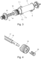
- Fig. 3
- eine beispielhafte Darstellung einer Mischkammer;
- Fig. 4
- eine beispielhafte Darstellung einer Fördervorrichtung;
- Fig. 5a und 5b
- eine beispielhafte Darstellung einer Fördervorrichtung für Baustoffe ohne Fasern;
- Fig. 6a und 6b
- eine beispielhafte Darstellung einer Fördervorrichtung für Baustoffe mit Fasern;
- Fig. 7
- eine schematische Darstellung einer beispielhaften Faser; und
- Fig. 8
- eine schematische Darstellung eines Kornes einer Gesteinskörnung des Baustoffes.
- In
Fig. 1 ist schematisch ein System zum Applizieren eines Baustoffes dargestellt. Das System 1 umfasst dabei eine Bewegungsvorrichtung 2, welche in diesem Ausführungsbeispiel als Vorrichtung mit einem kranartigen Arm ausgebildet ist. Ein Mischer 5 ist dabei an einem Kopf der Bewegungsvorrichtung 2 angeordnet. Eine erste Komponente 3 und eine zweite Komponente 4 sind jeweils dem Mischer 5 über einen ersten Schlauch 27 und einen zweiten Schlauch 28 zuführbar. Dabei hat der Mischer 5 einen ersten Einlass 7.1 und einen zweiten Einlass 7.2, an welchen die erste Komponente 3 und die zweite Komponente 4 dem Mischer 5 zugeführt werden können. Der Mischer 5 hat weiterhin einen Auslass 6, über welchen der Baustoff appliziert werden kann. - In diesem Ausführungsbeispiel wird der Mischer 5 jeweils durch die Bewegungsvorrichtung 2 an einen Ort bewegt, an welchem der Baustoff appliziert werden soll.
- In
Fig. 2 ist der Mischer 5 ausFig. 1 detaillierter dargestellt. Der Mischer 5 hat einen Antrieb 8 und eine Mischkammer 9. Die Mischkammer 9 hat dabei einen ersten Einlass 7.1, einen zweiten Einlass 7.2 und einen dritten Einlass 7.3. Zudem hat die Mischkammer 9 einen Auslass 6. Dabei kann beispielsweise der erste Einlass 7.1 für die Zuführung der ersten Komponente verwendet werden, der zweite Einlass 7.2 kann für die Zuführung von Reinigungsflüssigkeit in die Mischkammer 9 verwendet werden, und der dritte Einlass 7.3 kann für die Zuführung der zweiten Komponente des Baustoffes in die Mischkammer 9 verwendet werden. Am Auslass 6 kann beispielsweise eine Düse (nicht dargestellt) angeordnet werden, um den Baustoff in einem gewünschten Querschnitt zu applizieren. - In
Fig. 3 sind beispielhaft verschiedene Bestandteile der Mischkammer 9 dargestellt. Dabei ist ersichtlich, dass in der Mischkammer 9 eine Rührwelle 16 angeordnet ist, an welcher einerseits Rührelemente 19 und ein Förderelement 18 angeordnet ist. In diesem Ausführungsbeispiel sind die Rührelemente 19 auf einem ersten Abschnitt der Rührwelle 16 angeordnet, und die Fördervorrichtung 18 ist auf einem zweiten Abschnitt der Rührwelle 16 angeordnet. Dabei ist der erste Abschnitt der Rührwelle mit den Rührelementen 19 im Bereich der Einlässe 7.1, 7.2, 7.3 angeordnet, und die Fördervorrichtung 18 ist im Bereich des Auslasses 6 angeordnet. - In
Fig. 4 ist eine beispielhafte Fördervorrichtung 18 dargestellt. Dabei ist ersichtlich, dass die Fördervorrichtung 18 auf die Rührwelle 16 aufsteckbar ausgestaltet werden kann. In diesem Ausführungsbeispiel ist zudem ein Verriegelungselement 20 vorgesehen, um die Fördervorrichtung 18 auf der Rührwelle 16 zu sichern. - Die Rührwelle 16 hat in den gezeigten Ausführungsbeispielen Vertiefungen 17, in welchen die Rührelemente 19 angebracht werden können. Dies kann beispielsweise durch eine Verschraubung der Rührelemente auf der Rührwelle geschehen, wobei die Rührelemente ein Aussengewinde und die Vertiefungen ein Innengewinde haben. In dem gezeigten Ausführungsbeispiel sind die Rührelemente 19 als Stifte ausgebildet. Es versteht sich von selbst, dass mehr Rührelemente 19 auf der Rührwelle 16 angeordnet werden können, als dies auf den Figuren dargestellt ist.
- In den
Fig. 5a und 5b ist ein beispielhaftes Förderelement 18 dargestellt, welches sich insbesondere für Baustoffe ohne Fasern eignet. Die Fördervorrichtung 18 ist in diesem Ausführungsbeispiel als Förderschnecke ausgestaltet. Dabei hat die Förderschnecke mehrere Windungen 10.1, 10.2, 10.3, 10.4, 10.5. Zwischen den Windungen 10.1, 10.2, 10.3, 10.4, 10.5 ist jeweils ein Förderquerschnitt 11.1, 11.2, 11.3, 11.4 dargestellt. InFig. 5a ist dabei ersichtlich, dass die Förderquerschnitte 11.1, 11.2, 11.3, 11.4 kleiner werden, je näher sie an einem Auslass des Mischers (nicht dargestellt) angeordnet sind. Die Förderquerschnitte 11.1, 11.2, 11.3, 11.4 werden einerseits durch die Gestaltung der Begrenzungsfläche 12 und andererseits durch das Mass der Abstände 13.1, 13.2, 13.3, 13.4 zwischen benachbarten Windungen 10.1, 10.2, 10.3, 10.4, 10.5 bestimmt. - In dieser beispielhaften Ausführungsform ist die erste Windung 10.1, welche am weitesten entfernt ist von einem Auslass des Mischers (nicht dargestellt), mit einem kleineren Durchmesser ausgebildet als die nachfolgenden Windungen 10.2, 10.3, 10.4, 10.5. Zudem hat die erste Windung 10.1 eine Aussenfläche, welche durch einen Winkel α abgeschrägt ausgestaltet ist. Dabei ist eine erste Kante 22 niedriger ausgebildet als eine zweite Kante 23, wobei die erste Kante 22 weiter vom Auslass des Mischers (nicht dargestellt) beabstandet ist als die zweite Kante 23.
- In
Fig. 5b ist dieselbe Fördervorrichtung wie inFig. 5a abgebildet, jedoch in einer perspektivischen Darstellung und als Schnittzeichnung. InFig. 5b ist zudem ersichtlich, dass die Fördervorrichtung 18 auf der Rührwelle 16 aufgesteckt und gesichert werden kann (vgl. dazuFig. 4 ). - In den
Fig. 6a und 6b ist eine weitere beispielhafte Fördervorrichtung 18 dargestellt, welche sich insbesondere für Baustoffe mit Fasern eignet. In diesem Ausführungsbeispiel ist die erste Windung 10.1 wiederum abgeschrägt und kleiner als die weiteren Windungen 10.2, 10.3. Im Unterschied zur Fördervorrichtung in denFig. 5a und 5b sind die Abstände 13.1, 13.2 zwischen den Windungen 10.1, 10.2, 10.3 in diesem Ausführungsbeispiel gleich gross. Insbesondere sind die Abstände 13.1, 13.2 so gewählt, dass sie zumindest 80% einer Länge der Fasern des Baustoffes betragen. - Die Förderquerschnitte 11.1, 11.2 verkleinern sich in diesem Ausführungsbeispiel ebenfalls von Windung zu Windung, jedoch weniger stark als im Ausführungsbeispiel gemäss den
Fig. 5a und 5b . In diesem Ausführungsbeispiel hat zudem die Begrenzungsfläche 12 der Fördervorrichtung 18 im Wesentlichen einen geradlinigen Querschnitt. - In
Fig. 6b ist dieselbe Fördervorrichtung 18 wie inFig. 6a dargestellt, jedoch in perspektivischer Darstellung und als Schnitt. Wiederum ist dabei ersichtlich, wie die Fördervorrichtung 18 auf der Rührwelle aufgesteckt und gesichert werden kann (vgl. dazuFig. 4 ). - In
Fig. 7 ist eine beispielhafte Faser 25 dargestellt. Die Faser 25 hat dabei eine Länge 25.1, eine Breite 25.2 und eine Höhe 25.3. Die Höhe 25.3 der Faser 25 ist insbesondere so gewählt, dass in Abstimmung mit dem Fasermaterial die Faser 25 flexibel ausgebildet ist. - In
Fig. 8 ist ein beispielhaftes Korn 26 der Gesteinskörnung des Baustoffes dargestellt. Das Korn 26 kann, wie hier dargestellt, eine unregelmässig gestaltete Oberfläche aufweisen. Ein Durchmesser 26.1 entspricht einem grössten Durchmesser des Kornes 26. -
- 1
- System
- 2
- Bewegungsvorrichtung
- 3
- erste Komponente
- 4
- zweite Komponente
- 5
- Mischer
- 6
- Auslass
- 7
- Einlass
- 7.1
- erster Einlass
- 7.2
- zweiter Einlass
- 7.3
- dritter Einlass
- 8
- Antrieb
- 9
- Mischkammer
- 10
- Windung
- 10.1
- erste Windung
- 10.2
- zweite Windung
- 10.3
- dritte Windung
- 10.4
- vierte Windung
- 10.5
- fünfte Windung
- 11
- Förderquerschnitt
- 11.1
- erster Förderquerschnitt
- 11.2
- zweiter Förderquerschnitt
- 11.3
- dritter Förderquerschnitt
- 11.4
- vierter Förderquerschnitt
- 12
- Begrenzungsfläche
- 13
- Abstand zwischen benachbarten Windungen
- 13.1
- erster Abstand
- 13.2
- zweiter Abstand
- 13.3
- dritter Abstand
- 13.4
- vierter Abstand
- 16
- Rührwelle
- 17
- Vertiefung
- 18
- Förderelement
- 19
- Rührelement
- 20
- Verriegelungselement
- 22
- erste Kante
- 23
- zweite Kante
- 25
- Faser
- 26
- Korn
- 27
- erster Schlauch
- 28
- zweiter Schlauch
Claims (12)
- System (1) zum Applizieren eines Baustoffes, das System (1) umfassend:Eine Bewegungsvorrichtung (2) zur Veränderung eines Applikationsortes in einem Raum;Eine erste Komponente (3) des Baustoffes;Eine zweite Komponente (4) des Baustoffes; undEinen Mischer (5) zur Vermischung der ersten Komponente (3) und der zweiten Komponente (4), wobei der Mischer (5) einen Antrieb (8) und eine Mischkammer (9) mit einer Rührwelle (16) und einer Fördervorrichtung (18) umfasst, wobei die Fördervorrichtung (18) als Förderschnecke mit Windungen (10, 10.1, 10.2, 10.3, 10.4, 10.5) ausgebildet ist;- Wobei der Baustoff Fasern (25) enthält und:o ein Abstand (13.1, 13.2) zwischen benachbarten Windungen (10.1, 10.2, 10.3) der Förderschnecke zumindest 40% einer Länge der Fasern (25) beträgt, und/odero ein Abstand zwischen benachbarten Rührelementen (19) der Rührwelle (16) zumindest 40% einer Läge der Fasern (25) beträgt; oder- Wobei der Baustoff keine Fasern (25) enthält und:o Abstände (13.1, 13.2, 13.3, 13.4) zwischen benachbarten Windungen (10.1, 10.2, 10.3, 10.4, 10.5) der Förderschnecke kleiner sind, je näher die Windungen (10.1, 10.2, 10.3, 10.4, 10.5) bei einem Auslass (6) angeordnet sind, und/odero ein Abstand zwischen benachbarten Rührelementen (19) der Rührwelle (16) von 5 bis 50 mm beträgt; oder- Wobei die erste Komponente eine Gesteinskörnung enthält, und wobei ein Abstand zwischen Enden von Rührelementen (19) der Rührwelle (16) und einer Innenwand der Mischkammer (9) zumindest gleich gross ist wie ein Durchmesser der Körner (26) der Gesteinskörnung;dadurch gekennzeichnet, dass die erste Komponente (3) des Baustoffes einen pumpbaren Beton umfasst, und wobei die zweite Komponente (4) des Baustoffes ein Betonzusatzmittel, welches einen Erstarrungsbeschleuniger enthält, umfasst.
- System (1) nach Anspruch 1, wobei eine erste Windung (10.1) der Fördervorrichtung (18) einen kleineren Durchmesser hat als nachfolgende Windungen (10.2, 10.3, 10.4, 10.5).
- System (1) nach Anspruch 2, wobei die erste Windung (10.1) der Fördervorrichtung (18) eine Aussenfläche hat, welche durch einen Winkel (α) abgeschrägt ist, so dass eine erste Kante (22) niedriger ist als eine zweite Kante (23), wobei die erste Kante (22) weiter entfernt ist von einem Auslass (6) des Mischers als die zweite Kante (23).
- System (1) nach einem der vorhergehenden Ansprüche, wobei die Rührelemente (19) Aussengewinde aufweisen und wobei die Rührwelle (16) Vertiefungen (17) mit Innengewinden aufweist, so dass die Rührelemente (19) durch Drehung von der Rührwelle (16) einsetzbar und entnehmbar sind.
- System (1) nach Anspruch 4, wobei die Rührelemente (19) der Rührwelle (16) als Stifte ausgebildet sind.
- System (1) nach einem der vorhergehenden Ansprüche, wobei der Baustoff Fasern (25) enthält und wobei Abstände (13.1, 13.2) zwischen benachbarten Windungen (10.1, 10.2, 10.3) im Wesentlichen gleich gross sind.
- System (1) nach einem der vorhergehenden Ansprüche, wobei der Baustoff Fasern (25) enthält und wobei die Fördervorrichtung (18) zwei bis vier Windungen (10.1, 10.2, 10.3, 10.4, 10.5) hat.
- System (1) nach einem der vorhergehenden Ansprüche, wobei der Baustoff Fasern (25) enthält und wobei ein Querschnitt einer Begrenzungsfläche (12) der Fördervorrichtung (18) im Wesentlichen geradlinig oder im Wesentlichen S-förmig ausgebildet ist.
- System (1) nach einem der vorhergehenden Ansprüche, wobei der Baustoff Fasern (25) enthält und wobei die Fasern (25) eine Länge von 5 bis 20 mm haben, und/oder eine Breite von 5 bis 2000 µm haben, und/oder eine Höhe von 5 bis 100 µm haben.
- System (1) nach einem der vorhergehenden Ansprüche, wobei der Baustoff Fasern (25) enthält, wobei die Fasern (25) zumindest teilweise aus Metall oder aus Kunststoff oder aus Glas oder aus Karbon bestehen, und/oder
wobei die Fasern (25) flexibel sind. - System (1) nach einem der vorhergehenden Ansprüche, wobei der Baustoff Fasern (25) enthält, wobei 1 l Baustoff zwischen 1'000 und 1'000'000'000 Fasern (25) hat.
- System (1) nach einem der Ansprüche 1 bis 5, wobei der Baustoff keine Fasern (25) enthält, und wobei die Fördervorrichtung (18) zwei bis zehn Windungen (10.1, 10.2, 10.3, 10.4, 10.5) hat.
Applications Claiming Priority (2)
| Application Number | Priority Date | Filing Date | Title |
|---|---|---|---|
| EP17185652 | 2017-08-09 | ||
| PCT/EP2018/071638 WO2019030329A1 (de) | 2017-08-09 | 2018-08-09 | System zum applizieren eines baustoffes |
Publications (2)
| Publication Number | Publication Date |
|---|---|
| EP3600808A1 EP3600808A1 (de) | 2020-02-05 |
| EP3600808B1 true EP3600808B1 (de) | 2023-05-10 |
Family
ID=59631584
Family Applications (1)
| Application Number | Title | Priority Date | Filing Date |
|---|---|---|---|
| EP18749396.0A Active EP3600808B1 (de) | 2017-08-09 | 2018-08-09 | System zum applizieren eines baustoffes |
Country Status (5)
| Country | Link |
|---|---|
| US (1) | US11731310B2 (de) |
| EP (1) | EP3600808B1 (de) |
| CN (1) | CN110997257B (de) |
| DK (1) | DK3600808T3 (de) |
| WO (1) | WO2019030329A1 (de) |
Families Citing this family (3)
| Publication number | Priority date | Publication date | Assignee | Title |
|---|---|---|---|---|
| DK3600808T3 (da) * | 2017-08-09 | 2023-07-31 | Sika Tech Ag | System til applicering af et byggemateriale |
| DE102020134316A1 (de) | 2020-12-18 | 2022-06-23 | Kulzer Gmbh | Rotorwelle mit Schneckengewinde für einen dynamischen Mischer zum Mischen niedrig- bis hochviskoser Komponenten |
| CN115253834B (zh) * | 2022-08-01 | 2024-02-09 | 大连理工大学 | 一种高通量被动式旋流强化微混合器 |
Family Cites Families (35)
| Publication number | Priority date | Publication date | Assignee | Title |
|---|---|---|---|---|
| US1732281A (en) * | 1929-10-22 | Method oe making plastic compounds | ||
| US1753716A (en) * | 1928-04-25 | 1930-04-08 | Jack M Owen | Mixer for cement |
| US3006615A (en) * | 1957-07-05 | 1961-10-31 | Hoge Warren Zimmermann Co | Continuous mixing, metering and delivering apparatus |
| US3346240A (en) * | 1965-01-15 | 1967-10-10 | Ready T Pour Inc | Mixing apparatus |
| US3430929A (en) * | 1967-11-16 | 1969-03-04 | Southington Mfg Inc | Continuous operation mulling apparatus and method for accurately proportioning foundry sand ingredients |
| US3606277A (en) * | 1969-09-22 | 1971-09-20 | Brahim Ijac Kader | Transit-mix concrete truck |
| DE2261598A1 (de) * | 1972-12-15 | 1974-06-20 | Schnitzler Erwin Dr Dipl Ing | Beleimmaschine |
| IT1079502B (it) * | 1975-05-27 | 1985-05-13 | Mathis Fertigputz | Dispositivo per la fabbricazione continua di matla impasata |
| US4039169A (en) * | 1976-02-02 | 1977-08-02 | Carver Foundry Products | Continuous sand muller |
| US4175867A (en) * | 1978-03-01 | 1979-11-27 | Maso-Therm Corp. | Process and apparatus for static mixing |
| US4322168A (en) * | 1980-04-25 | 1982-03-30 | Carver Foundry Products | Two-tube continuous sand muller |
| US4492478A (en) * | 1981-09-18 | 1985-01-08 | Yasuro Ito | Method and apparatus for applying mortar or concrete |
| US4499561A (en) * | 1982-12-06 | 1985-02-12 | Hoge, Warren, Zimmerman Company | Apparatus for continuously producing a dry material and liquid slurry |
| DE3532722A1 (de) * | 1985-09-13 | 1987-03-26 | Heidelberger Zement Ag | Vorrichtung und verfahren zur kontinuierlichen bereitstellung von hydraulisch abbindender masse |
| US4844340A (en) * | 1986-07-30 | 1989-07-04 | Railway Technical Research Institute | Method and apparatus for spraying an inorganic hydraulic material composition containing reinforcing short fibers |
| JP3080627B2 (ja) * | 1989-12-13 | 2000-08-28 | 三菱レイヨン株式会社 | 連続混練機 |
| US5352035A (en) * | 1993-03-23 | 1994-10-04 | Hydromix, Inc. | Concrete mixing system with cement/water premixer |
| US5529471A (en) | 1995-02-03 | 1996-06-25 | University Of Southern California | Additive fabrication apparatus and method |
| NL1011156C2 (nl) * | 1999-01-27 | 2000-07-31 | Rooijen Silo En Mengtechnieken | Silo voor aanmaak van specie. |
| US6454972B1 (en) * | 1999-11-24 | 2002-09-24 | Sandia Corporation | Solid freeform fabrication using chemically reactive suspensions |
| AU2002950211A0 (en) * | 2002-07-16 | 2002-09-12 | Unitex Granular Marble Pty Ltd | Measuring and dispensing apparatus |
| US7793691B2 (en) * | 2005-11-02 | 2010-09-14 | Thermadrum, Llc | Thermal insulating device for concrete mixing trucks |
| DE102007004768A1 (de) * | 2007-01-31 | 2008-08-07 | Knauf Marmorit Gmbh | Durchlaufmischer zum Anmachen von Mörtel, insbesondere Werktrockenmörtel, mit Wasser und Verfahren zum Bearbeiten von Wärme zu dämmenden Fertigwandelementen für Gebäude mit Hilfe eines derartigen Durchlaufmischers |
| CN201780061U (zh) | 2010-07-23 | 2011-03-30 | 浏阳市达浒花炮艺术焰火燃放集团有限公司 | 一种烟火药制药柱设备 |
| GB201118807D0 (en) | 2011-11-01 | 2011-12-14 | Univ Loughborough | Method and apparatus |
| US20140269146A1 (en) * | 2013-03-15 | 2014-09-18 | Oshkosh Corporation | Concrete mixing drum drive system |
| CN205086160U (zh) * | 2015-11-05 | 2016-03-16 | 都书鹏 | 一种用于3d建筑打印机的注射式连续注浆机 |
| CN108698001B (zh) * | 2016-03-01 | 2022-08-02 | Sika技术股份公司 | 混合器、用于施加建造材料的系统和用于由建筑材料制造结构的方法 |
| CN205517447U (zh) | 2016-04-08 | 2016-08-31 | 四川科新机电股份有限公司 | 主轴长度可调、桨叶可拆的搅拌机构 |
| CN106891439A (zh) * | 2017-04-21 | 2017-06-27 | 合肥智慧龙机械设计有限公司 | 一种间断下料的建筑用水泥搅拌装置 |
| CN110997261A (zh) * | 2017-08-09 | 2020-04-10 | Sika技术股份公司 | 用于涂布含纤维的矿物粘合剂成分的方法 |
| DK3600808T3 (da) * | 2017-08-09 | 2023-07-31 | Sika Tech Ag | System til applicering af et byggemateriale |
| US11534939B2 (en) * | 2017-08-09 | 2022-12-27 | Sika Technology Ag | Device for applying a building material |
| JP7216703B2 (ja) * | 2017-08-09 | 2023-02-01 | シーカ テクノロジー アクチェンゲゼルシャフト | 建築材料を適用するためのシステム |
| WO2019030255A1 (de) * | 2017-08-09 | 2019-02-14 | Sika Technology Ag | Verfahren für den 3d-druck von mineralischen bindemittelzusammensetzungen |
-
2018
- 2018-08-09 DK DK18749396.0T patent/DK3600808T3/da active
- 2018-08-09 US US16/634,395 patent/US11731310B2/en active Active
- 2018-08-09 EP EP18749396.0A patent/EP3600808B1/de active Active
- 2018-08-09 WO PCT/EP2018/071638 patent/WO2019030329A1/de not_active Ceased
- 2018-08-09 CN CN201880051344.1A patent/CN110997257B/zh not_active Expired - Fee Related
Also Published As
| Publication number | Publication date |
|---|---|
| WO2019030329A1 (de) | 2019-02-14 |
| CN110997257A (zh) | 2020-04-10 |
| DK3600808T3 (da) | 2023-07-31 |
| EP3600808A1 (de) | 2020-02-05 |
| CN110997257B (zh) | 2022-10-28 |
| US11731310B2 (en) | 2023-08-22 |
| US20210114252A1 (en) | 2021-04-22 |
Similar Documents
| Publication | Publication Date | Title |
|---|---|---|
| EP3646943B1 (de) | Verfahren zum herstellen einer struktur aus baumaterial | |
| EP4086056B1 (de) | Verfahren zum herstellen einer struktur aus einem baustoff | |
| DE10204921C1 (de) | Dispergier-Vorrichtung | |
| EP3600809B2 (de) | System zum applizieren eines baustoffes | |
| DE2637558A1 (de) | Verfahren und vorrichtung zur erzeugung eines kontinuierlichen materialstroms | |
| DE69936224T2 (de) | Einfache extruderschnecke zum effizienten mischen unmischbarer polymermaterialien | |
| DE102018118883B3 (de) | Verfahren und Vorrichtung zur Herstellung eines faserverstärkten Plastifikats und Verwendung der Vorrichtung zur additiven Fertigung | |
| DE3210978A1 (de) | Mischvorrichtung fuer mehrkomponentenkunststoffe, insbesondere polyurethan | |
| DE60204101T2 (de) | Knetvorrichtung und Verfahren zum Kneten von Kautschuk oder Kautschukzusammensetzungen | |
| EP3600808A1 (de) | System zum applizieren eines baustoffes | |
| DE2334796A1 (de) | Glasfaserverstaerktes rohr aus betonartigem material | |
| DE69311759T2 (de) | Pneumatisches Transportverfahren für Schüttgüter wie Mörtel, Beton oder Sand und Einrichtung zum Transportieren und Mischen zur Durchführung des Verfahrens | |
| EP3141362B1 (de) | Verfahren zur herstellung einer struktur aus mörtel oder beton und dazu geeignete anordnung | |
| CH686367A5 (de) | Kunststoffasern zur Beimischung in aushaertende Massen, insbesondere Beton oder Moertel. | |
| DE202024101132U1 (de) | 3D-Druckkopf | |
| DE102011079435A1 (de) | Kunststoffspritzguss-Werkstück und Verfahren zum Herstellen eines Kunststoffspritzguss-Werkstücks | |
| EP2868392A1 (de) | Hülse, Austragseinrichtung umfassend die Hülse und Verfahren | |
| DE102007034067B9 (de) | Transportbetonwerk mit Polyurethan-Betonschlauch | |
| EP1623807B2 (de) | Verfahren und Vorrichtung zur Herstellung eines Holzwerkstoffkörpers | |
| DE69909706T2 (de) | Drosselmittel für extruder am transfermischertyp | |
| DE19812154A1 (de) | Vorrichtung zum Mischen und Fördern von Stoffgemischen | |
| DE60210150T2 (de) | Misch- und spritzeinheit für polyurethan mit zwei oder mehr flüssigkomponenten, und spritz- und reinigungsverfahren | |
| WO2018192698A1 (de) | Einschnecken-plastifiziereinheit | |
| EP0085876B1 (de) | Vorrichtung zum Erzeugen eines chemisch reaktionsfähigen Gemisches | |
| DE102024106634A1 (de) | 3D-Druckkopf |
Legal Events
| Date | Code | Title | Description |
|---|---|---|---|
| STAA | Information on the status of an ep patent application or granted ep patent |
Free format text: STATUS: UNKNOWN |
|
| STAA | Information on the status of an ep patent application or granted ep patent |
Free format text: STATUS: THE INTERNATIONAL PUBLICATION HAS BEEN MADE |
|
| PUAI | Public reference made under article 153(3) epc to a published international application that has entered the european phase |
Free format text: ORIGINAL CODE: 0009012 |
|
| STAA | Information on the status of an ep patent application or granted ep patent |
Free format text: STATUS: REQUEST FOR EXAMINATION WAS MADE |
|
| 17P | Request for examination filed |
Effective date: 20191024 |
|
| AK | Designated contracting states |
Kind code of ref document: A1 Designated state(s): AL AT BE BG CH CY CZ DE DK EE ES FI FR GB GR HR HU IE IS IT LI LT LU LV MC MK MT NL NO PL PT RO RS SE SI SK SM TR |
|
| AX | Request for extension of the european patent |
Extension state: BA ME |
|
| DAV | Request for validation of the european patent (deleted) | ||
| DAX | Request for extension of the european patent (deleted) | ||
| STAA | Information on the status of an ep patent application or granted ep patent |
Free format text: STATUS: EXAMINATION IS IN PROGRESS |
|
| 17Q | First examination report despatched |
Effective date: 20211125 |
|
| RIC1 | Information provided on ipc code assigned before grant |
Ipc: B01F 33/501 20220101ALI20221220BHEP Ipc: B01F 27/2123 20220101ALI20221220BHEP Ipc: B01F 27/192 20220101ALI20221220BHEP Ipc: B01F 27/1121 20220101ALI20221220BHEP Ipc: B01F 27/07 20220101ALI20221220BHEP Ipc: B33Y 30/00 20150101ALI20221220BHEP Ipc: B33Y 10/00 20150101ALI20221220BHEP Ipc: B28C 5/40 20060101ALI20221220BHEP Ipc: B28C 5/12 20060101ALI20221220BHEP Ipc: B28B 1/00 20060101AFI20221220BHEP |
|
| GRAP | Despatch of communication of intention to grant a patent |
Free format text: ORIGINAL CODE: EPIDOSNIGR1 |
|
| STAA | Information on the status of an ep patent application or granted ep patent |
Free format text: STATUS: GRANT OF PATENT IS INTENDED |
|
| INTG | Intention to grant announced |
Effective date: 20230222 |
|
| GRAS | Grant fee paid |
Free format text: ORIGINAL CODE: EPIDOSNIGR3 |
|
| GRAA | (expected) grant |
Free format text: ORIGINAL CODE: 0009210 |
|
| STAA | Information on the status of an ep patent application or granted ep patent |
Free format text: STATUS: THE PATENT HAS BEEN GRANTED |
|
| AK | Designated contracting states |
Kind code of ref document: B1 Designated state(s): AL AT BE BG CH CY CZ DE DK EE ES FI FR GB GR HR HU IE IS IT LI LT LU LV MC MK MT NL NO PL PT RO RS SE SI SK SM TR |
|
| REG | Reference to a national code |
Ref country code: GB Ref legal event code: FG4D Free format text: NOT ENGLISH |
|
| REG | Reference to a national code |
Ref country code: AT Ref legal event code: REF Ref document number: 1566262 Country of ref document: AT Kind code of ref document: T Effective date: 20230515 Ref country code: CH Ref legal event code: EP |
|
| REG | Reference to a national code |
Ref country code: DE Ref legal event code: R096 Ref document number: 502018012132 Country of ref document: DE |
|
| REG | Reference to a national code |
Ref country code: IE Ref legal event code: FG4D Free format text: LANGUAGE OF EP DOCUMENT: GERMAN |
|
| REG | Reference to a national code |
Ref country code: DK Ref legal event code: T3 Effective date: 20230727 |
|
| REG | Reference to a national code |
Ref country code: NL Ref legal event code: FP |
|
| REG | Reference to a national code |
Ref country code: LT Ref legal event code: MG9D |
|
| PG25 | Lapsed in a contracting state [announced via postgrant information from national office to epo] |
Ref country code: SE Free format text: LAPSE BECAUSE OF FAILURE TO SUBMIT A TRANSLATION OF THE DESCRIPTION OR TO PAY THE FEE WITHIN THE PRESCRIBED TIME-LIMIT Effective date: 20230510 Ref country code: PT Free format text: LAPSE BECAUSE OF FAILURE TO SUBMIT A TRANSLATION OF THE DESCRIPTION OR TO PAY THE FEE WITHIN THE PRESCRIBED TIME-LIMIT Effective date: 20230911 Ref country code: NO Free format text: LAPSE BECAUSE OF FAILURE TO SUBMIT A TRANSLATION OF THE DESCRIPTION OR TO PAY THE FEE WITHIN THE PRESCRIBED TIME-LIMIT Effective date: 20230810 Ref country code: ES Free format text: LAPSE BECAUSE OF FAILURE TO SUBMIT A TRANSLATION OF THE DESCRIPTION OR TO PAY THE FEE WITHIN THE PRESCRIBED TIME-LIMIT Effective date: 20230510 |
|
| PGFP | Annual fee paid to national office [announced via postgrant information from national office to epo] |
Ref country code: CZ Payment date: 20230725 Year of fee payment: 6 |
|
| PG25 | Lapsed in a contracting state [announced via postgrant information from national office to epo] |
Ref country code: RS Free format text: LAPSE BECAUSE OF FAILURE TO SUBMIT A TRANSLATION OF THE DESCRIPTION OR TO PAY THE FEE WITHIN THE PRESCRIBED TIME-LIMIT Effective date: 20230510 Ref country code: PL Free format text: LAPSE BECAUSE OF FAILURE TO SUBMIT A TRANSLATION OF THE DESCRIPTION OR TO PAY THE FEE WITHIN THE PRESCRIBED TIME-LIMIT Effective date: 20230510 Ref country code: LV Free format text: LAPSE BECAUSE OF FAILURE TO SUBMIT A TRANSLATION OF THE DESCRIPTION OR TO PAY THE FEE WITHIN THE PRESCRIBED TIME-LIMIT Effective date: 20230510 Ref country code: LT Free format text: LAPSE BECAUSE OF FAILURE TO SUBMIT A TRANSLATION OF THE DESCRIPTION OR TO PAY THE FEE WITHIN THE PRESCRIBED TIME-LIMIT Effective date: 20230510 Ref country code: IS Free format text: LAPSE BECAUSE OF FAILURE TO SUBMIT A TRANSLATION OF THE DESCRIPTION OR TO PAY THE FEE WITHIN THE PRESCRIBED TIME-LIMIT Effective date: 20230910 Ref country code: HR Free format text: LAPSE BECAUSE OF FAILURE TO SUBMIT A TRANSLATION OF THE DESCRIPTION OR TO PAY THE FEE WITHIN THE PRESCRIBED TIME-LIMIT Effective date: 20230510 Ref country code: GR Free format text: LAPSE BECAUSE OF FAILURE TO SUBMIT A TRANSLATION OF THE DESCRIPTION OR TO PAY THE FEE WITHIN THE PRESCRIBED TIME-LIMIT Effective date: 20230811 |
|
| PGFP | Annual fee paid to national office [announced via postgrant information from national office to epo] |
Ref country code: DK Payment date: 20230731 Year of fee payment: 6 |
|
| PG25 | Lapsed in a contracting state [announced via postgrant information from national office to epo] |
Ref country code: FI Free format text: LAPSE BECAUSE OF FAILURE TO SUBMIT A TRANSLATION OF THE DESCRIPTION OR TO PAY THE FEE WITHIN THE PRESCRIBED TIME-LIMIT Effective date: 20230510 |
|
| PG25 | Lapsed in a contracting state [announced via postgrant information from national office to epo] |
Ref country code: SK Free format text: LAPSE BECAUSE OF FAILURE TO SUBMIT A TRANSLATION OF THE DESCRIPTION OR TO PAY THE FEE WITHIN THE PRESCRIBED TIME-LIMIT Effective date: 20230510 |
|
| PG25 | Lapsed in a contracting state [announced via postgrant information from national office to epo] |
Ref country code: SM Free format text: LAPSE BECAUSE OF FAILURE TO SUBMIT A TRANSLATION OF THE DESCRIPTION OR TO PAY THE FEE WITHIN THE PRESCRIBED TIME-LIMIT Effective date: 20230510 Ref country code: SK Free format text: LAPSE BECAUSE OF FAILURE TO SUBMIT A TRANSLATION OF THE DESCRIPTION OR TO PAY THE FEE WITHIN THE PRESCRIBED TIME-LIMIT Effective date: 20230510 Ref country code: RO Free format text: LAPSE BECAUSE OF FAILURE TO SUBMIT A TRANSLATION OF THE DESCRIPTION OR TO PAY THE FEE WITHIN THE PRESCRIBED TIME-LIMIT Effective date: 20230510 Ref country code: EE Free format text: LAPSE BECAUSE OF FAILURE TO SUBMIT A TRANSLATION OF THE DESCRIPTION OR TO PAY THE FEE WITHIN THE PRESCRIBED TIME-LIMIT Effective date: 20230510 |
|
| REG | Reference to a national code |
Ref country code: DE Ref legal event code: R097 Ref document number: 502018012132 Country of ref document: DE |
|
| PG25 | Lapsed in a contracting state [announced via postgrant information from national office to epo] |
Ref country code: MC Free format text: LAPSE BECAUSE OF FAILURE TO SUBMIT A TRANSLATION OF THE DESCRIPTION OR TO PAY THE FEE WITHIN THE PRESCRIBED TIME-LIMIT Effective date: 20230510 |
|
| PLBE | No opposition filed within time limit |
Free format text: ORIGINAL CODE: 0009261 |
|
| STAA | Information on the status of an ep patent application or granted ep patent |
Free format text: STATUS: NO OPPOSITION FILED WITHIN TIME LIMIT |
|
| PG25 | Lapsed in a contracting state [announced via postgrant information from national office to epo] |
Ref country code: MC Free format text: LAPSE BECAUSE OF FAILURE TO SUBMIT A TRANSLATION OF THE DESCRIPTION OR TO PAY THE FEE WITHIN THE PRESCRIBED TIME-LIMIT Effective date: 20230510 |
|
| PG25 | Lapsed in a contracting state [announced via postgrant information from national office to epo] |
Ref country code: LU Free format text: LAPSE BECAUSE OF NON-PAYMENT OF DUE FEES Effective date: 20230809 |
|
| 26N | No opposition filed |
Effective date: 20240213 |
|
| GBPC | Gb: european patent ceased through non-payment of renewal fee |
Effective date: 20230810 |
|
| PG25 | Lapsed in a contracting state [announced via postgrant information from national office to epo] |
Ref country code: LU Free format text: LAPSE BECAUSE OF NON-PAYMENT OF DUE FEES Effective date: 20230809 |
|
| PG25 | Lapsed in a contracting state [announced via postgrant information from national office to epo] |
Ref country code: SI Free format text: LAPSE BECAUSE OF FAILURE TO SUBMIT A TRANSLATION OF THE DESCRIPTION OR TO PAY THE FEE WITHIN THE PRESCRIBED TIME-LIMIT Effective date: 20230510 |
|
| REG | Reference to a national code |
Ref country code: BE Ref legal event code: MM Effective date: 20230831 |
|
| REG | Reference to a national code |
Ref country code: IE Ref legal event code: MM4A |
|
| PG25 | Lapsed in a contracting state [announced via postgrant information from national office to epo] |
Ref country code: SI Free format text: LAPSE BECAUSE OF FAILURE TO SUBMIT A TRANSLATION OF THE DESCRIPTION OR TO PAY THE FEE WITHIN THE PRESCRIBED TIME-LIMIT Effective date: 20230510 Ref country code: IT Free format text: LAPSE BECAUSE OF FAILURE TO SUBMIT A TRANSLATION OF THE DESCRIPTION OR TO PAY THE FEE WITHIN THE PRESCRIBED TIME-LIMIT Effective date: 20230510 |
|
| PG25 | Lapsed in a contracting state [announced via postgrant information from national office to epo] |
Ref country code: IE Free format text: LAPSE BECAUSE OF NON-PAYMENT OF DUE FEES Effective date: 20230809 |
|
| PG25 | Lapsed in a contracting state [announced via postgrant information from national office to epo] |
Ref country code: GB Free format text: LAPSE BECAUSE OF NON-PAYMENT OF DUE FEES Effective date: 20230810 |
|
| PG25 | Lapsed in a contracting state [announced via postgrant information from national office to epo] |
Ref country code: IE Free format text: LAPSE BECAUSE OF NON-PAYMENT OF DUE FEES Effective date: 20230809 Ref country code: GB Free format text: LAPSE BECAUSE OF NON-PAYMENT OF DUE FEES Effective date: 20230810 |
|
| PG25 | Lapsed in a contracting state [announced via postgrant information from national office to epo] |
Ref country code: BE Free format text: LAPSE BECAUSE OF NON-PAYMENT OF DUE FEES Effective date: 20230831 |
|
| REG | Reference to a national code |
Ref country code: AT Ref legal event code: MM01 Ref document number: 1566262 Country of ref document: AT Kind code of ref document: T Effective date: 20230809 |
|
| PG25 | Lapsed in a contracting state [announced via postgrant information from national office to epo] |
Ref country code: AT Free format text: LAPSE BECAUSE OF NON-PAYMENT OF DUE FEES Effective date: 20230809 |
|
| PG25 | Lapsed in a contracting state [announced via postgrant information from national office to epo] |
Ref country code: AT Free format text: LAPSE BECAUSE OF NON-PAYMENT OF DUE FEES Effective date: 20230809 |
|
| PG25 | Lapsed in a contracting state [announced via postgrant information from national office to epo] |
Ref country code: BG Free format text: LAPSE BECAUSE OF FAILURE TO SUBMIT A TRANSLATION OF THE DESCRIPTION OR TO PAY THE FEE WITHIN THE PRESCRIBED TIME-LIMIT Effective date: 20230510 |
|
| PG25 | Lapsed in a contracting state [announced via postgrant information from national office to epo] |
Ref country code: BG Free format text: LAPSE BECAUSE OF FAILURE TO SUBMIT A TRANSLATION OF THE DESCRIPTION OR TO PAY THE FEE WITHIN THE PRESCRIBED TIME-LIMIT Effective date: 20230510 |
|
| REG | Reference to a national code |
Ref country code: DK Ref legal event code: EBP Effective date: 20240831 |
|
| PG25 | Lapsed in a contracting state [announced via postgrant information from national office to epo] |
Ref country code: CZ Free format text: LAPSE BECAUSE OF NON-PAYMENT OF DUE FEES Effective date: 20240809 |
|
| PG25 | Lapsed in a contracting state [announced via postgrant information from national office to epo] |
Ref country code: DK Free format text: LAPSE BECAUSE OF NON-PAYMENT OF DUE FEES Effective date: 20240831 |
|
| PG25 | Lapsed in a contracting state [announced via postgrant information from national office to epo] |
Ref country code: CY Free format text: LAPSE BECAUSE OF FAILURE TO SUBMIT A TRANSLATION OF THE DESCRIPTION OR TO PAY THE FEE WITHIN THE PRESCRIBED TIME-LIMIT; INVALID AB INITIO Effective date: 20180809 |
|
| PG25 | Lapsed in a contracting state [announced via postgrant information from national office to epo] |
Ref country code: HU Free format text: LAPSE BECAUSE OF FAILURE TO SUBMIT A TRANSLATION OF THE DESCRIPTION OR TO PAY THE FEE WITHIN THE PRESCRIBED TIME-LIMIT; INVALID AB INITIO Effective date: 20180809 |
|
| PGFP | Annual fee paid to national office [announced via postgrant information from national office to epo] |
Ref country code: NL Payment date: 20250723 Year of fee payment: 8 |
|
| PGFP | Annual fee paid to national office [announced via postgrant information from national office to epo] |
Ref country code: DE Payment date: 20250724 Year of fee payment: 8 |
|
| PGFP | Annual fee paid to national office [announced via postgrant information from national office to epo] |
Ref country code: FR Payment date: 20250725 Year of fee payment: 8 |
|
| PGFP | Annual fee paid to national office [announced via postgrant information from national office to epo] |
Ref country code: CH Payment date: 20250902 Year of fee payment: 8 |
|
| PG25 | Lapsed in a contracting state [announced via postgrant information from national office to epo] |
Ref country code: TR Free format text: LAPSE BECAUSE OF FAILURE TO SUBMIT A TRANSLATION OF THE DESCRIPTION OR TO PAY THE FEE WITHIN THE PRESCRIBED TIME-LIMIT Effective date: 20230510 |