EP3600903B1 - Élément de sécurité - Google Patents
Élément de sécurité Download PDFInfo
- Publication number
- EP3600903B1 EP3600903B1 EP18712904.4A EP18712904A EP3600903B1 EP 3600903 B1 EP3600903 B1 EP 3600903B1 EP 18712904 A EP18712904 A EP 18712904A EP 3600903 B1 EP3600903 B1 EP 3600903B1
- Authority
- EP
- European Patent Office
- Prior art keywords
- tracks
- case
- security element
- microstructures
- microstructure
- Prior art date
- Legal status (The legal status is an assumption and is not a legal conclusion. Google has not performed a legal analysis and makes no representation as to the accuracy of the status listed.)
- Active
Links
Images











Classifications
-
- B—PERFORMING OPERATIONS; TRANSPORTING
- B42—BOOKBINDING; ALBUMS; FILES; SPECIAL PRINTED MATTER
- B42D—BOOKS; BOOK COVERS; LOOSE LEAVES; PRINTED MATTER CHARACTERISED BY IDENTIFICATION OR SECURITY FEATURES; PRINTED MATTER OF SPECIAL FORMAT OR STYLE NOT OTHERWISE PROVIDED FOR; DEVICES FOR USE THEREWITH AND NOT OTHERWISE PROVIDED FOR; MOVABLE-STRIP WRITING OR READING APPARATUS
- B42D25/00—Information-bearing cards or sheet-like structures characterised by identification or security features; Manufacture thereof
- B42D25/30—Identification or security features, e.g. for preventing forgery
- B42D25/324—Reliefs
-
- B—PERFORMING OPERATIONS; TRANSPORTING
- B42—BOOKBINDING; ALBUMS; FILES; SPECIAL PRINTED MATTER
- B42D—BOOKS; BOOK COVERS; LOOSE LEAVES; PRINTED MATTER CHARACTERISED BY IDENTIFICATION OR SECURITY FEATURES; PRINTED MATTER OF SPECIAL FORMAT OR STYLE NOT OTHERWISE PROVIDED FOR; DEVICES FOR USE THEREWITH AND NOT OTHERWISE PROVIDED FOR; MOVABLE-STRIP WRITING OR READING APPARATUS
- B42D25/00—Information-bearing cards or sheet-like structures characterised by identification or security features; Manufacture thereof
- B42D25/30—Identification or security features, e.g. for preventing forgery
- B42D25/328—Diffraction gratings; Holograms
-
- B—PERFORMING OPERATIONS; TRANSPORTING
- B42—BOOKBINDING; ALBUMS; FILES; SPECIAL PRINTED MATTER
- B42D—BOOKS; BOOK COVERS; LOOSE LEAVES; PRINTED MATTER CHARACTERISED BY IDENTIFICATION OR SECURITY FEATURES; PRINTED MATTER OF SPECIAL FORMAT OR STYLE NOT OTHERWISE PROVIDED FOR; DEVICES FOR USE THEREWITH AND NOT OTHERWISE PROVIDED FOR; MOVABLE-STRIP WRITING OR READING APPARATUS
- B42D25/00—Information-bearing cards or sheet-like structures characterised by identification or security features; Manufacture thereof
- B42D25/30—Identification or security features, e.g. for preventing forgery
- B42D25/337—Guilloche patterns
-
- B—PERFORMING OPERATIONS; TRANSPORTING
- B42—BOOKBINDING; ALBUMS; FILES; SPECIAL PRINTED MATTER
- B42D—BOOKS; BOOK COVERS; LOOSE LEAVES; PRINTED MATTER CHARACTERISED BY IDENTIFICATION OR SECURITY FEATURES; PRINTED MATTER OF SPECIAL FORMAT OR STYLE NOT OTHERWISE PROVIDED FOR; DEVICES FOR USE THEREWITH AND NOT OTHERWISE PROVIDED FOR; MOVABLE-STRIP WRITING OR READING APPARATUS
- B42D25/00—Information-bearing cards or sheet-like structures characterised by identification or security features; Manufacture thereof
- B42D25/30—Identification or security features, e.g. for preventing forgery
- B42D25/36—Identification or security features, e.g. for preventing forgery comprising special materials
- B42D25/373—Metallic materials
-
- B—PERFORMING OPERATIONS; TRANSPORTING
- B42—BOOKBINDING; ALBUMS; FILES; SPECIAL PRINTED MATTER
- B42D—BOOKS; BOOK COVERS; LOOSE LEAVES; PRINTED MATTER CHARACTERISED BY IDENTIFICATION OR SECURITY FEATURES; PRINTED MATTER OF SPECIAL FORMAT OR STYLE NOT OTHERWISE PROVIDED FOR; DEVICES FOR USE THEREWITH AND NOT OTHERWISE PROVIDED FOR; MOVABLE-STRIP WRITING OR READING APPARATUS
- B42D25/00—Information-bearing cards or sheet-like structures characterised by identification or security features; Manufacture thereof
- B42D25/40—Manufacture
- B42D25/405—Marking
- B42D25/41—Marking using electromagnetic radiation
-
- B—PERFORMING OPERATIONS; TRANSPORTING
- B42—BOOKBINDING; ALBUMS; FILES; SPECIAL PRINTED MATTER
- B42D—BOOKS; BOOK COVERS; LOOSE LEAVES; PRINTED MATTER CHARACTERISED BY IDENTIFICATION OR SECURITY FEATURES; PRINTED MATTER OF SPECIAL FORMAT OR STYLE NOT OTHERWISE PROVIDED FOR; DEVICES FOR USE THEREWITH AND NOT OTHERWISE PROVIDED FOR; MOVABLE-STRIP WRITING OR READING APPARATUS
- B42D25/00—Information-bearing cards or sheet-like structures characterised by identification or security features; Manufacture thereof
- B42D25/40—Manufacture
- B42D25/405—Marking
- B42D25/425—Marking by deformation, e.g. embossing
-
- B—PERFORMING OPERATIONS; TRANSPORTING
- B42—BOOKBINDING; ALBUMS; FILES; SPECIAL PRINTED MATTER
- B42D—BOOKS; BOOK COVERS; LOOSE LEAVES; PRINTED MATTER CHARACTERISED BY IDENTIFICATION OR SECURITY FEATURES; PRINTED MATTER OF SPECIAL FORMAT OR STYLE NOT OTHERWISE PROVIDED FOR; DEVICES FOR USE THEREWITH AND NOT OTHERWISE PROVIDED FOR; MOVABLE-STRIP WRITING OR READING APPARATUS
- B42D25/00—Information-bearing cards or sheet-like structures characterised by identification or security features; Manufacture thereof
- B42D25/40—Manufacture
- B42D25/405—Marking
- B42D25/43—Marking by removal of material
-
- B—PERFORMING OPERATIONS; TRANSPORTING
- B42—BOOKBINDING; ALBUMS; FILES; SPECIAL PRINTED MATTER
- B42D—BOOKS; BOOK COVERS; LOOSE LEAVES; PRINTED MATTER CHARACTERISED BY IDENTIFICATION OR SECURITY FEATURES; PRINTED MATTER OF SPECIAL FORMAT OR STYLE NOT OTHERWISE PROVIDED FOR; DEVICES FOR USE THEREWITH AND NOT OTHERWISE PROVIDED FOR; MOVABLE-STRIP WRITING OR READING APPARATUS
- B42D25/00—Information-bearing cards or sheet-like structures characterised by identification or security features; Manufacture thereof
- B42D25/40—Manufacture
- B42D25/48—Controlling the manufacturing process
- B42D25/485—Controlling the manufacturing process by electronic processing means
-
- B—PERFORMING OPERATIONS; TRANSPORTING
- B42—BOOKBINDING; ALBUMS; FILES; SPECIAL PRINTED MATTER
- B42D—BOOKS; BOOK COVERS; LOOSE LEAVES; PRINTED MATTER CHARACTERISED BY IDENTIFICATION OR SECURITY FEATURES; PRINTED MATTER OF SPECIAL FORMAT OR STYLE NOT OTHERWISE PROVIDED FOR; DEVICES FOR USE THEREWITH AND NOT OTHERWISE PROVIDED FOR; MOVABLE-STRIP WRITING OR READING APPARATUS
- B42D25/00—Information-bearing cards or sheet-like structures characterised by identification or security features; Manufacture thereof
- B42D25/20—Information-bearing cards or sheet-like structures characterised by identification or security features; Manufacture thereof characterised by a particular use or purpose
- B42D25/23—Identity cards
-
- B—PERFORMING OPERATIONS; TRANSPORTING
- B42—BOOKBINDING; ALBUMS; FILES; SPECIAL PRINTED MATTER
- B42D—BOOKS; BOOK COVERS; LOOSE LEAVES; PRINTED MATTER CHARACTERISED BY IDENTIFICATION OR SECURITY FEATURES; PRINTED MATTER OF SPECIAL FORMAT OR STYLE NOT OTHERWISE PROVIDED FOR; DEVICES FOR USE THEREWITH AND NOT OTHERWISE PROVIDED FOR; MOVABLE-STRIP WRITING OR READING APPARATUS
- B42D25/00—Information-bearing cards or sheet-like structures characterised by identification or security features; Manufacture thereof
- B42D25/20—Information-bearing cards or sheet-like structures characterised by identification or security features; Manufacture thereof characterised by a particular use or purpose
- B42D25/24—Passports
-
- B—PERFORMING OPERATIONS; TRANSPORTING
- B42—BOOKBINDING; ALBUMS; FILES; SPECIAL PRINTED MATTER
- B42D—BOOKS; BOOK COVERS; LOOSE LEAVES; PRINTED MATTER CHARACTERISED BY IDENTIFICATION OR SECURITY FEATURES; PRINTED MATTER OF SPECIAL FORMAT OR STYLE NOT OTHERWISE PROVIDED FOR; DEVICES FOR USE THEREWITH AND NOT OTHERWISE PROVIDED FOR; MOVABLE-STRIP WRITING OR READING APPARATUS
- B42D25/00—Information-bearing cards or sheet-like structures characterised by identification or security features; Manufacture thereof
- B42D25/20—Information-bearing cards or sheet-like structures characterised by identification or security features; Manufacture thereof characterised by a particular use or purpose
- B42D25/29—Securities; Bank notes
Definitions
- the invention relates to a security element.
- Security elements in a variety of designs are known from the prior art. Security elements are used in particular to create a security effect and to identify the authenticity of an object. Security elements are also used in particular to make manipulation, preferably counterfeiting, of objects more difficult. Security elements are particularly important in the area of security documents such as ID documents and value documents such as banknotes.
- EP 2 489 524 A1 describes a grating image with a warping effect.
- the grating image has a diffractive grating structure which is divided into sub-elements which are separated from each other by separation areas arranged transversely to the grating structures.
- WO 2014/187665 A1 describes an optically variable element with several diffraction gratings, the arrangement of which provides an effect of migration of a color or a colored image change.
- DE 10 2008 005019 A1 discloses a film element with a replication layer in which an optically effective surface structure is molded.
- the film element can convey an optically variable effect, for example a color change.
- the surface structure of the film element comprises a diffractive surface relief, which consists of a plurality of elements following a first envelope curve.
- US 2014/037898 A1 discloses a multilayer body which provides an optically variable effect. This optically variable effect is created by a multitude of small, reflective surfaces with different optical properties.
- optical products and means for producing such optical products are described.
- the optical products can provide three-dimensional optical effects.
- the optical effects are created by non-holographic surface structures.
- the invention is based on the object of specifying an improved security element which has a particularly good visual effect.
- Such a security element is defined in claim 1.
- the invention can achieve one or more visually appealing, strong movement, morphing and/or flip effects for one or more image elements and/or one or more visually appealing, very strong 3D movement, 3D morphing and/or 3D flip effects for one or more image elements.
- the effects can preferably be achromatic or monochromatic.
- a morphing effect is understood to mean a transformation, conversion or transition of one motif into another motif. This transformation, conversion or transition can have several intermediate stages.
- a flip effect is preferably understood to mean a change from one motif to another motif. The change takes place in particular without intermediate stages.
- a security element generates information that can be perceived by a human observer. This information can be optically variable. Optical variability is understood to mean that the optical appearance of the information depends on a viewing and/or lighting angle.
- a security element in particular an optical security element, can preferably consist of the transfer layer of a transfer film, a laminating film or a film element, or the security element can be incorporated directly into the surface of an object.
- the security element in particular an optical security element, can preferably be applied to the surface of the security document or at least partially embedded in the security document.
- the first microstructures generate one or more optical effects that can be detected by a human observer or by a machine, preferably when irradiated with light.
- the wavelengths that can be detected by the human eye are in the Range between 380 nm (violet) and 780 nm (deep red) of the electromagnetic spectrum, whereby the relative sensitivity of the eye below 430 nm and above 690 nm is less than 1% of the maximum value at 555 nm. Consequently, in the spectral ranges 380 nm to 430 nm and 690 nm to 780 nm only very strong light sources such as bright LEDs or lasers are perceived.
- the first microstructures preferably jointly provide a first optically variable information.
- This first optically variable information preferably comprises one or more 3D effects and/or motion effects. These effects are preferably achromatic or monochromatic. In the case of achromatic effects, no or almost no diffractive color effects occur and the image elements appear white or grayish, matt or metallically shiny to the human observer. In the case of monochromatic effects, the image elements have an essentially single-colored appearance and in particular do not exhibit the rainbow effects that occur with "usual" diffraction structures.
- the first optically variable information preferably has one or more image elements. These image elements are preferably composed of several pixels.
- the pixels are preferably provided by first microstructures which are provided in different paths or run along different paths.
- the pixels of the image elements are thus each provided by one or more of the first microstructures which, due to their arrangement in one or more tracks or sections of one or more tracks, scatter, reflect or diffract the incident light to provide the pixels under predetermined viewing and/or illumination directions.
- each pixel of the one or more image elements is thus provided by one of the associated first microstructures and each of the assigned first microstructures is provided on a respectively assigned path of the one or more paths or runs along a respectively assigned path.
- each of the pixels of an image element is assigned a different one of the one or more paths.
- the microstructures assigned to the respective path are further preferably designed such that the pixels move along the assigned path when the security element is tilted and/or bent and/or rotated, when illuminated with at least one light source, preferably with a point light source. When illuminated with a single point light source, preferably only one pixel appears per path.
- the one or more first microstructures are preferably provided in such a way that the pixels of one or more image elements preferably move relative to one another at a constant distance.
- the pixels migrate or move in particular in a coupled manner with one another or relative to one another, with the image element preferably not changing.
- the one or more first microstructures are provided in such a way that the distance between the pixels preferably changes relative to one another.
- the arrangement of the pixels only represents the image element in a narrow viewing angle range. If, however, the security element is viewed outside of this narrow viewing angle range, the pixels are preferably seen in an arrangement that appears random, which in particular does not represent the image element, but preferably as a point cloud.
- “Bending” is preferably understood to mean the deformation of the security element in a certain way by exerting a force. "Bending" of a security element is therefore understood to mean in particular the exertion of force on the security element, whereby the shape of the security element is changed or can be changed by the force. A bent The security element therefore has a different geometry, in particular curvature, compared to the unbent security element.
- the speed of movement of the pixels along the respective path at a constant angular speed during the tilting and/or bending and/or rotation of the security element can be the same or different from one another and/or the pixels can have different movement speed profiles from one another.
- the spatial arrangement and the spatial course of the pixels can be determined by selecting the appropriate microstructures provided on the paths and/or sections of the paths:
- one or more movement effects, in particular optical movement effects, of one or more of the image elements can preferably be registered by an observer along the at least one path, in particular by one or more rotations and/or bends and/or tilts of a security element having the at least one path about one or more arbitrary axes.
- such movement effects can be registered by an observer in the case of one or more rotations about one or more axes perpendicular to the plane of the security element and/or in the case of one or more tilts about one or more axes and/or in the case of one or more bends about one or more axes in the plane of the security element and thus in the plane of the first microstructures and/or paths.
- one or more of the movement effects can preferably each be an achromatic and/or monochromatic and/or illumination and/or viewing angle-dependent movement effect.
- the first microstructures can provide a sequence of image elements that produce a movement effect, a morphing effect and/or a flip effect. More preferably, when tilting and/or bending and/or rotating the security element, the first microstructures can provide a sequence of image elements that produce a 3D movement effect, a 3D morphing effect and/or a 3D flip effect.
- the sequence of image elements is preferably generated by the movement of the image points along the paths when tilting and/or bending and/or rotating the security element, as already explained above.
- the pixels generated by the first microstructures can have different shapes. These pixels preferably have a circular disk-shaped or elliptical shape.
- the dimensions of the individual pixels are preferably chosen so that the pixels can be perceived with the unaided human eye.
- the lateral dimensions of the pixels are preferably in the range between 200 ⁇ m and 500 ⁇ m, more preferably between 200 ⁇ m and 300 ⁇ m. However, it is also possible for the lateral dimensions of the pixels to be below the resolution of the human eye, whereby a particularly high resolution of the image elements can be achieved.
- the lateral dimensions of the pixels in this case are preferably between 20 ⁇ m and 200 ⁇ m, more preferably between 75 ⁇ m and 200 ⁇ m.
- the size of the pixels perceived by the unaided human eye can differ from the actual size of the pixels. For example, a brightly lit pixel can be perceived as larger.
- At least one of the lateral dimensions of the pixels is preferably determined by the width of the respective paths in which the first microstructure which generates the respective pixel.
- the other lateral dimensions of the pixel are preferably determined by the choice of the structural parameters of the associated first microstructure.
- Two or more of the pixels can be spaced apart from each other to such an extent that they cannot be resolved with the naked human eye.
- the spacing of the pixels is preferably chosen between 5 ⁇ m and 300 ⁇ m, more preferably between 10 ⁇ m and 200 ⁇ m.
- the spacing of the pixels is preferably understood to mean the spacing of the outer edges of the pixels from one another. This spacing is preferably determined by the corresponding spacing of the associated paths that generate the respective pixel.
- the pixels are spaced apart from one another in such a way that the individual pixels can be resolved with the human eye.
- the spacing of the pixels is preferably more than 300 ⁇ m, more preferably more than 500 ⁇ m.
- One or more of the image elements can each advantageously be, for example, a motif, a graphically designed outline, a figurative representation, a picture, a visually recognizable image, a symbol, a logo, a portrait, a pattern, an alphanumeric character, a text and/or the like.
- the individual pixels of the image element can also assume different directions of movement with respect to the paths and/or speeds on the respective paths when the security element is tilted and/or bent and/or rotated.
- a movement effect of an image element can depend on a rotation about an arbitrarily oriented axis.
- a transformation in particular a morphing, preferably a flip, can provide at least one sequence of image elements that can be perceived by a viewer as a movement, transformation and/or morphing effect.
- One or more tracks and/or first microstructures can preferably be arranged relative to one another in such a way that a transformation, in particular morphing, preferably flipping, can be provided as a sequence from one image element to one or more further image elements.
- a rotation and/or bending and/or tilting of the security element about any axis can provide a sequence of image elements that can be perceived by a viewer as a movement, transformation and/or morphing effect. This also applies to 3D movement, 3D transformation and/or 3D morphing effects.
- the transformation in particular the morphing, preferably the flip, can provide at least one achromatic or monochromatic movement, transformation and/or morphing effect that is perceptible to a viewer and/or a movement, transformation and/or morphing effect that is dependent on at least one illumination and/or viewing angle, along the paths and/or first microstructures.
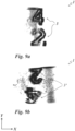
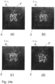
- the security element has the number 4 and the number 2, then if the security element is tilted and/or bent and/or rotated, the number 4 can change into the number 2 and/or vice versa.
- the security element may comprise only one track. If the track is illuminated with a light source, an observer can preferably detect an image point which, when the security element is rotated and/or bent and/or tilted about any axis, has at least one movement effect, in particular at least one movement effect dependent on an illumination and/or viewing angle, along the path.
- the security element preferably comprises a plurality of tracks comprising a plurality of first microstructures. As already explained above, this makes it possible for an observer to detect a number of pixels that correspond in particular to the number of tracks and that provide one or more image elements.
- the security element is also possible for the security element to be designed to be illuminated with a plurality of light sources.
- a number of image points corresponding to the plurality of light sources is typically provided per track and/or per first microstructure, which together provide one or more image elements that can be detected by an observer.
- optical effects described above occur multiple times when illuminated simultaneously with different point light sources. It is also possible that when irradiated at different angles with different point light sources, different optically variable effects are generated by the security element, whereby the security element provides further security features that are difficult to forge, and in particular so-called "second line” security features.
- a web is understood to mean in particular a flat area with a width, preferably with a constant width, which has at least follows a curve that is curved in sections, preferably an elliptical, circular, spiral and/or circular arc-shaped curve, wherein the curve can in particular be open or closed, in particular a partial area of a closed curve.
- the path and/or one or more contours of the path follow a curve that is curved on one side, so that preferably the sign of the curvature is the same everywhere, so that in particular the curvature of at least one curve does not change the sign.
- a curvature is understood in particular to be a local deviation of a curve from a straight line.
- the curvature of a curve is understood in particular to be a change in direction per length and/or distance traveled over a sufficiently short curve section or curve course.
- the curvature of a straight line is zero everywhere.
- a circle with a radius r has the same curvature everywhere, namely 1/r.
- the curvature changes from curve point to curve point, in particular the curvature changes continuously from curve point to curve point, so that the curves in particular do not have any kinks and/or discontinuities.
- the curvature of a curve at a point P therefore indicates how much the curve deviates from a straight line in the immediate vicinity of point P.
- the amount of the curvature is called the radius of curvature and this corresponds to the reciprocal of the amount of a local radius vector.
- the radius of curvature is the radius of the circle that best approximates the point of contact and/or tangency P of a curve in a local neighborhood.
- the curvature of two or more tracks, in particular circular tracks or circular tracks and/or elliptical tracks, can be the same.
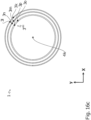
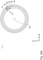
- two or more tracks, more preferably circular tracks or circular tracks and/or elliptical tracks, each comprising one or more first microstructures can have different curvatures, in particular a pronounced 3D effect, more preferably a 3D effect in combination with a strong achromatic movement effect, wherein the two or more paths, preferably circular paths or circular paths and/or elliptical paths, each comprising one or more first microstructures, can be spaced apart from one another.
- the width of one or more of the tracks is advantageously between 3 ⁇ m and 300 ⁇ m, preferably between 10 ⁇ m and 100 ⁇ m.
- the width of one or more webs may change depending on the direction of travel of the respective web.
- the width changes continuously and/or discontinuously at least in sections along the direction of travel of the respective web.
- the width of the respective web is preferably determined by the distance between the longitudinal edges of the respective web.
- At least 50%, preferably 70%, particularly preferably 90% of all webs of a plurality of webs can each form at least one fifth, preferably at least one quarter, particularly preferably one third, especially preferably half of a closed web.
- At least 50%, preferably 70%, particularly preferably 90% of all tracks of a plurality of tracks can each form at least a quarter circle, preferably at least a third circle, particularly preferably a semicircle.
- the curvature of one or more of the tracks is between 0.02 mm -1 and 2 mm -', preferably between 0.1 mm -1 and 1 mm -1 , or the radius is between 0.5 mm and 50 mm, in particular between 1 mm and 10 mm.
- one or more of the tracks can have the same, in particular the same curvature everywhere, in particular at every location of the respective track, more preferably at every point of the respective track.
- the curvatures of two or more tracks are each the same.
- one or more of the tracks, in particular all tracks, more preferably all circular and/or elliptical tracks to have different curvatures from one another.
- the curvature of one or more of the paths, in particular of all paths, does not change sign over the entire course of the respective paths.
- the radius and/or the curvature and/or the radius of curvature of one or more of the tracks may change depending on the direction of travel of the respective track.
- this change is continuous or discontinuous, at least in sections, along the direction of travel of the respective track.
- the width of one or more of the tracks is smaller than the radius or radii of the respective tracks and/or smaller than the radii of curvature of the respective track.
- an associated first microstructure is provided in each of the tracks or in each of the sections of a track.
- the entire surface area of the respective track or the respective section is covered with the associated first microstructure.
- the associated first microstructure is preferably not provided outside the surface area of the respective track or the respective section of a track.
- the associated first microstructure runs along the associated path or the associated section of a path. This means that at least one structural parameter of the associated first microstructure changes depending on a parameter of the path, in particular the local tangential orientation and/or width of the path and in particular the longitudinal extension of the structural elements of the first microstructure has a constant angle to the tangential orientation of the associated path.
- At least one alignment, longitudinal extension and/or preferred direction of the first microstructure and/or the structural elements of the first microstructure follows the associated path or the contour of the associated path.
- the alignment, longitudinal extension and/or preferred direction of the microstructure is preferably oriented parallel to the direction of travel of the path and/or the contour of the path at every point on the path and/or includes a predetermined offset angle with these.
- the local alignment of one or more structural parameters of the underlying first microstructure is thus preferably aligned with the respective local tangential alignment of the respective path.
- the local tangential alignment of one or more structural parameters of one or more of the first microstructures can preferably have the same angle to a local curvature radius vector as the respective path, where "local" refers to the same location, in particular the same point on the respective path, at which the local alignment and the local curvature radius vector are considered.
- the one or more second microstructures are preferably each provided in a surface area which does not overlap with the tracks.
- the surface areas in which the one or more second microstructures are provided are preferably designed in the form of a pattern, in particular as alphanumeric characters, patterns, as a graphic motif or as a portrait.
- the second microstructures can be provided in a surface area that consists of two or more sub-areas that are spaced apart from one another and are each formed in the shape of a strip, in particular with a width of less than 300 ⁇ m.
- One or more of the sub-areas can each overlap an associated interruption area of the one or more tracks, at least in some areas.
- one or more of the second microstructure elements of the respective one or more second microstructures can each be formed as one or more relief structures, in particular as one or more surface reliefs, preferably as one or more oval or round lenses, more preferably as one or more free-form surfaces with one or more lens effects, particularly preferably as one or more freely and/or circularly shaped Fresnel lenses.
- One or more of the second microstructures preferably provide a relief image that appears three-dimensionally, in particular a relief image that appears three-dimensionally achromatic.
- the respective second microstructures preferably have a plurality of second facet surfaces, the Course and/or inclination angle course is determined such that the relief image is provided by reflection and/or diffraction of the incident light.
- HRI High Refractive Index
- One or more of the first and/or second microstructures can be converted into a volume hologram by holographic exposure or molded as relief structures.
- one or more of the first and/or second microstructures can each comprise a plurality of first and second microstructure elements, respectively, which are each characterized in particular by the parameters of spacing of the microstructure elements, relief depth, relief shape, orientation of the longitudinal direction of the microstructure elements.
- one or more of the first and/or second microstructures can be designed as a grid, in particular as a sinusoidal or rectangular or triangular grid.
- a sinusoidal grating advantageously produces two equally intense diffraction patterns, preferably in the -1st and +1st diffraction orders, although higher diffraction orders can also occur.
- one or more of the first and/or second microstructures can be designed as one or more sawtooth-shaped microstructures, in particular as a blaze grating.
- a blaze grating advantageously diffracts incident light mainly into a first diffraction order, preferably into a +1st or -1st diffraction order.
- a single light source in particular a point light source, only a diffraction pattern with high intensity, preferably with higher intensity than in the other diffraction order, is visible.
- Higher intensity means that the intensity in one diffraction order, for example the -1st diffraction order, is in particular at least a factor of 2, preferably a factor of 3, greater than in another diffraction order, for example the +1st diffraction order.
- one or more of the first microstructures in particular the blaze gratings, can each be superimposed with at least one finer structure, for example a subwavelength grating, wherein the achromatic diffraction of the first microstructures preferably becomes monochromatic.
- a superposition with high-frequency subwavelength cross gratings can take place.
- the periods, in particular grating periods, or the spacing of the microstructure elements of one or more of the first and/or second microstructure elements are advantageously between 0.2 ⁇ m and 50 ⁇ m, preferably between 0.3 ⁇ m and 20 ⁇ m, particularly preferably between 2 ⁇ m and 10 ⁇ m.
- the depth, in particular the relief depth, of one or more of the first or second microstructures is typically between 50 nm and 15 ⁇ m, advantageously between 50 nm and 5000 nm, preferably between 100 nm and 3000 nm.
- the first or second microstructures diffract and/or scatter the incident light in a narrower angular range, in particular in an angular range between +10° and -10°, around the directly reflected light, ie the light of the zeroth diffraction order.
- the relief shape of one or more of the first or second microstructure elements is preferably sinusoidal, triangular, sawtooth-shaped and/or trapezoidal.
- one or more of the first or second microstructure elements can each have a linear shape and in particular be formed in the form of grid lines, which preferably have a triangular cross-section.
- one or more of the linear microstructure elements in particular grid lines, can each have a length between 50 ⁇ m and 100 mm, preferably between 0.5 mm and 50 mm, and in particular between 2 mm and 20 mm and/or the length of one or more of the linear microstructure elements, in particular the grid lines, can be at least a factor of 5 and preferably a factor of 10 greater than the grid period and/or the spacing of the respective linear microstructure element, in particular the respective grid line, from the respective adjacent grid line.
- one or more of the first or second microstructures can each be designed as one or more anisotropically scattering structures, in particular as anisotropic matt structures, which have a greater scattering power and/or a larger scattering angle for the incident light when viewed along a preferred direction compared to when viewed in a direction transverse and/or perpendicular to the preferred direction.
- the average distance between one or more of the first microstructure elements of the one or more anisotropically scattering structures is in each case between 0.5 ⁇ m and 10 ⁇ m, particularly preferably between 0.8 ⁇ m and 5 ⁇ m.
- the mean distance of a structure is defined as the mean value of the distances between adjacent local maxima and/or local minima of a structure, in particular of a respective matte structure.
- At least three, preferably at least five, grating periods of one or more of the first microstructures and/or at least three, preferably at least five, average spacings of one or more of the first microstructures can be arranged in the respective one or more tracks.
- first and/or second microstructure elements of the first or second microstructure each have at least one first or second facet surface, which preferably forms one or more predominantly refractive microstructures, for example micromirrors.
- the first or second facet surfaces each have a smallest surface dimension between 10 ⁇ m 2 and 5000 ⁇ m 2 , in particular between 25 ⁇ m 2 and 900 ⁇ m 2 .
- the first or second facet surfaces preferably each have an angle of inclination to the surface normal of the security element between 1° and 45°, in particular between 1° and 20°.
- the first or second facet surfaces preferably have a flat surface or a convex or concave curved surface.
- One or more of the second microstructure elements made up of first or second facet surfaces preferably represent at least one, preferably achromatic, three-dimensional representation of a relief image.
- the angle of inclination of the first or second facet surfaces is preferably between 1° and 45°, in particular between 1° and 20°.
- the period and/or the inclination of one or more of the first or second facet surfaces preferably changes continuously along one or more lateral dimensions.
- one or more structural parameters of one or more of the microstructure elements of the first microstructure can each change continuously and/or steadily along the respective one or more paths, wherein one or more of the structural parameters can preferably each be selected from: spacing of the first microstructure elements, relief depth, orientation of the longitudinal direction of the first microstructure elements, preferred direction, average spacing of the first microstructure elements, inclination angle of the first facets.
- orientation of one or more first microstructure elements of the respective first microstructure and/or the preferred direction and/or the angle of inclination of one or more first facets of the respective first microstructure can preferably each follow one or more contours of the respective path, which are determined in particular by one of the longitudinal edges of the respective path or by the area centroid line of the respective path.
- the local orientation of one or more first microstructure elements of the respective first microstructure or the local preferred direction of one or more first facets of the respective first microstructure can each correspond to the local curvature of the respective track, which can be determined in particular by one or more of the longitudinal edges of the respective one or more tracks and/or by the one or more area centroid lines of the respective one or more tracks.
- the local orientation of one or more first microstructure elements of the respective first microstructure or the local preferred direction of one or more first facets of the respective first microstructure may not differ from the local curvature of the respective track by more than 0° to 30°, wherein the local curvature is defined in particular by one or more longitudinal edges of the respective track or can be determined by one or more centroid lines of the respective trajectory.
- the local orientation of one or more first microstructure elements of the respective first microstructure or the local preferred direction of one or more of the first facets of the respective first microstructure can each differ from the local curvature of the respective track by a predetermined deviation angle of up to a maximum of ⁇ 30°, wherein the local curvature can be determined in particular by one or more longitudinal edges of the respective track or by one or more area centroid lines of the respective track.
- the local orientation of one or more first microstructure elements of the respective first microstructure or the local preferred direction of one or more facets of the respective first microstructure can each have an angle between -45° and +45°, preferably an angle between -30° and +30°, more preferably an angle between -15° and +15°, to the local curvature of the respective track, wherein the local curvature can be determined in particular by one or more longitudinal edges of the respective track or by one or more area centroid lines of the respective track.
- the longitudinal extension of one or more first microstructure elements of the respective first microstructure and/or the preferred direction can each run parallel or perpendicular to the respective track, relative to the plane spanned perpendicular to the surface normal of the security element, in particular each run parallel or perpendicular to one or more longitudinal edges of the respective track or one or more surface centroid lines of the respective track.
- the above-mentioned partial area of one or more of the tracks comprises at least 50% of the respective track, particularly preferably at least 70% of the respective track, especially preferably at least 85% of the respective track.
- a security element is illuminated by at least one radiation source, in particular a light source, preferably a point-shaped light source, only one point and/or one location of the respective track scatters and/or diffracts and/or reflects light, so that an image element provided thereby, in particular at least one image point, provides at least one movement effect when the security element containing the track is tilted and/or bent and/or rotated to the left and/or right and/or forwards and/or backwards, in particular about any axis.
- one or more of the tracks and/or one or more of the first microstructures can intersect in one or more intersection areas, wherein one or more of the tracks can intersect once or twice or several times and/or one or more of the tracks can intersect in pairs with different frequencies.
- the track pairs B1 and B2, B2 and B3, and B1 and B3, each selected from a set of three tracks B1, B2 and B3, can each intersect with each other with different frequencies.
- a number of three closed and/or open paths B1, B2 and B3 can intersect such that paths B1 and B2 intersect twice, paths B1 and B3 intersect four times and paths B2 and B3 intersect only once.
- a track can also intersect itself. Preferably, the tracks do not intersect themselves.
- first microstructures of two or more, in particular of all, intersecting paths in the cutting area are provided.
- the first microstructure or the first microstructures of the intersecting paths are provided in a one- or two-dimensional grid, the grid width being in particular between 10 ⁇ m and 300 ⁇ m.
- This rasterization of different initial microstructures is referred to below as a mosaic surface.
- each track and/or first microstructure running through a cutting region can be assigned an equal proportion of the area of the cutting region, so that in the cutting region each track is provided with the same proportion, in particular area proportion.
- each of the two tracks and/or the two first microstructures in the intersection area is preferably assigned an area, in particular an area share of 50% of the area of the intersection area.
- each of three, generally n, intersecting tracks and/or first microstructures can be assigned a An area share of one third, generally 1/n, of the cutting area can be assigned.
- one or more surface areas are provided which are provided with one of the first microstructures of the tracks intersecting in the respective intersection area.
- the one or more surface areas are preferably arranged less than 150 ⁇ m, more preferably less than 50 ⁇ m, away from the respective intersection area. This distance is determined by the distance between the closest outer edges of the intersection area and/or the area in the intersection area of the intersecting tracks and the closest outer edge of the respective surface area.
- Such a design can effectively increase the available area for the first microstructures of the intersecting paths in the intersection area without negatively affecting the optical appearance. This can avoid interruptions in sequences of movement, morphing and/or flipping effects, which are provided by the intersecting paths in the respective intersection area, or at least make them less noticeable visually.
- At least one of the tracks and/or at least one of the first microstructures can have at least one interruption.
- the first microstructure or the first microstructures of the respective tracks are preferably not provided or not continued.
- the interruptions make it possible to superimpose the effects provided by the first microstructures with further optical effects of the security element and thus further increase the security element's protection against counterfeiting.
- the interruptions of the tracks preferably have dimensions below the resolution of the human eye with respect to their extension in the longitudinal direction of the respective tracks and preferably have a lateral extension in this direction of between 0.5 ⁇ m and 200 ⁇ m, more preferably between 1 ⁇ m and 100 ⁇ m.
- At least one interruption of at least one track and/or at least one first microstructure can be present in at least one intersection region of two or more tracks and/or two or more first microstructures.
- At least one interruption of at least one track and/or at least one first microstructure is present outside an intersection region of two or more tracks and/or two or more first microstructures.
- the interruptions are preferably distributed randomly and/or pseudo-randomly.
- one or more of the interruptions can be distributed randomly and/or pseudo-randomly parallel and/or perpendicular to one or more tangential vectors of the respective path.
- At least one track and/or at least one first microstructure may have at least one offset.
- An offset is present when two parts and/or sub-areas and/or sections of at least one track and/or a first microstructure are arranged offset from one another, in particular displaced relative to one another, wherein the size of the offset, in particular displacement, can be as large as desired.
- one or more of the lateral dimensions of an offset may each be smaller than the width of the respective web.
- At least one path and/or a first microstructure can have at least one offset, wherein the at least one offset can be distributed in particular randomly and/or pseudo-randomly over the arc length, preferably a part of the arc length, of the at least one path and/or a first microstructure. More preferably, the offsets, in particular the size of the offset and/or the displacement, can be distributed randomly and/or pseudo-randomly. In particular, one or more of the offsets can each be distributed randomly and/or pseudo-randomly parallel and/or perpendicular to one or more tangential vectors of the respective path.
- Such an offset can be provided by at least one cut, in particular at least one straight cut, through at least one path and/or a first microstructure and the subsequent displacement of the at least one path and/or first microstructure cut in this way relative to the path and/or first microstructure.
- the angle of the at least one cut in particular the at least one cutting angle, can be arbitrarily aligned, in particular arbitrarily aligned to an orientation and/or to a longitudinal extent of the at least one cut web and/or first microstructure, so that the at least one web and/or first microstructure cut by at least one cut and the at least one web and/or first microstructure do not merge flush into one another.
- adjacent parts of a cut of at least one cut web and/or a first microstructure can be arranged displaced relative to one another, in particular perpendicular to an orientation and/or to a longitudinal extension of the at least one web and/or first microstructure.
- an offset can provide a reduction of unwanted chromatic diffraction, so that in particular an improved achromatic appearance and thus an improved sequence of image elements can be provided.
- a partial area and/or a section of a web and/or a first microstructure can be offset by two cuts in the same direction, in particular by two cuts arbitrarily aligned with one another, more preferably by two cuts aligned parallel to one another, at different locations, in particular positions on the web and/or the first microstructure, and a shift and/or offset of the partial area of the web and/or the first microstructure cut out in this way, relative to the uncut web and/or first microstructure, in order in particular to produce an offset of a partial area and/or section of a web and/or first microstructure.
- At least the offset, in particular the size of the offset and/or the shift can be less than a width of a track and/or a first microstructure.
- an offset, in particular the size of the offset and/or the shift can correspond to the width of a track.
- the offset, in particular the size of the offset and/or the shift is not more than five times the width of a track and/or a first microstructure, whereby in particular jumps in the effects of movement, morphing and/or flip effects, preferably of one or more image elements, of the first microstructures can be avoided.
- an offset, in particular the size of the offset and/or the shift is on average between 1% and 50%, preferably between 2% and 20%, of the width of one or more tracks and/or first microstructures.
- a file which comprises one or more spatial arrangements of pixels of one or more image elements.
- one or more at least partially curved tracks and/or one or more at least partially curved sections of one or more tracks are determined from the spatial arrangement of the pixels.
- one or more first microstructures are provided in each of the one or more tracks or sections of tracks, which provide first optically variable information when exposed, in particular provide one or more 3D effects and/or movement effects when tilting and/or bending and/or rotating the security element, preferably provide achromatic or monochromatic 3D effects and/or movement effects.
- the tracks with the microstructures can be created, for example, by means of electron beam lithography or laser lithography in a master substrate.
- the structures of such a master substrate can then be copied into a metal substrate, in particular made of nickel, in a galvanic process.
- a metal substrate in particular made of nickel, in a galvanic process.
- a sequence of image elements can be defined in the file in order to be able to determine the paths and/or path sections in such a way that the desired sequence of image elements is generated by the movement of the image points along the paths when tilting and/or bending and/or rotating the security element.
- a sequence of image elements can be defined in the file, so that an unrecognizable image, for example a random or pseudorandom arrangement of points and/or a cloud-like Distribution of dots, when tilting and/or bending and/or rotating the security element, a recognizable image, for example a denomination, is generated by the movement of the pixels along the paths.
- an unrecognizable image for example a random or pseudorandom arrangement of points and/or a cloud-like Distribution of dots
- the first and/or second microstructures are preferably molded into the same or two different layers of the security element using a replication process.
- These layers are preferably lacquer layers which have a layer thickness preferably in the range between 1 ⁇ m and 10 ⁇ m. It is also possible for these layers to be a carrier film of the security element, in particular a PET film.
- One or more additional layers which lie above the replication layer from the visible side of the carrier film, can be color layers, in particular opaque, translucent or transparent color layers. These color layers are preferably applied or formed in a pattern.
- the replication layer can also be a translucent or transparent color layer.
- One or more further layers can be arranged on the carrier film of the security element, wherein in particular one or more of the further layers are selected from: release layer, protective layer, adhesive layer, non-adhesive layer, barrier layer, adhesive layer.
- the one or more layers of the security element in which the first and/or second microstructures are molded are further preferably coated with one or more reflective layers which cover the one or more first and/or second microstructures at least in regions.
- These reflective layers are preferably metallic reflective layers, for example made of aluminum (Al), copper (Cu) or silver (Ag) and/or high-refractive-index layers, so-called HRI layers, for example TiO 2 or ZnS.
- the one or more layers of the security element in which the one or more first and/or second relief structures are formed can be coated or printed with one or more color layers, in particular translucent or transparent color layers. These color layers are preferably applied or formed in a pattern. They preferably have different colors.
- the one or more layers in which the first and/or second microstructures are formed can each be coated or printed with one or more colors and/or layers that change depending on the viewing angle, for example coated with cholesteric liquid crystal layers and/or with layers containing color-changing pigments.
- the layers that generate color changes can consist of an interference layer system.
- this interference layer system can be a three-layer system consisting of a semi-transparent absorber layer, a dielectric spacer layer and a semi-transparent or opaque mirror layer.
- the above-mentioned coatings can be combined with one another in any form.
- several of the above-mentioned coatings can follow one another on one or both sides of a layer provided with one or more of the first and/or second relief structures, and these can each be formed in a pattern. This makes it possible to achieve interesting optical effects, in particular color effects, which further improve the security element's protection against counterfeiting.
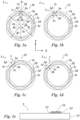
- Figures 1a to 1e illustrate the structure of a security document 5 with a security element 1.
- Fig. 1a to 1d show the security element 1 in plan view and Fig. 1e applied in cross-section to a document body or to a security document 5.
- the security document 5 preferably consists of an ID document, such as a passport, passport card, visa or access card. However, it may also be another security document 5, such as a banknote, a security or a credit or debit card.
- the security document 5 comprises a document body 51 and one or more security elements, of which Fig. 1a to 1e the security element 1 is shown.
- the security elements can be applied to the document body 51 of the security document 5 or embedded in the document body 51 of the security document 5, in particular completely or partially embedded.
- the document body 51 of the security document is preferably multi-layered and comprises in particular a carrier substrate which is formed from a paper substrate and/or plastic substrate.
- the document body 51 can also comprise one or more protective layers, one or more decorative layers and/or one or more security features.
- the document body 51 can also comprise further layers, for example one or more release layers, adhesive layers, non-stick layers, barrier layers and/or adhesive layers.
- the document body 51 preferably comprises Document body 51 also includes an electronic circuit, in particular an RFID chip, in which information is stored.
- the document body 51 can have a window area, wherein the window area can be designed as an opening in the document body 51 and/or as a transparent area of the document body 51.
- the security element 1 can be arranged overlapping the window area and can thus be visible from both sides of the security document 5.
- the security element 1 is formed in particular by the transfer layer of a transfer film, by a laminating film and/or by a film element, in particular in the form of a security patch or in the form of a security strip or in the form of a security thread.
- the security element 1 can cover a surface of the security document 5 completely and/or only partially, for example be designed in the form of a strip or patch, as is the case with regard to the security element 1 in Fig. 1e shown.
- the security element 1 preferably has a protective layer 54, a decorative layer 52 and an adhesive or bonding layer 53.
- the security element 1 is designed in the form of the transfer layer of a transfer film, which comprises a protective layer 54, a decorative layer 52 and an adhesive layer 53 and is applied to the front of the document body 51 as in Fig. 1e shown is applied.
- the decorative layers 52 of the security element 1 form one or more security features, which are preferably also visually visible to the human observer.
- the decorative layers 52 comprise one or more of the following layers:
- the decorative layer 52 has one or more layers, each of which has one or more first and/or second microstructures.
- the one or more first or second microstructures can be converted into a volume hologram in the respective layer by holographic exposure. However, they can also be designed as a relief structure which is molded into a surface of the respective layer. These layers are therefore preferably a layer made of a photopolymer in which areas with different refractive indices are provided for generating a volume hologram, or a lacquer layer or plastic film in which the surface relief of the microstructure is molded by a replication process.
- the microstructures are preferably diffractive structures, such as rectangular diffraction gratings, sinusoidal diffraction gratings or zero-order diffraction structures.
- the microstructures can also be isotropic and/or anisotropic matt structures, triangular blaze gratings and/or structures that essentially act in reflection, such as microlenses, microprisms or micromirrors.
- the one or more first microstructures are preferably provided in one or more at least partially curved paths, of which in the figures Fig. 1a to Fig. 1d several tracks 2a to 2e are shown. Furthermore, it is also possible that one or more of the first microstructures are in one or more at least partially curved sections of a track, for example sections of the Figures 1a to 1d shown paths are provided. It is also possible that one or more of the first microstructures each run along one or more at least partially curved paths or run along one or more at least partially curved sections of a path.
- the decorative layer 52 preferably has one or more metallic layers, which are preferably not provided over the entire surface, but only partially in the security element.
- the metallic layers can be opaque, translucent or transmissive.
- the metallic layers are preferably formed from different metals which have a significantly different reflection and/or transmission spectrum.
- the metal layers are formed from aluminum, copper, chromium, gold, silver or an alloy of these metals.
- the one or more metal layers are preferably structured in a pattern, preferably in the form of alphanumeric characters and/or as graphics and/or as complex representations of objects.
- the decorative layer 52 can further comprise one or more color layers, preferably transparent or translucent color layers. These color layers are preferably color layers which are applied by means of a printing process and which have one or more dyes and/or pigments which are incorporated in a binder matrix.
- the decorative layer 52 further preferably has one or more interference layers which reflect or refract the incident light in a wavelength-selective manner.
- These layers can be formed, for example, by thin-film elements which generate a viewing angle-dependent color shift effect based on an arrangement of layers which have an optical thickness in the range of half or a quarter of the wavelength of the incident light.
- These layers typically comprise a dielectric spacer layer, in particular arranged between a semi-transparent absorber layer and a semi-transparent or opaque mirror or reflection layer, or can preferably be formed by a layer comprising thin-film layer pigments.
- the decorative layer 52 can further preferably have one or more liquid crystal layers, which on the one hand generate a polarization of the incident light and also a wavelength-selective reflection and/or transmission of the incident light depending on the orientation of the liquid crystals.
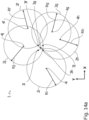
- Fig. 1a shows a section of the security element 1 comprising the mutually offset curved tracks 2a, 2b, 2c, 2d, 2e, wherein the tracks have the radii R a , R b , R c , R d , R e .
- the centers 4a, 4b, 4c, 4d, 4e of the paths are arranged in the geometric centers of the paths 2a, 2b, 2c, 2d, 2e and are spaced from all points on the circular paths 2a, 2b, 2c, 2d, 2e by the radii R a , R b , R c , R d , R e , so that the curvature of the paths 2a, 2b, 2c, 2d, 2e is respectively 1/R a , 1/R b , 1/R c , 1/R d , 1/R e .
- the plane in which the orbits lie, or have a spatial extension is spanned by a two-dimensional coordinate system, which is described by the basis vectors x and y, whereby the vectors x and y are preferably perpendicular to each other, as in Fig. 1a shown.
- coordinate systems with more than two dimensions and/or coordinate systems on at least one curved path can also be selected.
- the radii of the paths 2a to 2e can also differ.
- at least one of the paths 2a to 2e can have a variable curvature, preferably when the path is not circular but, for example, elliptical and/or spiral and/or circular arc-shaped.
- the paths 2a to 2e can further preferably be continuous and/or differentiable and/or integrable curves, wherein the paths 2a to 2e are not necessarily one-dimensional curves, but preferably can also be two-dimensional curves, such as a portion of a spherical surface.
- the tracks 2a to 2e can also be designed as closed tracks and/or from at least a partial area of a closed track.
- at least 50%, preferably 70%, particularly preferably 90% of all tracks can each form at least a fifth, preferably at least a quarter, particularly preferably at least a third, particularly preferably at least half of a closed track.
- at least 50%, preferably 70%, particularly preferably 90% of all tracks can each form at least a quarter circle, preferably at least a third of a circle, particularly preferably a semicircle.
- the tracks 2a, 2b, 2c, 2d, 2e in the Figures 1a to 1d are designed as two-dimensional circular curved curves in the embodiment shown there and are shown as dashed lines.
- the sign of the curvature of the curved paths does not change, in particular in the case of circular paths or circular paths, and is constant.
- the curvature of a path is more preferably between 0.02 mm -1 and 2 mm-', preferably between 0.01 mm -1 and 1 mm -1 .
- at least one path, in particular at least one circular path can have the same curvature everywhere.
- the curvature of all paths 2a to 2e, in particular all circular paths or circular paths can be the same, as in Fig. 1a to Fig. 1d shown.
- the curvature of the tracks 2a to 2e can be different from one another.
- the first microstructures which are provided in the tracks 2a to 2e, provide a first optically variable information.
- the first optically variable information has one or several image elements, each of which is composed of several pixels.
- the first microstructures which are provided in the tracks 2a to 2e, generate in the embodiment according to Fig. 1a to 1d a picture element 3, which is formed in particular from an arrangement of pixels 3a, 3b, 3c, 3d, 3e.
- the security element 1 preferably provides an observer with one or more picture elements 3, wherein at least one picture element 3 can be formed as a motif, for example.
- the image points 3a, 3b, 3c, 3d, 3e are each generated by the first microstructures of the tracks 2a, 2b, 2c, 2d and 2e respectively.
- the image points 3a, 3b, 3c, 3d, 3e move along the respectively assigned track when the security element 1 is tilted and/or bent and/or rotated, when illuminated with at least one light source, preferably with a point light source.
- the pixels 3a to 3e of the pixel 3 can have a point-shaped, in particular circular disk-shaped, shape, as in Fig. 1a to 1d However, it is also possible that they have a different shape, for example an elliptical shape.
- Image element 3 in the Figure 1a is detectable or visible to an observer when the tracks 2a, 2b, 2c, 2d, 2e are illuminated by a light source, whereby the tracks are designed in such a way that only one pixel per track is visible to the observer.
- the pixels 3a, 3b, 3c, 3d, 3e that are visible in this way provide the image element 3 due to their arrangement on the tracks and the constant distances from one another.
- the image element 3 can move along the tracks 2a, 2b, 2c, 2d, 2e when viewed by an observer if the security element 1 comprising the tracks is oriented relative to the observer and/or the radiation source is tilted and/or bent and/or rotated and/or inclined.
- the image element 3 moves depending on the direction of the tilting and/or bending and/or rotation and/or inclination of the security element 1 relative to the observer in one of the two possible directions of movement per path, in particular degrees of freedom of movement, along the paths.
- the image element 3 moves as an arrangement of the Fig. 1a shown five image points 3a to 3e along the five paths 2a, 2b, 2c, 2d, 2e, so that the Fig. 1a shown arrangement of the pixels 3a, 3b, 3c, 3d, 3e relative to one another is maintained when the security element 1 is tilted and/or bent and/or rotated and/or the orientation with respect to the Figures 1a to 1d shown coordinate system, spanned by the vectors x and y, does not change.
- the rotation of the security element 1 is understood to mean the rotation of the security element 1 around the surface normal of the security element 1, which is perpendicular to the plane spanned by the vectors x and y.
- the tilting of the security element 1 is understood to mean the tilting of the security element 1 around an axis which lies in the plane spanned by the vectors x and y.
- the image element 3 can, during rotation and/or bending and/or tilting of the security element 1, in particular the orientation of the image element 3 relative to an axis along and/or parallel to the vectors x and/or y of the Fig. 1a to 1d shown coordinate system, preferably continuously, so that a continuous or discontinuous movement effect is provided for the observer. Further preferably, the image element 3 can change the orientation of the image element 3 with respect to an axis during a rotation and/or bending and/or tilting of the security element 1 parallel and/or along the vectors x and/or y of the Fig. 1a to 1d shown coordinate system is kept constant.
- the Figures 1a to 1d show in any sequence a movement effect of the image element 3 comprising the five pixels 3a, 3b, 3c, 3d, 3e, wherein the center 30 of the image element 3 is at the position of the pixel 3c in the Fig. 1a to position 31 in the Fig. 1b , further to position 32 in the Fig. 1c and finally to position 33 in the Fig. 1d
- the direction of movement of the picture element 3 can preferably be chosen arbitrarily in order to provide various movement effects.
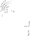
- the Figure 2a shows a section of the security element 1 comprising a portion 20 of a curved track 2 with a width B and the radius R.
- the curved track 2 can in particular be one of the tracks 2a to 2e according to Fig. 1a to 1e act.
- the Figure 2a a pixel 3a, wherein the pixel 3a is preferably located on the track and can preferably move along the track, so that a movement effect, in particular a continuous movement effect, is generated for a viewer.
- a section A ⁇ A' is shown, which runs in particular radially to the center of a closed, preferably circular and/or elliptical path, wherein the section runs in the radial direction through the path.
- a two-dimensional coordinate system is shown by two vectors x and y arranged perpendicular to each other in the Fig. 2a which spans the plane in which track 2 lies or is embedded.
- the web 2 can have a width B between 2 ⁇ m and 300 ⁇ m, in particular between 5 ⁇ m and 150 ⁇ m, more preferably between 10 ⁇ m and 100 ⁇ m.
- the area of the path depends on the arc length of the path and the width of the path.
- the width of the path can be constant or change along the path.
- the width of the path does not change with the course of the path, in particular the course of an azimuth angle ⁇ with respect to the coordinate system with the basis vectors x and y.
- An inner contour 20a corresponds to an inner edge of the track 2 and/or of a partial area of a track, preferably with an inner radius R i .
- the outer contour 20b of the track 2 and/or of the partial area of a track corresponds to an outer edge of the track, which preferably has an outer radius R a .
- the inner contour is arranged on the side of the track that points in the direction of the center M of a circle that is determined by the radius of curvature vector, while the outer contour 20b of the track is arranged on the side 20a of the track pointing away from the radius of curvature vector.
- a perpendicular S is drawn, which is perpendicular to a tangential vector T, which hugs the outer edge of the track.
- the direction of the tangential vector T is aligned perpendicular to the radius vector R in the present embodiment.
- the curvature of an inner contour at a specific azimuth angle ⁇ of the track 2 and/or of the partial area of a track is preferably always greater than the curvature of an outer contour at this azimuth angle ⁇ .
- the distance between a specific location and/or a specific point at a specific azimuth angle ⁇ on an outer contour and the same location and/or the same point at the specific azimuth angle ⁇ on an inner contour preferably corresponds to the width of the track 2, in particular the width of the track 2 dependent on the location and/or the point at the specific azimuth angle ⁇ .
- the Figure 2c shows an embodiment of the first microstructures 10 as a blaze grating 10d.
- the first microstructure can in particular also be designed as a sawtooth-shaped grating and/or triangular grating.
- the first microstructures 10 in particular of the Figures 2b and 2c a period or grating period ⁇ between 0.2 ⁇ m and 50 ⁇ m, preferably between 0.3 ⁇ m and 20 ⁇ m, more preferably between 2 ⁇ m and 20 ⁇ m and particularly preferably between 3 ⁇ m and 10 ⁇ m, and/or a grating depth between 50 nm and 15000 nm, advantageously between 50 nm and 5000 nm, preferably between 100 nm and 3000 nm.
- At least three, preferably at least five grating periods of the first microstructures 10 and/or at least three, preferably at least five average distances of the first microstructures 10 are arranged in the at least one web 2, in particular across the width of the web 2, and/or the at least one partial region of the web, in particular the width of the partial region of the web 2.
- the at least one first microstructure 10 can also consist of an arrangement of a plurality of micromirrors which are inclined relative to the plane spanned by the vectors x and y according to respective angles of inclination.
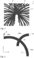
- the Fig. 3 shows a security element 1 comprising a plurality of curved, non-closed webs 2 and/or partial areas of webs, wherein Paths and/or sub-areas intersect and/or overlap in intersection areas 11.
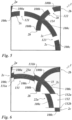
- the Fig. 4 shows a section of a security element 1 comprising three curved tracks 2a, 2b, 2c, wherein the tracks 2b and 2c intersect in particular in an intersection area 11.
- the Fig. 4 first microstructures 100a, 100b, 100c arranged along the respective paths 2a, 2b, 2c.
- the orientation of the first microstructures 100a, 100b, 100c and/or at least one structural parameter of the first microstructures 100a, 100b, 100c in particular the spacing of the microstructure elements, the relief depth, the orientation of the longitudinal direction of the microstructure elements, the preferred direction, the average spacing of the microstructure elements and/or the angle of inclination of the micromirrors, changes continuously and/or steadily along the respective path.
- the Fig. 4 shows, by way of example, the continuous change in the alignment of the longitudinal extension or the orientation of the longitudinal direction of the microstructure elements of the lattice structures 100a, 100b, 100c along the corresponding tracks 2a, 2b, 2c.
- the longitudinal extension of the lattice structures 100a, 100b, 100c is thus aligned at each point of the respective tracks 2a, 2b, 2c parallel to the tangential direction of the corresponding point of the respective tracks 2a, 2b, 2c.
- the lattice structures have a width of preferably seven lattice periods transverse to the tracks.
- the alignment and/or the longitudinal extent of the one or more first microstructures 100a, 100b, 100c of the one or more tracks 2a, 2b, 2c can follow a contour, in particular the inner contour, preferably the outer contour, of the tracks 2a, 2b, 2c.
- the alignment of the first microstructures at most points of the one or more tracks, preferably along the entire track can have the same angle to a curvature radius vector of the one or more paths.
- the alignment and/or longitudinal extent of the one or more first microstructures 100a, 100b, 100c can be predominantly perpendicular, in particular perpendicular to the curvature radius vector.
- the alignment, in particular the preferred direction, of the first microstructures 100a, 100b, 100c at most points, preferably at least 50% of the points, particularly preferably at 70% of the points, particularly preferably at 85% of the points, ideally for all points of the paths 2a, 2b and/or 2c, in particular in the case of one or more elliptical and/or circular paths, can be aligned equal to a perpendicular on the paths 2a, 2b, 2c, in particular perpendicular to one or more tangential vectors of the paths 2a, 2b, 2c.
- the tracks 2a, 2b and 2c intersect in a cutting area 11.
- the cutting area 11 shown corresponds geometrically to the area in which the curved paths 2b and 2c overlap and/or intersect, whereby in the embodiment of the Fig. 4 in the intersection region 11 of the webs 2b and 2c only the first microstructure 100c of the web 2c and not the first microstructure 100b of the web 2b is present.
- the Fig. 5 shows a security element 1 comprising three curved tracks 2a, 2b and 2c with first microstructures 100a, 100b and 100c, respectively, wherein the track 2b and the track 2c intersect in particular in an intersection region 124. Furthermore, the track 2b has interruptions 122 and 124. The first microstructure 100b is not provided in the interruption 122 and there is an interruption of the microstructure 100b in the intersection region 124. Furthermore, the track 2c has interruptions 121 and 123 in which the first microstructures 100c of the track 2c are not provided.
- one of the interruptions 121, 122, 123 and 124 can each correspond geometrically to the area in which the respective tracks 2a, 2b and/or 2c do not have any first microstructures 100a, 100b or 100c.
- the interruptions 121, 122, 123 and/or 124 of the respective tracks 2a, 2b or 2c can be distributed randomly and pseudo-randomly.
- the interruptions 121 to 124 can be distributed randomly and/or pseudo-randomly parallel and/or perpendicular to a corresponding tangential vector.
- the Fig. 5 The embodiment shown has a number of interruptions 121, 122, 123 which are arranged outside the intersection area 124 of the web 2b and the web 2c.
- the interruptions 121, 122 and/or 123 arranged outside the cutting areas 124 each make up between 0.1% and 30%, preferably between 1% and 10% of the area and/or the length of the tracks 2a, 2b and/or 2c.
- Such interruptions produce a scattering effect in addition to the optical effect of the microstructures, which overall leads to a more achromatic impression.
- the Fig. 6 shows an embodiment of the security element 1, which has three curved tracks 2a, 2b and 2c with first microstructures 100a, 100b and 100c, respectively, wherein the track 2c has two offsets 131, 132.
- the offset 131 runs parallel to the cutting edges 131a, 131b and the partial area 21a of the track is offset by the length of the offset 131 with respect to the viewing direction of the Figure 6 shifted downwards.
- the offset 132 runs parallel to the cutting edges 132a, 132b and the partial area 22a of the web is with respect to the viewing direction of the Figure 6 shifted to the left by the length of the offset 132.
- the displacement directions of the offsets 131, 132 are arranged in particular perpendicular to one another.
- the area of a partial area 21a, 22a displaced by the offsets 131, 132 depends on the width and/or the progression of the width over the progression of the partial areas 21a or 22a and/or the arc length of the partial areas 21a or 22a.
- the partial areas 21a or 22a have the width and/or the progression of the width of the original, uncut web 2c from which the partial areas 21a or 22a were taken or from which the partial areas 21a or 22a were displaced.
- the offsets 131, 132 of the tracks 2a, 2b, 2c and/or the first microstructures 100a, 100b, 100c can be randomly and/or pseudo-distributed, in particular arranged, and/or randomly and/or pseudo-randomly distributed and/or arranged parallel and/or perpendicular to a corresponding tangential vector.
- one or more offsets 131, 132 can be less than one or more widths of the tracks 2a, 2b, or 2c and/or the first microstructures 100a, 100b, or 100c.
- the offsets are shifted between 1 ⁇ m and 100 ⁇ m, in particular between 3 ⁇ m and 50 ⁇ m. Similar to the interruptions from Figure 5 The offsets also create an additional scattering effect, which overall leads to a more achromatic impression of the security element.
- Fig. 7 shows a security element 1 comprising three curved tracks 2a, 2b, 2c with first microstructures 100a, 100b, 100c, wherein the tracks 2b, 2c have a mosaic surface 14.
- the mosaic surface 14 is divided into a plurality of partial mosaic surfaces 141, 142, 143, 144, which contain first microstructures 100b, 100c of the tracks 2b, 2c, wherein the first microstructure of at least one partial mosaic surface differs from the remaining first microstructures in the partial mosaic surfaces.
- the mosaic surface 14 of the tracks 2b, 2c and/or the first microstructures 100b, 100c of the tracks 2b, 2c there is a mosaic-like arrangement, in particular a grid, of the first microstructures 100b, 100c. This has the effect that the interruption of the two tracks appears less noticeable to the observer.
- the Fig. 8 shows a security element 1 comprising three curved tracks 2a, 2b, 2c with first microstructures 100a, 100b, 100c, wherein the tracks 2b, 2c have a mosaic surface 14 in a cutting area 11, which is divided into a plurality of partial mosaic surfaces 141, 142, 143, 144 containing first microstructures 100b, 100c. Further shows Fig. 8 in the surface areas 15, in particular in the vicinity of the mosaic surface 14, an arrangement of partial mosaic surfaces 141a, 142a, 143a, 144a, wherein these partial mosaic surfaces 141a, 142a, 143a, 144a have first microstructures 100b, 100c.
- At least a first microstructure 100b or 100c of a partial mosaic surface 141, 142, 143, 144, 141a, 142a, 143a, 144a can differ from the first microstructures of the remaining partial mosaic surfaces.
- the surface areas 15 and thus also preferably the partial mosaic areas 141a, 142a, 143a, 144a are arranged less than 150 ⁇ m, preferably less than 50 ⁇ m, away from the mosaic area 14.
- These partial mosaic areas have the effect that the continuous movement effects of the paths 2b and 2c appear to be uninterrupted to the unaided human eye.
- the Figure 9a shows a security element 1 comprising a picture element 3, wherein the picture element 3 is composed of the numbers "4" and "2" and the number "4" is drawn from the viewing direction of the Figure 9a located above the number "2".
- the Figure 9b shows a security element 1 comprising a picture element 3 ⁇ , wherein the picture element 3' consists of a number 4 rotated by 180 degrees and a rotated number 2 and the number "2" rotated by 180 degrees from the viewing direction of the Figure 9b above the number "4" rotated by 180 degrees.
- the tracks and/or the first microstructures and/or the transitions of the tracks in the embodiment of the Figures 9a and 9b , along which the image element 3 is transformed into the image element 3' by a movement effect, are arranged in such a way that the paths and/or first microstructures enable a transformation, in particular a morphing, preferably a flip from the image element 3 to the image element 3'.
- the change or transformation of the image element 3' that can be detected by an observer is Fig. 9a shown image element 3 to that in the Fig. 9b shown image element 3' is provided by tilting and/or bending and/or twisting the security element 1 relative to a light source and/or an observer.
- the Fig. 10a shows schematically a security element 1 comprising an image element 3, wherein the image element 3 is designed as the number "5".
- Three exemplary image points 3a, 3b, 3c of the image element 3 can move to the positions 30, 31, 32 when the security element 1 is tilted and/or bent and/or rotated on the curved paths 2a, 2b, 2c or path sections in both directions of the paths 2a, 2b, 2c.
- the security element 1 when the security element 1 is tilted and/or bent and/or rotated, a viewer detects a continuous movement effect, wherein the image element 3 can move in particular continuously between the positions 30, 31, 32 in a specific direction R1 along the paths 2a, 2b, 2c and, when the tilting direction and/or bending direction and/or the rotation direction change, can provide a movement opposite to the specific direction R1, i.e. in the direction R2, and vice versa.
- the optical effect of tilting and/or bending and/or rotating the Fig. 10b The security element shown consists in the movement of the image elements 3 and 3 ⁇ shaped as the numbers "5", whereby an observer can gain a three-dimensional impression through the virtual movement of the image elements below or above the security element.
- the Figures 11a, 11b and 11c The curved paths 2a, 2b, 2c, 2d shown have different radii of curvature from one another, with the path 2a having a smaller curvature than the paths 2b, 2c, 2d.
- the Figures 11a, 11b and 11c the four image points 3a, 3b, 3c, 3d each in different positions 30, 31, 32 in the course of a movement on the corresponding paths 2a, 2b, 2c, 2d, whereby the image point 3a is located between the Figures 11a, 11b and 11c travels a greater distance on the path 2a than the image points 3b, 3c, 3d, so that a three-dimensional movement effect of the pyramid is provided that can be perceived by an observer.
- the movement effect of the pixels 3a, 3b, 3c, 3d can be provided by tilting and/or bending and/or rotating the security element 1 relative to at least one light source and/or relative to the observer.
- Figure 13a and Figure 13b show, by way of example, a security element 1 in which a second optical information is generated by one or more second microstructures.
- the Figure 13a shows a security element 1, in which in particular the Figure 4 shown arrangement of tracks 2a, 2b, and 2c with the first microstructure elements 100a, 100b, and 100c is provided next to a surface area with a second microstructure 20.
- the first microstructure elements 100a, 100b, and/or 100c do not overlap with the second microstructure elements 200a of the microstructures 20.
- the second microstructures 20 preferably generate optically variable information.
- the second microstructures 20 preferably each comprise a plurality of second microstructure elements 200a, 200b, wherein the second microstructure elements 200a, 200b are preferably characterized by the parameters spacing of the second microstructure elements, relief depth, relief shape and orientation of the longitudinal direction of the second microstructure elements.
- the second microstructure elements 200a and/or 200b are preferably formed as linear structural elements, in particular with a triangular profile, which as in Fig. 13b are arranged in a clearly visible manner and provide, as a second optical effect, a relief image appearing three-dimensionally, in particular a relief image appearing three-dimensionally achromatic.
- the second microstructures 20 can also have a plurality of second facet surfaces which, upon reflection and/or diffraction of light, provide a relief image depending on the course and/or inclination angle of the facet surfaces.
- the second microstructures can also be formed as a grating, in particular a sinusoidal and/or triangular grating, an anisotropically scattering structure, a matt structure, a blaze grating and/or a surface relief hologram.
- the first and/or second microstructures can also be combined with a metallic and/or HRI reflection layer and/or a layer causing a color shift effect, as already explained above.
- the first and second microstructures can also be converted into a volume hologram by means of holographic exposure.
- Figure 14a the same picture element consisting of five points or picture points 3f, 3g, 3h, 3i, 3j is shown as the picture element in Figure 1a .
- the centers or midpoints 4f, 4g, 4h, 4i, 4j of the circular paths or circular paths 2f, 2g, 2h, 2i, 2j are arranged randomly or pseudo-randomly.
- the arrangement of the centers or midpoints 4f, 4g, 4h, 4i, 4j also does not show the image element consisting of the five points or the five image points 3f, 3g, 3h, 3i, 3j, in particular arranged according to the positions of the five points or the five image points 3f, 3g, 3h, 3i, 3j.
- Figure 14e (a) to (d) shows photos of an exemplary design of a security element 1 which is constructed from circular paths or circular paths with pseudo-randomly arranged centers or midpoints of the circular paths or circular paths, wherein two circular paths or circular paths of the circular paths or circular paths are each provided with the reference symbols 2i and 2j, respectively.
- the image element 3 II which is made up of pixels, can be seen in the form of the letter "K".
- the security element 1 is tilted to the right, the pixels move apart, the defined assignment is lost and the image element 3 II can no longer be detected, as in the Figures 14e (b) to 14e (d) shown.
- the image element 3 II which can be recognized as the letter "K"
- the Fig. 15 shows two images of the optical effect of a security element 1 comprising two image elements 3 IV and 3 V, image elements designed as the number "5" and the letter "K" under lighting.
- the two image elements 3 IV and 3 V are preferably already provided by a single light source.
- circular paths or circular paths are preferably calculated for the two image elements 3 IV and 3 V and then superimposed.
- a calculation software assigns approximately the same number of intersection points of the circular paths or circular paths to the two image elements 3 IV and 3 V. This ensures that both image elements 3 IV and 3 V appear approximately similarly bright.
- the microstructures are preferably asymmetrical, in particular blaze-like structures, such as blaze gratings or micromirrors.
- microstructures are now arranged and aligned in the circular paths or circular paths of the two image elements 3 IV and 3 V in such a way that the two Image elements 3 IV and 3 V preferably do not light up at the same position on the circular paths or circular tracks. Preferably, they appear exactly opposite each other on the circular paths or circular tracks.
- the microstructures are arranged, for example, in such a way that the two image elements 3 IV and 3 V move in the same direction in a circle.
- the optical effect of a tilting and/or rotation of the image element in the Fig. 15 The advantage of the security element shown is that the positions of the image elements "5" and "K" on the circular path or circular trajectory are preferably swapped.
- the grating period of the blaze gratings is 6 ⁇ m and the grating depth of the blaze gratings is 2 ⁇ m. If symmetrical gratings, such as sinusoidal gratings, were used instead of blaze gratings, both image elements would appear simultaneously and thus in particular superimposed in both positions. By checking the exchange of place or position change of the two image elements when tilted and/or rotated, a simple, indirect detection of the presence of blaze-like microstructures is preferably possible.
- the Figure 15 (a) the security element 1 comprising the image elements 3 IV and 3 V , wherein the image element 3 IV is designed as the number "5" and is thus detectable for a viewer and the image element 3 V is designed as the letter "K” and is thus detectable for a viewer.
- the Figure 15 (b) shows the security element 1 comprising the image elements 3 VI and 3 VII after tilting the Figure 15 (a) shown security element 1 to the right, wherein the image element 3 VI is designed as the number "K” and is thus perceivable for a viewer, and the image element 3 VII is designed as the letter "K” and is thus perceivable for a viewer.
- the image element 3 IV (number “5") is replaced at its position by the image element 3 VI (letter “K") when the security element 1 is tilted to the right
- the image element 3 V (letter "K") is replaced at its position by the image element 3 VII (number "5") when the security element 1 is tilted to the right.
- Figures 16a to 16d show the structure of a security document comprising a security element 1.
- the centers or midpoints 4k in particular of at least 75%, preferably of at least 90%, particularly preferably of all, circular paths or circular paths 2k, 2l, 2m, 2n, 2o, 2p are identical, or almost identical.
- Almost identical is understood in particular to mean that the centers or midpoints 4k, in particular of most, preferably of all, circular paths or circular paths 2k, 2l, 2m, 2n, 2o, 2p have a maximum distance from one another, in particular of not more than 10% of the radius Rk, preferably not more than 5% of the radius Rk, of the largest circular path or circular path 2k and/or that the centers or midpoints, in particular of most, preferably of all, circular paths or circular paths 2k, 2l, 2m, 2n, 2o, 2p have a maximum distance from one another of not more than 3 mm, more preferably not more than 1 mm, particularly preferably not more than 0.5 mm.
- the radius Rk, Rl, Rm, Rn, Ro, or Rp of the respective circular path or circular path 2k, 2l, 2m, 2n, 2o, or 2p results in particular from the respective position of the associated pixel 3k, 3l, 3m, 3n, 3o, 3p of the image element 3 VIII .
- the microstructures in the paths 2k, 2l, 2m, 2n, 2o, 2p are preferably selected and arranged such that the image element 3 VIII appears in a desired lighting and viewing situation.
- the image element 3 VIII When the security element 1 is tilted or rotated, the image element 3 VIII preferably rotates around the center or midpoint 4k of the circular paths or circular paths 2k, 2l, 2m, 2n, 2o, 2p along the paths 2k, 2l, 2m, 2n, 2o, 2p.
- the image element can represent a bird that flies in a circle when tilted or rotated. It is also possible to superimpose circular paths or circular paths for a second image element in such a way that the microstructures are arranged and aligned in such a way that the two image elements preferably do not light up in the same position.
- the first image element can represent a dove and the second image element an eagle. When tilted or rotated, the eagle would preferably virtually fly behind the dove.
- a security element 1 designed in this way with identical or almost identical centers or midpoints of all circular paths or circular paths has the particular advantage that fewer circular paths or circular paths overlap and, preferably, as a result, the image elements appear brighter.
- Figures 17a to 17e show the structure of a security document comprising a security element 1.
- the centers or midpoints 4q of at least 75%, preferably at least 90%, particularly preferably of all, circular paths or circular paths 2q, 2r, 2s, 2t, 2u or circular path sections or sections of circular paths 2q, 2r, 2s, 2t, 2u are identical or almost identical.
- the centers or midpoints 4q in particular of most, preferably all, circular paths or circular paths 2q, 2r, 2s, 2t, 2u or circular path sections or circular path sections 2q, 2r, 2s, 2t, 2u have a maximum distance from each other of not more than 10% of the radius Rq, preferably not more than 5% of the radius Rq, of the largest circular path or circular path 2q or the largest circular path section 2q and/or that the centers or midpoints 4q, in particular of most, preferably all, circular paths or circular paths 2q, 2r, 2s, 2t, 2u or all circular path sections or sections of circular paths 2q, 2r, 2s, 2t, 2u have a maximum distance from each other of not more than 3 mm, more preferably not more than 1 mm, particularly preferably not more than 0.5 mm.
- the radius 2q, 2r, 2s, 2t, or 2u of the respective circular path or circular path 2q, 2r, 2s, 2t, or 2u or of the respective circular path section or circular path section 2q, 2r, 2s, 2t, or 2u results in particular from the respective position of the associated image point 2q, 2r, 2s, 2t, or 2u of the image element 3 IX .
- the microstructures in the circular paths or circular paths 2q, 2r, 2s, 2t, or 2u or circular path sections or circular path sections 2q, 2r, 2s, 2t, or 2u are preferably selected and arranged in such a way that in a desired lighting and viewing situation a picture element 3 IX appears.
- the picture element 3 IX When the security element 1 is tilted and/or rotated, the picture element 3 IX preferably changes due to disappearing and/or newly appearing and/or continuously present picture elements 3q, 3r, 3s, 3t, 3u in such a way that an animation can be perceived by a viewer.
- the picture element can represent a bird which flies in circles when tilted or rotated and appears to flap its wings.
- the Figures 17b to 17e show an animation of dice points 3q, 3r, 3s, 3t, 3u, where the animation "counts down” from five dice points 3q, 3r, 3s, 3t, 3u to two dice points 3q, 3u, that is, the number of dice points decreases, especially in the sequence of Figures 17b to 17e , each by one dice point.
- the first image element can represent the animation of a flying bird and the second image element can represent a non-changing image element, e.g. a denomination symbol.
- the combination of an animation and a static image element is easy to communicate and thus increases the security against forgery.
Landscapes
- Engineering & Computer Science (AREA)
- Manufacturing & Machinery (AREA)
- Physics & Mathematics (AREA)
- Health & Medical Sciences (AREA)
- Electromagnetism (AREA)
- General Health & Medical Sciences (AREA)
- Toxicology (AREA)
- Business, Economics & Management (AREA)
- Accounting & Taxation (AREA)
- Finance (AREA)
- Credit Cards Or The Like (AREA)
- Diffracting Gratings Or Hologram Optical Elements (AREA)
- Holo Graphy (AREA)
- Illuminated Signs And Luminous Advertising (AREA)
- Stereoscopic And Panoramic Photography (AREA)
Claims (18)
- Elément de sécurité (1) avec une ou plusieurs premières microstructures (10), dans lequel les premières microstructures (10) sont prévues respectivement dans une ou plusieurs bandes (2, 2a à 2u) incurvées au moins par sections ou dans une ou plusieurs sections incurvées au moins par sections d'une bande (2, 2a à 2u), et/ou s'étendent respectivement le long d'une ou de plusieurs bandes (2, 2a, 2u) incurvées au moins par sections ou le long d'une ou de plusieurs sections incurvées au moins par sections d'une bande (2, 2a à 2u),
caractérisé en ce queune ou plusieurs des bandes (2, 2a à 2u) sont réalisées respectivement comme bande en arc de cercle et/ou en cercle etdeux ou plusieurs points médians des un ou plusieurs points médians (M, 4a à 4j, 4k, 4q) des bandes circulaires présentent la même position,ouune ou plusieurs des bandes (2, 2a à 2u) et/ou une ou plusieurs des premières microstructures (10) se coupent respectivement une fois ou plusieurs fois dans une ou plusieurs zones de coupe (11) etrespectivement exclusivement la première microstructure (10) ou les premières microstructures (10) d'une des bandes (2, 2a à 2u) se coupant dans la zone de coupe (11) respective sont prévues dans une ou plusieurs des zones de coupe (11). - Elément de sécurité (1) selon la revendication 1,
caractérisé en ce que
les premières microstructures (10) fournissent une première information variable optiquement, en particulier fournissent un ou plusieurs effets 3D et/ou effets de mouvement, fournissent de préférence des effets 3D achromatiques ou monochromatiques et/ou des effets de mouvement, en particulier dans lequel la première information variable optiquement présente un ou plusieurs éléments d'image (3, 3' à 3IX) qui se composent de plusieurs pixels (3a à 3u), dans lequel les pixels (3a à 3u) sont fournis par des premières microstructures (10) qui sont prévues dans différentes bandes des bandes (2, 2a à 2u), ou s'étendent le long de différentes bandes des bandes (2, 2a à 2u) et/ou dans lequel la première information variable optiquement présente un ou plusieurs éléments d'image (3, 3', 3IX) qui se composent de plusieurs pixels (3a à 3u), dans lequel chacun des pixels (3a à 3u) est fourni par une microstructure associée des premières microstructures (10) et chacune des premières microstructures (10) associées est prévue sur une bande (2, 2a à 2u) associée respectivement des une ou plusieurs bandes (2, 2a à 2u), ou s'étend respectivement le long d'une bande (2, 2a à 2u) respectivement associée des une ou plusieurs bandes (2, 2a à 2u), dans lequel en particulier une bande différente des une ou plusieurs bandes (2, 2a à 2u) est associée en particulier à chacun des pixels (2, 2a à 2u), de préférence dans lequel un ou plusieurs pixels (3a à 3u) se déplace lors du basculement et/ou du pliage et/ou de la rotation de l'élément de sécurité (1) le long de la bande (2, 2a à 2u) associée, lors de l'éclairage avec au moins une source de lumière, de manière davantage préférée avec au moins une source de lumière ponctuelle, en particulier de préférence dans lequel les vitesses de mouvement des pixels (3a à 3u) le long de la bande (2, 2a à 2u) respective à une vitesse angulaire constante pendant le basculement et/ou la rotation de l'élément de sécurité (1) sont différentes les unes par rapport aux autres et/ou présentent différentes courbes de vitesse de mouvement les unes par rapport aux autres. - Elément de sécurité (1) selon la revendication 2,
caractérisé en ce que
les premières microstructures (10) fournissent comme premier effet optique lors du basculement et/ou du pliage et/ou de la rotation de l'élément de sécurité (1) une suite d'éléments d'image (3, 3' à 3IX) qui génèrent un effet de mouvement, un effet Morphing et/ou un effet Flip et/ou en ce que les premières microstructures (10) fournissent comme premier effet optique lors du basculement et/ou du pliage et/ou de la rotation de l'élément de sécurité (1) une suite d'éléments d'image (3, 3' à 3IX) qui génèrent un effet de mouvement 3D, un effet Morphing 3D et/ou un effet Flip 3D, en particulier dans lequel la suite des éléments d'image (3, 3' à 3IX) est générée par le mouvement des pixels (3a à 3u) le long des bandes (2, 2a à 2u) lors du basculement et/ou du pliage et/ou de la rotation de l'élément de sécurité (1). - Elément de sécurité (1) selon la revendication 2 ou 3,
caractérisé en ce que
au moins deux éléments d'image des un ou plusieurs éléments d'image (3, 3' à 3IX) sont agencés et/ou orientés de telle manière que les au moins deux éléments d'image des un ou plusieurs éléments d'image (3, 3' à 3IX) ne se trouvent pas de préférence dans la même position sur les bandes circulaires associées respectives, les au moins deux éléments d'image (3, 3' à 3IX) sont opposés de préférence sur les bandes circulaires associées respectives, dans lequel de préférence les points médians (M, 4a à 4j, 4k, 4q) en particulier d'au moins 75 %, de préférence d'au moins 90 %, en particulier de préférence de toutes les bandes circulaires présentent une distance maximale les unes des autres de pas plus de 10 % du rayon, de préférence de pas plus de 5 % du rayon, de la bande circulaire la plus grande et/ou dans lequel de préférence, les points médians (M, 4a à 4j, 4k, 4q), en particulier la plupart, de préférence, de toutes les bandes circulaires présentent une distance maximale les unes des autres de pas plus de 3 mm, de manière davantage préférée de pas plus de 1 mm, et en particulier de préférence de pas plus de 0,5 mm. - Elément de sécurité (1) selon l'une quelconque des revendications précédentes,
caractérisé en ce que
une ou plusieurs des bandes (2, 2a à 2u) sont réalisées respectivement comme bande en ellipse et/ou en ce qu'une ou plusieurs des bandes (2, 2a à 2u) sont réalisées respectivement comme bande fermée et/ou ouverte. - Elément de sécurité (1) selon l'une quelconque des revendications précédentes,
caractérisé en ce que
la largeur d'une ou de plusieurs des bandes (2, 2a à 2u) se modifie respectivement en fonction d'un sens d'étendue de la bande respective, se modifie en particulier respectivement au moins par sections en continu et/ou en discontinu le long du sens d'étendue de la bande respective, dans lequel la largeur des bandes (2, 2a à 2u) respectives est déterminée en particulier par la distance entre les arêtes longitudinales de la bande respective. - Elément de sécurité (1) selon l'une quelconque des revendications précédentes,
caractérisé en ce que
le rayon (Rf à Rp) et/ou la courbure et/ou le rayon de courbure d'une ou de plusieurs des bandes (2, 2a à 2u) se modifie respectivement en fonction d'un sens d'étendue de la bande respective, se modifie en particulier respectivement au moins par sections en continu et/ou en discontinu le long du sens d'étendue de la bande respective. - Elément de sécurité (1) selon l'une quelconque des revendications précédentes,
caractérisé en ce que
la largeur d'une ou plusieurs des bandes (2, 2a à 2u) est respectivement inférieure au rayon ou aux rayons (Rf à Rp) de la bande respective et/ou est respectivement inférieure au ou aux rayons de courbure de la bande respective et/ou en ce que la largeur des une ou plusieurs bandes (2, 2a à 2u) est comprise entre 3 µm et 300 µm, de préférence entre 10 µm et 100 µm. - Elément de sécurité (1) selon l'une quelconque des revendications précédentes,
caractérisé en ce que
la courbure d'une ou de plusieurs bandes (2, 2a à 2u), en particulier de toutes les bandes, ne modifie pas respectivement sur la même étendue de la bande respective le signe et/ou en ce que la courbure d'une ou plusieurs des bandes (2, 2a à 2u), en particulier de toutes les bandes, est comprise respectivement entre 0,02 mm-1 et 2 mm-1, de préférence entre 0,1 mm-1 et 1 mm-1. - Elément de sécurité (1) selon l'une quelconque des revendications précédentes,
caractérisé en ce que
une ou plusieurs des bandes (2, 2a à 2u) présentent respectivement différentes étendues de courbure les unes par rapport aux autres. - Elément de sécurité (1) selon l'une quelconque des revendications 1 à 9,
caractérisé en ce que
les étendues de courbure de deux ou plusieurs des bandes, en particulier de toutes les bandes, de manière davantage préférée de toutes les bandes circulaires et/ou elliptiques, sont respectivement identiques. - Elément de sécurité (1) selon l'une quelconque des revendications précédentes,
caractérisé en ce que
l'élément de sécurité (1) présente une ou plusieurs secondes microstructures (20) qui fournissent une seconde information optique, en particulier une seconde information variable optiquement. - Elément de sécurité (1) selon la revendication 12,
caractérisé en ce que
une ou plusieurs des premières microstructures (10) comprennent respectivement une pluralité de premiers éléments de microstructure (100) et une ou plusieurs des secondes microstructures (20) comprennent respectivement une pluralité de seconds éléments de microstructure (200), dans lequel en particulier les premiers ou seconds éléments de microstructure sont caractérisés respectivement par les paramètres espacement des premiers ou seconds éléments de microstructure, profondeur de relief, forme de relief, orientation du sens longitudinal des premiers ou seconds éléments de microstructure, en particulier dans lequel un ou plusieurs des premiers ou seconds éléments de microstructure (100, 200) de la première ou seconde microstructure (10, 20) présentent respectivement au moins une première ou seconde surface de facette qui réalise en particulier un micromiroir, de préférence dans lequel une ou plusieurs des premières surfaces de facette et/ou une ou plusieurs des secondes surfaces de facette présentent respectivement une dimension de surface la plus petite entre 10 µm2 et 5000 µm2, en particulier entre 25 µm2 et 900 µm2, et/ou en ce qu'une ou plusieurs des premières surfaces de facette et/ou une ou plusieurs des secondes surfaces de facette présentent respectivement un angle d'inclinaison à la normale de surface de l'élément de sécurité (1) entre 1° et 45°, en particulier entre 1° et 20° et/ou en ce qu'une ou plusieurs des premières surfaces de facette et/ou une ou plusieurs des secondes surfaces de facette présentent respectivement une surface plane ou surface convexe ou incurvée de manière concave et/ou en ce qu'une ou plusieurs des premières et/ou secondes surfaces de facette représentent au moins une représentation en trois dimensions, en particulier achromatique d'une image de relief, dans lequel l'angle d'inclinaison des premières ou secondes surfaces de facette est compris de préférence respectivement entre 1° et 45°, en particulier entre 1° et 20° et/ou de préférence la période et/ou l'inclinaison d'une ou plusieurs des premières ou secondes surfaces de facette se modifie en continu respectivement le long d'une ou de plusieurs dimensions latérales. - Elément de sécurité (1) selon l'une quelconque des revendications précédentes,
caractérisé en ce que
au moins dans une zone partielle d'une ou de plusieurs des bandes (2, 2a à 2u), l'orientation locale d'un ou de plusieurs des premiers éléments de microstructure (100) de la première microstructure (10), le sens préférentiel local et/ou l'angle d'inclinaison local d'une ou de plusieurs des premières facettes de la première microstructure (10) respective correspond respectivement à la courbure locale de la bande (2, 2a à 2u) respective qui est déterminée en particulier par une des arêtes longitudinales de la bande (2, 2a à 2u) respective ou par le barycentre de surface de la bande (2, 2a à 2u) respective et/ou en ce qu'au moins dans une zone partielle d'une ou de plusieurs des bandes (2, 2a à 2u), l'orientation locale d'un ou de plusieurs des premiers éléments de microstructure (100) de la première microstructure (10), le sens préférentiel local et/ou l'angle d'inclinaison local d'une ou plusieurs des premières facettes de la première microstructure (10) respective se distingue respectivement de la courbure locale de la bande (2, 2a à 2u) respective de pas plus de 0° à 30°, dans lequel la courbure locale est déterminée en particulier par une des arêtes longitudinales de la bande (2, 2a à 2u) respective ou par le barycentre de surface de la bande (2, 2a à 2u) respective et/ou en ce qu'au moins dans une zone partielle d'une ou plusieurs des bandes (2, 2a à 2u), l'orientation locale d'un ou plusieurs des premiers éléments de microstructure (100) de la première microstructure (10) respective, le sens préférentiel local et/ou l'angle d'inclinaison local d'une ou de plusieurs des premières facettes de la première microstructure (10) respective par rapport à la courbure locale de la bande (2, 2a à 2u) respective se distingue d'un angle d'écart prédéfini de +/-30°, dans lequel la courbure locale est déterminée en particulier par une des arêtes longitudinales de la bande (2, 2a à 2u) respective ou par le barycentre de surface de la bande (2, 2a à 2u) respective et/ou en ce qu'au moins dans une zone partielle d'une ou de plusieurs des bandes (2, 2a à 2u), l'orientation locale d'un ou de plusieurs des premiers éléments de microstructure (100) de la première microstructure (10) respective, le sens préférentiel local et/ou l'angle d'inclinaison local d'une ou de plusieurs des premières facettes de la première microstructure (10) respective, par rapport à la courbure locale de la bande (2, 2a à 2u) respective présente un angle entre -45° et +45°, de préférence un angle entre -30° et +30°, de manière davantage préférée un angle entre -15° et +15°, dans lequel la courbure locale est déterminée en particulier par une des arêtes longitudinales de la bande (2, 2a à 2u) respective ou par le barycentre de surface de la bande (2, 2a à 2u) respective et/ou en ce qu'au moins dans une zone partielle d'une ou de plusieurs des bandes (2, 2a à 2u), l'étendue longitudinale d'un ou de plusieurs des premiers éléments de microstructure (100) de la première microstructure (10) respective et/ou le sens préférentiel s'étend parallèlement ou perpendiculairement à la bande (2, 2a à 2u) respective, par rapport au plan défini perpendiculairement à la normale de surface de l'élément de sécurité, en particulier s'étend parallèlement et/ou perpendiculairement à une des arêtes longitudinales de la bande (2, 2a à 2u) respective ou le barycentre de surface de la bande (2, 2a à 2u) respective, en particulier dans lequel la zone partielle comprend respectivement au moins 50 % de la surface et/ou de la longueur de la bande (2, 2a à 2u) respective, de manière particulièrement préférée au moins 70 % de la surface et/ou de la longueur de la bande (2, 2 à 2u) respective, en particulier de préférence au moins 85 % de la surface et/ou de la longueur de la bande (2, 2a à 2u) respective. - Elément de sécurité (1) selon l'une quelconque des revendications précédentes,
caractérisé en ce que
dans une ou plusieurs des zones de coupe (11), respectivement la première microstructure (10) ou les premières microstructures (10) des bandes (2, 2a à 2u) se coupant sont prévues dans un tramage à une ou deux dimensions, dans lequel la largeur de trame est comprise en particulier entre 10 µm et 300 pm, en particulier de préférence dans lequel en dehors d'une ou plusieurs des bandes (2, 2a à 2u) dans la zone d'une ou plusieurs des zones de coupe (11), une ou plusieurs zones de surface (15) sont prévues, lesquelles sont pourvues d'une des premières microstructures (10) des bandes (2, 2a à 2u) se coupant dans la zone de coupe respective, dans lequel en particulier les une ou plusieurs zones de surface sont agencées à moins de 150 µm, de préférence à moins de 50 µm, de la zone de coupe (11) respective. - Elément de sécurité (1) selon l'une quelconque des revendications précédentes,
caractérisé en ce que
une ou plusieurs des bandes (2, 2a à 2u) présentent respectivement une ou plusieurs interruptions (12), dans lesquelles les premières microstructures (10) ne sont pas prévues, dans lequel les interruptions (12) sont comprises de préférence entre 0 % et 30 %, de manière davantage préférée entre 1 % et 10 %, de la surface et/ou de la longueur d'une ou de plusieurs bandes (2, 2a à 2u) respectives, en particulier dans lequel une ou plusieurs des interruptions (12) sont agencées respectivement dans une ou plusieurs zones de coupe (11) d'une ou de plusieurs bandes (2, 2a à 2u) respectives, de préférence dans lequel une ou plusieurs des interruptions (12) sont agencées respectivement en dehors d'une ou de plusieurs zones de coupe (11) d'une ou de plusieurs bandes (2, 2a à 2u) respectives, en particulier de préférence dans lequel une ou plusieurs des interruptions (12) sont réparties respectivement de préférence de manière aléatoire et/ou de manière pseudo-aléatoire, en particulier sont réparties respectivement de manière aléatoire et/ou de manière pseudo-aléatoire parallèlement et/ou perpendiculairement à un ou plusieurs vecteurs tangentiels de la bande (2, 2a à 2u) respective. - Elément de sécurité (1) selon l'une quelconque des revendications précédentes,
caractérisé en ce que
une ou plusieurs des bandes (2, 2a à 2u) et/ou une ou plusieurs des premières microstructures (10) présentent respectivement un ou plusieurs déports (13), en particulier dans lequel les dimensions latérales d'un ou de plusieurs des déports (13) sont respectivement inférieures à la largeur de la bande (2, 2a à 2u) respective, de préférence dans lequel un ou plusieurs des déports (13) sont répartis respectivement de manière aléatoire et/ou de manière pseudo-aléatoire, en particulier sont répartis respectivement de manière aléatoire et/ou de manière pseudo-aléatoire parallèlement et/ou perpendiculairement à un ou plusieurs vecteurs tangentiels de la bande (2, 2a à 2u) respective. - Elément de sécurité (1) selon l'une quelconque des revendications 12 à 17,
caractérisé en ce que
les secondes microstructures (20) sont prévues dans une zone de surface qui ne se chevauche pas avec les bandes (2, 2a à 2u) et/ou en ce que les secondes microstructures (20) sont prévues dans une zone de surface qui se compose de deux ou plus zones partielles espacées respectivement l'une de l'autre, qui sont formées respectivement en forme de bande, en particulier avec une largeur inférieure à 300 µm et/ou en ce que les secondes microstructures (20) sont prévues dans une zone de surface qui se compose de deux ou plus zones partielles espacées respectivement l'une de l'autre qui sont formées respectivement en bande, en particulier avec une largeur inférieure à 300 pm, et en ce qu'une ou plusieurs des zones partielles se chevauchent au moins par endroits respectivement avec une zone d'interruption associée des une ou plusieurs bandes (2 ,2a à 2u).
Applications Claiming Priority (2)
| Application Number | Priority Date | Filing Date | Title |
|---|---|---|---|
| DE102017106433.8A DE102017106433A1 (de) | 2017-03-24 | 2017-03-24 | Sicherheitselement und Verfahren zur Herstellung eines Sicherheitselements |
| PCT/EP2018/057465 WO2018172528A2 (fr) | 2017-03-24 | 2018-03-23 | Élément de sécurité et procédé de fabrication d'un élément de sécurité |
Publications (2)
| Publication Number | Publication Date |
|---|---|
| EP3600903A2 EP3600903A2 (fr) | 2020-02-05 |
| EP3600903B1 true EP3600903B1 (fr) | 2024-11-20 |
Family
ID=61763992
Family Applications (1)
| Application Number | Title | Priority Date | Filing Date |
|---|---|---|---|
| EP18712904.4A Active EP3600903B1 (fr) | 2017-03-24 | 2018-03-23 | Élément de sécurité |
Country Status (7)
| Country | Link |
|---|---|
| US (1) | US11345178B2 (fr) |
| EP (1) | EP3600903B1 (fr) |
| JP (2) | JP7102436B2 (fr) |
| AR (1) | AR111388A1 (fr) |
| DE (1) | DE102017106433A1 (fr) |
| TW (1) | TWI749196B (fr) |
| WO (1) | WO2018172528A2 (fr) |
Families Citing this family (4)
| Publication number | Priority date | Publication date | Assignee | Title |
|---|---|---|---|---|
| GB2576218B (en) * | 2018-08-10 | 2021-09-15 | De La Rue Int Ltd | Security devices and methods of authentication thereof |
| CN111352128B (zh) * | 2018-12-21 | 2023-03-24 | 上海微功智能科技有限公司 | 一种基于融合点云的多传感器融合感知方法与系统 |
| US20220388326A1 (en) * | 2019-09-30 | 2022-12-08 | Zhongchao Special Security Technology Co., Ltd | Optical anti-counterfeiting element and anti-counterfeiting product |
| DE102023125661A1 (de) * | 2023-09-21 | 2025-03-27 | Giesecke+Devrient Currency Technology Gmbh | Optisch variables Sicherheitselement mit farbkippendem Interferenzschichtelement, Wertgegenstand und Herstellungsverfahren |
Citations (23)
| Publication number | Priority date | Publication date | Assignee | Title |
|---|---|---|---|---|
| US3412493A (en) | 1966-05-02 | 1968-11-26 | Ibm | Tamper-proof record structure |
| EP0105099A1 (fr) | 1982-10-04 | 1984-04-11 | LGZ LANDIS & GYR ZUG AG | Document comportant un élément de sécurité à diffraction optique |
| WO1995004948A1 (fr) | 1993-08-06 | 1995-02-16 | Commonwealth Scientific And Industrial Research Organisation | Dispositif de diffraction |
| US6088161A (en) | 1993-08-06 | 2000-07-11 | The Commonwealth Of Australia Commonwealth Scientific And Industrial Research Organization | Diffractive device having a surface relief structure which generates two or more diffraction images and includes a series of tracks |
| US20040100090A1 (en) | 2000-04-17 | 2004-05-27 | Davis Sharon Christine | Security device |
| DE10308327A1 (de) | 2003-02-26 | 2004-09-09 | Giesecke & Devrient Gmbh | Sicherheitselement |
| DE102005061749A1 (de) | 2005-12-21 | 2007-07-05 | Giesecke & Devrient Gmbh | Optisch variables Sicherheitselement und Verfahren zu seiner Herstellung |
| WO2007107235A1 (fr) | 2006-03-17 | 2007-09-27 | Giesecke & Devrient Gmbh | Image tramée |
| US7746558B2 (en) | 2002-06-12 | 2010-06-29 | Giesecke & Devrient Gmbh | Method for producing grating images |
| WO2012084182A2 (fr) | 2010-12-22 | 2012-06-28 | Giesecke & Devrient Gmbh | Élément optiquement variable |
| EP2489524A1 (fr) | 2011-02-16 | 2012-08-22 | Giesecke & Devrient GmbH | Image tramée dotée d'un effet de gondolement |
| WO2012123303A1 (fr) | 2011-03-15 | 2012-09-20 | Ovd Kinegram Ag | Élément multicouche |
| WO2014124781A1 (fr) | 2013-02-12 | 2014-08-21 | Sectago Gmbh | Dispositif de sécurité |
| JP2014151557A (ja) | 2013-02-08 | 2014-08-25 | National Printing Bureau | 潜像印刷物 |
| WO2014187665A1 (fr) | 2013-05-22 | 2014-11-27 | Leonhard Kurz Stiftung & Co. Kg | Élément optiquement variable |
| WO2015107347A1 (fr) | 2014-01-20 | 2015-07-23 | De La Rue International Limited | Elements de securite et leurs procedes de fabrication |
| US20160147076A1 (en) | 2014-10-24 | 2016-05-26 | Wavefront Technology, Inc. | Optical products, masters for fabricating optical products, and methods for manufacturing masters and optical products |
| WO2016110493A1 (fr) | 2015-01-09 | 2016-07-14 | Ovd Kinegram Ag | Procédé de fabrication d'éléments de sécurité ainsi qu'éléments de sécurité |
| WO2016177470A1 (fr) | 2015-05-07 | 2016-11-10 | Giesecke & Devrient Gmbh | Élément de sécurité optiquement variable |
| JP2016203627A (ja) | 2015-04-21 | 2016-12-08 | 独立行政法人 国立印刷局 | 立体表示形成体及びその作製方法 |
| WO2017001254A1 (fr) | 2015-07-01 | 2017-01-05 | Sectago Gmbh | Dispositif optique de sécurité |
| WO2017017421A1 (fr) | 2015-07-24 | 2017-02-02 | De La Rue International Limited | Dispositif de sécurité à diffraction et son procédé de fabrication |
| WO2017017418A1 (fr) | 2015-07-24 | 2017-02-02 | De La Rue International Limited | Dispositif de sécurité et son procédé de fabrication |
Family Cites Families (17)
| Publication number | Priority date | Publication date | Assignee | Title |
|---|---|---|---|---|
| JP3635116B2 (ja) * | 1994-12-05 | 2005-04-06 | 大日本印刷株式会社 | 回折格子記録媒体 |
| DE19915943A1 (de) | 1999-04-09 | 2000-10-12 | Ovd Kinegram Ag Zug | Dekorationsfolie |
| JP2003520986A (ja) | 2000-01-21 | 2003-07-08 | フレックス プロダクツ インコーポレイテッド | 光学変調セキュリティーデバイス |
| DE102004006771A1 (de) | 2004-02-11 | 2005-09-01 | Giesecke & Devrient Gmbh | Verfahren zum Erzeugen eines ebenen oder gekrümmten Gitterbilds und Gegenstand mit einem Gitterbild |
| JP2006203627A (ja) | 2005-01-21 | 2006-08-03 | Era Digital Media Co Ltd | ディジタル対話型音声画像再生方法、及び受信システム |
| CA2541568C (fr) | 2005-04-06 | 2014-05-13 | Jds Uniphase Corporation | Dispositifs optiques a changement dynamique d'apparence (dacod) imprimes dans un champ magnetique mis en forme comprenant des structures de fresnel imprimables |
| EP1893074B2 (fr) * | 2005-05-18 | 2017-06-14 | Visual Physics, LLC | Présentation d'images et système de sécurité micro-optique |
| DE102008005019B4 (de) | 2008-01-17 | 2010-08-05 | Ovd Kinegram Ag | Folienelement sowie die Verwendung dieses Folienelements |
| JP5381445B2 (ja) | 2009-07-17 | 2014-01-08 | 大日本印刷株式会社 | 微細線からなる立体表示画像 |
| WO2011079347A1 (fr) | 2010-01-04 | 2011-07-07 | Securency International Pty Ltd | Dispositif optiquement variable |
| JP5754585B2 (ja) * | 2011-03-22 | 2015-07-29 | 大日本印刷株式会社 | 回折格子記録媒体 |
| CA2857335A1 (fr) | 2011-12-15 | 2013-06-20 | 3M Innovative Properties Company | Objet de securite personnalise et methodes d'authentification d'un objet de securite et de verification d'un porteur d'un objet de securite |
| DE102012110630A1 (de) * | 2012-11-06 | 2014-05-08 | Ovd Kinegram Ag | Mehrschichtkörper sowie Verfahren zur Herstellung eines Sicherheitselements |
| DE102015005969A1 (de) | 2015-05-08 | 2016-11-10 | Giesecke & Devrient Gmbh | Optisch variables Sicherheitselement |
| WO2017015748A1 (fr) | 2015-07-25 | 2017-02-02 | NanoMedia Solutions Inc. | Dispositifs d'affichage d'image en couleurs comprenant des pixels de couleur structuraux qui sont activés et/ou désactivés de manière sélective par un dépôt de matériau |
| JP6516362B2 (ja) | 2015-08-05 | 2019-05-22 | 株式会社奥村組 | 運搬車両に対する運搬物の積載システムおよび積載方法 |
| JP6569097B2 (ja) | 2017-02-23 | 2019-09-04 | 独立行政法人 国立印刷局 | 立体表示形成体及びその作製方法 |
-
2017
- 2017-03-24 DE DE102017106433.8A patent/DE102017106433A1/de active Pending
-
2018
- 2018-03-23 WO PCT/EP2018/057465 patent/WO2018172528A2/fr not_active Ceased
- 2018-03-23 EP EP18712904.4A patent/EP3600903B1/fr active Active
- 2018-03-23 US US16/496,775 patent/US11345178B2/en active Active
- 2018-03-23 TW TW107110106A patent/TWI749196B/zh active
- 2018-03-23 JP JP2019552483A patent/JP7102436B2/ja active Active
- 2018-03-23 AR ARP180100708A patent/AR111388A1/es active IP Right Grant
-
2022
- 2022-07-06 JP JP2022109087A patent/JP2022141749A/ja active Pending
Patent Citations (26)
| Publication number | Priority date | Publication date | Assignee | Title |
|---|---|---|---|---|
| US3412493A (en) | 1966-05-02 | 1968-11-26 | Ibm | Tamper-proof record structure |
| EP0105099A1 (fr) | 1982-10-04 | 1984-04-11 | LGZ LANDIS & GYR ZUG AG | Document comportant un élément de sécurité à diffraction optique |
| EP0105099B1 (fr) | 1982-10-04 | 1986-01-29 | LGZ LANDIS & GYR ZUG AG | Document comportant un élément de sécurité à diffraction optique |
| US4568141A (en) | 1982-10-04 | 1986-02-04 | Lgz Landis & Gyr Zug Ag | Document having an optical-diffraction authenticating element |
| WO1995004948A1 (fr) | 1993-08-06 | 1995-02-16 | Commonwealth Scientific And Industrial Research Organisation | Dispositif de diffraction |
| US6088161A (en) | 1993-08-06 | 2000-07-11 | The Commonwealth Of Australia Commonwealth Scientific And Industrial Research Organization | Diffractive device having a surface relief structure which generates two or more diffraction images and includes a series of tracks |
| US20040100090A1 (en) | 2000-04-17 | 2004-05-27 | Davis Sharon Christine | Security device |
| US7746558B2 (en) | 2002-06-12 | 2010-06-29 | Giesecke & Devrient Gmbh | Method for producing grating images |
| DE10308327A1 (de) | 2003-02-26 | 2004-09-09 | Giesecke & Devrient Gmbh | Sicherheitselement |
| DE102005061749A1 (de) | 2005-12-21 | 2007-07-05 | Giesecke & Devrient Gmbh | Optisch variables Sicherheitselement und Verfahren zu seiner Herstellung |
| WO2007107235A1 (fr) | 2006-03-17 | 2007-09-27 | Giesecke & Devrient Gmbh | Image tramée |
| WO2012084182A2 (fr) | 2010-12-22 | 2012-06-28 | Giesecke & Devrient Gmbh | Élément optiquement variable |
| EP2489524A1 (fr) | 2011-02-16 | 2012-08-22 | Giesecke & Devrient GmbH | Image tramée dotée d'un effet de gondolement |
| WO2012123303A1 (fr) | 2011-03-15 | 2012-09-20 | Ovd Kinegram Ag | Élément multicouche |
| JP2014151557A (ja) | 2013-02-08 | 2014-08-25 | National Printing Bureau | 潜像印刷物 |
| WO2014124781A1 (fr) | 2013-02-12 | 2014-08-21 | Sectago Gmbh | Dispositif de sécurité |
| US20160167422A1 (en) | 2013-05-22 | 2016-06-16 | Leonhard Kurz Stiftung & Co. Kg | Optically Variable Element |
| WO2014187665A1 (fr) | 2013-05-22 | 2014-11-27 | Leonhard Kurz Stiftung & Co. Kg | Élément optiquement variable |
| WO2015107347A1 (fr) | 2014-01-20 | 2015-07-23 | De La Rue International Limited | Elements de securite et leurs procedes de fabrication |
| US20160147076A1 (en) | 2014-10-24 | 2016-05-26 | Wavefront Technology, Inc. | Optical products, masters for fabricating optical products, and methods for manufacturing masters and optical products |
| WO2016110493A1 (fr) | 2015-01-09 | 2016-07-14 | Ovd Kinegram Ag | Procédé de fabrication d'éléments de sécurité ainsi qu'éléments de sécurité |
| JP2016203627A (ja) | 2015-04-21 | 2016-12-08 | 独立行政法人 国立印刷局 | 立体表示形成体及びその作製方法 |
| WO2016177470A1 (fr) | 2015-05-07 | 2016-11-10 | Giesecke & Devrient Gmbh | Élément de sécurité optiquement variable |
| WO2017001254A1 (fr) | 2015-07-01 | 2017-01-05 | Sectago Gmbh | Dispositif optique de sécurité |
| WO2017017421A1 (fr) | 2015-07-24 | 2017-02-02 | De La Rue International Limited | Dispositif de sécurité à diffraction et son procédé de fabrication |
| WO2017017418A1 (fr) | 2015-07-24 | 2017-02-02 | De La Rue International Limited | Dispositif de sécurité et son procédé de fabrication |
Non-Patent Citations (12)
| Title |
|---|
| D26 - The "OK Kinegram", made by Landis + Gyr, and distributed in copies of the textbook D13a (1994) |
| D26A - R. L. VAN RENESSE: "Optical Document Security, 1st Edition", 1 January 1994, ARTECH HOUSE, ISBN: 0-89006-619-1, article J.F. MOSER: "Document Protection by Optically Variable Graphics (Kinegram)", pages: 169 - 185, XP009562719 |
| D26c - Photographs of D13 device |
| D26d - Microscope images of D13 device |
| D27 - The "Nebula Device", made by Landis + Gyr, and distributed in copies of the textbook D14a (1997) |
| D27A - R.L. VAN RENESSE: "Optical Document Security, 2nd Edition", 1 January 1997, ARTECH HOUSE, ISBN: 0-89006-982-4, article J.F. MOSER: "Document Protection by Optically Variable Graphics (Kinegram)", pages: 247 - 266, XP009562718 |
| D27c - Photographs of D14 device |
| D27d - Microscope images of D14 device |
| D28 - PRINT-OUT OF PAGE FROM COMPANY WEBSITE OF OVD KINEGRAM AG, URL:HTTPS://WWW.KINEGRAM.COM/ABOUT/COMPANY RETRIEVED ON 9 JULY 2025 (NO DATE FOUND) |
| HEATHER SCOTT: "D13b OK Kinegram Video van Renesse 1st Ed", 27 July 2025 (2025-07-27), XP093308045, Retrieved from the Internet <URL:https://www.youtube.com/watch?v=7cFFjWLBYbQ> |
| HEATHER SCOTT: "D14b Nebula Device Video van Renesse 2nd Ed", 27 July 2025 (2025-07-27), XP093308046, Retrieved from the Internet <URL:https://www.youtube.com/watch?v=fbcbCx9t-rc> |
| MERKMALSGLIEDERUNG |
Also Published As
| Publication number | Publication date |
|---|---|
| EP3600903A2 (fr) | 2020-02-05 |
| JP2020512589A (ja) | 2020-04-23 |
| US11345178B2 (en) | 2022-05-31 |
| WO2018172528A2 (fr) | 2018-09-27 |
| AR111388A1 (es) | 2019-07-10 |
| TW201902729A (zh) | 2019-01-16 |
| US20210107312A1 (en) | 2021-04-15 |
| JP7102436B2 (ja) | 2022-07-19 |
| DE102017106433A1 (de) | 2018-09-27 |
| WO2018172528A3 (fr) | 2018-11-15 |
| TWI749196B (zh) | 2021-12-11 |
| JP2022141749A (ja) | 2022-09-29 |
Similar Documents
| Publication | Publication Date | Title |
|---|---|---|
| EP2864130B2 (fr) | Élément décoratif, document de sécurité comportant un élément décoratif et procédé de fabrication d'un élément décoratif | |
| EP3216620B1 (fr) | Élement de securite, document de valeur dote d'un tel element de securite ainsi que procede de fabrication d'un element de securite | |
| EP2507069B1 (fr) | Élément de sécurité, document de valeur présentant un tel élément de sécurité, et procédé de production d'un élément de sécurité | |
| EP3294566B1 (fr) | Élément de sécurité optiquement variable | |
| EP2451650B2 (fr) | Corps multicouche | |
| EP3339048B1 (fr) | Élément de sécurité ayant une zone de surface réfléchissante | |
| EP2121320B1 (fr) | Élément de sécurité | |
| EP3291997B1 (fr) | Élément de sécurité optiquement variable | |
| EP2885135B1 (fr) | Dispositif de sécurité | |
| EP2934904B1 (fr) | Élément de sécurité avec une image lenticulaire | |
| EP3475096B1 (fr) | Élément de sécurité optique variable | |
| EP2889152B1 (fr) | Élément de sécurité destiné à représenter au moins une information variable optiquement | |
| EP3493996B1 (fr) | Élément de sécurité optiquement variable | |
| WO2006133863A2 (fr) | Document de sécurité | |
| EP3184318B1 (fr) | Élément de sécurité optique variable ayant une zone de surface réfléchissante | |
| DE102017120536B4 (de) | Verfahren zur Herstellung eines Hologramms, sowie ein Sicherheitselement und ein Sicherheitsdokument | |
| EP3600903B1 (fr) | Élément de sécurité | |
| EP3000614B1 (fr) | Élément de sécurité optique variable ayant une zone de surface réfléchissante | |
| EP4190582B1 (fr) | Element de securite a zone de surface reflechissante, support de donnees et procede de fabrication | |
| EP2782765B1 (fr) | Dispositif de sécurité |
Legal Events
| Date | Code | Title | Description |
|---|---|---|---|
| STAA | Information on the status of an ep patent application or granted ep patent |
Free format text: STATUS: UNKNOWN |
|
| STAA | Information on the status of an ep patent application or granted ep patent |
Free format text: STATUS: THE INTERNATIONAL PUBLICATION HAS BEEN MADE |
|
| PUAI | Public reference made under article 153(3) epc to a published international application that has entered the european phase |
Free format text: ORIGINAL CODE: 0009012 |
|
| STAA | Information on the status of an ep patent application or granted ep patent |
Free format text: STATUS: REQUEST FOR EXAMINATION WAS MADE |
|
| 17P | Request for examination filed |
Effective date: 20191014 |
|
| AK | Designated contracting states |
Kind code of ref document: A2 Designated state(s): AL AT BE BG CH CY CZ DE DK EE ES FI FR GB GR HR HU IE IS IT LI LT LU LV MC MK MT NL NO PL PT RO RS SE SI SK SM TR |
|
| AX | Request for extension of the european patent |
Extension state: BA ME |
|
| DAV | Request for validation of the european patent (deleted) | ||
| DAX | Request for extension of the european patent (deleted) | ||
| STAA | Information on the status of an ep patent application or granted ep patent |
Free format text: STATUS: EXAMINATION IS IN PROGRESS |
|
| 17Q | First examination report despatched |
Effective date: 20210707 |
|
| GRAP | Despatch of communication of intention to grant a patent |
Free format text: ORIGINAL CODE: EPIDOSNIGR1 |
|
| STAA | Information on the status of an ep patent application or granted ep patent |
Free format text: STATUS: GRANT OF PATENT IS INTENDED |
|
| GRAS | Grant fee paid |
Free format text: ORIGINAL CODE: EPIDOSNIGR3 |
|
| GRAA | (expected) grant |
Free format text: ORIGINAL CODE: 0009210 |
|
| STAA | Information on the status of an ep patent application or granted ep patent |
Free format text: STATUS: THE PATENT HAS BEEN GRANTED |
|
| INTG | Intention to grant announced |
Effective date: 20240923 |
|
| AK | Designated contracting states |
Kind code of ref document: B1 Designated state(s): AL AT BE BG CH CY CZ DE DK EE ES FI FR GB GR HR HU IE IS IT LI LT LU LV MC MK MT NL NO PL PT RO RS SE SI SK SM TR |
|
| REG | Reference to a national code |
Ref country code: GB Ref legal event code: FG4D Free format text: NOT ENGLISH |
|
| REG | Reference to a national code |
Ref country code: CH Ref legal event code: EP |
|
| REG | Reference to a national code |
Ref country code: DE Ref legal event code: R096 Ref document number: 502018015336 Country of ref document: DE |
|
| REG | Reference to a national code |
Ref country code: IE Ref legal event code: FG4D Free format text: LANGUAGE OF EP DOCUMENT: GERMAN |
|
| REG | Reference to a national code |
Ref country code: LT Ref legal event code: MG9D |
|
| REG | Reference to a national code |
Ref country code: NL Ref legal event code: MP Effective date: 20241120 |
|
| PG25 | Lapsed in a contracting state [announced via postgrant information from national office to epo] |
Ref country code: PT Free format text: LAPSE BECAUSE OF FAILURE TO SUBMIT A TRANSLATION OF THE DESCRIPTION OR TO PAY THE FEE WITHIN THE PRESCRIBED TIME-LIMIT Effective date: 20250320 Ref country code: HR Free format text: LAPSE BECAUSE OF FAILURE TO SUBMIT A TRANSLATION OF THE DESCRIPTION OR TO PAY THE FEE WITHIN THE PRESCRIBED TIME-LIMIT Effective date: 20241120 Ref country code: IS Free format text: LAPSE BECAUSE OF FAILURE TO SUBMIT A TRANSLATION OF THE DESCRIPTION OR TO PAY THE FEE WITHIN THE PRESCRIBED TIME-LIMIT Effective date: 20250320 |
|
| PG25 | Lapsed in a contracting state [announced via postgrant information from national office to epo] |
Ref country code: NL Free format text: LAPSE BECAUSE OF FAILURE TO SUBMIT A TRANSLATION OF THE DESCRIPTION OR TO PAY THE FEE WITHIN THE PRESCRIBED TIME-LIMIT Effective date: 20241120 Ref country code: FI Free format text: LAPSE BECAUSE OF FAILURE TO SUBMIT A TRANSLATION OF THE DESCRIPTION OR TO PAY THE FEE WITHIN THE PRESCRIBED TIME-LIMIT Effective date: 20241120 |
|
| PGFP | Annual fee paid to national office [announced via postgrant information from national office to epo] |
Ref country code: BG Payment date: 20250318 Year of fee payment: 8 |
|
| PG25 | Lapsed in a contracting state [announced via postgrant information from national office to epo] |
Ref country code: ES Free format text: LAPSE BECAUSE OF FAILURE TO SUBMIT A TRANSLATION OF THE DESCRIPTION OR TO PAY THE FEE WITHIN THE PRESCRIBED TIME-LIMIT Effective date: 20241120 |
|
| PG25 | Lapsed in a contracting state [announced via postgrant information from national office to epo] |
Ref country code: NO Free format text: LAPSE BECAUSE OF FAILURE TO SUBMIT A TRANSLATION OF THE DESCRIPTION OR TO PAY THE FEE WITHIN THE PRESCRIBED TIME-LIMIT Effective date: 20250220 |
|
| PG25 | Lapsed in a contracting state [announced via postgrant information from national office to epo] |
Ref country code: LV Free format text: LAPSE BECAUSE OF FAILURE TO SUBMIT A TRANSLATION OF THE DESCRIPTION OR TO PAY THE FEE WITHIN THE PRESCRIBED TIME-LIMIT Effective date: 20241120 Ref country code: GR Free format text: LAPSE BECAUSE OF FAILURE TO SUBMIT A TRANSLATION OF THE DESCRIPTION OR TO PAY THE FEE WITHIN THE PRESCRIBED TIME-LIMIT Effective date: 20250221 |
|
| PG25 | Lapsed in a contracting state [announced via postgrant information from national office to epo] |
Ref country code: PL Free format text: LAPSE BECAUSE OF FAILURE TO SUBMIT A TRANSLATION OF THE DESCRIPTION OR TO PAY THE FEE WITHIN THE PRESCRIBED TIME-LIMIT Effective date: 20241120 |
|
| PG25 | Lapsed in a contracting state [announced via postgrant information from national office to epo] |
Ref country code: RS Free format text: LAPSE BECAUSE OF FAILURE TO SUBMIT A TRANSLATION OF THE DESCRIPTION OR TO PAY THE FEE WITHIN THE PRESCRIBED TIME-LIMIT Effective date: 20250220 |
|
| PG25 | Lapsed in a contracting state [announced via postgrant information from national office to epo] |
Ref country code: SM Free format text: LAPSE BECAUSE OF FAILURE TO SUBMIT A TRANSLATION OF THE DESCRIPTION OR TO PAY THE FEE WITHIN THE PRESCRIBED TIME-LIMIT Effective date: 20241120 |
|
| PG25 | Lapsed in a contracting state [announced via postgrant information from national office to epo] |
Ref country code: DK Free format text: LAPSE BECAUSE OF FAILURE TO SUBMIT A TRANSLATION OF THE DESCRIPTION OR TO PAY THE FEE WITHIN THE PRESCRIBED TIME-LIMIT Effective date: 20241120 |
|
| PG25 | Lapsed in a contracting state [announced via postgrant information from national office to epo] |
Ref country code: EE Free format text: LAPSE BECAUSE OF FAILURE TO SUBMIT A TRANSLATION OF THE DESCRIPTION OR TO PAY THE FEE WITHIN THE PRESCRIBED TIME-LIMIT Effective date: 20241120 |
|
| PG25 | Lapsed in a contracting state [announced via postgrant information from national office to epo] |
Ref country code: RO Free format text: LAPSE BECAUSE OF FAILURE TO SUBMIT A TRANSLATION OF THE DESCRIPTION OR TO PAY THE FEE WITHIN THE PRESCRIBED TIME-LIMIT Effective date: 20241120 |
|
| PG25 | Lapsed in a contracting state [announced via postgrant information from national office to epo] |
Ref country code: SK Free format text: LAPSE BECAUSE OF FAILURE TO SUBMIT A TRANSLATION OF THE DESCRIPTION OR TO PAY THE FEE WITHIN THE PRESCRIBED TIME-LIMIT Effective date: 20241120 |
|
| PG25 | Lapsed in a contracting state [announced via postgrant information from national office to epo] |
Ref country code: IT Free format text: LAPSE BECAUSE OF FAILURE TO SUBMIT A TRANSLATION OF THE DESCRIPTION OR TO PAY THE FEE WITHIN THE PRESCRIBED TIME-LIMIT Effective date: 20241120 |
|
| REG | Reference to a national code |
Ref country code: DE Ref legal event code: R026 Ref document number: 502018015336 Country of ref document: DE |
|
| PLBI | Opposition filed |
Free format text: ORIGINAL CODE: 0009260 |
|
| PLAX | Notice of opposition and request to file observation + time limit sent |
Free format text: ORIGINAL CODE: EPIDOSNOBS2 |
|
| PG25 | Lapsed in a contracting state [announced via postgrant information from national office to epo] |
Ref country code: SE Free format text: LAPSE BECAUSE OF FAILURE TO SUBMIT A TRANSLATION OF THE DESCRIPTION OR TO PAY THE FEE WITHIN THE PRESCRIBED TIME-LIMIT Effective date: 20241120 |
|
| 26 | Opposition filed |
Opponent name: HUECK FOLIEN GESELLSCHAFT M.B.H. Effective date: 20250819 Opponent name: GIESECKE+DEVRIENT CURRENCY TECHNOLOGY GMBH Effective date: 20250819 Opponent name: DE LA RUE INTERNATIONAL LIMITED Effective date: 20250819 |
|
| PG25 | Lapsed in a contracting state [announced via postgrant information from national office to epo] |
Ref country code: MC Free format text: LAPSE BECAUSE OF FAILURE TO SUBMIT A TRANSLATION OF THE DESCRIPTION OR TO PAY THE FEE WITHIN THE PRESCRIBED TIME-LIMIT Effective date: 20241120 |
|
| REG | Reference to a national code |
Ref country code: CH Ref legal event code: H13 Free format text: ST27 STATUS EVENT CODE: U-0-0-H10-H13 (AS PROVIDED BY THE NATIONAL OFFICE) Effective date: 20251023 |
|
| PG25 | Lapsed in a contracting state [announced via postgrant information from national office to epo] |
Ref country code: LU Free format text: LAPSE BECAUSE OF NON-PAYMENT OF DUE FEES Effective date: 20250323 |
|
| REG | Reference to a national code |
Ref country code: BE Ref legal event code: MM Effective date: 20250331 |
|
| PLBB | Reply of patent proprietor to notice(s) of opposition received |
Free format text: ORIGINAL CODE: EPIDOSNOBS3 |
|
| PG25 | Lapsed in a contracting state [announced via postgrant information from national office to epo] |
Ref country code: BE Free format text: LAPSE BECAUSE OF NON-PAYMENT OF DUE FEES Effective date: 20250331 |
|
| PG25 | Lapsed in a contracting state [announced via postgrant information from national office to epo] |
Ref country code: CH Free format text: LAPSE BECAUSE OF NON-PAYMENT OF DUE FEES Effective date: 20250331 |
|
| PG25 | Lapsed in a contracting state [announced via postgrant information from national office to epo] |
Ref country code: IE Free format text: LAPSE BECAUSE OF NON-PAYMENT OF DUE FEES Effective date: 20250323 |
|
| PGFP | Annual fee paid to national office [announced via postgrant information from national office to epo] |
Ref country code: GB Payment date: 20260324 Year of fee payment: 9 |
|
| PGFP | Annual fee paid to national office [announced via postgrant information from national office to epo] |
Ref country code: DE Payment date: 20260302 Year of fee payment: 9 |
|
| PGFP | Annual fee paid to national office [announced via postgrant information from national office to epo] |
Ref country code: AT Payment date: 20260319 Year of fee payment: 9 |
|
| PGFP | Annual fee paid to national office [announced via postgrant information from national office to epo] |
Ref country code: FR Payment date: 20260325 Year of fee payment: 9 |
|
| PGFP | Annual fee paid to national office [announced via postgrant information from national office to epo] |
Ref country code: CZ Payment date: 20260311 Year of fee payment: 9 |