EP3600923B1 - Palier de support d'un amortisseur de vibrations dans la suspension de roue d'un véhicule - Google Patents
Palier de support d'un amortisseur de vibrations dans la suspension de roue d'un véhicule Download PDFInfo
- Publication number
- EP3600923B1 EP3600923B1 EP18708928.9A EP18708928A EP3600923B1 EP 3600923 B1 EP3600923 B1 EP 3600923B1 EP 18708928 A EP18708928 A EP 18708928A EP 3600923 B1 EP3600923 B1 EP 3600923B1
- Authority
- EP
- European Patent Office
- Prior art keywords
- supporting bearing
- thread
- support bearing
- body structure
- collar
- Prior art date
- Legal status (The legal status is an assumption and is not a legal conclusion. Google has not performed a legal analysis and makes no representation as to the accuracy of the status listed.)
- Active
Links
Images

Classifications
-
- F16B9/026—
-
- B—PERFORMING OPERATIONS; TRANSPORTING
- B60—VEHICLES IN GENERAL
- B60G—VEHICLE SUSPENSION ARRANGEMENTS
- B60G13/00—Resilient suspensions characterised by arrangement, location or type of vibration dampers
- B60G13/001—Arrangements for attachment of dampers
- B60G13/003—Arrangements for attachment of dampers characterised by the mounting on the vehicle body or chassis of the damper unit
-
- B—PERFORMING OPERATIONS; TRANSPORTING
- B60—VEHICLES IN GENERAL
- B60G—VEHICLE SUSPENSION ARRANGEMENTS
- B60G15/00—Resilient suspensions characterised by arrangement, location or type of combined spring and vibration damper, e.g. telescopic type
- B60G15/02—Resilient suspensions characterised by arrangement, location or type of combined spring and vibration damper, e.g. telescopic type having mechanical spring
- B60G15/06—Resilient suspensions characterised by arrangement, location or type of combined spring and vibration damper, e.g. telescopic type having mechanical spring and fluid damper
- B60G15/067—Resilient suspensions characterised by arrangement, location or type of combined spring and vibration damper, e.g. telescopic type having mechanical spring and fluid damper characterised by the mounting on the vehicle body or chassis of the spring and damper unit
-
- B—PERFORMING OPERATIONS; TRANSPORTING
- B60—VEHICLES IN GENERAL
- B60G—VEHICLE SUSPENSION ARRANGEMENTS
- B60G2204/00—Indexing codes related to suspensions per se or to auxiliary parts
- B60G2204/10—Mounting of suspension elements
- B60G2204/12—Mounting of springs or dampers
- B60G2204/128—Damper mount on vehicle body or chassis
-
- B—PERFORMING OPERATIONS; TRANSPORTING
- B60—VEHICLES IN GENERAL
- B60G—VEHICLE SUSPENSION ARRANGEMENTS
- B60G2206/00—Indexing codes related to the manufacturing of suspensions: constructional features, the materials used, procedures or tools
- B60G2206/01—Constructional features of suspension elements, e.g. arms, dampers, springs
- B60G2206/70—Materials used in suspensions
- B60G2206/73—Rubber; Elastomers
-
- F—MECHANICAL ENGINEERING; LIGHTING; HEATING; WEAPONS; BLASTING
- F16—ENGINEERING ELEMENTS AND UNITS; GENERAL MEASURES FOR PRODUCING AND MAINTAINING EFFECTIVE FUNCTIONING OF MACHINES OR INSTALLATIONS; THERMAL INSULATION IN GENERAL
- F16B—DEVICES FOR FASTENING OR SECURING CONSTRUCTIONAL ELEMENTS OR MACHINE PARTS TOGETHER, e.g. NAILS, BOLTS, CIRCLIPS, CLAMPS, CLIPS OR WEDGES; JOINTS OR JOINTING
- F16B31/00—Screwed connections specially modified in view of tensile load; Break-bolts
- F16B31/04—Screwed connections specially modified in view of tensile load; Break-bolts for maintaining a tensile load
-
- F—MECHANICAL ENGINEERING; LIGHTING; HEATING; WEAPONS; BLASTING
- F16—ENGINEERING ELEMENTS AND UNITS; GENERAL MEASURES FOR PRODUCING AND MAINTAINING EFFECTIVE FUNCTIONING OF MACHINES OR INSTALLATIONS; THERMAL INSULATION IN GENERAL
- F16B—DEVICES FOR FASTENING OR SECURING CONSTRUCTIONAL ELEMENTS OR MACHINE PARTS TOGETHER, e.g. NAILS, BOLTS, CIRCLIPS, CLAMPS, CLIPS OR WEDGES; JOINTS OR JOINTING
- F16B41/00—Measures against loss of bolts, nuts, or pins; Measures against unauthorised operation of bolts, nuts or pins
- F16B41/002—Measures against loss of bolts, nuts or pins
Definitions
- the invention relates to a support bearing of a vibration damper or a damper-spring unit in the wheel suspension of a vehicle Damper and in particular its piston rod is suspended.
- the state of the art is next to DE 10 2014 218 800 A , DE 10 2008 010 541 A1 and DE 10 2012 002 806 A1 especially on the DE 197 19 301 A1 as well as the US 2004/089 990 A1 and the DE 10 2005 014 325 A1 referenced US2004089990 describes a support bearing according to the preamble of claim 1.
- a force-locking connection of the damper support bearing to the vehicle body by means of mostly several, for example three screws, which are distributed in a ring around the longitudinal axis of the vibration damper, the so-called support bearing flange against a contact surface of the body structure is generally widespread and also shown in the documents mentioned brace.
- the diameter of the ring which is formed by the (mostly three) fastening screws, must be selected to be relatively large, which can be disadvantageous because of the space required.
- an arrangement with a central screw connection known from the above last-mentioned document is more advantageous.
- a (also already known) central screw connection is implemented, with an element designed in the manner of a nut - here called support bearing nut - or union nut, a union nut design is also referred to here as a support bearing cover.
- This element has an internal thread with which it is screwed to the suitably designed support bearing flange, namely a so-called collar here.
- This collar has a corresponding external thread and protrudes from a body contact surface of the support bearing flange in a circle (ring) shape to and protruding in the direction of the longitudinal damper axis through a passage opening in the body structure, so that after the said element (support bearing nut or union nut or support bearing cover), a ring segment of the body structure, referred to as an edge ring section, which surrounds the said passage opening, is clamped on this collar.
- a so-called auxiliary tensioning element can be provided between said element, namely the support bearing nut or union nut or the support bearing cover on the one hand and the edge ring section (the body structure) on the other hand, which on the one hand can act as a non-positive screw locking device, similar to a spring washer or a spring washer Disk spring used for such purposes, and which always ensures sufficient tension between the support bearing nut (or the like) and the support bearing (or its collar).
- the latter can be suitably designed to be at least slightly elastically deformable.
- the support bearing flange with an annular collar forming a hollow cylinder can penetrate a passage opening in the body structure to such an extent that a nut (referred to as a support bearing nut) on a thread provided on the outer wall of this collar ) or a support bearing cover designed in the manner of a union nut can be screwed on and screwed on, which (support bearing) nut or which support bearing cover, with the interposition of an auxiliary clamping element on the body structure, pulls the support bearing flange towards the body structure so that an edge ring section of the body structure surrounding the passage opening is clamped between the support bearing flange and the auxiliary clamping element.
- a support bearing nut referred to as a support bearing nut
- said collar has a shape that increases its elasticity in the direction of the longitudinal axis of the thread, so that possibly no auxiliary clamping element is required.
- a support bearing nut screwed onto the thread on the outer wall of this collar or a support bearing cover designed in the manner of a union nut is provided, which (ultimately, i.e. possibly with the interposition of a further component) on the body structure supports the support bearing flange towards the body structure pulls, so that an edge ring section of the body structure surrounding the passage opening is securely and reliably clamped between the support bearing flange and the support bearing nut or the support bearing cover.
- the said collar of the support bearing flange is slightly elastically deformable, viewed in the direction of the longitudinal axis of the said thread (provided on the collar and interacting with the support bearing nut) or has a shape that increases its elasticity, that is, it can be stretched (compared to another section of the support bearing flange, with which it rests against the body structure on the side opposite the support bearing nut), the preload is significantly increased during tensioning, which results in a secure screw connection.
- Such an expansion when tightening the screw connection can also be promoted by providing any material weakenings or material recesses in the transition area between a so-called basic structure of the support bearing flange and the said collar, which allow the collar to elongate when the support bearing nut is tightened to become or to move at least slightly away from the basic structure of the support bearing flange.
- a central screw connection according to the invention is non-positively secured or can be secured over the entire service life of the vehicle under all possible operating states by a loss of setting force resulting from a possible "setting" (between the mutually braced surfaces) due to the biasing according to the invention can be compensated.
- a tensioning auxiliary element proposed in the present case or a suitably elastic design of the support bearing flange or its collar, however, is effective.
- An auxiliary tensioning element can preferably be designed in such a way that it is designed, for example, similar to a plate spring and thus (actually) acts as an additional tensioning element when tensioning the screw connection between the support bearing flange and the aforementioned support bearing nut (or union nut or support bearing cover).
- a proposed auxiliary tensioning element can act as a washer and thus prevent a layer of paint, which is or was applied to the said edge ring section of the body before the screw connection of the support bearing flange according to the invention, from tightening the said support bearing nut or union nut or Like. Is damaged.
- the support bearing flange with its collar is inserted through the passage opening from the side of the body structure facing the vibration damper or the wheel suspension.
- auxiliary tensioning element has an annular flange resting on the body structure and is attached to it directly or via a so-called transition section indirectly adjoining and in the direction of the longitudinal axis of the thread to the support bearing nut or to the union nut (support bearing cover) has a hollow cylindrical so-called force transmission section, the diameter of which is smaller than the outer diameter or an average diameter of the annular flange, so the between the auxiliary clamping element and the diameter acting on the body structure can be selected to be sufficiently large with regard to sufficiently strong bracing as well as high rigidity and strength and yet requires less installation space than a screw connection with several screws arranged in a ring that has been customary up to now.
- the friction surface between the auxiliary clamping element and the supporting bearing nut acting on it has a smaller diameter (than that of the annular flange of the auxiliary clamping element), so that lower friction losses occur when screwing or bracing than when the supporting bearing nut itself has one Diameter in the size of the (for example, mean) diameter of the annular flange of the auxiliary clamping element would have.
- the mean diameter of the ring flange is the mean value between its outer diameter and its inner diameter).
- the auxiliary tensioning element allows the torque required for a secure, non-positive connection to be generated over a larger angular range. Since a resilience within the screw connection is provided by the auxiliary tensioning element, there is an increased number of revolutions of the support bearing nut, which is why a predetermined tightening torque can be adhered to more precisely during assembly.
- stiffening ribs are provided on the auxiliary clamping element between the annular flange and the hollow-cylindrical force transmission section and / or in particular on the transition section, viewed in the circumferential direction. These ribs could be viewed in a projection onto the said thread longitudinal axis in the direction of this, but actually run inclined with respect to this. In this case, such ribs can be provided in particular on the transition section on the outside (i.e. on the side facing away from the thread longitudinal axis) or on the inside (i.e. on the side facing the thread longitudinal axis). Other stiffening measures are of course also possible. In particular, a desired spring effect (and thus pretensioning force) with sufficient strength can also be set by suitable material selection or a combination of different materials for different components, in particular of the auxiliary tensioning element, but also of the support bearing flange.
- the latter is achieved according to the invention by a spring action of the support bearing flange itself.
- the said collar of the support bearing flange will have a certain elasticity or an elasticity that is increased by suitable measures, so that it deforms or expands when the non-positive screw connection is braced, in particular in the direction of the longitudinal axis of the associated or named thread.
- a suitable shape can also be provided, whereby this relates not only to the collar itself, but also to its arrangement or integration in the support bearing flange.
- such an elasticity-increasing shape of the collar can be formed by a plurality of sectors or segments with a wall thickness that is reduced compared to an adjacent section, a reduced wall thickness also being understood to mean a complete opening in sections without any material.
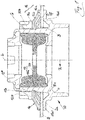
- the body structure 2 which is shown only very fragmentarily, is designed, for example, as usual as a so-called suspension strut dome and has a circular passage opening 3 in which the support bearing for the damper, identified in its entirety with the reference number 10 ("damper” is a synonym for " Vibration damper ”) is arranged.
- Components of the support bearing 10 are, in particular, a support bearing flange 11, a basically conventional support bearing cover 12 * and, here, also a so-called support bearing nut 120 ( Fig. 1 ) or 121 ( Fig.2a ), as well as (as usual) a bearing element 13 for the piston rod made of an elastomer-metal mixed construction, which is arranged or stored here in the support bearing flange 11 and in turn carries the piston rod of the damper in the usual way.
- a spring support is not shown in the figures, by means of which a suspension spring, likewise not shown, is supported in the usual manner in an area F of the support bearing 10.
- the body of the vehicle is partially supported by such a suspension spring on the wheel suspension or on the wheel of the vehicle to which the damper is assigned.
- the support bearing flange 11 which is at least approximately rotationally symmetrical with respect to the longitudinal damper axis L, has an annular base structure 11a, which is approximately horizontal in the installed state in the vehicle, from which a circular cylindrical collar 11b protrudes upwards concentrically to the longitudinal damper axis L in the figure and in the real installed state. With this collar 11b, the support bearing flange 11 penetrates the passage opening 3 in the body structure 2, a ring section 11ar of the basic structure 11a lying outside the collar 11b in the radial direction R with respect to the longitudinal axis L resting on the underside of the body structure 2.
- the circular-cylindrical collar 11b (which describes a hollow cylinder) has an external thread on its outer lateral surface, onto which the support bearing nut 120 or 121, which is or can be designed like a conventional screw nut, is screwed with its internal thread. This internal thread and the named external thread are collectively marked with the letter G.
- this bearing element 13 which functions as a kind of bearing block for the piston rod 1 of the damper 1 in the support bearing flange 11
- this bearing element 13 is, as is usual with damper support bearings, formed by an approximately hollow-cylindrical elastomer element 13a, which has a circular ring-shaped metallic disk 13b engages around in its edge area and thus carries it, the piston rod of the damper being inserted with a threaded rod section through a central passage opening in the disk 13b and fastened to it by means of a screw nut (not shown).
- an auxiliary clamping element 16 is provided between the support bearing nut 120 and the edge ring section 2a of the body structure 2, which acts both as a washer and as a slightly resilient element, and in particular to maintain the required clamping force to secure the support bearing flange 11 on the body structure 2 guaranteed under all circumstances.
- the auxiliary clamping element 16 also protects the body structure 2, which is usually already painted prior to mounting the support bearing 10, from damage or abrasion of the paint layer when the support bearing nut 120 is tightened but to a sufficient extent a spring property in the manner of a plate spring lying between the edge ring section 2a of the body structure 2 and the support bearing nut 120 and thus ensures under all (adverse) circumstances the maintenance of a sufficient tensioning force (or preload) in the by the with the thread G provided collar 11b of the support bearing flange 11 and the screw connection formed by the support bearing nut 120.
- this spring property is essentially achieved by the shape of the auxiliary tensioning element 16.
- This annular flange 16a is followed by a transition section 16b, which merges into what is known as a force transmission section 16c, which is designed in the manner of a hollow cylinder with the longitudinal axis L of the thread G and envelops a section of the collar 11b.
- the support bearing nut 120 rests on the force transmission section 16c or acts on it in a pressing manner when it is tightened.
- the transition section 16b when viewed from the longitudinal axis L of the thread G (and thus quasi viewed from the inside) runs obliquely or inclined with respect to the longitudinal axis L of the thread G and thus forms a conical wall section, so that the force transmission section 16c in the longitudinal axis direction L of the thread G does not rest on the edge ring section 2a of the body structure when viewed, the auxiliary tensioning element 16 can act like a disc spring. This effect is reinforced by the fact that the transition section 16b of the auxiliary tensioning element 16 is inclined relative to the longitudinal axis L of the thread G, even when viewed from the outside.
- support ribs 16d are provided on the transition section 16b of the auxiliary tensioning element 16, distributed over its circumference, via which the spring rate or spring stiffness of the auxiliary tensioning element 16 can be specifically determined in connection with the wall thickness of the transition section 16b.
- these support ribs 16d are provided on the inside of the wall of the transition section 16b, which is a hollow truncated cone.
- Support ribs which, when viewed in a projection onto the longitudinal axis L, quasi coincide with the latter, can also be provided on the outside of the lateral surface of the said truncated cone.
- this auxiliary tensioning element 16 can be that it bridges unevenness in the edge ring section 2a of the body structure 2. Such unevenness can result, for example, from welding points between different body panels which meet in this edge ring section 2a and are welded to one another here.
- the support bearing nut 120 and the support bearing cover 12 * are separate components from one another, but this can also be designed differently, ie in particular the support bearing nut 120 and the support bearing cover 12 * can be a coherent "common” component "Be a component.
- the collar 11b of the support bearing flange 11 is inserted through the passage opening 3 from the vibration damper 1 or its damper piston or from the side of the body structure 2 facing the wheel suspension, so that the support bearing nut 120 sits on the The side of the body structure 2 facing away from the wheel or the actual wheel suspension is located, but this can also be configured the other way round.
- the support bearing cover 12 * which here (also) approximately has the shape of a hollow circular cylindrical ring, on the inner wall of which, as shown in the figure, some recesses that do not have a separate reference number are provided.
- a counter-holder, not shown, can act on these recesses when the support bearing nut 120 is automatically screwed together.
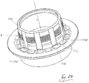
- Fig.2b one recognizes in detail in Fig.2a that some elements are designed similarly to the first exemplary embodiment, but that no auxiliary tensioning element (16) is provided, but that the support bearing nut 121 rests directly on the edge ring section 2a of the body structure 2 here.
- the necessary Preload or tension force in the screw connection formed by the support bearing nut 121 and the collar 11b of the support bearing flange 11 (with said thread G) is ensured by a measure or shaping to increase the elasticity of the collar 11b in the direction of the longitudinal axis L of the thread G.
- This elasticity-increasing shape of the collar 11b is formed by several segments 11c and sectors 11d in the wall of the collar 11b or in a transition area between the basic structure 11a and the collar 11b of the support bearing flange 11, which has a reduced wall thickness compared to an adjacent section of the respective structure have.
- Said segments 11c are provided in the area of the thread G and have - like Fig.2b shows - approximately the shape of a rectangle, the longer edge of which runs parallel to the longitudinal axis L of the thread G.
- the sectors 11d mentioned, however, are located in the transition area from the collar 11b to the basic structure 11a or in an annular section of the basic structure 11a, which is adjoined by the aforementioned annular section 11ar of the basic structure 11a.
- only said segments 11c or said sectors 1d each provided multiple times and preferably evenly distributed over the circumference of the support bearing flange 11, can be provided.
Landscapes
- Engineering & Computer Science (AREA)
- Mechanical Engineering (AREA)
- Springs (AREA)
- Fluid-Damping Devices (AREA)
- Vehicle Body Suspensions (AREA)
Claims (8)
- Palier de support (10) d'un amortisseur de vibrations (1) ou d'une unité à amortisseur à ressort dans la suspension de roue d'un véhicule, le palier de support comprenant une bride (11) qui est supportée par une structure de carrosserie (2) du véhicule, qui est fixée en force et qui s'engage autour d'un élément annulaire (13a) en élastomère dans lequel est suspendu un élément de l'amortisseur (1) et en particulier la tige de piston (la) de celui-ci, et la bride (11) du palier de support pourvue d'un rebord annulaire (11b), qui forme un cylindre creux et dont l'axe de cylindre coïncide au moins approximativement avec l'axe longitudinal (L) de l'amortisseur de vibrations (1), pénétrant dans une ouverture de passage (3) ménagée dans la structure de carrosserie (2) jusqu'à ce qu'un écrou (120) du palier de support ou un couvercle du palier de support, conçu à la manière d'un écrou d'accouplement, puisse être vissé et soit vissé sur un filetage (G) prévu sur la paroi extérieure de ce rebord (11b), lequel écrou ou couvercle du palier de support tire finalement, en s'appuyant sur la structure de carrosserie, la bride (11) du palier de support en direction de la structure de carrosserie (2) de sorte qu'une portion de bord annulaire (2a) de la structure de carrosserie (2), qui entoure l'ouverture de passage (3), soit serrée entre la bride (11) du palier de support et l'écrou (120) du palier de support ou du couvercle du palier de support,
caractérisé en ce qu'une mesure allant au-delà de la conception de l'écrou (120) du palier de support et du filetage (G) est prévue pour augmenter la force de précontrainte dans la liaison par filetage (G) entre l'écrou (120) du palier de support et le rebord (11b), ce pour quoi le rebord (11b) a une conformation augmentant son élasticité en direction de l'axe longitudinal du filetage (G) de sorte que le rebord (11b) de la bride (11) du palier de support soit légèrement déformable élastiquement lorsque l'on regarde dans la direction de l'axe longitudinal (L) dudit filetage (G). - Palier de support selon la revendication 1, caractérisé en ce qu'une mesure allant au-delà de la conception de l'écrou (120) du palier de support et du filetage (G) est prévue entre l'écrou (120) du palier de support et le rebord (11b) pour augmenter la force de précontrainte dans la liaison par filetage (G), ce pour quoi un élément de serrage auxiliaire (16) est serré entre l'écrou (120) du palier de support et la structure de carrosserie.
- Palier de support selon la revendication 1 ou 2, la conformation du rebord augmentant l'élasticité étant formée par une pluralité de secteurs (11d) ou de segments (11c) ayant une épaisseur de paroi réduite par rapport à une portion adjacente.
- Palier de support selon la revendication 3, les segments (11c) étant prévus dans la zone du filetage (G) et ayant approximativement la forme d'un rectangle dont le grand côté est parallèle à l'axe longitudinal du filetage (G).
- Palier de support selon l'une des revendications précédentes, l'élément de serrage auxiliaire (16) possédant une bride annulaire (16a) qui vient en appui sur la structure de carrosserie (2) et une portion de transmission de force (16c) en forme de cylindre creux qui se raccorde directement ou indirectement à ladite bride annulaire, qui s'étend dans la direction de l'axe longitudinal (L) du filetage (G) vers l'écrou (120) du palier de support ou vers le couvercle du palier de support et dont le diamètre est inférieur au diamètre extérieur ou à un diamètre moyen de la bride annulaire (16a).
- Palier de support selon la revendication 5, lorsque l'on regarde depuis l'extérieur, l'élément de serrage auxiliaire (16) comportant une portion de transition linéaire (16b) ou incurvée concave ou convexe, qui est inclinée par rapport à l'axe longitudinal (L) du filetage (G) entre la bride annulaire (16a) et la portion de transmission de force (16c) en forme de cylindre creux qui s'étend, lorsque l'on regarde depuis l'axe longitudinal (L) du filetage (G), également de manière inclinée par rapport à l'axe longitudinal (L) du filetage (G) de sorte que la portion de transmission de force (16c) ne vient pas en appui sur la portion de bord annulaire (2a) de la structure de carrosserie (2), lorsque l'on regarde dans la direction de l'axe longitudinal (L) du filetage (G), de sorte que l'élément de serrage auxiliaire (16) présente une propriété de ressort dans la direction de l'axe longitudinal (L) du filetage (G) à la manière d'un ressort à disque.
- Palier de support selon la revendication 5 ou 6, plusieurs nervures de renforcement (16d) étant prévues au niveau de l'élément de serrage auxiliaire (16) entre la bride annulaire (16a) et la portion de transmission de force (16c) en forme de cylindre creux ou au niveau de la portion de transition (16b).
- Structure de carrosserie (2) comprenant un palier de support selon l'une des revendications précédentes, la bride (11) du palier de support pourvue de son rebord (11b) étant enfichée à travers l'ouverture de passage (3) depuis le côté de la structure de carrosserie (2) qui est dirigé vers l'amortisseur de vibrations (1) ou la suspension de roue.
Applications Claiming Priority (2)
| Application Number | Priority Date | Filing Date | Title |
|---|---|---|---|
| DE102017205091.8A DE102017205091A1 (de) | 2017-03-27 | 2017-03-27 | Stützlager eines Schwingungsdämpfers in der Radaufhängung eines Fahrzeugs |
| PCT/EP2018/054188 WO2018177657A1 (fr) | 2017-03-27 | 2018-02-20 | Palier de support d'un amortisseur de vibrations dans la suspension de roue d'un véhicule |
Publications (2)
| Publication Number | Publication Date |
|---|---|
| EP3600923A1 EP3600923A1 (fr) | 2020-02-05 |
| EP3600923B1 true EP3600923B1 (fr) | 2021-04-21 |
Family
ID=61569221
Family Applications (1)
| Application Number | Title | Priority Date | Filing Date |
|---|---|---|---|
| EP18708928.9A Active EP3600923B1 (fr) | 2017-03-27 | 2018-02-20 | Palier de support d'un amortisseur de vibrations dans la suspension de roue d'un véhicule |
Country Status (5)
| Country | Link |
|---|---|
| US (1) | US11110767B2 (fr) |
| EP (1) | EP3600923B1 (fr) |
| CN (1) | CN110325383B (fr) |
| DE (1) | DE102017205091A1 (fr) |
| WO (1) | WO2018177657A1 (fr) |
Families Citing this family (4)
| Publication number | Priority date | Publication date | Assignee | Title |
|---|---|---|---|---|
| FR3117943B3 (fr) * | 2020-12-18 | 2022-12-23 | Renault Sas | Jambe de force de suspension de vehicule automobile |
| DE102021100226B4 (de) * | 2021-01-08 | 2024-08-08 | Vibracoustic Se | Dämpfer für eine Luftfeder |
| CN116557502A (zh) * | 2023-05-22 | 2023-08-08 | 北方工业大学 | 一种能够承受拉弯重载并防止绳索脱落的偏心滑轮 |
| DE102024120644A1 (de) * | 2024-07-19 | 2026-01-22 | VB-Airsuspension B.V. The Netherlands | Luftfeder-Dämpfereinheit |
Family Cites Families (19)
| Publication number | Priority date | Publication date | Assignee | Title |
|---|---|---|---|---|
| DE384816C (de) | 1919-12-24 | 1923-11-09 | Leopold Ravier | Schraubensicherung |
| FR1163251A (fr) * | 1956-12-11 | 1958-09-24 | Renault | Dispositif élastique |
| DE1780504A1 (de) * | 1968-09-23 | 1972-02-03 | Kronprinz Ag | Zentrierende Fahrzeugradbefestigung fuer einteiige Radscheiben von Fahrzeugraedern |
| US3913649A (en) * | 1974-02-14 | 1975-10-21 | Textron Inc | Fastener assembly |
| FR2620180B1 (fr) * | 1987-09-04 | 1990-01-19 | Aerospatiale | Rondelle ressort en alliage a memoire de forme et son application a un dispositif pour exercer sur une piece une pression evoluant par paliers |
| US5350183A (en) * | 1989-03-21 | 1994-09-27 | Dana Corporation | Steerable axle assembly with preloaded kingpin drawkeys |
| DE4140936A1 (de) | 1991-12-12 | 1993-06-17 | Daimler Benz Ag | Dehnschraube |
| US5678810A (en) * | 1995-10-30 | 1997-10-21 | General Motors Corporation | Pneumatic suspension system |
| DE19719301B4 (de) | 1997-05-07 | 2004-02-12 | Adam Opel Ag | Aufbauseitige Lagerung eines Stoßdämpfers |
| US6382645B1 (en) * | 2000-12-04 | 2002-05-07 | Northstar Manufacturing Co., Inc. | Offset upper strut mount |
| US20040089990A1 (en) * | 2002-06-06 | 2004-05-13 | Labeau George A. | Single point attachment dual path suspension mount |
| JP4188033B2 (ja) * | 2002-08-30 | 2008-11-26 | 本田技研工業株式会社 | 油圧緩衝機の取付構造 |
| DE10312576A1 (de) * | 2003-03-21 | 2004-09-30 | Bayerische Motoren Werke Ag | Federbein-Abstützung für ein nicht gelenktes Fahrzeug-Rad |
| DE102005014325B4 (de) * | 2005-03-24 | 2008-03-13 | Zf Friedrichshafen Ag | Luftfederbein |
| FR2901180A1 (fr) * | 2006-05-16 | 2007-11-23 | Snr Roulements Sa | Dispositif de butee de suspension de vehicule a etancheite renforcee |
| DE102007040734B4 (de) * | 2007-08-29 | 2009-05-07 | Audi Ag | Federbein für eine Radaufhängung von Kraftfahrzeugen |
| DE102008010541B4 (de) | 2008-02-22 | 2012-10-25 | Bayerische Motoren Werke Aktiengesellschaft | Federbein- oder Schwingungsdämpferabstützung für ein Fahrzeugrad |
| DE102012002806A1 (de) | 2011-09-19 | 2013-05-16 | Carl Freudenberg Kg | Federbein und Gehäuse eines Federbeins |
| DE102014218800A1 (de) | 2014-09-18 | 2016-03-24 | Bayerische Motoren Werke Aktiengesellschaft | Dämpferanordnung eines Fahrzeuges |
-
2017
- 2017-03-27 DE DE102017205091.8A patent/DE102017205091A1/de not_active Withdrawn
-
2018
- 2018-02-20 EP EP18708928.9A patent/EP3600923B1/fr active Active
- 2018-02-20 WO PCT/EP2018/054188 patent/WO2018177657A1/fr not_active Ceased
- 2018-02-20 CN CN201880014123.7A patent/CN110325383B/zh active Active
-
2019
- 2019-09-26 US US16/583,461 patent/US11110767B2/en active Active
Non-Patent Citations (1)
| Title |
|---|
| None * |
Also Published As
| Publication number | Publication date |
|---|---|
| DE102017205091A1 (de) | 2018-09-27 |
| US11110767B2 (en) | 2021-09-07 |
| CN110325383A (zh) | 2019-10-11 |
| EP3600923A1 (fr) | 2020-02-05 |
| US20200016949A1 (en) | 2020-01-16 |
| CN110325383B (zh) | 2022-12-13 |
| WO2018177657A1 (fr) | 2018-10-04 |
Similar Documents
| Publication | Publication Date | Title |
|---|---|---|
| DE4011827C2 (fr) | ||
| EP3600923B1 (fr) | Palier de support d'un amortisseur de vibrations dans la suspension de roue d'un véhicule | |
| EP2986485B1 (fr) | Double rondelle ondulée comprenant une couche intermédiaire d'amortissement | |
| EP2532568B1 (fr) | Dispositif de fixation d'un composant, par exemple d'une rambarde, sur une carrosserie de véhicule | |
| DE3125907A1 (de) | Daempfungselement fuer die aufhaengung eines schwingenden koerpers an einer tragkonstruktion | |
| EP3063428B1 (fr) | Palier | |
| DE102014220291A1 (de) | Lagerung für eine Fahrerkabine eines Fahrzeuges | |
| EP3509872B1 (fr) | Roue ferroviaire élastique en plusieurs parties | |
| DE3711692A1 (de) | Stossfaengeranordnung fuer fahrzeuge | |
| EP1718878B1 (fr) | Dispositif de palier pour soutenir un rotor a haute vitesse | |
| DE69519673T2 (de) | Dämpfungsvorrichtung für kraftfahrzeugstabilisatoren und verfahren zu ihrer befestigung | |
| DE102011005405A1 (de) | Befestigungsanordnung | |
| DE3302057A1 (de) | Karosserieseitige elastische lagerung eines federbeins | |
| EP0894203B1 (fr) | Usage d'une bague de fixation à auto-serrage | |
| DE3138534C2 (fr) | ||
| DE102016214179B4 (de) | Stützlager eines Schwingungsdämpfers in der Radaufhängung eines Fahrzeugs | |
| WO2011110457A1 (fr) | Élément de blocage axial de forme annulaire | |
| EP1279842B1 (fr) | Système d'écrou avec rondelle pivotante | |
| EP0023967B1 (fr) | Dispositif de fixation d'un amortisseur de vibrations hydraulique ou analogue dans le tube-support d'une jambe de force à ressort porteuse de roue | |
| EP0457249B1 (fr) | Attelage de remorque mot clef: dispositif antiperte avec distance de sécurité | |
| WO2007110057A1 (fr) | Piston en plusieurs parties pour moteur à combustion interne | |
| EP2860147B1 (fr) | Dispositif de support pour un appareil de travail mobile | |
| DE886983C (de) | Elastische Gelenk- und Tragvorrichtung | |
| EP4124392B1 (fr) | Dispositif tamis permettant de tamiser des matières en vrac | |
| DE29503151U1 (de) | Schwingungstilger |
Legal Events
| Date | Code | Title | Description |
|---|---|---|---|
| STAA | Information on the status of an ep patent application or granted ep patent |
Free format text: STATUS: UNKNOWN |
|
| STAA | Information on the status of an ep patent application or granted ep patent |
Free format text: STATUS: THE INTERNATIONAL PUBLICATION HAS BEEN MADE |
|
| PUAI | Public reference made under article 153(3) epc to a published international application that has entered the european phase |
Free format text: ORIGINAL CODE: 0009012 |
|
| STAA | Information on the status of an ep patent application or granted ep patent |
Free format text: STATUS: REQUEST FOR EXAMINATION WAS MADE |
|
| 17P | Request for examination filed |
Effective date: 20191017 |
|
| AK | Designated contracting states |
Kind code of ref document: A1 Designated state(s): AL AT BE BG CH CY CZ DE DK EE ES FI FR GB GR HR HU IE IS IT LI LT LU LV MC MK MT NL NO PL PT RO RS SE SI SK SM TR |
|
| AX | Request for extension of the european patent |
Extension state: BA ME |
|
| DAV | Request for validation of the european patent (deleted) | ||
| DAX | Request for extension of the european patent (deleted) | ||
| GRAP | Despatch of communication of intention to grant a patent |
Free format text: ORIGINAL CODE: EPIDOSNIGR1 |
|
| STAA | Information on the status of an ep patent application or granted ep patent |
Free format text: STATUS: GRANT OF PATENT IS INTENDED |
|
| INTG | Intention to grant announced |
Effective date: 20201211 |
|
| GRAS | Grant fee paid |
Free format text: ORIGINAL CODE: EPIDOSNIGR3 |
|
| GRAA | (expected) grant |
Free format text: ORIGINAL CODE: 0009210 |
|
| STAA | Information on the status of an ep patent application or granted ep patent |
Free format text: STATUS: THE PATENT HAS BEEN GRANTED |
|
| AK | Designated contracting states |
Kind code of ref document: B1 Designated state(s): AL AT BE BG CH CY CZ DE DK EE ES FI FR GB GR HR HU IE IS IT LI LT LU LV MC MK MT NL NO PL PT RO RS SE SI SK SM TR |
|
| REG | Reference to a national code |
Ref country code: GB Ref legal event code: FG4D Free format text: NOT ENGLISH |
|
| REG | Reference to a national code |
Ref country code: CH Ref legal event code: EP |
|
| REG | Reference to a national code |
Ref country code: DE Ref legal event code: R096 Ref document number: 502018004903 Country of ref document: DE |
|
| REG | Reference to a national code |
Ref country code: IE Ref legal event code: FG4D Free format text: LANGUAGE OF EP DOCUMENT: GERMAN |
|
| REG | Reference to a national code |
Ref country code: AT Ref legal event code: REF Ref document number: 1384269 Country of ref document: AT Kind code of ref document: T Effective date: 20210515 |
|
| REG | Reference to a national code |
Ref country code: LT Ref legal event code: MG9D |
|
| REG | Reference to a national code |
Ref country code: NL Ref legal event code: MP Effective date: 20210421 |
|
| PG25 | Lapsed in a contracting state [announced via postgrant information from national office to epo] |
Ref country code: FI Free format text: LAPSE BECAUSE OF FAILURE TO SUBMIT A TRANSLATION OF THE DESCRIPTION OR TO PAY THE FEE WITHIN THE PRESCRIBED TIME-LIMIT Effective date: 20210421 Ref country code: HR Free format text: LAPSE BECAUSE OF FAILURE TO SUBMIT A TRANSLATION OF THE DESCRIPTION OR TO PAY THE FEE WITHIN THE PRESCRIBED TIME-LIMIT Effective date: 20210421 Ref country code: LT Free format text: LAPSE BECAUSE OF FAILURE TO SUBMIT A TRANSLATION OF THE DESCRIPTION OR TO PAY THE FEE WITHIN THE PRESCRIBED TIME-LIMIT Effective date: 20210421 Ref country code: NL Free format text: LAPSE BECAUSE OF FAILURE TO SUBMIT A TRANSLATION OF THE DESCRIPTION OR TO PAY THE FEE WITHIN THE PRESCRIBED TIME-LIMIT Effective date: 20210421 Ref country code: BG Free format text: LAPSE BECAUSE OF FAILURE TO SUBMIT A TRANSLATION OF THE DESCRIPTION OR TO PAY THE FEE WITHIN THE PRESCRIBED TIME-LIMIT Effective date: 20210721 |
|
| PG25 | Lapsed in a contracting state [announced via postgrant information from national office to epo] |
Ref country code: IS Free format text: LAPSE BECAUSE OF FAILURE TO SUBMIT A TRANSLATION OF THE DESCRIPTION OR TO PAY THE FEE WITHIN THE PRESCRIBED TIME-LIMIT Effective date: 20210821 Ref country code: GR Free format text: LAPSE BECAUSE OF FAILURE TO SUBMIT A TRANSLATION OF THE DESCRIPTION OR TO PAY THE FEE WITHIN THE PRESCRIBED TIME-LIMIT Effective date: 20210722 Ref country code: PL Free format text: LAPSE BECAUSE OF FAILURE TO SUBMIT A TRANSLATION OF THE DESCRIPTION OR TO PAY THE FEE WITHIN THE PRESCRIBED TIME-LIMIT Effective date: 20210421 Ref country code: NO Free format text: LAPSE BECAUSE OF FAILURE TO SUBMIT A TRANSLATION OF THE DESCRIPTION OR TO PAY THE FEE WITHIN THE PRESCRIBED TIME-LIMIT Effective date: 20210721 Ref country code: LV Free format text: LAPSE BECAUSE OF FAILURE TO SUBMIT A TRANSLATION OF THE DESCRIPTION OR TO PAY THE FEE WITHIN THE PRESCRIBED TIME-LIMIT Effective date: 20210421 Ref country code: PT Free format text: LAPSE BECAUSE OF FAILURE TO SUBMIT A TRANSLATION OF THE DESCRIPTION OR TO PAY THE FEE WITHIN THE PRESCRIBED TIME-LIMIT Effective date: 20210823 Ref country code: RS Free format text: LAPSE BECAUSE OF FAILURE TO SUBMIT A TRANSLATION OF THE DESCRIPTION OR TO PAY THE FEE WITHIN THE PRESCRIBED TIME-LIMIT Effective date: 20210421 Ref country code: SE Free format text: LAPSE BECAUSE OF FAILURE TO SUBMIT A TRANSLATION OF THE DESCRIPTION OR TO PAY THE FEE WITHIN THE PRESCRIBED TIME-LIMIT Effective date: 20210421 |
|
| REG | Reference to a national code |
Ref country code: DE Ref legal event code: R097 Ref document number: 502018004903 Country of ref document: DE |
|
| PG25 | Lapsed in a contracting state [announced via postgrant information from national office to epo] |
Ref country code: SK Free format text: LAPSE BECAUSE OF FAILURE TO SUBMIT A TRANSLATION OF THE DESCRIPTION OR TO PAY THE FEE WITHIN THE PRESCRIBED TIME-LIMIT Effective date: 20210421 Ref country code: SM Free format text: LAPSE BECAUSE OF FAILURE TO SUBMIT A TRANSLATION OF THE DESCRIPTION OR TO PAY THE FEE WITHIN THE PRESCRIBED TIME-LIMIT Effective date: 20210421 Ref country code: ES Free format text: LAPSE BECAUSE OF FAILURE TO SUBMIT A TRANSLATION OF THE DESCRIPTION OR TO PAY THE FEE WITHIN THE PRESCRIBED TIME-LIMIT Effective date: 20210421 Ref country code: EE Free format text: LAPSE BECAUSE OF FAILURE TO SUBMIT A TRANSLATION OF THE DESCRIPTION OR TO PAY THE FEE WITHIN THE PRESCRIBED TIME-LIMIT Effective date: 20210421 Ref country code: RO Free format text: LAPSE BECAUSE OF FAILURE TO SUBMIT A TRANSLATION OF THE DESCRIPTION OR TO PAY THE FEE WITHIN THE PRESCRIBED TIME-LIMIT Effective date: 20210421 Ref country code: DK Free format text: LAPSE BECAUSE OF FAILURE TO SUBMIT A TRANSLATION OF THE DESCRIPTION OR TO PAY THE FEE WITHIN THE PRESCRIBED TIME-LIMIT Effective date: 20210421 Ref country code: CZ Free format text: LAPSE BECAUSE OF FAILURE TO SUBMIT A TRANSLATION OF THE DESCRIPTION OR TO PAY THE FEE WITHIN THE PRESCRIBED TIME-LIMIT Effective date: 20210421 |
|
| PLBE | No opposition filed within time limit |
Free format text: ORIGINAL CODE: 0009261 |
|
| STAA | Information on the status of an ep patent application or granted ep patent |
Free format text: STATUS: NO OPPOSITION FILED WITHIN TIME LIMIT |
|
| 26N | No opposition filed |
Effective date: 20220124 |
|
| PG25 | Lapsed in a contracting state [announced via postgrant information from national office to epo] |
Ref country code: IS Free format text: LAPSE BECAUSE OF FAILURE TO SUBMIT A TRANSLATION OF THE DESCRIPTION OR TO PAY THE FEE WITHIN THE PRESCRIBED TIME-LIMIT Effective date: 20210821 Ref country code: AL Free format text: LAPSE BECAUSE OF FAILURE TO SUBMIT A TRANSLATION OF THE DESCRIPTION OR TO PAY THE FEE WITHIN THE PRESCRIBED TIME-LIMIT Effective date: 20210421 |
|
| PG25 | Lapsed in a contracting state [announced via postgrant information from national office to epo] |
Ref country code: IT Free format text: LAPSE BECAUSE OF FAILURE TO SUBMIT A TRANSLATION OF THE DESCRIPTION OR TO PAY THE FEE WITHIN THE PRESCRIBED TIME-LIMIT Effective date: 20210421 |
|
| PG25 | Lapsed in a contracting state [announced via postgrant information from national office to epo] |
Ref country code: MC Free format text: LAPSE BECAUSE OF FAILURE TO SUBMIT A TRANSLATION OF THE DESCRIPTION OR TO PAY THE FEE WITHIN THE PRESCRIBED TIME-LIMIT Effective date: 20210421 |
|
| REG | Reference to a national code |
Ref country code: CH Ref legal event code: PL |
|
| REG | Reference to a national code |
Ref country code: BE Ref legal event code: MM Effective date: 20220228 |
|
| PG25 | Lapsed in a contracting state [announced via postgrant information from national office to epo] |
Ref country code: LU Free format text: LAPSE BECAUSE OF NON-PAYMENT OF DUE FEES Effective date: 20220220 |
|
| PG25 | Lapsed in a contracting state [announced via postgrant information from national office to epo] |
Ref country code: LI Free format text: LAPSE BECAUSE OF NON-PAYMENT OF DUE FEES Effective date: 20220228 Ref country code: IE Free format text: LAPSE BECAUSE OF NON-PAYMENT OF DUE FEES Effective date: 20220220 Ref country code: CH Free format text: LAPSE BECAUSE OF NON-PAYMENT OF DUE FEES Effective date: 20220228 |
|
| PG25 | Lapsed in a contracting state [announced via postgrant information from national office to epo] |
Ref country code: BE Free format text: LAPSE BECAUSE OF NON-PAYMENT OF DUE FEES Effective date: 20220228 |
|
| P01 | Opt-out of the competence of the unified patent court (upc) registered |
Effective date: 20230427 |
|
| REG | Reference to a national code |
Ref country code: AT Ref legal event code: MM01 Ref document number: 1384269 Country of ref document: AT Kind code of ref document: T Effective date: 20230220 |
|
| PG25 | Lapsed in a contracting state [announced via postgrant information from national office to epo] |
Ref country code: AT Free format text: LAPSE BECAUSE OF NON-PAYMENT OF DUE FEES Effective date: 20230220 |
|
| PG25 | Lapsed in a contracting state [announced via postgrant information from national office to epo] |
Ref country code: MK Free format text: LAPSE BECAUSE OF FAILURE TO SUBMIT A TRANSLATION OF THE DESCRIPTION OR TO PAY THE FEE WITHIN THE PRESCRIBED TIME-LIMIT Effective date: 20210421 Ref country code: CY Free format text: LAPSE BECAUSE OF FAILURE TO SUBMIT A TRANSLATION OF THE DESCRIPTION OR TO PAY THE FEE WITHIN THE PRESCRIBED TIME-LIMIT Effective date: 20210421 Ref country code: AT Free format text: LAPSE BECAUSE OF NON-PAYMENT OF DUE FEES Effective date: 20230220 |
|
| PG25 | Lapsed in a contracting state [announced via postgrant information from national office to epo] |
Ref country code: HU Free format text: LAPSE BECAUSE OF FAILURE TO SUBMIT A TRANSLATION OF THE DESCRIPTION OR TO PAY THE FEE WITHIN THE PRESCRIBED TIME-LIMIT; INVALID AB INITIO Effective date: 20180220 |
|
| PG25 | Lapsed in a contracting state [announced via postgrant information from national office to epo] |
Ref country code: MT Free format text: LAPSE BECAUSE OF FAILURE TO SUBMIT A TRANSLATION OF THE DESCRIPTION OR TO PAY THE FEE WITHIN THE PRESCRIBED TIME-LIMIT Effective date: 20210421 |
|
| PG25 | Lapsed in a contracting state [announced via postgrant information from national office to epo] |
Ref country code: TR Free format text: LAPSE BECAUSE OF FAILURE TO SUBMIT A TRANSLATION OF THE DESCRIPTION OR TO PAY THE FEE WITHIN THE PRESCRIBED TIME-LIMIT Effective date: 20210421 |
|
| PGFP | Annual fee paid to national office [announced via postgrant information from national office to epo] |
Ref country code: GB Payment date: 20260219 Year of fee payment: 9 |
|
| PGFP | Annual fee paid to national office [announced via postgrant information from national office to epo] |
Ref country code: DE Payment date: 20260210 Year of fee payment: 9 |
|
| PGFP | Annual fee paid to national office [announced via postgrant information from national office to epo] |
Ref country code: AT Payment date: 20260410 Year of fee payment: 5 |
|
| PGFP | Annual fee paid to national office [announced via postgrant information from national office to epo] |
Ref country code: FR Payment date: 20260219 Year of fee payment: 9 |