EP3601012B1 - Faltrahmen für kinderwägen oder dergleichen - Google Patents
Faltrahmen für kinderwägen oder dergleichen Download PDFInfo
- Publication number
- EP3601012B1 EP3601012B1 EP18716346.4A EP18716346A EP3601012B1 EP 3601012 B1 EP3601012 B1 EP 3601012B1 EP 18716346 A EP18716346 A EP 18716346A EP 3601012 B1 EP3601012 B1 EP 3601012B1
- Authority
- EP
- European Patent Office
- Prior art keywords
- folding frame
- condition
- grip element
- articulation axis
- actuation
- Prior art date
- Legal status (The legal status is an assumption and is not a legal conclusion. Google has not performed a legal analysis and makes no representation as to the accuracy of the status listed.)
- Active
Links
Images





Classifications
-
- B—PERFORMING OPERATIONS; TRANSPORTING
- B62—LAND VEHICLES FOR TRAVELLING OTHERWISE THAN ON RAILS
- B62B—HAND-PROPELLED VEHICLES, e.g. HAND CARTS OR PERAMBULATORS; SLEDGES
- B62B7/00—Carriages for children; Perambulators, e.g. dolls' perambulators
- B62B7/04—Carriages for children; Perambulators, e.g. dolls' perambulators having more than one wheel axis; Steering devices therefor
- B62B7/06—Carriages for children; Perambulators, e.g. dolls' perambulators having more than one wheel axis; Steering devices therefor collapsible or foldable
- B62B7/064—Carriages for children; Perambulators, e.g. dolls' perambulators having more than one wheel axis; Steering devices therefor collapsible or foldable the handle bar being parallel to the front leg
- B62B7/066—Carriages for children; Perambulators, e.g. dolls' perambulators having more than one wheel axis; Steering devices therefor collapsible or foldable the handle bar being parallel to the front leg the handle bar moves in parallel relation during folding
-
- B—PERFORMING OPERATIONS; TRANSPORTING
- B62—LAND VEHICLES FOR TRAVELLING OTHERWISE THAN ON RAILS
- B62B—HAND-PROPELLED VEHICLES, e.g. HAND CARTS OR PERAMBULATORS; SLEDGES
- B62B2205/00—Hand-propelled vehicles or sledges being foldable or dismountable when not in use
- B62B2205/20—Catches; Locking or releasing an articulation
- B62B2205/22—Catches; Locking or releasing an articulation remotely controlled, e.g. from the handlebar
Definitions
- the present invention relates to a folding frame for strollers, baby carriages and the like.
- Folding frames for strollers or baby carriages are known which are essentially constituted by a lower framework, which comprises one or two front posts and one or two rear posts, which support in a downward region respective wheel assemblies, and by at least one upper post, known in the jargon as "handle tube", which ends in an upward region with the grip element or handle of the frame and can move with respect to the lower framework.
- the handle tube or tubes move, with respect to the front posts, with an exclusively translational motion (which is typically parallel to the direction of extension of the front posts), with a combined rotary and translational motion, or with a rotary motion.
- a typical constructive solution provides for the front and rear posts to be mutually hinged about an articulation axis while the handle tube or tubes are kinematically connected by means of at least one connecting linkage and/or translation sleeves to the front post.
- Kinematic interconnection means are interposed between the front posts and the rear posts and are constituted by at least one upper tension member which connects the rear post or posts to the front post or posts, while it is possible to provide furthermore one or more lower guiding tension members which connect the rear posts to the handle tubes.
- the locking of the frame in the open condition is ensured by locking means which act for example between the handle tube and the respective front post in the contact region.
- the release of the locking means is typically performed by the user by acting on actuation means which are arranged on the handle tubes or at the grip element.
- EP 1 232 927 A2 on which the preamble of claim 1 is based, describes an umbrella-type folding frame.
- Other similar folding frames are disclosed in WO 2004/074070 A1 and in WO 2014/097217 A1 .
- the aim of the present invention is to provide a folding frame for strollers, baby carriages and the like that is capable of improving the background art in one or more of the aspects indicated above.
- an object of the invention is to provide a folding frame for strollers, baby carriages and the like that is highly reliable, relatively easy to provide and at competitive costs.
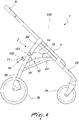
- the folding frame for strollers, baby carriages or the like designated generally by the reference numeral 1, comprises a lower framework 2 which has at least one front post 2a and at least one rear post 2b which are connected in a downward region to respective wheel assemblies 3a, 3b.
- the lower framework 2 is provided with two rear posts 2b, and in the specific case a right rear post and a left rear post, and two front posts 2a, in particular a right front post and a left front post.
- the or each rear post 2b can move on command, with respect to the front post or posts 2a, with a rotary motion about a first articulation axis 101, which is substantially transverse to the direction of longitudinal extension 100 of the folding frame 1 during the transition of the folding frame 1 from an extended or open condition to a collapsed or closed condition and vice versa.
- the or each rear post 2b can move on command with respect to a coupling body 2a' which is integral with the respective front post 2a.
- the lower framework 2 is connected kinematically to at least one handle tube 4, which is associated with or forms at least one upper grip element 5.
- the or each handle tube 4 can move with respect to the respective front post 2a along a movement trajectory which has at least one component that is parallel to the direction of main extension of the front post 2a, in order to move between an active condition (shown for example in Figure 1 ), in which the upper grip element 5 is spaced and arranged upward with respect to the end portion that is uppermost during use of the lower framework 2, and an inactive condition (shown in Figure 11 ), in which the upper grip element 5 is arranged closer to the end portion that is uppermost during use of the lower framework 2.
- an active condition shown for example in Figure 1
- an inactive condition shown in which the upper grip element 5 is spaced and arranged upward with respect to the end portion that is uppermost during use of the lower framework 2
- an inactive condition shown in Figure 11
- the lower framework 2 supports an actuation device 10 which has an actuation grip element 11, which can move on command between a first position and a second position.
- the actuation device 10 is connected kinematically to at least one device 12 for interconnection between at least one rear post 2b and at least one respective front post 2a in order to pass, as a consequence of the transition of the actuation grip element 11 between the first position and the second position, between an extended position, in which the respective front and rear posts (2a, 2b) are kept angularly spaced, and a folded position, in which the respective front and rear posts (2a, 2b) are kept angularly closer.
- the folding frame 1 furthermore comprises at least one first body 21 for locking the interconnection device 12 in the extended position and at least one second locking body 22.
- the first locking body 21 is connected kinematically to the actuation grip element 11.
- the second locking body 22 is adapted to act between a front post 2a and the respective handle tube 4 in order to keep the handle tube 4 locked with respect to the front post 2a in the active position.
- the second locking body 22 is adapted to keep in the active position the handle tube 4 at least when the interconnection device 12 is in the extended position.
- the folding frame 1 comprises at least one element 23 for interconnection between each rear post 2b and the respective handle tube 4, said interconnection element 23 being adapted to cause the movement of the handle tube 4 between the inactive position and the active position and vice versa as a consequence of the transition of the interconnection device 12 between the extended condition and the folded condition and vice versa.
- the actuation grip element 11 is supported by the interconnection device 12.
- the actuation grip element 11 is supported directly by the interconnection device 12.
- the actuation grip element 11 is supported by the interconnection device 12 so that it can rotate about a second articulation axis 102 which is substantially parallel to the first articulation axis 101.
- the interconnection device 12 comprises a toggle device which comprises a first connecting body 13 and a second connecting body 14.
- the first connecting body 13 has a first end 13a which is pivoted, about a third articulation axis 103 which is substantially parallel to the first articulation axis 101, to a respective rear post 2b, and a second end 13b, which is pivoted to the second connecting body 14 about a fourth articulation axis 104 which is substantially parallel to the third articulation axis 103.
- the second connecting body 14 is supported rotatably, about a fifth articulation axis 105 which is substantially parallel to the third and fourth articulation axes 104 and 105, by the respective front post 2a.
- the second connecting body 14 is supported, so that it can rotate about the fifth articulation axis 105, by a coupling body 15 which is integral with a front post 2a.
- the first locking body 21 is adapted to lock the rotation of the first connecting body 13 with respect to the second connecting body 14, thus providing a rigid connection between the respective front posts 2a and rear posts 2b.
- the first locking body 21 comprises a hook 21a which is supported by the second connecting body 14 and is adapted to pass between an uncoupling condition and a coupling condition with respect to a respective abutment 21b which is supported by the first connecting body 13 following the transition of the interconnection device 12 between the folded condition and the extended condition and vice versa.
- first automatic means for the actuation of the hook 21a which comprise for example an elastic loading device 21c, which are adapted to determine the transition of the hook 21a from the uncoupling condition to the coupling condition with the respective abutment 21b when a preset relative angular position is reached between the first connecting body 13 and the second connecting body 14.
- the second locking body 22 comprises at least one locking pin 22a.
- the locking pin 22a is supported appropriately by the coupling body 15 and is adapted to pass between a condition of disengagement with respect to the respective handle tube 4 and a position of engagement with the respective handle tube 4.
- the transition of the locking pin 22a from the disengagement condition to the engagement position is performed during the transition of the folding frame 1 between the closed condition and the open condition.
- the locking pin 22a is supported so that it can slide by the coupling body 15 so that it can move along a sliding direction 201.
- the sliding direction 201 is extended substantially at right angles to the direction of extension of the respective front post 2a.
- the locking pin 22a is partially accommodated slidingly within a first seat that is formed on the respective front post 2a and is provided with an engagement head 22a', which is designed, in the engagement position (shown for example in Figure 1 ), to enter a second seat which is integral with the respective handle tube 4 in order to render the handle tube 4 integral with the respective front post 2a, at least when the interconnection device 12 is moved into the extended condition.
- second automatic means for the actuation of the locking pin 22a which comprise for example an elastic loading device 22c and are designed to act on the locking pin 22a in order to apply such an action as to push the engagement head 22a' toward the second seat.
- the actuation grip element 11 is connected kinematically to the second connecting body 14.
- the actuation grip element 11 is connected kinematically to an elongated pusher body 40.
- the pusher body 40 has a first end 40a which is associated rotatably, in an eccentric manner with respect to the second articulation axis 102, with the actuation grip element 11 and a second end 40b which is associated with, and connected kinematically to, the second locking body 22.
- the engagement element 41 comprises a protrusion which is arranged laterally adjacent to the hook 21a and is designed, when the actuation grip element 11 is moved from the first position toward the second position (which in the views shown in the figures corresponds to a clockwise upward rotation), to act on the hook 21a in contrast with the action of the first elastic loading device 21c in order to disengage the hook 21a from the abutment 21b, so as to consequently allow the relative rotation between the rear post 2b and the first connecting body 13 about the third articulation axis 103 and between the first connecting body 13 and the second connecting body 14 about the fourth articulation axis 104.
- the pusher body 40 is provided with an inclined portion 42 which engages a rocker element 43 so that when the actuation grip element 11 is moved from the first position toward the second position (which in the views shown in the figures corresponds to a clockwise upward rotation), a traction is applied to the locking pin 22 in contrast with the action of the second elastic loading device 22c in order to disengage the engagement head 22a' from the second seat formed on the respective handle tube 4, so as to allow consequently the movement of the or each handle tube 4 with respect to the respective front post 2a and therefore the transition of the handle tubes from the active condition to the inactive position.
- the interconnection device 12 rigidly mutually connects the rear posts 2b to the respective front posts 2a by virtue of the action of the first locking body 21, which prevents relative rotation between the first connecting body 13 and the second connecting body 14.
- the second locking body 22 furthermore acts between the front post 2a and the respective handle tube 4, ensuring that each handle tube is maintained in the active position.
- the pusher body 40 moves along a substantially longitudinal direction toward the respective front post 2a.
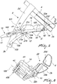
- the engagement element 41 disengages the hook 21a from the abutment 21b ( Figure 5 ), allowing relative rotation between the first connecting body 13 and the second connecting body 14 about the fourth articulation axis, causing the angular approach between the front posts 2a and the rear posts 2b.
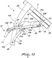
- the advancement toward the front post 2a of the second end 40b of the pusher body 40 furthermore causes the downward rotation of the rocker 42 and the simultaneous disengagement of the engagement head 22a' from the respective handle tube 4 ( Figure 8 ) and therefore the simultaneous transition of the handle tubes toward the inactive position ( Figure 10 and Figure 11 ).
- the weight itself of the wheel assemblies, of the front and rear posts and of the handle tubes facilitates the collapse of the frame, while it is lifted by the actuation grip element 11.
- the folding frame 1 is provided with the interconnection element 23, the movement by gravity of the handle tubes 4 from the active condition to the inactive condition in practice draws the rear posts 2b angularly closer to the respective front posts.
- interconnection element 23 facilitates the angular spacing between the front posts 2a and the rear posts 2b, moving into extension the interconnection device 12.
- the engagement head 22a' presses, as a consequence of the action of the second elastic loading device 22c, toward the handle tube 4 and the first elastic loading device 21c acts on the hook 21c in order to allow its automatic engagement with the abutment 21b once the open condition has been reached.
- the interconnection device 12 also forms one or more coupling seats with a receptacle for accommodating a child, typically a stroller, a baby carriage or a car seat.
- the weight applied by the receptacle coupled to the interconnection device furthermore produces a force that tends to move mutually apart the front posts 2a and the rear posts 2b, consequently ensuring the correct engagement of the hook 21a with the abutment 21b and of the engagement head 22a' with the second seat provided in the handle tube 4.
- the invention achieves the proposed aim and objects, providing a folding frame for stroller, baby carriages or the like that passes easily from the open condition to the closed condition and vice versa.
- the materials used may be any according to the requirements and the state of the art.
Landscapes
- Engineering & Computer Science (AREA)
- Chemical & Material Sciences (AREA)
- Combustion & Propulsion (AREA)
- Transportation (AREA)
- Mechanical Engineering (AREA)
- Carriages For Children, Sleds, And Other Hand-Operated Vehicles (AREA)
Claims (13)
- Ein Faltrahmen (1) für Kinderwägen oder dergleichen, der einen unteren Rahmen (2) umfasst, ausgestattet mit mindestens einem vorderen Ständer (2a) und mindestens einem hinteren Ständer (2b), die in einem unteren Bereich mit entsprechenden Radaufbauten (3a, 3b) verbunden sind, wobei der mindestens eine hintere Ständer (2b) auf Befehl mit Bezug auf den mindestens einen vorderen Ständer (2a) mit einer Drehbewegung um eine erste Gelenkachse (101) beweglich ist, die im Wesentlichen quer zur Richtung der Längsausrichtung (100) des Faltrahmens (1) während des Übergangs des Faltrahmens (1) aus einem ausgeklappten offenen Zustand in einen zusammengeklappten geschlossenen Zustand und umgekehrt ist, wobei der untere Rahmen (2) kinematisch mit mindestens einem Schiebegriffrohr (4) verbunden ist, das mindestens ein oberes Griffelement (5) bildet und sich mit Bezug auf den mindestens einen vorderen Ständer (2a) entlang einer Bewegungstrajektorie bewegen kann, die mindestens eine Komponente hat, welche parallel zur Richtung der Hauptausdehnung des mindestens einen vorderen Ständers (2a) ist, um sich zwischen einem aktiven Zustand, in welchem das Griffelement (5) mit Bezug auf den Endabschnitt des unteren Rahmens (2) der während des Gebrauchs am höchsten liegt beabstandet und oberhalb desselben angeordnet ist und einem inaktiven Zustand zu bewegen, in welchem das Griffelement (5) angeordnet ist, um nahe dem Endabschnitt des unteren Rahmens (2) zu sein, der während des Gebrauchs am höchsten ist, wobei der untere Rahmen (2) eine Betätigungsvorrichtung (10) trägt, die mit einem Betätigungsgriffelement (11) ausgestattet ist, der sich auf Befehl zwischen einer ersten Position und einer zweiten Position bewegen kann, wobei die Betätigungsvorrichtung (10) kinematisch mit mindestens einer Zwischenschaltungsvorrichtung (12) für die Verbindung zwischen den mindestens einen hinteren Ständer (2b) und mindestens einem entsprechenden vorderen Ständer (2a) verbunden ist, um in Folge des Übergangs des Betätigungsgriffelements (11) zwischen der ersten Position und der zweiten Position zwischen einem ausgeklappten Zustand, in welchem der jeweilige vordere und hintere Ständer (2a, 2b) winklig beabstandet gehalten sind und einem zusammengeklappten Zustand zu wechseln, in welchem der entsprechende vordere und hintere Ständer (2a, 2b) winklig nahe beieinandergehalten sind, wobei es mindestens einen ersten Blockierkörper (21) gibt, der kinematisch mit dem Betätigungsgriffelement (11) verbunden ist, um die Zwischenschaltungsvorrichtung (12) in der ausgeklappten Position zu blockieren und mindestens einen zweiten Blockierkörper (22) der zwischen dem mindestens einen vorderen Ständer (2a) und dem entsprechenden Schiebegriffrohr (4) wirkt, um das Schiebegriffrohr (4) in der aktiven Position blockiert zu halten, dadurch gekennzeichnet, dass die Zwischenschaltungsvorrichtung (12) eine Kippvorrichtung umfasst, die einen ersten Verbindungskörper (13) und einen zweiten Verbindungskörper (14) umfasst, wobei der erste Verbindungskörper (13) ein erstes Ende (13a) hat, dass um eine dritte Gelenkachse (103), die im Wesentlichen parallel zu der ersten Gelenkachse (101) ist drehgelenkig mit einem entsprechenden hinteren Ständer (2b) verbunden ist und ein zweites Ende (13b), das um eine vierte Gelenkachse (104), die im Wesentlichen parallel zu der dritten Gelenkachse (103) ist, drehgelenkig mit dem zweiten Verbindungskörper (14) verbunden ist, wobei der zweite Verbindungskörper (14) von dem entsprechenden vorderen Ständer (2a) so gelagert ist, dass er sich um eine fünfte Gelenkachse (105) drehen kann, welche im Wesentlichen parallel zu der dritten und der vierten Gelenkachse (103, 104) ist.
- Der Faltrahmen (1) gemäß Anspruch 1, dadurch gekennzeichnet, dass das Betätigungsgriffelement (11) von der Zwischenschaltungsvorrichtung (12) getragen ist.
- Der Faltrahmen (1) gemäß Anspruch 2, dadurch gekennzeichnet, dass das Betätigungsgriffelement (11) von der Zwischenschaltungsvorrichtung (12) so getragen ist, dass es sich um eine zweite Gelenkachse (102) drehen kann, die im Wesentlichen parallel zu der ersten Gelenkachse (101) ist.
- Der Faltrahmen (1) gemäß einem oder mehreren der obigen Ansprüche, dadurch gekennzeichnet, dass der zweite Blockierkörper (22) kinematisch mit dem Betätigungsgriffelement (11) verbunden ist.
- Der Faltrahmen (1) gemäß einem oder mehreren der obigen Ansprüche, dadurch gekennzeichnet, dass er mindestens ein Element (23) zur Verbindung zwischen dem mindestens einen hinteren Ständer (2b) und dem mindestens einen Schiebegriffrohr (4) umfasst, welches ausgebildet ist, um die Bewegung des Schiebegriffrohrs (4) zwischen der inaktiven Position und der aktiven Position und umgekehrt in Folge des Übergangs der Zwischenschaltungsvorrichtung (12) zwischen dem ausgeklappten Zustand und dem zusammengeklappten Zustand und umgekehrt zu bestimmen.
- Der Faltrahmen (1) gemäß Anspruch 3, dadurch gekennzeichnet, dass das Betätigungsgriffelement (11) von dem unteren Rahmen (2) so getragen ist, dass es sich um die zweite Gelenkachse (102) drehen kann, die im Wesentlichen parallel zu der ersten Gelenkachse (101) ist.
- Der Faltrahmen (1) gemäß einem oder mehreren der obigen Ansprüche, dadurch gekennzeichnet, dass der zweite Verbindungskörper (14) von einem Kopplungskörper (15), welcher integral mit einem vorderen Ständer (2a) ist, so getragen ist, dass er sich um die fünfte Gelenkachse (105) drehen kann.
- Der Faltrahmen (1) gemäß Anspruch 7, dadurch gekennzeichnet, dass der zweite Blockierkörper (22) mindestens einen Sperrstift (22a) umfasst, der von dem Kopplungskörper (15) getragen und ausgebildet ist, um zwischen einem Zustand des Nichteingreifens mit dem entsprechenden Schiebegriffrohr (4) und einem Position des Eingreifens mit dem entsprechenden Schiebegriffrohr (4) in Folge der Bewegung des Faltrahmens (1) aus dem geschlossenen Zustand in den offenen Zustand zu wechseln.
- Der Faltrahmen (1) gemäß Anspruch 8, dadurch gekennzeichnet, dass der erste Blockierkörper (21) einen Haken (21a) umfasst, der von dem zweiten Verbindungskörper (14) getragen und ausgebildet ist, um zwischen einem Endkopplungszustand und einem Kopplungszustand mit einem entsprechenden Widerlager (21b) dass von dem ersten Verbindungskörper (13) getragen ist, in Folge des Übergangs der Zwischenschaltungsvorrichtung (12) zwischen dem zusammengeklappten Zustand und dem ausgeklappten Zustand und umgekehrt zu wechseln.
- Der Faltrahmen (1) gemäß Anspruch 9, dadurch gekennzeichnet, dass das Betätigungsgriffelement (11) kinematisch mit dem ersten Blockierkörper (21) und mit dem zweiten Blockierkörper (22) verbunden ist.
- Der Faltrahmen (1) gemäß Anspruch 10, dadurch gekennzeichnet, dass das Betätigungsgriffelement (11) kinematisch mit einem Schieberkörper (40) verbunden ist, der eine langgestreckte Ausdehnung und ein erstes Ende (40a) hat, welches drehbar, exzentrisch mit Bezug auf die zweite Gelenkachse (102), mit dem Betätigungsgriffelement (11) verbunden ist und ein zweites Ende (40b) das kinematisch mit dem zweiten Blockierkörper (22) verbunden ist, wobei sich entlang der Ausdehnung des Schieberkörpers (40) ein Eingriffselement (41) für den Eingriff für den ersten Blockierkörper (21) befindet.
- Der Faltrahmen (1) gemäß Anspruch 11, dadurch gekennzeichnet, dass das Eingriffselement (41) einen Vorsprung umfasst, der seitlich angrenzend an den entsprechenden Haken (21a) angeordnet ist und konstruiert ist, um wenn das Betätigungsgriffelement (11) aus der ersten Position in die zweite Position bewegt wird, im Kontrast zur Wirkung einer ersten elastischen Spannvorrichtung (21) auf den Haken (21a) einzuwirken, um den Haken (21a) von dem entsprechenden Widerlager (21b) zu lösen, um entsprechend die Relativrotation zwischen dem hinteren Ständer (2b) und dem entsprechenden ersten Verbindungskörper (13) um die dritte Gelenkachse (103) und zwischen dem ersten Verbindungskörper (13) und dem entsprechenden zweiten Verbindungskörper (14) um die vierte Gelenkachse (104) zu ermöglichen.
- Der Faltrahmen (1) gemäß Anspruch 12, dadurch gekennzeichnet, dass der Schieberkörper (40) im Wesentlichen an dem zweiten Ende (40b) einen schrägen Abschnitt (42) hat, der in Eingriff mit einem Schwingenelement (43) steht, so dass wenn das Betätigungsgriffelement (11) aus der ersten Position in die zweiten Position bewegt wird, Zug auf dem Sperrstift (22a) im Kontrast zur Wirkung einer zweiten elastischen Spannvorrichtung (22c) ausgeübt wird, um einen Eingriffskopf (22a') des Sperrstifts (22a) aus einem zweiten Sitz zu lösen, der an dem entsprechenden Schiebegriffrohr (4) geformt ist, um entsprechend den Übergang der Schiebegriffrohre (4) von dem aktiven Zustand in die inaktive Position zu ermöglichen.
Applications Claiming Priority (2)
| Application Number | Priority Date | Filing Date | Title |
|---|---|---|---|
| IT102017000030151A IT201700030151A1 (it) | 2017-03-20 | 2017-03-20 | Telaio ripiegabile per passeggini, carrozzine o simili. |
| PCT/IB2018/051824 WO2018172912A1 (en) | 2017-03-20 | 2018-03-19 | Folding frame for strollers, baby carriages or the like |
Publications (2)
| Publication Number | Publication Date |
|---|---|
| EP3601012A1 EP3601012A1 (de) | 2020-02-05 |
| EP3601012B1 true EP3601012B1 (de) | 2022-08-10 |
Family
ID=59746282
Family Applications (1)
| Application Number | Title | Priority Date | Filing Date |
|---|---|---|---|
| EP18716346.4A Active EP3601012B1 (de) | 2017-03-20 | 2018-03-19 | Faltrahmen für kinderwägen oder dergleichen |
Country Status (4)
| Country | Link |
|---|---|
| EP (1) | EP3601012B1 (de) |
| ES (1) | ES2926705T3 (de) |
| IT (1) | IT201700030151A1 (de) |
| WO (1) | WO2018172912A1 (de) |
Families Citing this family (1)
| Publication number | Priority date | Publication date | Assignee | Title |
|---|---|---|---|---|
| EP3957545B1 (de) | 2020-08-20 | 2023-05-03 | L'Inglesina Baby S.p.A. | Klapprahmen für kinderwagen, babytragen oder dergleichen |
Family Cites Families (4)
| Publication number | Priority date | Publication date | Assignee | Title |
|---|---|---|---|---|
| ITVR20010022A1 (it) * | 2001-02-20 | 2002-08-20 | Inglesina Baby Spa L | Telaio ripiegabile ad ombrello particolarmente per passeggini |
| ITVR20030007U1 (it) * | 2003-02-21 | 2004-08-22 | Inglesina Baby Spa | Telaio a chiusura telescopica particolarmente per passeggini o simili. |
| ITMI20122207A1 (it) * | 2012-12-20 | 2014-06-21 | Peg Perego Spa | Telaio ripiegabile a ombrello per passeggini per bambini o simili |
| ITUB20152212A1 (it) * | 2015-07-15 | 2017-01-15 | Linglesina Baby S P A | Telaio ripiegabile per passeggini, carrozzine e simili. |
-
2017
- 2017-03-20 IT IT102017000030151A patent/IT201700030151A1/it unknown
-
2018
- 2018-03-19 ES ES18716346T patent/ES2926705T3/es active Active
- 2018-03-19 WO PCT/IB2018/051824 patent/WO2018172912A1/en not_active Ceased
- 2018-03-19 EP EP18716346.4A patent/EP3601012B1/de active Active
Also Published As
| Publication number | Publication date |
|---|---|
| ES2926705T3 (es) | 2022-10-27 |
| WO2018172912A1 (en) | 2018-09-27 |
| EP3601012A1 (de) | 2020-02-05 |
| IT201700030151A1 (it) | 2018-09-20 |
Similar Documents
| Publication | Publication Date | Title |
|---|---|---|
| JP5301342B2 (ja) | 折畳式手押し車 | |
| CN105172868B (zh) | 儿童车架和儿童车 | |
| TWI584985B (zh) | 可折疊式嬰兒車 | |
| EP2794383B1 (de) | Faltbarer rahmen für kinderwagen, babytragen und dergleichen | |
| KR101809357B1 (ko) | 접이식 유아용 세발자전거 및 그 접이 방법 | |
| WO2018014526A1 (zh) | 折叠车架 | |
| CN106394643B (zh) | 折叠式的婴儿车 | |
| KR20110114571A (ko) | 개선된 접이식 유모차 | |
| EP3564106A1 (de) | Robotrike | |
| JP2012183848A (ja) | 折畳式乳母車 | |
| CN205327136U (zh) | 一种伸缩折叠婴儿手推车 | |
| CN104908794B (zh) | 儿童车架 | |
| CN103330423A (zh) | 一种儿童娱乐床 | |
| EP1960248B1 (de) | Greifvorrichtung, insbesondere für sportwagen, kinderwagen und dergleichen | |
| CN109515508A (zh) | 婴幼儿推车 | |
| CN106660598B (zh) | 自行车手推车 | |
| CN117246396A (zh) | 一种儿童载具 | |
| CN205854247U (zh) | 婴幼儿车架 | |
| JP6027367B2 (ja) | 折り畳み式手押し車 | |
| WO2018172912A1 (en) | Folding frame for strollers, baby carriages or the like | |
| CN102448792A (zh) | 手推童车或手推车 | |
| GB2540257A (en) | Folding mechanism for car-seat adaptor and stroller having the same | |
| CN101774396A (zh) | 推把可换向的婴儿推车 | |
| WO2014097217A1 (en) | Umbrella-like foldable frame for baby strollers and the like | |
| CN220130196U (zh) | 提篮及儿童载具 |
Legal Events
| Date | Code | Title | Description |
|---|---|---|---|
| STAA | Information on the status of an ep patent application or granted ep patent |
Free format text: STATUS: UNKNOWN |
|
| STAA | Information on the status of an ep patent application or granted ep patent |
Free format text: STATUS: THE INTERNATIONAL PUBLICATION HAS BEEN MADE |
|
| PUAI | Public reference made under article 153(3) epc to a published international application that has entered the european phase |
Free format text: ORIGINAL CODE: 0009012 |
|
| STAA | Information on the status of an ep patent application or granted ep patent |
Free format text: STATUS: REQUEST FOR EXAMINATION WAS MADE |
|
| 17P | Request for examination filed |
Effective date: 20191009 |
|
| AK | Designated contracting states |
Kind code of ref document: A1 Designated state(s): AL AT BE BG CH CY CZ DE DK EE ES FI FR GB GR HR HU IE IS IT LI LT LU LV MC MK MT NL NO PL PT RO RS SE SI SK SM TR |
|
| AX | Request for extension of the european patent |
Extension state: BA ME |
|
| DAV | Request for validation of the european patent (deleted) | ||
| DAX | Request for extension of the european patent (deleted) | ||
| GRAP | Despatch of communication of intention to grant a patent |
Free format text: ORIGINAL CODE: EPIDOSNIGR1 |
|
| STAA | Information on the status of an ep patent application or granted ep patent |
Free format text: STATUS: GRANT OF PATENT IS INTENDED |
|
| INTG | Intention to grant announced |
Effective date: 20220310 |
|
| GRAS | Grant fee paid |
Free format text: ORIGINAL CODE: EPIDOSNIGR3 |
|
| GRAA | (expected) grant |
Free format text: ORIGINAL CODE: 0009210 |
|
| STAA | Information on the status of an ep patent application or granted ep patent |
Free format text: STATUS: THE PATENT HAS BEEN GRANTED |
|
| AK | Designated contracting states |
Kind code of ref document: B1 Designated state(s): AL AT BE BG CH CY CZ DE DK EE ES FI FR GB GR HR HU IE IS IT LI LT LU LV MC MK MT NL NO PL PT RO RS SE SI SK SM TR |
|
| REG | Reference to a national code |
Ref country code: AT Ref legal event code: REF Ref document number: 1510339 Country of ref document: AT Kind code of ref document: T Effective date: 20220815 Ref country code: CH Ref legal event code: EP |
|
| REG | Reference to a national code |
Ref country code: IE Ref legal event code: FG4D |
|
| REG | Reference to a national code |
Ref country code: DE Ref legal event code: R096 Ref document number: 602018039064 Country of ref document: DE |
|
| REG | Reference to a national code |
Ref country code: ES Ref legal event code: FG2A Ref document number: 2926705 Country of ref document: ES Kind code of ref document: T3 Effective date: 20221027 |
|
| REG | Reference to a national code |
Ref country code: NL Ref legal event code: MP Effective date: 20220810 |
|
| REG | Reference to a national code |
Ref country code: LT Ref legal event code: MG9D |
|
| PG25 | Lapsed in a contracting state [announced via postgrant information from national office to epo] |
Ref country code: SE Free format text: LAPSE BECAUSE OF FAILURE TO SUBMIT A TRANSLATION OF THE DESCRIPTION OR TO PAY THE FEE WITHIN THE PRESCRIBED TIME-LIMIT Effective date: 20220810 Ref country code: RS Free format text: LAPSE BECAUSE OF FAILURE TO SUBMIT A TRANSLATION OF THE DESCRIPTION OR TO PAY THE FEE WITHIN THE PRESCRIBED TIME-LIMIT Effective date: 20220810 Ref country code: PT Free format text: LAPSE BECAUSE OF FAILURE TO SUBMIT A TRANSLATION OF THE DESCRIPTION OR TO PAY THE FEE WITHIN THE PRESCRIBED TIME-LIMIT Effective date: 20221212 Ref country code: NO Free format text: LAPSE BECAUSE OF FAILURE TO SUBMIT A TRANSLATION OF THE DESCRIPTION OR TO PAY THE FEE WITHIN THE PRESCRIBED TIME-LIMIT Effective date: 20221110 Ref country code: NL Free format text: LAPSE BECAUSE OF FAILURE TO SUBMIT A TRANSLATION OF THE DESCRIPTION OR TO PAY THE FEE WITHIN THE PRESCRIBED TIME-LIMIT Effective date: 20220810 Ref country code: LV Free format text: LAPSE BECAUSE OF FAILURE TO SUBMIT A TRANSLATION OF THE DESCRIPTION OR TO PAY THE FEE WITHIN THE PRESCRIBED TIME-LIMIT Effective date: 20220810 Ref country code: LT Free format text: LAPSE BECAUSE OF FAILURE TO SUBMIT A TRANSLATION OF THE DESCRIPTION OR TO PAY THE FEE WITHIN THE PRESCRIBED TIME-LIMIT Effective date: 20220810 Ref country code: FI Free format text: LAPSE BECAUSE OF FAILURE TO SUBMIT A TRANSLATION OF THE DESCRIPTION OR TO PAY THE FEE WITHIN THE PRESCRIBED TIME-LIMIT Effective date: 20220810 |
|
| REG | Reference to a national code |
Ref country code: AT Ref legal event code: MK05 Ref document number: 1510339 Country of ref document: AT Kind code of ref document: T Effective date: 20220810 |
|
| PG25 | Lapsed in a contracting state [announced via postgrant information from national office to epo] |
Ref country code: PL Free format text: LAPSE BECAUSE OF FAILURE TO SUBMIT A TRANSLATION OF THE DESCRIPTION OR TO PAY THE FEE WITHIN THE PRESCRIBED TIME-LIMIT Effective date: 20220810 Ref country code: IS Free format text: LAPSE BECAUSE OF FAILURE TO SUBMIT A TRANSLATION OF THE DESCRIPTION OR TO PAY THE FEE WITHIN THE PRESCRIBED TIME-LIMIT Effective date: 20221210 Ref country code: HR Free format text: LAPSE BECAUSE OF FAILURE TO SUBMIT A TRANSLATION OF THE DESCRIPTION OR TO PAY THE FEE WITHIN THE PRESCRIBED TIME-LIMIT Effective date: 20220810 Ref country code: GR Free format text: LAPSE BECAUSE OF FAILURE TO SUBMIT A TRANSLATION OF THE DESCRIPTION OR TO PAY THE FEE WITHIN THE PRESCRIBED TIME-LIMIT Effective date: 20221111 |
|
| PG25 | Lapsed in a contracting state [announced via postgrant information from national office to epo] |
Ref country code: SM Free format text: LAPSE BECAUSE OF FAILURE TO SUBMIT A TRANSLATION OF THE DESCRIPTION OR TO PAY THE FEE WITHIN THE PRESCRIBED TIME-LIMIT Effective date: 20220810 Ref country code: RO Free format text: LAPSE BECAUSE OF FAILURE TO SUBMIT A TRANSLATION OF THE DESCRIPTION OR TO PAY THE FEE WITHIN THE PRESCRIBED TIME-LIMIT Effective date: 20220810 Ref country code: DK Free format text: LAPSE BECAUSE OF FAILURE TO SUBMIT A TRANSLATION OF THE DESCRIPTION OR TO PAY THE FEE WITHIN THE PRESCRIBED TIME-LIMIT Effective date: 20220810 Ref country code: CZ Free format text: LAPSE BECAUSE OF FAILURE TO SUBMIT A TRANSLATION OF THE DESCRIPTION OR TO PAY THE FEE WITHIN THE PRESCRIBED TIME-LIMIT Effective date: 20220810 Ref country code: AT Free format text: LAPSE BECAUSE OF FAILURE TO SUBMIT A TRANSLATION OF THE DESCRIPTION OR TO PAY THE FEE WITHIN THE PRESCRIBED TIME-LIMIT Effective date: 20220810 |
|
| REG | Reference to a national code |
Ref country code: DE Ref legal event code: R097 Ref document number: 602018039064 Country of ref document: DE |
|
| PG25 | Lapsed in a contracting state [announced via postgrant information from national office to epo] |
Ref country code: SK Free format text: LAPSE BECAUSE OF FAILURE TO SUBMIT A TRANSLATION OF THE DESCRIPTION OR TO PAY THE FEE WITHIN THE PRESCRIBED TIME-LIMIT Effective date: 20220810 Ref country code: EE Free format text: LAPSE BECAUSE OF FAILURE TO SUBMIT A TRANSLATION OF THE DESCRIPTION OR TO PAY THE FEE WITHIN THE PRESCRIBED TIME-LIMIT Effective date: 20220810 |
|
| PLBE | No opposition filed within time limit |
Free format text: ORIGINAL CODE: 0009261 |
|
| STAA | Information on the status of an ep patent application or granted ep patent |
Free format text: STATUS: NO OPPOSITION FILED WITHIN TIME LIMIT |
|
| PG25 | Lapsed in a contracting state [announced via postgrant information from national office to epo] |
Ref country code: AL Free format text: LAPSE BECAUSE OF FAILURE TO SUBMIT A TRANSLATION OF THE DESCRIPTION OR TO PAY THE FEE WITHIN THE PRESCRIBED TIME-LIMIT Effective date: 20220810 |
|
| P01 | Opt-out of the competence of the unified patent court (upc) registered |
Effective date: 20230527 |
|
| 26N | No opposition filed |
Effective date: 20230511 |
|
| PG25 | Lapsed in a contracting state [announced via postgrant information from national office to epo] |
Ref country code: SI Free format text: LAPSE BECAUSE OF FAILURE TO SUBMIT A TRANSLATION OF THE DESCRIPTION OR TO PAY THE FEE WITHIN THE PRESCRIBED TIME-LIMIT Effective date: 20220810 |
|
| PG25 | Lapsed in a contracting state [announced via postgrant information from national office to epo] |
Ref country code: MC Free format text: LAPSE BECAUSE OF FAILURE TO SUBMIT A TRANSLATION OF THE DESCRIPTION OR TO PAY THE FEE WITHIN THE PRESCRIBED TIME-LIMIT Effective date: 20220810 |
|
| REG | Reference to a national code |
Ref country code: CH Ref legal event code: PL |
|
| REG | Reference to a national code |
Ref country code: BE Ref legal event code: MM Effective date: 20230331 |
|
| PG25 | Lapsed in a contracting state [announced via postgrant information from national office to epo] |
Ref country code: LU Free format text: LAPSE BECAUSE OF NON-PAYMENT OF DUE FEES Effective date: 20230319 |
|
| REG | Reference to a national code |
Ref country code: IE Ref legal event code: MM4A |
|
| PG25 | Lapsed in a contracting state [announced via postgrant information from national office to epo] |
Ref country code: LI Free format text: LAPSE BECAUSE OF NON-PAYMENT OF DUE FEES Effective date: 20230331 Ref country code: IE Free format text: LAPSE BECAUSE OF NON-PAYMENT OF DUE FEES Effective date: 20230319 Ref country code: CH Free format text: LAPSE BECAUSE OF NON-PAYMENT OF DUE FEES Effective date: 20230331 |
|
| PG25 | Lapsed in a contracting state [announced via postgrant information from national office to epo] |
Ref country code: BE Free format text: LAPSE BECAUSE OF NON-PAYMENT OF DUE FEES Effective date: 20230331 |
|
| PG25 | Lapsed in a contracting state [announced via postgrant information from national office to epo] |
Ref country code: IT Free format text: LAPSE BECAUSE OF FAILURE TO SUBMIT A TRANSLATION OF THE DESCRIPTION OR TO PAY THE FEE WITHIN THE PRESCRIBED TIME-LIMIT Effective date: 20220810 |
|
| PG25 | Lapsed in a contracting state [announced via postgrant information from national office to epo] |
Ref country code: BG Free format text: LAPSE BECAUSE OF FAILURE TO SUBMIT A TRANSLATION OF THE DESCRIPTION OR TO PAY THE FEE WITHIN THE PRESCRIBED TIME-LIMIT Effective date: 20220810 |
|
| PG25 | Lapsed in a contracting state [announced via postgrant information from national office to epo] |
Ref country code: BG Free format text: LAPSE BECAUSE OF FAILURE TO SUBMIT A TRANSLATION OF THE DESCRIPTION OR TO PAY THE FEE WITHIN THE PRESCRIBED TIME-LIMIT Effective date: 20220810 |
|
| PGFP | Annual fee paid to national office [announced via postgrant information from national office to epo] |
Ref country code: ES Payment date: 20250404 Year of fee payment: 8 |
|
| PG25 | Lapsed in a contracting state [announced via postgrant information from national office to epo] |
Ref country code: CY Free format text: LAPSE BECAUSE OF FAILURE TO SUBMIT A TRANSLATION OF THE DESCRIPTION OR TO PAY THE FEE WITHIN THE PRESCRIBED TIME-LIMIT; INVALID AB INITIO Effective date: 20180319 |
|
| PG25 | Lapsed in a contracting state [announced via postgrant information from national office to epo] |
Ref country code: HU Free format text: LAPSE BECAUSE OF FAILURE TO SUBMIT A TRANSLATION OF THE DESCRIPTION OR TO PAY THE FEE WITHIN THE PRESCRIBED TIME-LIMIT; INVALID AB INITIO Effective date: 20180319 |
|
| PG25 | Lapsed in a contracting state [announced via postgrant information from national office to epo] |
Ref country code: TR Free format text: LAPSE BECAUSE OF FAILURE TO SUBMIT A TRANSLATION OF THE DESCRIPTION OR TO PAY THE FEE WITHIN THE PRESCRIBED TIME-LIMIT Effective date: 20220810 |
|
| PGFP | Annual fee paid to national office [announced via postgrant information from national office to epo] |
Ref country code: GB Payment date: 20260317 Year of fee payment: 9 |
|
| PGFP | Annual fee paid to national office [announced via postgrant information from national office to epo] |
Ref country code: DE Payment date: 20260313 Year of fee payment: 9 |
|
| PGFP | Annual fee paid to national office [announced via postgrant information from national office to epo] |
Ref country code: FR Payment date: 20260311 Year of fee payment: 9 |