EP3601015B1 - Elektrischer mehrzwecktractor - Google Patents
Elektrischer mehrzwecktractor Download PDFInfo
- Publication number
- EP3601015B1 EP3601015B1 EP18712674.3A EP18712674A EP3601015B1 EP 3601015 B1 EP3601015 B1 EP 3601015B1 EP 18712674 A EP18712674 A EP 18712674A EP 3601015 B1 EP3601015 B1 EP 3601015B1
- Authority
- EP
- European Patent Office
- Prior art keywords
- tractor
- wheels
- work area
- work
- zone
- Prior art date
- Legal status (The legal status is an assumption and is not a legal conclusion. Google has not performed a legal analysis and makes no representation as to the accuracy of the status listed.)
- Active
Links
Images



Classifications
-
- B—PERFORMING OPERATIONS; TRANSPORTING
- B62—LAND VEHICLES FOR TRAVELLING OTHERWISE THAN ON RAILS
- B62D—MOTOR VEHICLES; TRAILERS
- B62D21/00—Understructures, i.e. chassis frame on which a vehicle body may be mounted
- B62D21/18—Understructures, i.e. chassis frame on which a vehicle body may be mounted characterised by the vehicle type and not provided for in groups B62D21/02 - B62D21/17
- B62D21/186—Understructures, i.e. chassis frame on which a vehicle body may be mounted characterised by the vehicle type and not provided for in groups B62D21/02 - B62D21/17 for building site vehicles or multi-purpose tractors
-
- B—PERFORMING OPERATIONS; TRANSPORTING
- B62—LAND VEHICLES FOR TRAVELLING OTHERWISE THAN ON RAILS
- B62D—MOTOR VEHICLES; TRAILERS
- B62D49/00—Tractors
- B62D49/06—Tractors adapted for multi-purpose use
Definitions
- the present invention relates to a multitasking tractor comprising a base structure, wheels and/or tracks, at least one engine and tools.
- Multitasking tractors are now well known and used in various agricultural fields. They are intended to perform several tasks with a single machine to increase performance and reduce the physical effort of operators. To ensure good performance, the tractor must have several working areas. Many configurations already exist with two working areas, which are arranged in different ways at the rear and at the front of the tractor.
- the central zone is occupied by the cabin, the engine and the transmission components making it possible to drive the wheels.
- each type of existing tractor provides a specific configuration of tools dedicated to a single and unique task, such as for example combine harvesters, or beet harvesters.
- the different configurations of the work areas of the tractors on the market make it possible to find the one that will be most suitable for the work required.
- the document FR2370621 describes a tractor with two axles and four wheels, with an off-center body on one side and a driving position on the other. It has a work area located at the rear and the engine is located at the front of the driver's compartment.
- the document US5335739 describes an elevated agricultural vehicle for crops with a working area located between the four wheels, these being able to rotate through an arc greater than 90° which allows the machine to turn but also to translate.
- the document FR2416153 describes a beet harvester.
- WO2015070301 describes a tractor intended to be used for harvesting tubers.
- the document FR3032593 describes an agricultural machine particularly suitable for market gardening work because it comprises a convertible seat which allows the operator to sit or kneel down.
- the machine has only one central working area.
- the document FR2284506 describes a tractor with several tool attachment areas. It can be equipped with a loading surface and includes at least one power take-off. Many mechanical components occupy the work areas.
- the document NL1040562 describes an electric tractor according to the preamble of claim 1.
- the invention provides various technical means.
- a first objective of the invention consists in providing a multitasking tractor better suited to the requirements of modern agriculture.
- Another object of the invention is to provide a compact tractor which is inexpensive to build.
- Another object of the invention consists in providing a tractor suitable for a restricted working space.
- Another object of the invention is to provide a relatively quiet tractor for working in confined spaces.
- Another object of the invention consists in providing a tractor suitable for fragile terrain.
- Another object of the invention consists in providing a tractor whose implementation is simple and thus makes it possible to be configured and reconfigured quickly and easily.
- Yet another object of the invention consists in providing a tractor that can be piloted by an operator and/or by an artificial intelligence in an autonomous manner.
- the invention provides a multitasking tractor comprising a base structure, wheels and/or caterpillars, at least one electric motor, first tool means capable of carrying out work in a work zone A situated on a first side of the base structure, second tool means capable of carrying out work in a work zone B located on the second side of the base structure, a control means; the base structure consisting of a peripheral frame defining an opening forming a central work area C' and carrying wheels and/or caterpillars with integrated motorization, in which the central work area C' is devoid of any component of traction and/or transmission in connection with the movement of the tractor.
- the work zone C′ is thereby free of any mechanical member.
- the space delimited by the frame is fully available for placing one or more tools, and/or one or more operators maneuvering the tools and/or working on the ground.
- the frame and the free space make it possible to have one or more tools.
- the free space of the zone C′ allows the elements of the different zones to cooperate with one another.
- vegetables extracted by a tool in zone A can be conveyed by a conveyor housed in zone C' to a work tool or a skip located in zone B.
- the work zone extends above the peripheral frame.
- the area is free of any cabin or cockpit. This upper zone can therefore be used for tools, and/or for one or more operators.
- the work zone extends below the peripheral frame.
- the free zone extending from above to below the frame allows on the one hand an effective access to the ground from any point of the work area or even outside it, and on the other hand visual access to the ground to allow for example to control tasks in progress.
- the peripheral frame comprises a plurality of tool positioning points. This multiplicity of points allows the operator to configure the tractor according to his needs.
- the work area is located between the wheels and/or tracks of the tractor.
- At least two wheels and/or tracks comprise an electric motor, which allow the tractor to move bi-directionally and turn.
- the zone C is released thanks to the motors integrated in the wheels.
- These electric motors can ensure a constant and more precise speed than thermal motors.
- the favorable power-to-weight ratio of the tractor allows it to keep loose soils in relatively good condition.
- the peripheral frame comprises at least two longerons carrying at least one battery which supplies the motors of the wheels. This configuration also makes it possible to free up the zone C′ and to distribute the weight on the tractor and to have a low center of gravity.
- At least one rotary adapter powered by said batteries is provided. This allows the operator to work in one or more zones.
- At least two wheels are of the idler wheel type, and preferably not motorized.
- the idler wheels are mounted on a single pivoting axis.
- all the tools and the system of the tractor are interchangeable.
- This device allows great architectural flexibility. It is possible to assemble and disassemble the different parts of the tractor easily and quickly.
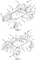
- the figure 1 illustrates an embodiment of a tractor 1 comprising a base structure 2 mounted on wheels 3a and 3b.
- the frame is closed and defines a central opening C'.
- a portion of the frame is made up of two side members 4 carrying at least one battery 8.
- the work area C′ is completely free and available to house tools, to create different work configurations and/or visibility areas towards the ground on which the work is in progress.
- the weight of the tractor is well distributed with a low center of gravity, which gives it excellent stability.
- the rear of the frame 2 is constituted by a transverse bar 15.
- the longitudinal members 4 and this transverse bar 15 form surfaces comprising a plurality of points 11 for positioning or fixing tools. These multiple attachment points 11 confer great modularity and a vast choice of tool positioning.
- a seat 14 and/or support for the operator can be positioned in this space.
- the tractor has at least two driving wheels 3a, in which an electric motor 13 is integrated.
- two idler wheels 3b make it possible to complete the assembly.
- a steering means makes it possible to steer the tractor.
- the changes of direction are effected by different speeds of rotation of the motorized wheels 3a.
- the idler wheels 3b by aligning themselves according to a force supplied by the wheels 3a, make it possible to carry out the changes of direction without constraint.
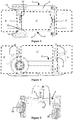
- the figures 3 and 4 illustrate the three working areas 7 that the tractor has. They are distributed at the front for zone A, in the peripheral frame for zone C' and at the rear for zone B.
- At least the work area C' extends above and below the frame 2.
- the architecture according to the invention makes it possible, for example, to provide first tool means 5 able to perform a task in the work zone A, second tool means 6 able to perform a task in the work zone B and other tool means and /or one or more operators can perform a task in zone C'.
- the tractor 1 also comprises an electronic box 12 provided to interface with the control means.
- the housing may include a tensiometer making it possible to adjust the speed of the motor or motors very precisely. Due to the use of an electric motor, the tractor can be controlled very precisely, for example in order to maintain a given speed over time and precisely. Depending on the needs and the tasks to be performed, the tractor can be controlled by an operator placed on the tractor or close to the latter, or by an autonomous control system, integrated into the electronic box 12.
- the non-motorized wheels 3b are of the idler wheel type, preferably located at the front of the tractor. They are mounted on a single pivoting transverse axis 10. This pivoting axis makes it possible, for example, to overcome obstacles or areas of uneven ground, as shown for example in figure 5 .
- the idler wheels allow the tractor 1 to have a center of rotation in the middle of the axle of the driving wheels 3a.
- the tractor can therefore make a U-turn on itself. This aspect is very practical and even essential in confined space, such as in a greenhouse.
- the electric driving wheels 3a are bidirectional. They can, thanks to the configuration of the tractor, sometimes be placed in traction and sometimes placed in propulsion.
- the tools can operate low to the ground and/or in the ground and/or up to the height desired and/or necessary for the work to be performed. Access to the floor is possible in zone C' thanks to the opening in the frame. This space is available to place one or more tools and/or one or more operators maneuvering the tools and/or a worker at ground level. If necessary, zone C' also makes it possible to make the link between the tools arranged in work zones A and B.
- the electric motors 13 placed in the wheels 3a make it possible to completely clear the work area C′. Indeed, no mechanical transmission element is present in this space. The work zone 7 is therefore totally free.
- the electric motors 13 have another advantage. Since the tractor 1 is compact and can be adapted to the requirements of restricted or confined spaces, it is preferable for the noise level to be as low as possible. The electric motors 13 make it possible to meet this requirement. Conversely, in a greenhouse, the sound emitted by a thermal engine tractor would be deafening. Flue gas fumes would also pose a problem for operators inside the greenhouse and pollute the crops. The electric motors are very quiet, emit no gas and are therefore stress-free for the operators and for the crops. A handy electric tractor such as the one presented is therefore perfectly suited for this type of work. The additional tasks which can be carried out in zones A, B and C' allow the tractor to intervene in an optimal way, in particular in a greenhouse, where the available space is very limited. The tractor is also well suited for working in livestock buildings.
- the architecture of the tractor 1 gives it a fairly low weight compared to the majority of machines of the same size.
- the tractor is particularly useful on fragile surfaces. Its weight allows it to leave the ground intact after its passage because it has a particularly advantageous weight/power ratio.
- the number of batteries 8 can be adapted, to lighten the tractor when working on fragile ground, or on the contrary by adding batteries in order to increase the autonomy and/or the power available for tools.
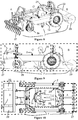
- the figures 6 and 7 represent an example of a harvesting operation.
- the tractor 1 is placed in traction mode. To do this, it suffices to reverse the position of the wheels 3a between them so that the grip of the tires is compatible with the forward movement in traction.
- a cutting bar 20 located in work zone B makes it possible to cut the plants to be harvested (leafy vegetables, aromatic/medicinal plants, etc.).
- the rotary comb 21 above the cutter bar makes it possible to assist the harvest and to drive it onto the conveyor 22 hitched in zone C′.
- This conveyor 22 is driven by an electric motor located in the rollers. The electric motor is connected to the control box 12.
- the conveyor makes it possible to convey the harvest in height, at the level of zone B.
- At A is hitched a platform 23 which makes it possible to accommodate an operator 24 and to store the current harvest in a tray 25 located in front of him.
- the cutter bar In working area B, the cutter bar is hitched to a three-point system 26.
- the cutting and folding movement is driven by a power take-off 9.
- the height and inclination of the blade are adjusted by the three point hitch.
- Blade speed is adjusted via PTO 9.
- the conveyor receives the crop from work area B and then carries it to work area C'.
- the rotation of the conveyor is ensured by an electric motor whose speed can be slaved to the advance of the tractor.
- a conventional tractor would not allow a conveyor to be hitched in the middle because of the cabin and the engine.
- the platform carried via a three-point hitch allows the operator 24 to stand while performing his work (sorting, packaging, etc.). He can also check the proper functioning of the tools from his location and control the device via a remote control.
- the platform can also accommodate the harvest in progress in the bin or by storing the crates next to the operator.
- tractor configuration 1 one person can steer and harvest while keeping operations running smoothly. Harvesting is precise thanks to the architecture of the tractor.
- the electric motor 13 and maneuverability are valuable assets for work under cover, such as greenhouses.
- the operator can harvest what is in his line of driving which differs for example from harvesters with conveyor hitched on the side of conventional tractors.
- the figures 8, 9 and 10 represent a planting operation.
- This configuration of the tractor 1 could also be a crop maintenance operation (hoeing, manual weeding, consolidation of the soil) by slightly modifying the tools.
- a vibro-cultivator 27 is hitched here in work area A, it allows the soil to be refined.
- two coulters 28 make it possible to open furrows. The operator sits close to the ground and can manually plant seedlings in the open furrows.
- the hitched implement has various rollers 29 which seal the ground on either side of the open furrow. This allows the soil to be closed and the plants to be "shod”.
- the vibrocultivator 27 is placed and the depth and inclination of the tines are adjusted via the three-point hitch.
- the coulters 28 open the furrows. They are hitched to the frame rails.
- the seat 14 of the operator 24 is located close to the earth so that the operator 24 is in contact with it. He can thus plant, weed, prune, etc., while driving.
- the control is done with a pedal 30 located under the feet (each of the pedals advances a wheel motor 13, like a chase). Moreover, he can see what is happening in front of him because zone C' is open. In a conventional tractor, it is impossible to reach the ground with his hands while driving because of the cab.
- rollers 29 are hitched by a conventional three-point system 26.
- the rollers 29 are spaced so as to plumb the soil without crushing the newly planted plants.
- the passage of the rollers 29 at the same time as the planting makes it possible to be perfectly aligned with the furrow.
- the operator 24 can work while driving, have access to the ground (which makes it possible to perform many tasks, some of which are only possible by human hand) and use three tools in a single pass.
- the figure 11 represents a semi operation.
- Three tools are hitched to tractor 1: in work area A, a rotary hoe 31 is used to refine and prepare the land.
- the drill 32 In work zone C′ the drill 32 is located so that the driver can monitor the operation (visual contact) then in work zone B a spreader 33 makes it possible to deposit fertilizers in the form of granules.
- the operator is seated high up in the work area C′, so as to be able to supervise the progress of the tractor 1 and the smooth running operations. It controls via a radio control 34 connected to the electronic unit 12.
- the rotary hoe 31 (trade name “ rotavator ”) is hitched to the tractor 1 by the three-point hitch 26.
- the hoe is driven by a front power take-off 9.
- the working depth is regulated by the position of the arms of the three-point linkage.
- the seeder 32 is hitched to the rails of the frame 2. It can be supplied with electricity by the batteries 8 (for pneumatic or electrically driven seeders, for example). The operator overlooks the drill and has direct visual contact with the operation (which is impossible in the classic tractor because of the engine). Another advantage is being able to monitor and adjust the seed drill directly without having to get out of tractor 1.
- the fertilizer is spread at the same time as the seeding, which avoids an additional pass and allows the soil to be preserved (especially when the seeding is carried out in limiting conditions).
- the spreader's rotary distributor is actuated by the rear PTO.
- the work area C' is such that the operator can monitor the semi while driving. In addition, he can intervene directly on the tool in the event of a problem.
- tractor 1 In the example of tractor 1 shown in figures 12a and 12b , the vehicle is provided with four motorized wheels 3a. It may for example have two steered wheels each driven by a steering jack 36 which, associated with the electronic differential, makes it possible to obtain the steering. This version still benefits from the three working areas 7.
- a standard coupling in zone A (the push bar is not shown), a standard hitch in zone B and a tool-carrying bar provided with a plurality of tool-carrying points 11 in zone C'.
- tractor 1 is controlled using a “joystick”.
- the configuration shown allows the operator to stand outside the vehicle, in order to control the tractor 1 remotely via a radio control 34.
- a robotic arm 35 makes it possible to illustrate the great diversity of the tools 5, 6 interfaceable with the tractor 1.
- the robotic arm 35 automatically performs tasks. Its perception can be provided by two cameras 40 or other tracking means positioned on a tool bar in the central zone C′.
- the tractor is equipped with a tracked train. At least two electric motors 13 drive at least two sprockets 38 which each drive a caterpillar 37. The direction of the tractor 1 is given by the difference in forward speed of the caterpillars 37.
- the peripheral frame 2 makes it possible to house the batteries 8 on the sides, in the longitudinal members 4. In this example, the batteries are located inside the tracked train 3 between the sprocket 38 and the tensioner roller 39. This makes it possible to have a frame 2 hollowed out in zone C′ and to have the three work zones 7.
- the control is carried out using a radio control 34 by an operator 24 not present on the tractor.
- the tractor can be autonomous and navigate the fields for example.
- a navigation system and GPS and/or RTK sensors for example, present in the electronic box can allow autonomous navigation.
- the working areas 7 A and B have a standard hitching system for hitching agricultural tools 5, 6.
- the central area C′ is equipped with a tool bar making it possible to hitch numerous tools, for example clippers, cultivator teeth, hyper spectral camera to detect fungal diseases, and others.
- the central zone C is equipped with a tilt-correction seat 14 .
- the seat 14 can be a driving position. Alternatively, it is only a transport seat 14 if the tractor is autonomous. In another variant, the tractor is controlled by speech, which allows the operator 24 to drive and/or carry out agricultural operations such as, for example, pruning, harvesting, and other operations, seated comfortably.
- the seat 14 tilts thanks to an electric actuator 41 which cooperates with the latter.
- the system is controlled in position thanks to an inclinometer present in the electronic box 12. This system makes it possible to move the center of gravity of the machine 1.
- the center of gravity is offset in the direction of the zone of the caterpillar 37 which has the no more need for grip: at the front when working and/or moving the tractor on uphill sections of land and at the rear on downhill sections. It is possible to ballast the seat 14 to accentuate the effect or even replace it with a mass.
Landscapes
- Engineering & Computer Science (AREA)
- Chemical & Material Sciences (AREA)
- Combustion & Propulsion (AREA)
- Transportation (AREA)
- Mechanical Engineering (AREA)
- Architecture (AREA)
- Structural Engineering (AREA)
- Agricultural Machines (AREA)
- Guiding Agricultural Machines (AREA)
Claims (8)
- Mehrzweck-Traktor (1), der eine Grundstruktur (2), Räder und/oder Raupen (3a, 3b), mindestens einen Elektromotor (13), erste Werkzeugeinrichtungen (5), die eine Arbeit in einem Arbeitsbereich A ausführen können, der sich auf einer ersten Seite der Grundstruktur befinden, zweite Werkzeugeinrichtungen (6), die eine Arbeit in einem Arbeitsbereich B ausführen können, der sich auf der zweiten Seite der Grundstruktur befindet, eine Steuereinrichtung enthält, wobei die Grundstruktur aus einem Umfangsrahmen (2) besteht, der eine Öffnung definiert, die einen zentralen Arbeitsbereich (C') bildet, wobei mindestens zwei der Räder und/oder Raupen eine integrierte Motorisierung enthalten, wobei der zentrale Arbeitsbereich (C') keinerlei Traktions- und/oder Antriebselement in Verbindung mit der Bewegung des Traktors enthält, wobei der Traktor dadurch gekennzeichnet ist, dass der Umfangsrahmen (2) mindestens zwei Längsträger (4) aufweist, die mindestens eine Batterie (8) tragen, die die Motoren (13) der Räder (3a) versorgt.
- Traktor (1) nach Anspruch 1, wobei der Arbeitsbereich C' sich oberhalb des Umfangsrahmens (2) verlängert.
- Traktor (1) nach einem der Ansprüche 1 oder 2, wobei der Arbeitsbereich C' sich unterhalb des Umfangsrahmens (2) verlängert.
- Traktor (1) nach einem der vorhergehenden Ansprüche, wobei der Umfangsrahmen eine Vielzahl von Positionierungspunkten (11) von Werkzeugen enthält.
- Traktor (1) nach einem der vorhergehenden Ansprüche, wobei der Arbeitsbereich C' sich zwischen den Rädern und/oder Raupen des Traktors befindet.
- Traktor (1) nach einem der vorhergehenden Ansprüche, der mindestens einen von den Batterien gespeisten Drehadapter (9) enthält.
- Traktor (1) nach einem der vorhergehenden Ansprüche, wobei mindestens zwei Räder (3b) von der Art Freilaufräder (3b) und vorzugsweise nicht motorisiert sind.
- Traktor (1) nach Anspruch 7, wobei die Freilaufräder auf eine einzige Schwenkachse (10) montiert sind.
Applications Claiming Priority (2)
| Application Number | Priority Date | Filing Date | Title |
|---|---|---|---|
| FR1770274A FR3063968B1 (fr) | 2017-03-20 | 2017-03-20 | Tracteur multitache electrique |
| PCT/IB2018/051558 WO2018172879A1 (fr) | 2017-03-20 | 2018-03-09 | Tracteur multitache electrique |
Publications (2)
| Publication Number | Publication Date |
|---|---|
| EP3601015A1 EP3601015A1 (de) | 2020-02-05 |
| EP3601015B1 true EP3601015B1 (de) | 2022-01-12 |
Family
ID=59409578
Family Applications (1)
| Application Number | Title | Priority Date | Filing Date |
|---|---|---|---|
| EP18712674.3A Active EP3601015B1 (de) | 2017-03-20 | 2018-03-09 | Elektrischer mehrzwecktractor |
Country Status (3)
| Country | Link |
|---|---|
| EP (1) | EP3601015B1 (de) |
| FR (2) | FR3063968B1 (de) |
| WO (1) | WO2018172879A1 (de) |
Families Citing this family (3)
| Publication number | Priority date | Publication date | Assignee | Title |
|---|---|---|---|---|
| GB2582261B (en) | 2019-03-01 | 2023-06-21 | Bamford Excavators Ltd | Working machine |
| CN112046629A (zh) * | 2020-08-31 | 2020-12-08 | 国家林业和草原局北京林业机械研究所 | 一种丘陵山地的造林抚育用动力平台及其造林抚育方法 |
| CN116918243A (zh) * | 2021-02-22 | 2023-10-20 | 意大利朗能科创有限公司 | 用于生产电力和用于处理农业土地的设备 |
Family Cites Families (12)
| Publication number | Priority date | Publication date | Assignee | Title |
|---|---|---|---|---|
| DE966154C (de) * | 1951-05-27 | 1957-09-12 | Saat & Erntetechnik Gmbh | Landwirtschaftliches, motorisch angetriebenes Fahrzeug |
| DE2443915A1 (de) | 1974-09-13 | 1976-04-01 | Ernst Weichel | Motor-landmaschine |
| DE2749783A1 (de) | 1976-11-11 | 1978-05-24 | Kubota Ltd | Schlepper mit seitlich versetztem aufbau |
| FR2416153A1 (fr) | 1978-02-03 | 1979-08-31 | Girault Pierre | Machine automotrice destinee a la recolte des betteraves |
| FR2606176A1 (fr) * | 1986-11-05 | 1988-05-06 | Iiriam | Procede et dispositif d'autoguidage d'un vehicule entre des obstacles dresses, et vehicule muni de ce dispositif |
| US5335739A (en) | 1992-12-30 | 1994-08-09 | Ian Pieterse | Agricultural vehicle |
| FR2856727B1 (fr) * | 2003-06-26 | 2005-10-21 | Sandvik Tamrock Secoma Sas | Vehicule porteur pour machine de foration ou de boulonnage |
| US7938210B2 (en) * | 2004-06-15 | 2011-05-10 | Massachusetts Institute Of Technology | Wheel-embedded suspension |
| FR3001101B1 (fr) * | 2013-01-18 | 2015-07-17 | Naio Technologies | Dispositif agricole automatise autonome |
| BR102013029530B1 (pt) | 2013-11-14 | 2020-07-21 | Cleusa De Fátima Lima De Macedo | equipamento colhedor de tubérculos |
| NL1040562C2 (en) * | 2013-12-22 | 2015-06-30 | Multitooltrac B V | Dynamically variable track width and electrically driven work in sight tractor and method of steering. |
| FR3032593B1 (fr) | 2015-02-13 | 2017-03-10 | Touti Terre | Engin agricole roulant comportant un siege transformable |
-
2017
- 2017-03-20 FR FR1770274A patent/FR3063968B1/fr not_active Expired - Fee Related
-
2018
- 2018-03-09 EP EP18712674.3A patent/EP3601015B1/de active Active
- 2018-03-09 WO PCT/IB2018/051558 patent/WO2018172879A1/fr not_active Ceased
- 2018-03-10 FR FR1870261A patent/FR3063969B1/fr active Active
Also Published As
| Publication number | Publication date |
|---|---|
| FR3063968A1 (fr) | 2018-09-21 |
| FR3063969A1 (fr) | 2018-09-21 |
| EP3601015A1 (de) | 2020-02-05 |
| FR3063968B1 (fr) | 2021-07-02 |
| WO2018172879A1 (fr) | 2018-09-27 |
| FR3063969B1 (fr) | 2021-05-28 |
Similar Documents
| Publication | Publication Date | Title |
|---|---|---|
| EP1345487B1 (de) | Präzisionsschälpflug mit eingebauten sähelementen | |
| CA1257886A (fr) | Vehicule tout terrain a applications multiples | |
| US20160088786A1 (en) | Active coulter planting system | |
| BE491255A (de) | ||
| WO2014111387A1 (fr) | Dispositif agricole automatisé autonome | |
| EP1976367B1 (de) | Bodenbearbeitungsmaschine in der art eines vertikalscheibenpfluges | |
| WO2018172879A1 (fr) | Tracteur multitache electrique | |
| EP2852521B1 (de) | Anhänger mit einer deportierten anspannenvorrichtung | |
| EP3645376A1 (de) | Karosserie eines landwirtschaftlichen fahrzeugs mit verstellbarer breite und landwirtschaftliches fahrzeug | |
| KR102389383B1 (ko) | 무한궤도형 주행부를 포함하는 제초 로봇 | |
| WO2011114016A1 (fr) | Tracteur enjambeur | |
| CA3158224A1 (fr) | Robot autonome | |
| US20170142956A1 (en) | Utility Walk-Behind Vehicle for Agriculture and Property Maintenance | |
| KR200483458Y1 (ko) | 제초기 및 관리기의 위치를 선택적으로 가변시킬 수 있는 무한궤도 운반기 | |
| FR2687534A1 (fr) | Machine de preparation des sols. | |
| FR2996981A1 (fr) | Engin agricole motorise destine a etre utilise notamment dans les metiers du maraichage | |
| FR2866195A1 (fr) | Engin agraire ultraleger, automoteur, ou tracte, en particulier par un animal, pour le travail du sol par ameublissement | |
| FR2953365A1 (fr) | Tracteur enjambeur | |
| EP1533214A1 (de) | Werkzeugträger mit drei Rädern | |
| US20190016397A1 (en) | Row-crop tractor | |
| JP2020141561A (ja) | 野菜収穫機 | |
| EP0030908B1 (de) | Landwirtschaftliche Bodenbearbeitungsmaschine | |
| BE487598A (de) | ||
| FR2467528A1 (fr) | Appareil porteur-tracteur pour travaux agricoles | |
| FR2862477A1 (fr) | Dispositif de dechaumage a double modules |
Legal Events
| Date | Code | Title | Description |
|---|---|---|---|
| STAA | Information on the status of an ep patent application or granted ep patent |
Free format text: STATUS: UNKNOWN |
|
| STAA | Information on the status of an ep patent application or granted ep patent |
Free format text: STATUS: THE INTERNATIONAL PUBLICATION HAS BEEN MADE |
|
| PUAI | Public reference made under article 153(3) epc to a published international application that has entered the european phase |
Free format text: ORIGINAL CODE: 0009012 |
|
| STAA | Information on the status of an ep patent application or granted ep patent |
Free format text: STATUS: REQUEST FOR EXAMINATION WAS MADE |
|
| 17P | Request for examination filed |
Effective date: 20190927 |
|
| AK | Designated contracting states |
Kind code of ref document: A1 Designated state(s): AL AT BE BG CH CY CZ DE DK EE ES FI FR GB GR HR HU IE IS IT LI LT LU LV MC MK MT NL NO PL PT RO RS SE SI SK SM TR |
|
| AX | Request for extension of the european patent |
Extension state: BA ME |
|
| DAV | Request for validation of the european patent (deleted) | ||
| DAX | Request for extension of the european patent (deleted) | ||
| STAA | Information on the status of an ep patent application or granted ep patent |
Free format text: STATUS: EXAMINATION IS IN PROGRESS |
|
| 17Q | First examination report despatched |
Effective date: 20210303 |
|
| GRAP | Despatch of communication of intention to grant a patent |
Free format text: ORIGINAL CODE: EPIDOSNIGR1 |
|
| STAA | Information on the status of an ep patent application or granted ep patent |
Free format text: STATUS: GRANT OF PATENT IS INTENDED |
|
| INTG | Intention to grant announced |
Effective date: 20210910 |
|
| GRAS | Grant fee paid |
Free format text: ORIGINAL CODE: EPIDOSNIGR3 |
|
| GRAA | (expected) grant |
Free format text: ORIGINAL CODE: 0009210 |
|
| STAA | Information on the status of an ep patent application or granted ep patent |
Free format text: STATUS: THE PATENT HAS BEEN GRANTED |
|
| RAP3 | Party data changed (applicant data changed or rights of an application transferred) |
Owner name: SABI AGRI |
|
| AK | Designated contracting states |
Kind code of ref document: B1 Designated state(s): AL AT BE BG CH CY CZ DE DK EE ES FI FR GB GR HR HU IE IS IT LI LT LU LV MC MK MT NL NO PL PT RO RS SE SI SK SM TR |
|
| REG | Reference to a national code |
Ref country code: GB Ref legal event code: FG4D Free format text: NOT ENGLISH |
|
| REG | Reference to a national code |
Ref country code: CH Ref legal event code: EP |
|
| REG | Reference to a national code |
Ref country code: DE Ref legal event code: R096 Ref document number: 602018029488 Country of ref document: DE |
|
| REG | Reference to a national code |
Ref country code: IE Ref legal event code: FG4D Free format text: LANGUAGE OF EP DOCUMENT: FRENCH |
|
| REG | Reference to a national code |
Ref country code: AT Ref legal event code: REF Ref document number: 1462188 Country of ref document: AT Kind code of ref document: T Effective date: 20220215 |
|
| REG | Reference to a national code |
Ref country code: LT Ref legal event code: MG9D |
|
| REG | Reference to a national code |
Ref country code: NL Ref legal event code: MP Effective date: 20220112 |
|
| REG | Reference to a national code |
Ref country code: AT Ref legal event code: MK05 Ref document number: 1462188 Country of ref document: AT Kind code of ref document: T Effective date: 20220112 |
|
| PG25 | Lapsed in a contracting state [announced via postgrant information from national office to epo] |
Ref country code: NL Free format text: LAPSE BECAUSE OF FAILURE TO SUBMIT A TRANSLATION OF THE DESCRIPTION OR TO PAY THE FEE WITHIN THE PRESCRIBED TIME-LIMIT Effective date: 20220112 |
|
| PG25 | Lapsed in a contracting state [announced via postgrant information from national office to epo] |
Ref country code: SE Free format text: LAPSE BECAUSE OF FAILURE TO SUBMIT A TRANSLATION OF THE DESCRIPTION OR TO PAY THE FEE WITHIN THE PRESCRIBED TIME-LIMIT Effective date: 20220112 Ref country code: RS Free format text: LAPSE BECAUSE OF FAILURE TO SUBMIT A TRANSLATION OF THE DESCRIPTION OR TO PAY THE FEE WITHIN THE PRESCRIBED TIME-LIMIT Effective date: 20220112 Ref country code: PT Free format text: LAPSE BECAUSE OF FAILURE TO SUBMIT A TRANSLATION OF THE DESCRIPTION OR TO PAY THE FEE WITHIN THE PRESCRIBED TIME-LIMIT Effective date: 20220512 Ref country code: NO Free format text: LAPSE BECAUSE OF FAILURE TO SUBMIT A TRANSLATION OF THE DESCRIPTION OR TO PAY THE FEE WITHIN THE PRESCRIBED TIME-LIMIT Effective date: 20220412 Ref country code: LT Free format text: LAPSE BECAUSE OF FAILURE TO SUBMIT A TRANSLATION OF THE DESCRIPTION OR TO PAY THE FEE WITHIN THE PRESCRIBED TIME-LIMIT Effective date: 20220112 Ref country code: HR Free format text: LAPSE BECAUSE OF FAILURE TO SUBMIT A TRANSLATION OF THE DESCRIPTION OR TO PAY THE FEE WITHIN THE PRESCRIBED TIME-LIMIT Effective date: 20220112 Ref country code: ES Free format text: LAPSE BECAUSE OF FAILURE TO SUBMIT A TRANSLATION OF THE DESCRIPTION OR TO PAY THE FEE WITHIN THE PRESCRIBED TIME-LIMIT Effective date: 20220112 Ref country code: BG Free format text: LAPSE BECAUSE OF FAILURE TO SUBMIT A TRANSLATION OF THE DESCRIPTION OR TO PAY THE FEE WITHIN THE PRESCRIBED TIME-LIMIT Effective date: 20220412 |
|
| PG25 | Lapsed in a contracting state [announced via postgrant information from national office to epo] |
Ref country code: PL Free format text: LAPSE BECAUSE OF FAILURE TO SUBMIT A TRANSLATION OF THE DESCRIPTION OR TO PAY THE FEE WITHIN THE PRESCRIBED TIME-LIMIT Effective date: 20220112 Ref country code: LV Free format text: LAPSE BECAUSE OF FAILURE TO SUBMIT A TRANSLATION OF THE DESCRIPTION OR TO PAY THE FEE WITHIN THE PRESCRIBED TIME-LIMIT Effective date: 20220112 Ref country code: GR Free format text: LAPSE BECAUSE OF FAILURE TO SUBMIT A TRANSLATION OF THE DESCRIPTION OR TO PAY THE FEE WITHIN THE PRESCRIBED TIME-LIMIT Effective date: 20220413 Ref country code: FI Free format text: LAPSE BECAUSE OF FAILURE TO SUBMIT A TRANSLATION OF THE DESCRIPTION OR TO PAY THE FEE WITHIN THE PRESCRIBED TIME-LIMIT Effective date: 20220112 Ref country code: AT Free format text: LAPSE BECAUSE OF FAILURE TO SUBMIT A TRANSLATION OF THE DESCRIPTION OR TO PAY THE FEE WITHIN THE PRESCRIBED TIME-LIMIT Effective date: 20220112 |
|
| PG25 | Lapsed in a contracting state [announced via postgrant information from national office to epo] |
Ref country code: IS Free format text: LAPSE BECAUSE OF FAILURE TO SUBMIT A TRANSLATION OF THE DESCRIPTION OR TO PAY THE FEE WITHIN THE PRESCRIBED TIME-LIMIT Effective date: 20220512 |
|
| REG | Reference to a national code |
Ref country code: DE Ref legal event code: R097 Ref document number: 602018029488 Country of ref document: DE |
|
| PG25 | Lapsed in a contracting state [announced via postgrant information from national office to epo] |
Ref country code: SM Free format text: LAPSE BECAUSE OF FAILURE TO SUBMIT A TRANSLATION OF THE DESCRIPTION OR TO PAY THE FEE WITHIN THE PRESCRIBED TIME-LIMIT Effective date: 20220112 Ref country code: SK Free format text: LAPSE BECAUSE OF FAILURE TO SUBMIT A TRANSLATION OF THE DESCRIPTION OR TO PAY THE FEE WITHIN THE PRESCRIBED TIME-LIMIT Effective date: 20220112 Ref country code: RO Free format text: LAPSE BECAUSE OF FAILURE TO SUBMIT A TRANSLATION OF THE DESCRIPTION OR TO PAY THE FEE WITHIN THE PRESCRIBED TIME-LIMIT Effective date: 20220112 Ref country code: MC Free format text: LAPSE BECAUSE OF FAILURE TO SUBMIT A TRANSLATION OF THE DESCRIPTION OR TO PAY THE FEE WITHIN THE PRESCRIBED TIME-LIMIT Effective date: 20220112 Ref country code: EE Free format text: LAPSE BECAUSE OF FAILURE TO SUBMIT A TRANSLATION OF THE DESCRIPTION OR TO PAY THE FEE WITHIN THE PRESCRIBED TIME-LIMIT Effective date: 20220112 Ref country code: DK Free format text: LAPSE BECAUSE OF FAILURE TO SUBMIT A TRANSLATION OF THE DESCRIPTION OR TO PAY THE FEE WITHIN THE PRESCRIBED TIME-LIMIT Effective date: 20220112 Ref country code: CZ Free format text: LAPSE BECAUSE OF FAILURE TO SUBMIT A TRANSLATION OF THE DESCRIPTION OR TO PAY THE FEE WITHIN THE PRESCRIBED TIME-LIMIT Effective date: 20220112 |
|
| REG | Reference to a national code |
Ref country code: CH Ref legal event code: PL |
|
| PLBE | No opposition filed within time limit |
Free format text: ORIGINAL CODE: 0009261 |
|
| STAA | Information on the status of an ep patent application or granted ep patent |
Free format text: STATUS: NO OPPOSITION FILED WITHIN TIME LIMIT |
|
| PG25 | Lapsed in a contracting state [announced via postgrant information from national office to epo] |
Ref country code: AL Free format text: LAPSE BECAUSE OF FAILURE TO SUBMIT A TRANSLATION OF THE DESCRIPTION OR TO PAY THE FEE WITHIN THE PRESCRIBED TIME-LIMIT Effective date: 20220112 |
|
| REG | Reference to a national code |
Ref country code: BE Ref legal event code: MM Effective date: 20220331 |
|
| 26N | No opposition filed |
Effective date: 20221013 |
|
| PG25 | Lapsed in a contracting state [announced via postgrant information from national office to epo] |
Ref country code: LU Free format text: LAPSE BECAUSE OF NON-PAYMENT OF DUE FEES Effective date: 20220309 Ref country code: LI Free format text: LAPSE BECAUSE OF NON-PAYMENT OF DUE FEES Effective date: 20220331 Ref country code: IE Free format text: LAPSE BECAUSE OF NON-PAYMENT OF DUE FEES Effective date: 20220309 Ref country code: CH Free format text: LAPSE BECAUSE OF NON-PAYMENT OF DUE FEES Effective date: 20220331 |
|
| PG25 | Lapsed in a contracting state [announced via postgrant information from national office to epo] |
Ref country code: SI Free format text: LAPSE BECAUSE OF FAILURE TO SUBMIT A TRANSLATION OF THE DESCRIPTION OR TO PAY THE FEE WITHIN THE PRESCRIBED TIME-LIMIT Effective date: 20220112 Ref country code: BE Free format text: LAPSE BECAUSE OF NON-PAYMENT OF DUE FEES Effective date: 20220331 |
|
| PG25 | Lapsed in a contracting state [announced via postgrant information from national office to epo] |
Ref country code: IT Free format text: LAPSE BECAUSE OF FAILURE TO SUBMIT A TRANSLATION OF THE DESCRIPTION OR TO PAY THE FEE WITHIN THE PRESCRIBED TIME-LIMIT Effective date: 20220112 |
|
| PG25 | Lapsed in a contracting state [announced via postgrant information from national office to epo] |
Ref country code: MK Free format text: LAPSE BECAUSE OF FAILURE TO SUBMIT A TRANSLATION OF THE DESCRIPTION OR TO PAY THE FEE WITHIN THE PRESCRIBED TIME-LIMIT Effective date: 20220112 Ref country code: CY Free format text: LAPSE BECAUSE OF FAILURE TO SUBMIT A TRANSLATION OF THE DESCRIPTION OR TO PAY THE FEE WITHIN THE PRESCRIBED TIME-LIMIT Effective date: 20220112 |
|
| PG25 | Lapsed in a contracting state [announced via postgrant information from national office to epo] |
Ref country code: HU Free format text: LAPSE BECAUSE OF FAILURE TO SUBMIT A TRANSLATION OF THE DESCRIPTION OR TO PAY THE FEE WITHIN THE PRESCRIBED TIME-LIMIT; INVALID AB INITIO Effective date: 20180309 |
|
| PG25 | Lapsed in a contracting state [announced via postgrant information from national office to epo] |
Ref country code: MT Free format text: LAPSE BECAUSE OF FAILURE TO SUBMIT A TRANSLATION OF THE DESCRIPTION OR TO PAY THE FEE WITHIN THE PRESCRIBED TIME-LIMIT Effective date: 20220112 |
|
| PG25 | Lapsed in a contracting state [announced via postgrant information from national office to epo] |
Ref country code: TR Free format text: LAPSE BECAUSE OF FAILURE TO SUBMIT A TRANSLATION OF THE DESCRIPTION OR TO PAY THE FEE WITHIN THE PRESCRIBED TIME-LIMIT Effective date: 20220112 |
|
| PGFP | Annual fee paid to national office [announced via postgrant information from national office to epo] |
Ref country code: GB Payment date: 20260121 Year of fee payment: 9 |
|
| PGFP | Annual fee paid to national office [announced via postgrant information from national office to epo] |
Ref country code: DE Payment date: 20260122 Year of fee payment: 9 |
|
| PGFP | Annual fee paid to national office [announced via postgrant information from national office to epo] |
Ref country code: FR Payment date: 20260121 Year of fee payment: 9 |