EP3601082B1 - Bouchon de fermeture pour l'emballage d'un produit cosmétique - Google Patents
Bouchon de fermeture pour l'emballage d'un produit cosmétique Download PDFInfo
- Publication number
- EP3601082B1 EP3601082B1 EP18712884.8A EP18712884A EP3601082B1 EP 3601082 B1 EP3601082 B1 EP 3601082B1 EP 18712884 A EP18712884 A EP 18712884A EP 3601082 B1 EP3601082 B1 EP 3601082B1
- Authority
- EP
- European Patent Office
- Prior art keywords
- skirt
- cap
- internal skirt
- thickness
- internal
- Prior art date
- Legal status (The legal status is an assumption and is not a legal conclusion. Google has not performed a legal analysis and makes no representation as to the accuracy of the status listed.)
- Active
Links
Images


Classifications
-
- B—PERFORMING OPERATIONS; TRANSPORTING
- B65—CONVEYING; PACKING; STORING; HANDLING THIN OR FILAMENTARY MATERIAL
- B65D—CONTAINERS FOR STORAGE OR TRANSPORT OF ARTICLES OR MATERIALS, e.g. BAGS, BARRELS, BOTTLES, BOXES, CANS, CARTONS, CRATES, DRUMS, JARS, TANKS, HOPPERS, FORWARDING CONTAINERS; ACCESSORIES, CLOSURES, OR FITTINGS THEREFOR; PACKAGING ELEMENTS; PACKAGES
- B65D41/00—Caps, e.g. crown caps or crown seals, i.e. members having parts arranged for engagement with the external periphery of a neck or wall defining a pouring opening or discharge aperture; Protective cap-like covers for closure members, e.g. decorative covers of metal foil or paper
- B65D41/02—Caps or cap-like covers without lines of weakness, tearing strips, tags, or like opening or removal devices
- B65D41/04—Threaded or like caps or cap-like covers secured by rotation
-
- B—PERFORMING OPERATIONS; TRANSPORTING
- B29—WORKING OF PLASTICS; WORKING OF SUBSTANCES IN A PLASTIC STATE IN GENERAL
- B29D—PRODUCING PARTICULAR ARTICLES FROM PLASTICS OR FROM SUBSTANCES IN A PLASTIC STATE
- B29D1/00—Producing articles with screw-threads
Definitions
- the present invention relates to a closure cap or lid that is able to be fastened removably to a container produced for example in the form of a pot, bottle, etc.
- the invention is particularly suitable for sealing containers for storing cosmetic, pharmaceutical or dermato-pharmaceutical products.
- Such products can, for example, be dispensed in an aqueous form, in the form of an oil, a milk, a cream, a paste, a gel, a foam, etc.
- closure caps produced by moulding a synthetic material.
- a cap comprises an internal skirt provided on the inside with a screw thread for fastening to the associated container, an external enclosing skirt surrounding the internal skirt and a front wall to which the skirts are joined.
- Such caps are also widely used in the field of sealing bottles containing liquids to be drunk.
- Patent Application FR-A1-2 523 551 For more details on the design of these caps, reference may be made for example to the Patent Application FR-A1-2 523 551 .
- the internal skirt of the cap has a substantially constant thickness.
- this constant thickness of the internal skirt leads to the formation of shrinkage marks or deformations on the upper face of the front wall of the cap during the cooling of the material. These marks associated with the shrinkage of the synthetic material are visible to the consumer.
- Patent application US-A1-2014/0103043 discloses a cap according to the preamble of claim 1, provided with inner and outer skirts extending axially from a front wall, wherein the inner skirt has a reduced thickness in the junction zone with the front wall.
- the subject of the invention is a closure cap for a container, comprising an internal skirt for fastening said cap to the container, an external skirt radially surrounding said internal skirt at least partially, and a front wall from which said internal and external skirts extend.
- the cap is produced by moulding at least one synthetic material.
- the internal skirt has a variable thickness in the direction of its axial length. Said thickness is at a minimum at least for a proximal portion of said skirt which extends from the front wall.
- the "thickness of the internal skirt” is understood to be the thickness measured perpendicularly to the axis of the cap between the outer surface and the bore of said skirt. This thickness is measured independently of the reliefs that can be provided on the bore of the internal skirt, for example a screw thread, and independently of the reliefs or recesses that can be formed on the outer surface of the skirt.
- the local reduction in the thickness of the internal skirt in the junction zone with the front wall makes it possible to enable uniform cooling of the cap after moulding.
- the risk of the appearance of shrinkage marks on the front wall of the cap is limited.
- an undercut part is formed in the outer surface thereof in the junction zone with the front wall.
- "Undercut part” is understood to be the portions of the outer surface of the internal skirt which oppose the demoulding of the cap.
- the internal skirt comprises the proximal portion with a thickness E 1 that is substantially constant, a distal portion with a thickness E 2 that is substantially constant and greater than the thickness E 1 , and a connecting portion that connects the proximal portion and the distal portion and has a variable thickness E 3 along its length. At least the connecting portion forms the undercut part of the internal skirt.
- the variation in the thickness E 3 of the connecting portion may be gradual.
- the axial length of the proximal portion of the internal skirt varies around the circumference of said skirt.
- the variation in the axial length of the proximal portion of the internal skirt is linear over a first angular sector of 180° of said skirt with a coefficient having a value C, and linear over a successive second angular sector of 180° of said skirt with a coefficient having a value -C.
- the axis of the connecting portion of the internal skirt is inclined with respect to the central axis of the cap.
- contact between this portion and the outer core of the mould is not continuous in the circumferential direction in a plane perpendicular to the axis of the cap.
- the linear variation in the axial length of the proximal portion is such that the orthogonal projection onto the central axis of said cap of the proximal point of a lower edge of the connecting portion of the internal skirt is offset axially towards the front wall with respect to the orthogonal projection onto said axis of the distal point of an upper edge of said connecting portion.
- proximal point of the lower edge of the connecting portion is understood to be the point of this lower edge which is situated axially closest to the front wall.
- distal point of the upper edge of the connecting portion is understood to be the point of the upper edge which is situated axially furthest away from the front wall.
- Such a disposition ensures that the orthogonal projection onto the central axis of the cap of the contact line between the outer core of the mould and the connecting portion of the internal skirt that is situated closest to the front wall does not intersect or overlap the contact line between this core and the connecting portion situated furthest away from the front wall. This further limits the risk of the appearance of surface defects on the front wall of the cap, it being possible for said surface defects to be formed by the demoulding force exerted by the outer core of the mould.
- this variation may be sinusoidal around said circumference.
- the proximal portion of the internal skirt of the cap thus comprises a plurality of undulations which each extend axially and are successive in the circumferential direction. In this zone, contact between the internal skirt and the outer core of the mould is discontinuous in the circumferential direction in a plane perpendicular to the axis of the cap.
- the internal skirt is provided on the inside with at least one screw thread for fastening said cap to the container.
- Said screw thread may be helical in order to screw said cap onto the container.
- the latter may accommodate an inserted seal mounted in abutment against the front wall of the cap.
- this axial retention may be realized by the screw thread of the internal skirt.
- the cap according to the invention may be used for a container for storing a cosmetic, or dermatological, product, notably in the form of a cream, foam, gel, milk or paste. It may, notably, be a body hygiene product, a hair styling product, a skincare or haircare product, a makeup product, or a sun protection product.
- the cap may also be used in other applications, for example for sealing bottles containing liquids to be drunk.
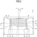
- Figure 1 shows a lid or cap, denoted by the overall reference numeral 10, which is provided to be screwed onto a container for storing a product (not shown).
- the cap 10 is shown in a position presumed to be vertical and extends along a central median axis 12.
- the cap 10 is produced in one piece by moulding a synthetic material, for example polypropylene (PP), polyethylene (PE), acrylonitrile butadiene styrene (ABS), polyethylene terephthalate (PET), etc.
- PP polypropylene
- PE polyethylene
- ABS acrylonitrile butadiene styrene
- PET polyethylene terephthalate
- the cap 10 is designed to limit the appearance of any surface defects associated with manufacturing by moulding.
- the cap 10 comprises an upper front end wall 14, an internal skirt 16 and a peripheral external skirt 18 surrounding the internal skirt.
- the skirts 16, 18 are centred on the axis 12.
- the skirts 16, 18 extend axially from the lower face of the front wall 14.
- the front wall 14 extends radially.
- the external skirt 18 which is coaxial with the axis 12, axially continues a large-diameter edge of the front wall 14.
- the external skirt 18 radially surrounds the internal skirt 16, remaining radially away from the latter.
- the skirt 18 in this case extends axially beyond the internal skirt 16.
- the external skirt 18 forms an enclosing skirt of the cap 10.
- the external skirt 18 has a circular cross section.
- the internal skirt 16 of the cap is delimited in the radial direction by an outer surface 16a and by an opposite inner surface forming a bore 16b.
- the bore 16b is coaxial with the axis 12 and has a cylindrical shape.
- the internal skirt 16 also comprises a front face 16c forming the free end of said skirt. The front face 16c is in this case set back axially from the external skirt 18.
- the internal skirt 16 comprises a helical screw thread 19 for screwing the cap 10 onto the associated container.
- the screw thread 19 extends radially inwards from the bore 16b.
- the screw thread 19 is in this case continuous in the circumferential direction.
- the internal skirt 16 allows the cap to be mounted on and fastened to the associated storage container.
- the screw thread 19 comprises two threads.
- the screw thread 19 may comprise a single thread or a greater number of threads than two.
- an undercut part 20 is formed on the outer surface 16a of the internal skirt.
- the undercut part 20 is formed such that, in the junction zone of the internal skirt 16 with the lower face of the front wall 14, the thickness of the internal skirt 16 is reduced compared with the thickness of the rest of the skirt.
- the internal skirt 16 has a variable thickness in the direction of its axial length, this thickness being at a minimum in the junction zone with the front wall 14.
- the internal skirt 16 comprises a proximal portion 22 with a thickness E 1 that is substantially constant, said proximal portion 22 extending from the lower face of the front wall 14, a distal portion 24 with a thickness E 2 that is substantially constant and greater than the thickness E 1 , and a connecting portion 26 connecting said portions together.
- the connecting portion 26 has a thickness E 3 that varies along its length. The thickness of the connecting portion 26 increases gradually from the proximal portion 22 to the distal portion 24.
- the connecting portion 26 has a frustoconical shape.
- the thickness E 1 of the proximal portion 22 is the minimum thickness of the internal skirt 16, while the thickness E 2 of the distal portion 24 is the maximum thickness of said skirt.
- the thickness E 1 of the proximal portion 22 may be equal to 0.6 mm at the junction with the front wall 14, and the thickness E 2 of the distal portion 24 may be equal to 1.3 mm.
- the axial length of the proximal portion 22 varies around the circumference of the internal skirt 16.
- the variation in the axial length of the proximal portion 22 is linear over a first angular sector of 180° with a coefficient having a value C, and linear over a successive second angular sector of 180° with a coefficient having a value -C.
- the connecting portion 26 is inclined with respect to the axis 12 of the cap.
- the longitudinal axis 28 of the connecting portion 26 forms, with the central axis 12 of the cap, a non-zero inclination angle ⁇ .
- the value of the angle ⁇ may be, for example, between 8° and 15°, and preferably equal to 10°.
- the connecting portion 26 is delimited in the axial direction by a circular upper edge 26a and a circular lower edge 26b.
- the variation in the axial length of the proximal portion 22 of the internal skirt is chosen such that the orthogonal projection onto the axis 12 of the cap of the proximal point, referenced P prox , of the lower edge 26b is offset axially towards the front wall with respect to the orthogonal projection onto the axis of the distal point, referenced P dist , of the upper edge 26a.
- the proximal portion 22 of the internal skirt extends axially between the upper edge 26a of the connecting portion and the lower face of the front wall 14.
- the proximal portion 22 is in the form of a frustoconical portion that is centred on the axis 12 of the cap and flares radially outwards towards the front face 16c of the internal skirt.
- the gradient of the proximal portion 22 is low, for example around 2° to 3°.
- the undercut part 20 of the internal skirt is formed by the proximal portion 22 and the connecting portion 26.
- the proximal portion 22 may be in the form of an axial cylindrical portion. In this case, the undercut part 20 of the internal skirt is formed only by the connecting portion 26.
- the distal portion 24 of the internal skirt extends axially from the lower edge 26b.
- the distal portion 24 delimits the front face 16c of the internal skirt.
- the distal portion 24 has a cylindrical shape in this case.
- the cap 10 comprises a plurality of grooves 30 formed in the outer surface 16a of the internal skirt.
- the grooves 30 are parallel to one another.
- the grooves 30 are disposed axially between the front face 16c of the skirt and the upper edge 26a of the connecting portion.
- Each groove 30 extends radially into the thickness of the internal skirt 16 without leading out into the bore 16b of said internal skirt.
- the grooves 30 do not lead out onto the front face 16c.
- the grooves 30 extend in this case axially along the outer surface 16a.
- the grooves 30 are spaced apart from one another in the circumferential direction, in this case regularly.
- the grooves 30 in this case have an axial dimension which varies gradually in the circumferential direction around the outer surface 16a.
- the grooves 30 form anti-rotation means during the demoulding of the cap 10.
- Figure 4 schematically shows, in cross section, the cap 10 in a moulding position inside a manufacturing mould 32.
- the mould 32 of axis 34 coaxial with the axis 12 of the cap, mainly comprises a matrix 36 provided with a cavity 38 with a shape corresponding to the outer shape of the cap, and an inner core 40 and outer core 42 for moulding the inner shapes thereof.
- the mould 32 also comprises an ejection support 44 interposed axially between the matrix 36 and the outer core 42.
- the inner core 40 of axis 34, comprises, on its outer surface, helical grooves 46 for moulding the threads of the screw thread 19 of the internal skirt of the cap.
- the outer core 42 has an annular shape.
- the outer core 42 radially surrounds the inner core 40 and has a shape complementary to that of the bore of the external skirt 18 of the cap and of the outer surface of the internal skirt 16.
- the cap 10 is demoulded from the mould 32 as follows: In a first step, the cores 40, 42 and the cap 10 are withdrawn jointly from the matrix 36 of the mould.
- the inner core 40 is unscrewed from the bore of the internal skirt 16 of the cap.
- the grooves 30 made in the outer surface of the internal skirt 16 prevent the cap from rotating during this step of unscrewing the inner core 40.
- the grooves 30 cooperate with complementary protuberances 50 of the bore of the outer core 42.
- the cap 10 is demoulded from the outer core 42 by way of the ejection support 44.
- the undercut part 20 of the outer surface of the internal skirt 16 and the grooves 30 are demoulded by force.
- the outer core 42 exerts a demoulding force which tends to deform the internal skirt 16 of the cap radially inwards and to axially stretch said skirt towards the front face 16c.
- the force exerted by the outer core 42 on the outer surface 16a of the internal skirt in the vicinity of the front wall 14 is limited.
- the demoulding force is exerted by the core 42 over a limited angular sector.
- the internal skirt 16 of the cap is deformed radially inwards and stretched axially only in this angular sector.
- a double-skirt cap is provided on which shrinkage marks that can be formed on the upper face of the front wall of the cap are reduced to a particularly significant extent compared with those which are usually visible with a conventional design of the internal skirt with a constant thickness. This is made possible by the local reduction in the thickness of the internal skirt in the junction zone with the front wall, which enables uniform cooling of the cap after moulding.
Landscapes
- Engineering & Computer Science (AREA)
- Mechanical Engineering (AREA)
- Closures For Containers (AREA)
Claims (8)
- Capsule de fermeture pour récipient s'étendant selon un axe (12) central et comprenant une jupe interne (16) pour la fixation de ladite capsule sur le récipient, une jupe externe (18) entourant radialement au moins en partie ladite jupe interne, et une paroi frontale (14) s'étendant radialement et à partir de laquelle s'étendent axialement lesdites jupes interne et externe, la capsule étant réalisée par moulage d'au moins une matière synthétique, la jupe interne (16) présentant une épaisseur variable dans le sens de sa longueur axiale, ladite épaisseur étant minimale au moins pour une portion proximale (22) de ladite jupe qui s'étend à partir de la paroi frontale (14), la jupe interne (16) comprenant la portion proximale (22) d'épaisseur E1 sensiblement constante, une portion distale (24) d'épaisseur E2 sensiblement constante et supérieure à l'épaisseur E1, et une portion de liaison (26) reliant la portion proximale et la portion distale et présentant une épaisseur E3 variable le long de sa longueur, caractérisée en ce que la longueur axiale de la portion proximale (22) de la jupe interne (16) varie autour de la circonférence de ladite jupe interne (16).
- Capsule selon la revendication 1, dans laquelle la variation de l'épaisseur E3 de la portion de liaison (26) est progressive.
- Capsule selon la revendication 1 ou 2, dans laquelle la portion de liaison (26) est de forme tronconique.
- Capsule selon l'une quelconque des revendications précédentes, dans laquelle la variation de la longueur axiale de la portion proximale (22) de la jupe interne est linéaire sur un premier secteur angulaire de 180° de ladite jupe avec un coefficient ayant une valeur C, et linéaire sur un second secteur angulaire de 180° successif de ladite jupe avec un coefficient ayant une valeur - C.
- Capsule selon la revendication 4, dans laquelle la variation linéaire de la longueur axiale de la portion proximale (22) est telle que la projection orthogonale sur l'axe (12) central de ladite capsule du point proximal (Pprox) d'un bord inférieur (26b) de la portion de liaison de la jupe interne est décalée axialement du côté de la paroi frontale (14) par rapport à la projection orthogonale sur ledit axe du point distal (Pdist) d'un bord supérieur (26a) de ladite portion de liaison.
- Capsule selon l'une quelconque des revendications 1 à 3, dans laquelle la variation de la longueur axiale de la portion proximale (22) de la jupe interne est sinusoïdale autour de la circonférence de ladite jupe.
- Capsule selon l'une quelconque des revendications précédentes, dans laquelle la jupe interne (16) est pourvue intérieurement d'au moins un filetage (19) pour la fixation de ladite capsule sur le récipient.
- Dispositif de conditionnement d'un produit, notamment d'un produit cosmétique, comprenant un récipient de stockage dudit produit muni d'un col, et une capsule de fermeture selon l'une quelconque des revendications précédentes montée et fixée sur ledit col.
Applications Claiming Priority (2)
| Application Number | Priority Date | Filing Date | Title |
|---|---|---|---|
| FR1752514A FR3064250B1 (fr) | 2017-03-27 | 2017-03-27 | Capsule de fermeture pour dispositif de conditionnement d'un produit, notamment d'un produit cosmetique |
| PCT/EP2018/057249 WO2018177866A1 (fr) | 2017-03-27 | 2018-03-22 | Bouchon de fermeture pour l'emballage d'un produit cosmétique |
Publications (2)
| Publication Number | Publication Date |
|---|---|
| EP3601082A1 EP3601082A1 (fr) | 2020-02-05 |
| EP3601082B1 true EP3601082B1 (fr) | 2021-07-14 |
Family
ID=58707888
Family Applications (1)
| Application Number | Title | Priority Date | Filing Date |
|---|---|---|---|
| EP18712884.8A Active EP3601082B1 (fr) | 2017-03-27 | 2018-03-22 | Bouchon de fermeture pour l'emballage d'un produit cosmétique |
Country Status (7)
| Country | Link |
|---|---|
| US (1) | US11167890B2 (fr) |
| EP (1) | EP3601082B1 (fr) |
| JP (1) | JP6831476B2 (fr) |
| CN (1) | CN110461725B (fr) |
| ES (1) | ES2885173T3 (fr) |
| FR (1) | FR3064250B1 (fr) |
| WO (1) | WO2018177866A1 (fr) |
Families Citing this family (1)
| Publication number | Priority date | Publication date | Assignee | Title |
|---|---|---|---|---|
| FR3089771B1 (fr) * | 2018-12-17 | 2021-11-05 | Oreal | Récipient contenant un produit, notamment un produit cosmétique |
Family Cites Families (13)
| Publication number | Priority date | Publication date | Assignee | Title |
|---|---|---|---|---|
| US4170316A (en) * | 1974-12-05 | 1979-10-09 | Labarbera Mannie | Over-cap closure device |
| FR2523551A1 (fr) | 1982-03-18 | 1983-09-23 | Gras Michele | Dispositif d'inviolabilite pour recipient muni d'une capsule a double jupe |
| JPS59143945U (ja) * | 1983-03-16 | 1984-09-26 | 豊国樹脂工業株式会社 | キヤツプの緩み止め構造 |
| GB2252267A (en) * | 1991-01-31 | 1992-08-05 | Grace W R & Co | Curing of plastisol liner material in thermoplastic closure |
| JP2582087Y2 (ja) * | 1992-01-16 | 1998-09-30 | 吉田工業株式会社 | ネジキャップ |
| US5289950A (en) * | 1992-09-30 | 1994-03-01 | Chesebrough-Pond's Usa Co., Division Of Conopco, Inc. | Multiple chamber dispensing package with closure system |
| JP3682076B2 (ja) * | 1994-04-14 | 2005-08-10 | 天龍化学工業株式会社 | 合成樹脂製の一端開口型筒状容器の製造方法 |
| FR2736621B1 (fr) * | 1995-07-10 | 1997-08-22 | Oreal | Recipient comportant un orifice de distribution muni d'un systeme de fermeture |
| AUPP935299A0 (en) * | 1999-03-19 | 1999-04-15 | Closures And Packaging Services Limited | Container closure |
| JP4729156B2 (ja) * | 1999-12-24 | 2011-07-20 | 武内プレス工業株式会社 | キャップ |
| CN2905050Y (zh) * | 2006-05-17 | 2007-05-30 | 龚晓 | 医用螺旋盖内脱胆自行混合容器 |
| JP5431265B2 (ja) * | 2010-07-30 | 2014-03-05 | 株式会社吉野工業所 | スクリューキャップ |
| US9051074B2 (en) * | 2012-10-11 | 2015-06-09 | Owens-Brockway Glass Container Inc. | Container, closure, and package |
-
2017
- 2017-03-27 FR FR1752514A patent/FR3064250B1/fr not_active Expired - Fee Related
-
2018
- 2018-03-22 CN CN201880021732.5A patent/CN110461725B/zh active Active
- 2018-03-22 EP EP18712884.8A patent/EP3601082B1/fr active Active
- 2018-03-22 US US16/499,134 patent/US11167890B2/en active Active
- 2018-03-22 ES ES18712884T patent/ES2885173T3/es active Active
- 2018-03-22 WO PCT/EP2018/057249 patent/WO2018177866A1/fr not_active Ceased
- 2018-03-22 JP JP2019553093A patent/JP6831476B2/ja active Active
Non-Patent Citations (1)
| Title |
|---|
| None * |
Also Published As
| Publication number | Publication date |
|---|---|
| EP3601082A1 (fr) | 2020-02-05 |
| ES2885173T3 (es) | 2021-12-13 |
| WO2018177866A1 (fr) | 2018-10-04 |
| CN110461725A (zh) | 2019-11-15 |
| FR3064250B1 (fr) | 2021-06-18 |
| FR3064250A1 (fr) | 2018-09-28 |
| US11167890B2 (en) | 2021-11-09 |
| CN110461725B (zh) | 2020-12-04 |
| US20210086953A1 (en) | 2021-03-25 |
| JP2020515474A (ja) | 2020-05-28 |
| JP6831476B2 (ja) | 2021-02-17 |
Similar Documents
| Publication | Publication Date | Title |
|---|---|---|
| EP3601083B1 (fr) | Bouchon de fermeture d'un dispositif destiné à l'emballage d'un produit, notamment d'un produit cosmétique | |
| EP2663506B1 (fr) | Fermeture | |
| US5975381A (en) | Dispensing cap equipped with a stopper, and method of manufacturing this cap | |
| US9796510B2 (en) | Container | |
| EP2917122B1 (fr) | Récipient, fermeture et emballage | |
| US20070205233A1 (en) | Dispenser for creamy products, comprising an axially sunk cap | |
| US6595395B2 (en) | Dispenser having a fixing member, and a fixing member for such a dispenser | |
| US20060029455A1 (en) | Attachment means for a cosmetic dispenser | |
| US7959022B2 (en) | Container with a polygonal neck | |
| HU224725B1 (en) | Closure with seal member | |
| US12402711B2 (en) | Applicator for applying a product, in particular a cosmetic product | |
| EP3317200B1 (fr) | Préforme et fermeture de récipient | |
| US11167890B2 (en) | Closure cap for packaging a cosmetic product | |
| EP3392161B1 (fr) | Perfectionnements apportés ou se rapportant à des fermetures de récipients | |
| EP4584173B1 (fr) | Ensemble de conditionnement de produit cosmétique comprenant un récipient en matériau cellulosique et un élément de fermeture | |
| JP7554769B2 (ja) | 流体ディスペンサ | |
| CN222656490U (zh) | 使用便捷的包装瓶 | |
| MX2015006098A (es) | Recipiente de plastico y metodo. | |
| EP2927150A1 (fr) | Alignement de bouchon distributeur | |
| JPH0318369Y2 (fr) | ||
| WO2023110691A1 (fr) | Élément de support pour tige d'applicateur pour l'application d'un produit, notamment d'un produit cosmétique | |
| JPH04327147A (ja) | 容器用ねじ付き蓋 |
Legal Events
| Date | Code | Title | Description |
|---|---|---|---|
| STAA | Information on the status of an ep patent application or granted ep patent |
Free format text: STATUS: UNKNOWN |
|
| STAA | Information on the status of an ep patent application or granted ep patent |
Free format text: STATUS: THE INTERNATIONAL PUBLICATION HAS BEEN MADE |
|
| PUAI | Public reference made under article 153(3) epc to a published international application that has entered the european phase |
Free format text: ORIGINAL CODE: 0009012 |
|
| STAA | Information on the status of an ep patent application or granted ep patent |
Free format text: STATUS: REQUEST FOR EXAMINATION WAS MADE |
|
| 17P | Request for examination filed |
Effective date: 20191016 |
|
| AK | Designated contracting states |
Kind code of ref document: A1 Designated state(s): AL AT BE BG CH CY CZ DE DK EE ES FI FR GB GR HR HU IE IS IT LI LT LU LV MC MK MT NL NO PL PT RO RS SE SI SK SM TR |
|
| AX | Request for extension of the european patent |
Extension state: BA ME |
|
| DAV | Request for validation of the european patent (deleted) | ||
| DAX | Request for extension of the european patent (deleted) | ||
| GRAP | Despatch of communication of intention to grant a patent |
Free format text: ORIGINAL CODE: EPIDOSNIGR1 |
|
| STAA | Information on the status of an ep patent application or granted ep patent |
Free format text: STATUS: GRANT OF PATENT IS INTENDED |
|
| INTG | Intention to grant announced |
Effective date: 20201113 |
|
| GRAJ | Information related to disapproval of communication of intention to grant by the applicant or resumption of examination proceedings by the epo deleted |
Free format text: ORIGINAL CODE: EPIDOSDIGR1 |
|
| STAA | Information on the status of an ep patent application or granted ep patent |
Free format text: STATUS: REQUEST FOR EXAMINATION WAS MADE |
|
| GRAP | Despatch of communication of intention to grant a patent |
Free format text: ORIGINAL CODE: EPIDOSNIGR1 |
|
| STAA | Information on the status of an ep patent application or granted ep patent |
Free format text: STATUS: GRANT OF PATENT IS INTENDED |
|
| INTC | Intention to grant announced (deleted) | ||
| INTG | Intention to grant announced |
Effective date: 20210322 |
|
| GRAS | Grant fee paid |
Free format text: ORIGINAL CODE: EPIDOSNIGR3 |
|
| GRAA | (expected) grant |
Free format text: ORIGINAL CODE: 0009210 |
|
| STAA | Information on the status of an ep patent application or granted ep patent |
Free format text: STATUS: THE PATENT HAS BEEN GRANTED |
|
| AK | Designated contracting states |
Kind code of ref document: B1 Designated state(s): AL AT BE BG CH CY CZ DE DK EE ES FI FR GB GR HR HU IE IS IT LI LT LU LV MC MK MT NL NO PL PT RO RS SE SI SK SM TR |
|
| REG | Reference to a national code |
Ref country code: GB Ref legal event code: FG4D |
|
| REG | Reference to a national code |
Ref country code: IE Ref legal event code: FG4D |
|
| REG | Reference to a national code |
Ref country code: DE Ref legal event code: R096 Ref document number: 602018020082 Country of ref document: DE |
|
| REG | Reference to a national code |
Ref country code: AT Ref legal event code: REF Ref document number: 1410484 Country of ref document: AT Kind code of ref document: T Effective date: 20210815 |
|
| REG | Reference to a national code |
Ref country code: LT Ref legal event code: MG9D |
|
| REG | Reference to a national code |
Ref country code: NL Ref legal event code: MP Effective date: 20210714 |
|
| REG | Reference to a national code |
Ref country code: ES Ref legal event code: FG2A Ref document number: 2885173 Country of ref document: ES Kind code of ref document: T3 Effective date: 20211213 |
|
| REG | Reference to a national code |
Ref country code: AT Ref legal event code: MK05 Ref document number: 1410484 Country of ref document: AT Kind code of ref document: T Effective date: 20210714 |
|
| PG25 | Lapsed in a contracting state [announced via postgrant information from national office to epo] |
Ref country code: PT Free format text: LAPSE BECAUSE OF FAILURE TO SUBMIT A TRANSLATION OF THE DESCRIPTION OR TO PAY THE FEE WITHIN THE PRESCRIBED TIME-LIMIT Effective date: 20211115 Ref country code: NO Free format text: LAPSE BECAUSE OF FAILURE TO SUBMIT A TRANSLATION OF THE DESCRIPTION OR TO PAY THE FEE WITHIN THE PRESCRIBED TIME-LIMIT Effective date: 20211014 Ref country code: NL Free format text: LAPSE BECAUSE OF FAILURE TO SUBMIT A TRANSLATION OF THE DESCRIPTION OR TO PAY THE FEE WITHIN THE PRESCRIBED TIME-LIMIT Effective date: 20210714 Ref country code: LT Free format text: LAPSE BECAUSE OF FAILURE TO SUBMIT A TRANSLATION OF THE DESCRIPTION OR TO PAY THE FEE WITHIN THE PRESCRIBED TIME-LIMIT Effective date: 20210714 Ref country code: AT Free format text: LAPSE BECAUSE OF FAILURE TO SUBMIT A TRANSLATION OF THE DESCRIPTION OR TO PAY THE FEE WITHIN THE PRESCRIBED TIME-LIMIT Effective date: 20210714 Ref country code: BG Free format text: LAPSE BECAUSE OF FAILURE TO SUBMIT A TRANSLATION OF THE DESCRIPTION OR TO PAY THE FEE WITHIN THE PRESCRIBED TIME-LIMIT Effective date: 20211014 Ref country code: RS Free format text: LAPSE BECAUSE OF FAILURE TO SUBMIT A TRANSLATION OF THE DESCRIPTION OR TO PAY THE FEE WITHIN THE PRESCRIBED TIME-LIMIT Effective date: 20210714 Ref country code: SE Free format text: LAPSE BECAUSE OF FAILURE TO SUBMIT A TRANSLATION OF THE DESCRIPTION OR TO PAY THE FEE WITHIN THE PRESCRIBED TIME-LIMIT Effective date: 20210714 Ref country code: HR Free format text: LAPSE BECAUSE OF FAILURE TO SUBMIT A TRANSLATION OF THE DESCRIPTION OR TO PAY THE FEE WITHIN THE PRESCRIBED TIME-LIMIT Effective date: 20210714 Ref country code: FI Free format text: LAPSE BECAUSE OF FAILURE TO SUBMIT A TRANSLATION OF THE DESCRIPTION OR TO PAY THE FEE WITHIN THE PRESCRIBED TIME-LIMIT Effective date: 20210714 |
|
| PG25 | Lapsed in a contracting state [announced via postgrant information from national office to epo] |
Ref country code: PL Free format text: LAPSE BECAUSE OF FAILURE TO SUBMIT A TRANSLATION OF THE DESCRIPTION OR TO PAY THE FEE WITHIN THE PRESCRIBED TIME-LIMIT Effective date: 20210714 Ref country code: LV Free format text: LAPSE BECAUSE OF FAILURE TO SUBMIT A TRANSLATION OF THE DESCRIPTION OR TO PAY THE FEE WITHIN THE PRESCRIBED TIME-LIMIT Effective date: 20210714 Ref country code: GR Free format text: LAPSE BECAUSE OF FAILURE TO SUBMIT A TRANSLATION OF THE DESCRIPTION OR TO PAY THE FEE WITHIN THE PRESCRIBED TIME-LIMIT Effective date: 20211015 |
|
| REG | Reference to a national code |
Ref country code: DE Ref legal event code: R097 Ref document number: 602018020082 Country of ref document: DE |
|
| PG25 | Lapsed in a contracting state [announced via postgrant information from national office to epo] |
Ref country code: DK Free format text: LAPSE BECAUSE OF FAILURE TO SUBMIT A TRANSLATION OF THE DESCRIPTION OR TO PAY THE FEE WITHIN THE PRESCRIBED TIME-LIMIT Effective date: 20210714 |
|
| PLBE | No opposition filed within time limit |
Free format text: ORIGINAL CODE: 0009261 |
|
| STAA | Information on the status of an ep patent application or granted ep patent |
Free format text: STATUS: NO OPPOSITION FILED WITHIN TIME LIMIT |
|
| PG25 | Lapsed in a contracting state [announced via postgrant information from national office to epo] |
Ref country code: SM Free format text: LAPSE BECAUSE OF FAILURE TO SUBMIT A TRANSLATION OF THE DESCRIPTION OR TO PAY THE FEE WITHIN THE PRESCRIBED TIME-LIMIT Effective date: 20210714 Ref country code: SK Free format text: LAPSE BECAUSE OF FAILURE TO SUBMIT A TRANSLATION OF THE DESCRIPTION OR TO PAY THE FEE WITHIN THE PRESCRIBED TIME-LIMIT Effective date: 20210714 Ref country code: RO Free format text: LAPSE BECAUSE OF FAILURE TO SUBMIT A TRANSLATION OF THE DESCRIPTION OR TO PAY THE FEE WITHIN THE PRESCRIBED TIME-LIMIT Effective date: 20210714 Ref country code: EE Free format text: LAPSE BECAUSE OF FAILURE TO SUBMIT A TRANSLATION OF THE DESCRIPTION OR TO PAY THE FEE WITHIN THE PRESCRIBED TIME-LIMIT Effective date: 20210714 Ref country code: CZ Free format text: LAPSE BECAUSE OF FAILURE TO SUBMIT A TRANSLATION OF THE DESCRIPTION OR TO PAY THE FEE WITHIN THE PRESCRIBED TIME-LIMIT Effective date: 20210714 Ref country code: AL Free format text: LAPSE BECAUSE OF FAILURE TO SUBMIT A TRANSLATION OF THE DESCRIPTION OR TO PAY THE FEE WITHIN THE PRESCRIBED TIME-LIMIT Effective date: 20210714 |
|
| 26N | No opposition filed |
Effective date: 20220419 |
|
| PG25 | Lapsed in a contracting state [announced via postgrant information from national office to epo] |
Ref country code: MC Free format text: LAPSE BECAUSE OF FAILURE TO SUBMIT A TRANSLATION OF THE DESCRIPTION OR TO PAY THE FEE WITHIN THE PRESCRIBED TIME-LIMIT Effective date: 20210714 |
|
| REG | Reference to a national code |
Ref country code: CH Ref legal event code: PL |
|
| REG | Reference to a national code |
Ref country code: BE Ref legal event code: MM Effective date: 20220331 |
|
| PG25 | Lapsed in a contracting state [announced via postgrant information from national office to epo] |
Ref country code: LU Free format text: LAPSE BECAUSE OF NON-PAYMENT OF DUE FEES Effective date: 20220322 Ref country code: LI Free format text: LAPSE BECAUSE OF NON-PAYMENT OF DUE FEES Effective date: 20220331 Ref country code: IE Free format text: LAPSE BECAUSE OF NON-PAYMENT OF DUE FEES Effective date: 20220322 Ref country code: CH Free format text: LAPSE BECAUSE OF NON-PAYMENT OF DUE FEES Effective date: 20220331 |
|
| PG25 | Lapsed in a contracting state [announced via postgrant information from national office to epo] |
Ref country code: BE Free format text: LAPSE BECAUSE OF NON-PAYMENT OF DUE FEES Effective date: 20220331 |
|
| PG25 | Lapsed in a contracting state [announced via postgrant information from national office to epo] |
Ref country code: MK Free format text: LAPSE BECAUSE OF FAILURE TO SUBMIT A TRANSLATION OF THE DESCRIPTION OR TO PAY THE FEE WITHIN THE PRESCRIBED TIME-LIMIT Effective date: 20210714 Ref country code: CY Free format text: LAPSE BECAUSE OF FAILURE TO SUBMIT A TRANSLATION OF THE DESCRIPTION OR TO PAY THE FEE WITHIN THE PRESCRIBED TIME-LIMIT Effective date: 20210714 |
|
| PG25 | Lapsed in a contracting state [announced via postgrant information from national office to epo] |
Ref country code: HU Free format text: LAPSE BECAUSE OF FAILURE TO SUBMIT A TRANSLATION OF THE DESCRIPTION OR TO PAY THE FEE WITHIN THE PRESCRIBED TIME-LIMIT; INVALID AB INITIO Effective date: 20180322 |
|
| PG25 | Lapsed in a contracting state [announced via postgrant information from national office to epo] |
Ref country code: MT Free format text: LAPSE BECAUSE OF FAILURE TO SUBMIT A TRANSLATION OF THE DESCRIPTION OR TO PAY THE FEE WITHIN THE PRESCRIBED TIME-LIMIT Effective date: 20210714 |
|
| PGFP | Annual fee paid to national office [announced via postgrant information from national office to epo] |
Ref country code: ES Payment date: 20250411 Year of fee payment: 8 |
|
| PG25 | Lapsed in a contracting state [announced via postgrant information from national office to epo] |
Ref country code: TR Free format text: LAPSE BECAUSE OF FAILURE TO SUBMIT A TRANSLATION OF THE DESCRIPTION OR TO PAY THE FEE WITHIN THE PRESCRIBED TIME-LIMIT Effective date: 20210714 |
|
| PGFP | Annual fee paid to national office [announced via postgrant information from national office to epo] |
Ref country code: FR Payment date: 20251231 Year of fee payment: 9 |
|
| PGFP | Annual fee paid to national office [announced via postgrant information from national office to epo] |
Ref country code: GB Payment date: 20260106 Year of fee payment: 9 |
|
| PGFP | Annual fee paid to national office [announced via postgrant information from national office to epo] |
Ref country code: DE Payment date: 20260102 Year of fee payment: 9 |
|
| PGFP | Annual fee paid to national office [announced via postgrant information from national office to epo] |
Ref country code: IT Payment date: 20260220 Year of fee payment: 9 |