EP3601115B1 - Führungsstruktur für kette für artikelförderer - Google Patents
Führungsstruktur für kette für artikelförderer Download PDFInfo
- Publication number
- EP3601115B1 EP3601115B1 EP18711347.7A EP18711347A EP3601115B1 EP 3601115 B1 EP3601115 B1 EP 3601115B1 EP 18711347 A EP18711347 A EP 18711347A EP 3601115 B1 EP3601115 B1 EP 3601115B1
- Authority
- EP
- European Patent Office
- Prior art keywords
- guide
- base portion
- guide portion
- guide structure
- holes
- Prior art date
- Legal status (The legal status is an assumption and is not a legal conclusion. Google has not performed a legal analysis and makes no representation as to the accuracy of the status listed.)
- Active
Links
Images








Classifications
-
- B—PERFORMING OPERATIONS; TRANSPORTING
- B65—CONVEYING; PACKING; STORING; HANDLING THIN OR FILAMENTARY MATERIAL
- B65G—TRANSPORT OR STORAGE DEVICES, e.g. CONVEYORS FOR LOADING OR TIPPING, SHOP CONVEYOR SYSTEMS OR PNEUMATIC TUBE CONVEYORS
- B65G21/00—Supporting or protective framework or housings for endless load-carriers or traction elements of belt or chain conveyors
- B65G21/20—Means incorporated in, or attached to, framework or housings for guiding load-carriers, traction elements or loads supported on moving surfaces
- B65G21/2009—Magnetic retaining means
-
- B—PERFORMING OPERATIONS; TRANSPORTING
- B65—CONVEYING; PACKING; STORING; HANDLING THIN OR FILAMENTARY MATERIAL
- B65G—TRANSPORT OR STORAGE DEVICES, e.g. CONVEYORS FOR LOADING OR TIPPING, SHOP CONVEYOR SYSTEMS OR PNEUMATIC TUBE CONVEYORS
- B65G21/00—Supporting or protective framework or housings for endless load-carriers or traction elements of belt or chain conveyors
- B65G21/20—Means incorporated in, or attached to, framework or housings for guiding load-carriers, traction elements or loads supported on moving surfaces
- B65G21/22—Rails or the like engaging sliding elements or rollers attached to load-carriers or traction elements
Definitions
- the present invention relates to a guide structure for guiding one or more chains of an article conveyor.
- An article conveyor typically comprises a movable closed-loop support element adapted to support the articles to be conveyed, and drive elements (for example, electric motors, pinions and cogwheels) for moving the support element along a predefined path (thereby allowing the articles supported thereon to be conveyed).
- drive elements for example, electric motors, pinions and cogwheels
- a common type of conveyor makes use of one or more chains as support element, which typically is configured in such a way to flex/bend upward and downward (for example, so as to be moved around pinions and cogwheels), and to curve rightward and leftward along conveying path.
- each guide structure typically comprises one or more guide channels, each guide channel being intended to guide a respective chain.
- EP0903307 discloses a magnetic guide for a chain conveyor comprising a U-shaped member made of a low-friction, wear resistant plastic material, having a guide channel, and a base member, made of a relatively low cost material, on which the U-shaped member is assembled.
- WO 2016/131879 A1 discloses a guide for a chain comprising a magnetic return guide comprising magnetic interaction means configured to, in use, cause magnetic attraction of the chain within the magnetic return guide.
- EP 0 916 599 A1 discloses a a magnetic guide structure for a chain for an article conveyor, said guide structure comprising a guide portion for guiding the chain along a first direction identifying a direction of movement of the chain, wherein the guide portion has a guide portion first surface that, in use, faces the chain, and a guide portion second surface opposite the guide portion first surface, and wherein the guide portion comprises at least two rails each one extending, along a second direction orthogonal to the first direction, from the guide portion first surface to a guide portion third surface that, in use, faces the chain, each pair of rails delimiting, along a third direction orthogonal to the first and second directions, a respective guide channel for at least partly accommodating the chain, each guide channel having side walls formed by side walls of said pair of rails and a bottom wall forming said first surface, and a base portion for supporting the guide portion, the base portion having a base portion first surface that, in use, faces the guide portion second surface, and a base portion second surface opposite said base portion first surface,
- EP0903307 the Applicant has found that the need of reinforcing members, in the form of teeth, intended to prevent bending of the U-shaped member upon screwing on the base member, involves complex and costly machining. In fact, in order to manufacture the U-shaped member and the teeth, the solution of EP0903307 requires multiple positioning and complex machining of the slab of material at both top and bottom sides thereof.
- the Applicant has devised a solution of guide structures for chains for article conveyors able to overcome the above-mentioned, as well as other, issues.
- the present invention proposes a guide structure according to independent claim 1.
- the guide structure is for a chain for an article conveyor.
- the guide structure comprises a guide portion for guiding the chain along a first direction identifying a direction of movement of the chain.
- the guide portion has a guide portion first surface that, in use, faces the chain, and a guide portion second surface opposite the guide portion first surface.
- the guide portion comprises at least two rails each one extending, along a second direction orthogonal to the first direction, from the guide portion first surface to a guide portion third surface that, in use, faces the chain, each pair of rails delimiting, along a third direction orthogonal to the first and second directions, a respective guide channel for at least partly accommodating the chain.
- Each guide channel has side walls formed by side walls of said pair of rails and a bottom wall forming said first surface.
- the guide structure also comprises a base portion for supporting the guide portion.
- the base portion has a base portion first surface that, in use, faces the guide portion second surface, and a base portion second surface opposite said base portion first surface.
- the base portion is made of a first material and the guide portion is made of a second material different from the first material.
- the guide structure further comprises fastening means for fastening the guide portion and the base portion to each other at one or more of said at least two rails.
- the guide portion comprises holes extending, along the second direction, into the rails between the first and third surfaces of the guide portion. Said fastening means is adapted to be fitted into said holes and into the base portion for allowing the guide portion to be fastened to the base portion.
- the holes of the guide portion comprise through holes opening to both said first and third surfaces of the guide portion.
- the base portion comprises holes extending into the base portion between the base portion first and second surfaces.
- holes of the guide portion match respective holes of the base portion.
- said fastening means is adapted to be fitted further into the holes of the base portion for allowing the guide portion to be fastened to the base portion.
- said holes of the base portion comprise through holes opening to both said first and second surfaces of the base portion.
- the base portion comprises at least one seat for housing magnetic interaction means of the guide structure adapted in use to magnetically interact with magnetic interaction means of the chain to cause a magnetic attraction of the chain to the guide structure.
- the guide structure is a return guide structure for guiding the chain along at least a portion of a return section of the conveyor path of the article conveyor.
- Said at least one seat preferably extends from the base portion first surface towards the base portion second surface. More preferably, and according to dependent claim 5, upon fastening of the guide portion to the base portion said guide portion covers the at least one seat thereby preventing liquids, sludge and dirt from contacting the magnetic interaction means housed therein.
- said magnetic interaction means of the guide structure comprises at least one pair of permanent magnets magnetically coupled to a plate in ferromagnetic material.
- each pair of permanent magnets and the respective plate in ferromagnetic material define a horseshoe magnet.
- the guide structure is a forward guide structure for guiding the chain along at least a portion of a forward section of the conveyor path of the article conveyor.
- Said at least one seat preferably extends from the base portion second surface towards the base portion first surface.
- the guide structure further comprises at least one lid for closing the at least one seat thereby preventing liquids, sludge and dirt from contacting the magnetic interaction means housed therein and the magnetic interaction means housed therein from falling down. More preferably, the at least one lid is a removable lid.
- said magnetic interaction means of the guide structure comprises at least one pair of permanent magnets.
- Said lid is advantageously made of ferromagnetic material.
- each pair of permanent magnets and the lid of ferromagnetic material define a horseshoe magnet.
- the guide structure further comprises a further guide portion, preferably made of the second material, having a further guide portion first surface that, in use, faces the chain, and a further guide portion second surface opposite the further guide portion first surface.
- the further guide portion preferably comprises at least two rails each one extending, along the second direction, from the further guide portion first surface to a further guide portion third surface that, in use, faces the chain.
- Each pair of rails preferably delimit, along the third direction, a respective guide channel for at least partly accommodating the chain.
- the base portion is also arranged for supporting the further guide portion, the base portion second surface facing, in use, the further guide portion second surface. More preferably, and according to dependent claim 9, the guide structure comprises further fastening means for fastening the further guide portion and the base portion to each other at said at least two rails of the further guide portion.
- the base portion comprises at least two further rails each one extending, along the second direction, from the base portion second surface to a base portion third surface.
- Each pair of rails preferably delimit, along the third direction, a respective guide channel for at least partly accommodating the chain.
- Said at least two further rails are preferably formed in a single piece with the base portion.
- the fastening means fasten the guide portion and the base portion to each other at said at least two rails of the guide portion and at said at least two further rails of the base portion.
- the second material has a coefficient of friction lower than the coefficient of friction of the first material, and/or a wear resistance higher than the wear resistance of the first material.
- the guide portion second surface is a flat surface.
- the article conveyor typically comprises one or more movable chains, briefly discussed later on by referring only to functional elements deemed relevant for the understanding of the present invention, drive elements (for example, electric motors, pinions and cogwheels, not shown) for moving/driving the chain(s) along a predefined path (i.e. along a respective forward - for example, upper - section that allows the articles to be conveyed, and/or along a respective return - for example, lower - section), and a guide structure for guiding the chain(s) along said path.
- drive elements for example, electric motors, pinions and cogwheels, not shown
- a guide structure for guiding the chain(s) along said path.
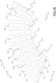
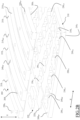
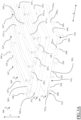
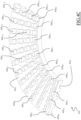
- FIG. 1A shows a perspective exploded view of a guide structure 100 for guiding chains along the forward section (thus referred to as forward guide structure hereinafter), according to an embodiment of the present invention.
- Figure 1A will be discussed jointly with Figures 1B , 1C and 1D , which show a perspective view, a close-up perspective partially-exploded view, and a sectional front view, respectively, of the forward guide structure 100.
- the longitudinal direction X corresponds, for each point of the curve, to the tangential component of the curve passing for that point (as also graphically represented in Figures 1A and 1B ) .
- the guide portion 105 and the base portion 110 are adapted to be fastened to each another, preferably in a reversible manner (as better discussed below).
- the guide portion 105 and the base portion 110 are preferably made of reciprocally different materials. More preferably, the guide portion 105 and the base portion 110 are made of materials having different characteristics of wear resistance and friction.
- the guide portion 105 is made of a material having a coefficient of friction lower than the coefficient of friction of the material of the base portion 110. Additionally or alternatively, the material of the guide portion 105 has a wear resistance higher than the wear resistance of the material of the base portion 110. According to an embodiment of the present invention, the material of the guide portion 105 comprises ultra-high-molecular-weight polyethylene (UHMWPE), also known as high-modulus polyethylene (HMPE) or high-performance polyethylene (HPPE), which ensures both low coefficient of friction and high wear resistance - in any case, other plastic materials may be used for the purpose.
- UHMWPE ultra-high-molecular-weight polyethylene
- HMPE high-modulus polyethylene
- HPPE high-performance polyethylene
- Figures 1E and 1F show bottom and top perspective views, respectively, of the guide portion 105 according to an embodiment of the present invention
- Figures 1G and 1H show top and bottom perspective views, respectively, of the base portion 110 according to an embodiment of the present invention.
- the guide portion 105 comprises a surface 105u that, in use, faces (and preferably contacts) the chains C h and is oriented upwards, thus referred to as upper surface hereinafter, and a surface 105 L , opposite the upper surface 105u, that, in use, faces the base portion 110 and is oriented downwards, thus referred to as lower surface hereinafter.
- five rails 115 1 -115 5 are provided, which delimit four guide channels 120 1 - 120 4 , the guide portion 105 thus identifying a multi-channel guide portion.
- the present invention is not limited to a specific number of guide channels - for example, the present invention equivalently applies to a guide portion formed as a single-channel guide portion for moving a single chain.
- the rails 115 1 -115 5 extend, along the longitudinal direction X, over the entire length of guide portion 105 (preferably, as illustrated, opening directly to its ends), and, along the transversal direction Z, parallel to each other (such that rails 115 1 -115 2 delimit the guide channel 120 1 , rails 115 2 -115 3 delimit the guide channel 120 2 , rails 115 3 -115 4 delimit the guide channel 120 3 , and rails 115 4 -115 5 delimit the guide channel 120 4 ). More preferably, the rails 115 1 -115 5 extend, along the transversal direction Z, parallel to each other at substantially same distances (such that the guide channels 120 1 -120 4 -have substantially same width).
- Each rail 115 comprises an upper wall 115 iw parallel to the upper surface 105u of the guide portion 105, and vertical side walls 115 i S1 , 115 i S2 extending, along the vertical direction Y, from opposite side ends of the respective upper wall 115 iw to the upper surface 105u, with each pair of vertical side walls 115 i S1 , 115 i S2 facing each other that delimit a respective guide channel 120 j (in the example at issue, the vertical side wall 115 1S2 of rail 115 1 and the vertical side wall 115 2S1 of rail 115 2 delimit the guide channel 120 1 , the vertical side wall 115 2S2 of rail 115 2 and the vertical side wall 115 3S1 of rail 115s delimit the guide channel 120 2 , the vertical side wall 115 3S2 of rail 115s and the vertical side wall 115 4S1 of rail 115 4 delimit the guide channel 120 3 , and the vertical side wall 115 4S2 of rail 115 4 and the vertical side wall
- all the vertical side walls 115 i S1 , 115 i S2 (and, hence, all the rails 115 i ) have substantially same extension in height ( i.e ., along the vertical direction ⁇ , the upper walls 115 iw thus identifying, as a whole, an uppermost surface of the guide portion 105 and the height of the vertical side walls 115 i S1 , 115 i S2 identifying a depth of the respective guide channels 120 j .
- the guide structure 100 preferably (although not necessarily) comprises magnetic interaction means adapted in use to magnetically interact with magnetic interaction means of the chain C h to cause a magnetic attraction of each chain C h within the respective guide channel 120 j ( i.e ., substantially along the vertical direction ⁇ .
- each guide channel 120 j is adapted to slidably receive within it the lower portion of the respective chain C h , with the upper walls 115 i W of the rails 115 i delimiting such guide channel 120 j (i.e., the uppermost surface 115 i w ) that face the chain C h and preferably form a slide abutment for an upper portion of the chain C h - as visible in Figure 1D .
- the magnetic interaction means of the forward guide structure 100 comprises one or more magnetic field generation elements (for example, electromagnets or, as herein assumed, permanent magnets - in the following, magnets) 125
- the magnetic interaction means of the chains C h comprises one or more elements of the chains C h (such as, just as an example, coupling pins intended to couple links of each chain C h to each other) made in ferritic steel or other ferromagnetic material so as to be responsive to the magnetic fields.
- the magnets 125 are arranged in the base portion 110, and, more preferably, run below each guide channel 120 j (so as to determine the magnetic attraction of each chain C h to the respective guide channel 120 j ).
- Each seat 130 j , n preferably extends from a surface 110 L of the base portion 110 that, in use is oriented downwards, thus referred to as lower surface hereinafter, towards (without opening to) a surface 110u that, in use, faces the lower surface 105 L of the guide portion 105 and is oriented upwards, thus referred to as upper surface hereinafter (the upper 110u and lower 110 L surfaces of the base portion 110 being thus opposite to each other).
- the seats 130 j , n are preferably formed by removal of material from the base portion 110 (for example by means of numerical control mechanical processing techniques). The seats 130 j, n are therefore accessible from below when the forward guide structure 100 is installed to the rest of the article conveyor.
- the same guide structure 100 acts as a shield, that is as an "umbrella", that avoids that liquid and slurry (for example, liquids used for periodic cleaning of the article conveyor, or slurry that may escape from the transported articles) penetrate into the seats 130 j , n thereby stagnating therein, thus making removal for hygienic reasons difficult and promoting instead the proliferation and spread of bacteria.
- liquid and slurry for example, liquids used for periodic cleaning of the article conveyor, or slurry that may escape from the transported articles
- the magnets 125 are accommodated within respective seats 130 j,n .
- the seats 130 j , n are preferably closable, from below, by respective lids or caps 135 j,n , for example removable lids or caps 135 j,n , which advantageously avoid both penetration of liquid and slurry into the seats 130 j , n and the fall by gravity of the magnets 125 from the respective seats 130 j , n when the forward guide structure 100 is in use.
- the magnets 125 are arranged in pairs, each pair of magnets 125 being for example accommodated within a respective seat 130 j,n .
- Each seat 130 j , n preferably comprises a median septum 133 j,n (shown in Figures 1C and 1E ) that essentially divides the respective seat 130 j,n in two parts (hereinafter, seat parts), with each magnet 125 of the pair that is preferably accommodated within a respective seat part.
- each lid 135 j,n is made of a ferromagnetic material, each pair of permanent magnets and the respective plate in ferromagnetic material defining a horseshoe magnet for increasing the magnetic attraction of the chains Cn into the respective channels 120 j - in any case, lids 135 j,n made of ferromagnetic material may also be associated with seats housing single magnets (instead of magnet pairs).
- Each lid 135 j,n is preferably fixed to the body of the base portion 110 by fixing means, such as one or more (preferably two) screws 140 screwed into threaded holes preferably formed in the septum 133 j,n .
- fixing means such as one or more (preferably two) screws 140 screwed into threaded holes preferably formed in the septum 133 j,n .
- the use of screws 140 for fixing the lids 135 j,n together with free accessibility thereof from below, makes assembly and disassembly operations feasible and easy.
- the forward guide structure 100 further comprises fastening means for fastening the guide portion 105 and the base portion 110 to each other at one or more rails 115i.
- the guide portion 105 and/or the base portion 110 comprises holes or through holes for the fitting of the fastening means, as discussed herebelow.
- the guide portion 105 preferably comprises one or more holes 145 GP , preferably a plurality of holes 145 GP , extending, along the vertical direction Y, into one or more of the rails 115 i (preferably, as illustrated, all the rails 115 i ), i.e. between the upper 105u and uppermost 115 i w surfaces of the guide portion 105, for allowing the guide portion 105 to be fastened to the base portion 110.
- fastening of the guide portion 105 to the base portion 110 is achieved by means of fastening means fitted into the holes 145 GP of the guide portion and into the base portion 110.
- the base portion 110 advantageously but not necessarily comprises one or more holes 145 BP , preferably a plurality of holes 145 GP , extending into the base portion 110 between the lower 110 L and upper 110u surfaces thereof.
- the holes 145 GP ,145 BP are arranged such that, upon superposition of the lower surface 105 L of the guide portion 105 with the upper surface 110u of the base portion 110, each hole 145 GP of the guide portion 105 matches a corresponding hole 145 BP of the base portion 110 thereby allowing fastening means to be received in the holes 145 GP of the guide portion 105 and in the holes hole 145 BP of the base portion 110 (thus allowing the guide portion 105 to be fastened to the base portion 110).
- the holes 145 GP of the guide portion 105 are through holes opening both to the upper walls 115 i w of the rails 115 i (or, equivalently, to the uppermost surface 115 i w of the guide portion 105) and to the lower surface 105 L of the guide portion 105), and the holes 145 BP of the base portion 110 are through holes opening to both upper 110 U and lower 110 L surfaces of the base portions.
- holes instead of through holes can be used in the guide portion 105 or in the base portion 110.
- through holes 145 GP in the guide portion 105 and holes in the base portion 110 might be envisaged when fastening from above is desired (in which case the holes in the base portion 110 would extend towards, without opening to, the lower surface 110 L thereof), or through holes 145 BP in the base portion 110 and holes in the guide portion 105 might be envisaged when fastening from below is desired (in which case the holes in the guide portion 105 would extend towards, without opening to, the upper wall 115 iw of the rails 115 i (or, equivalently, to the uppermost surface 115 iw of the guide portion 105).
- the fastening means comprises metric screws 150s adapted to be fitted into the through holes 145 GP of the guide portion 105 and coupled to threaded inserts 150 B fitted into the holes (or through holes) 145 BP of the base portion 110 - in any case, the metric screws 150s may also be fitted into holes or threaded holes of the base portion 110 and coupled to threaded inserts fitted into the holes (or through holes) of the guide portion 105 when, for example, fastening from below is desired.
- said threaded inserts 150 B comprise bushings, each bushing being for example threaded both externally (so as to allow firm anchoring of the bushing into the respective hole (or through hole) of the base portion 110 (or of the guide portion 105) and internally (so as to allow the metric screw 150s to be threaded in the bushing).
- the fastening means comprises self-tapping screws, in which case the holes or through holes 145 BP of the base portion 110 (fastening from above) or the holes or through holes 145 GP of the guide portion (fastening from below) may also be omitted (due to the capability of a self-tapping screw of tapping its own hole as it is driven into the material) or used as (or replaced by) aligning means for allowing easy and correct alignment between the guide portion 105 and the base portion 110.
- the fastening means may comprise, additionally to the metric screw/bushing pairs or to the self-tapping screws, a gasket or sealing and/or mastic or silicone layer at the interface between the guide 105 and base 110 portion ( i.e ., between the lower surface 105 L of the guide portion 105 and the upper surface 110u of the base portion 110), preferably at one or more side edges (such as a perimeter part) thereof, in order to provide additional protection against penetration of liquid and slurry into the seats 130 j,n .
- fastening between the guide portion 105 and the base portion 110 is achieved by fastening means fitted into the rails 115 i ( i . e ., passing through them either completely or partially) and, by arranging the respective holes, or through holes, 145 GP (when provided) in the rails 115 i .
- avoidance of the reinforcing members averts waste of material of the guide portion 105 (which is particularly beneficial when, as in the present invention, the material of the guide portion 105 is a relatively expensive material).
- FIG 2A shows a perspective exploded view of a guide structure 200 for guiding chains along the return section (thus referred to as return guide structure hereinafter), according to an embodiment of the present invention.
- the return guide structure 200 is shown upside down with respect to its orientation of use.
- Figure 2A will be discussed jointly with Figure 2B , which shows a close-up perspective exploded view of the return guide structure 200, with Figures 2C and 2D , which show bottom and top perspective views, respectively, of a base portion of the return guide structure 200, and Figure 2E , which shows a top perspective view of a guide portion of the return guide structure 200.
- the return guide structure 200 comprises a guide portion 205 for guiding the chains C h along the longitudinal direction X, and a base portion 210 for supporting (from above) the guide portion 205.
- the guide portion 205 and the base portion 210 are adapted to be fastened to each another, preferably in a reversible manner (as better discussed below).
- the guide portion 205 and the base portion 210 are preferably made of reciprocally different materials. More preferably, the guide portion 205 and the base portion 210 are made of materials having different characteristics of wear resistance and friction.
- the guide portion 205 is made of a material having a coefficient of friction lower than the coefficient of friction of the material of the base portion 210. Additionally or alternatively, the material of the guide portion 205 has a wear resistance higher than the wear resistance of the material of the base portion 210. According to an embodiment of the present invention, the material of guide portion 205 comprises ultra-high-molecular-weight polyethylene (UHMWPE), which ensures both low coefficient of friction and high wear resistance (in any case, other plastic materials may be used for the purpose), whereas the material of the base portion 210 is a low cost material (such as a conventional thermoplastic material) having no specific constrain on characteristics of wear resistance and/or friction.
- UHMWPE ultra-high-molecular-weight polyethylene
- the guide portion 205 comprises a surface 205 L that, in use, faces (and preferably contacts) the chains C h and is oriented downwards, thus referred to as lower surface hereinafter, and a surface 205u, opposite the lower surface 205 L , that, in use, faces the base portion 210 and is oriented upwards, thus referred to as upper surface hereinafter.
- five rails 215 1 -215 5 are provided, which delimit four guide channels 220 1 - 220 4 , the guide portion 205 thus identifying a multi-channel guide portion.
- the present invention is not limited to a specific number of guide channels - for example, the present invention equivalently applies to a guide portion formed as a single-channel guide portion for moving a single chain.
- the rails 215 1 -215 5 extend, along the longitudinal direction X, over the entire length of guide portion 205 (preferably, as illustrated, opening directly to its ends), and, along the transversal direction Z, parallel to each other (such that rails 215 1 -215 2 delimit the guide channel 220 1 , rails 215 2 -215 3 delimit the guide channel 220 2 , rails 215 3 -215 4 delimit the guide channel 220 3 , and rails 215 4 -215 5 delimit the guide channel 220 4 ). More preferably, the rails 215 1 -215 5 extend, along the transversal direction Z, parallel to each other at substantially same distances (such that the guide channels 220 1 -220 4 -have substantially same width).
- Each rail 215 comprises a lower wall 215 i w parallel to the lower surface 205 L of the guide portion 205, and vertical side walls 215 i S1 ,215 i S2 extending, along the vertical direction Y, from opposite side ends of the respective lower wall 215 i w to the lower surface 205 L , with each pair of vertical side walls 215 i S1 ,215 i S2 facing each other that delimit a respective guide channel 220 j (in the example at issue, the vertical side wall 215 1S2 of rail 215 1 and the vertical side wall 215 2S1 of rail 215 2 delimit the guide channel 220 1 , the vertical side wall 215 2S2 of rail 215 2 and the vertical side wall 215 3S1 of rail 215s delimit the guide channel 220 2 , the vertical side wall 215 3S2 of rail 215 3 and the vertical side wall 215 4S1 of rail 215 4 delimit the guide channel 220 3 , and the vertical side wall 215 4S2 of rail
- all the vertical side walls 215 i S1 ,215 i S2 (and, hence, all the rails 215 i ) have substantially same extension in height, the lower walls 215 i w thus identifying, as a whole, a lowermost surface of the guide portion 205 and the height of the vertical side walls 215 i S1 ,215 i S2 identifying a depth of the respective guide channels 220 j .
- the return guide structure 200 preferably comprises magnetic interaction means adapted in use to magnetically interact with magnetic interaction means of the chain C h to cause a magnetic attraction of each chain C h within the respective guide channel 220 j ( i.e ., substantially along the vertical direction ⁇ .
- each guide channel 220 j is adapted to slidably receive within it the lower portion of the respective chain C h , with the lower walls 215 i W of the rails 215 i delimiting such guide channel 220 j ( i.e ., the lowermost surface 215 i w ) that face the chain C h and preferably preferably form a slide abutment for an upper portion of the chain C h .
- the magnetic interaction means of the return guide structure 200 comprises one or more magnetic field generation elements (for example, electromagnets or, as herein assumed, permanent magnets - in the following, magnets) 225
- the magnetic interaction means of the chains C h comprises one or more elements of the chains C h (such as, just as an example, coupling pins intended to couple links of each chain C h to each other) made in ferritic steel or other ferromagnetic material so as to be responsive to the magnetic fields.
- the magnets 225 are arranged in the base portion 210, and, more preferably, run below each guide channel 220 j (so as to determine the magnetic attraction of each chain C h to the respective guide channel 220 j ).
- Each seat 230 j,n preferably extends from a surface 210 L of the base portion 210 that, in use is oriented downwards and faces the guide portion 205 ( i.e ., the upper surface 205u thereof), thus referred to as lower surface hereinafter, towards (without opening to) a surface 210u that, in use, is oriented upwards, thus referred to as upper surface hereinafter (the upper 210u and lower 210 L surfaces of the base portion 210 being thus opposite to each other).
- the seats 230 j,n are preferably formed by removal of material from the base portion 210 (for example by means of numerical control mechanical processing techniques). The seats 230 j,n are therefore accessible from below when the return guide structure 200 is installed to the rest of the article conveyor.
- the guide 205 and base 210 portions act themselves as shields that avoid that liquid and slurry (for example, liquids used for periodic cleaning of the article conveyor, or slurry that may escape from the transported articles) penetrate into the seats 230 j,n from above and from below, respectively, thereby stagnating therein and making removal for hygienic reasons difficult.
- liquid and slurry for example, liquids used for periodic cleaning of the article conveyor, or slurry that may escape from the transported articles
- lids for the seats 230 j,n are required for the embodiment of return guide structure 200 herein discussed, in that the function avoiding penetration of liquid and slurry and the fall by gravity of the magnets 225 is carried out by the guide portion 205 - however, the presence of lids may be envisaged when forming seats extending from (and opening to) the upper surface 210u of the base portion 210 towards (without opening to) the lower surface 210 L .
- each pair of magnets 225 is magnetically coupled to a plate 225 P in ferromagnetic material, preferably space apart from each other. In this way, each pair of magnets 225 and the respective plate 225 P in ferromagnetic material define a horseshoe magnet.
- the return guide structure 200 further comprises fastening means for fastening the guide portion 205 and the base portion 210 to each other at one or more rails 215;.
- the guide portion 205 and/or the base portion 210 comprises holes or through holes for the fitting of the fastening means, as discussed herebelow.
- the guide portion 205 preferably comprises one or more holes 245 GP , preferably a plurality of holes 245 GP , extending, along the vertical direction Y, into one or more of the rails 215; (preferably, as illustrated, all the rails 215 i ), i.e . between the lower 205 L and lowermost 215 i W surfaces of the guide portion 205, for allowing the guide portion 205 to be fastened to the base portion 210.
- fastening of the guide portion 205 to the base portion 110 is preferably achieved by means of fastening means fitted into the holes 245 GP of the guide portion and into the base portion 210.
- the base portion 210 advantageously but not necessarily comprises one or more holes 245 BP , preferably a plurality of holes 245 GP , extending into the base portion 210 between the lower 210 L and upper 210u surfaces thereof.
- the holes 245 GP ,245 BP are arranged such that, upon superposition of the upper surface 205u of the guide portion 205 with the lower surface 210 L of the base portion 210, each hole 245 GP of the guide portion 205 matches a corresponding hole 245 BP of the base portion 110 thereby allowing fastening means to be received in the holes 245 GP of the guide portion 205 and in the holes hole 245 BP of the base portion 210 (thus allowing the guide portion 205 to be fastened to the base portion 210).
- the holes 245 GP of the guide portion 205 are through holes opening both to the lower walls 215 i w of the rails 215 i (or, equivalently, to the lowermost surface 205 i W of the guide portion 205) and to the upper surface 205u of the guide portion 205), as visible in Figures 2B and 2E .
- the holes 245 BP of the base portion 210 may for example be through holes opening to both upper 210u and lower 210 L surfaces of the base portion 210, or, as exemplary illustrated in Figures 2C and 2D , holes opening only to the lower surface 210 L of the base portion 210 (the upper surface 210u of the base portion 210 being thus flat and free from machining).
- holes instead of through holes can be used in the guide portion 205, and/or through holes instead of holes can be used in the base portion 210.
- the fastening means comprises metric screws 250 S adapted to be fitted into through holes of the guide portion 205 and coupled to threaded inserts (e.g ., externally and/or internally threaded bushings), not visible in the figures, fitted into the holes (or through holes) of the base portion 210 - in any case, the metric screws 250 S may also be fitted into holes or threaded holes of the base portion 210 and coupled to threaded inserts fitted into the holes (or through holes) of the guide portion 205 when, for example, fastening from above is desired.
- threaded inserts e.g ., externally and/or internally threaded bushings
- the fastening means comprises self-tapping screws, not shown, in which case the holes or through holes 245 BP of the base portion 210 (fastening from below) or the holes or through holes 245 GP of the guide portion 205 (fastening from above) may also be omitted (due to the capability of a self-tapping screw of tapping its own hole as it is driven into the material) or used as (or replaced by) aligning means for allowing easy and correct alignment between the guide portion 205 and the base portion 210.
- fastening between the guide portion 205 and the base portion 210 is achieved by fastening means fitted into the rails 215 i ( i . e ., passing through them either completely or partially), and by arranging the respective holes, or through holes, 245 GP (when provided) in the rails 215 i .
- the fastening means may comprise, additionally to the metric screw/bushing pairs or to the self-tapping screws, a gasket or sealing and/or mastic or silicone layer at the interface between the guide 205 and base 210 portion ( i . e ., between the upper surface 205u of the guide portion 205 and the lower surface 210 L of the base portion 210), preferably at one or more side edges (such as a perimeter part) thereof, in order to provide additional protection against penetration of liquid and slurry into the seats 230 j,n .
- the absence of teeth or of other reinforcing members in the guide structure 200 results in a flat ( i . e ., planar) surface of the upper surface 205u of the guide portion 205, such that positioning and machining are advantageously performed at a single side only ( i . e . at the lower surface 205 L of the guide portion 205).
- Figure 3A shows a perspective partly exploded view of a forward and return guide structure 300 according to an embodiment of the present invention.
- Figures 3B and 3C show a perspective exploded view and a perspective sectional view, respectively, of the forward and return guide structure 300
- Figure 3D shows a perspective view of a base portion of the forward and return guide structure 300.
- the forward and return guide structure 300 comprises a guide portion 305, a further guide portion 305', and a base portion 310 between the guide portion 305 and the further guide portion 305' along the vertical direction Y.
- the guide portion 305 and the further guide portion 305' of the forward and return guide structure 300 are equivalent to the guide portion 205 of the return guide structure 200 and to the guide portion 105 of the forward guide structure 100, respectively, and the base portion 310 of the forward and return guide structure 300 is similar to the base portion 210 of the return guide structure 200.
- the guide portion 305 is fastened to the base portion 310 (with the lower surface 310 L of the base portion 310 that faces the upper surface 305u of the guide portion 305), preferably by fastening means comprising, for example, metric screws 350s adapted to be fitted into through holes 345 GP of the guide portion 305, and threaded inserts ( e . g ., internally and, preferably, externally threaded bushings), not visible in the figures, fitted into the holes 345 BP of the base portion 310 for being coupled to the metric screws 350 S .
- fastening means comprising, for example, metric screws 350s adapted to be fitted into through holes 345 GP of the guide portion 305, and threaded inserts ( e . g ., internally and, preferably, externally threaded bushings), not visible in the figures, fitted into the holes 345 BP of the base portion 310 for being coupled to the metric screws 350 S .
- the further guide portion 305' is fastened to the base portion 310 (with the upper surface 310u of the base portion 310 that faces the lower surface 305' L of the further guide portion 305'), preferably by fastening means comprising, for example, metric screws 350's adapted to be fitted into through holes 345' GP of the further guide portion 305', and threaded inserts ( e . g ., internally and, preferably, externally threaded bushings), shown in Figure 3B , fitted into the holes 345' BP of the base portion 310 for being coupled to the metric screws 350's.
- fastening means comprising, for example, metric screws 350's adapted to be fitted into through holes 345' GP of the further guide portion 305', and threaded inserts ( e . g ., internally and, preferably, externally threaded bushings), shown in Figure 3B , fitted into the holes 345' BP of the base portion 310 for being coupled to the metric
- the holes 345 BP opening to the lower surface 305 L of the base portion 310 (and, hence, the through holes 345 GP of the guide portion 305) and the holes 345' BP opening to the upper surface 305'u of the base portion 310 (and, hence, the through holes 345' GP of the further guide portion 305') are staggered to each other, preferably, as illustrated, along the longitudinal direction X ( i . e ., along the rails 315 i ,315' i . ).
- each seat 330 j,n accommodates four magnets. More preferably, each seat 330 j,n accommodates two pairs of magnets, namely a pair of magnets 325 for attracting the chains C H downwards in the guide portion 305 (forward path) and a pair of magnets 325' for attracting the chains C H upwards in the further guide portion 305' (forward path). Even more preferably, each pair of magnets 325,325' is magnetically coupled to a plate 325 P in ferromagnetic material, preferably from opposite ( e . g ., top and bottom) sides thereof. In this way, each pair of magnets 325,325' and the respective plate 325 P in ferromagnetic material define two horseshoe magnets accommodated in a same seat 330 j,n .
- Figures 4A and 4B show a perspective view and a perspective exploded view, respectively, of a forward and return guide structure 400 according to another embodiment of the present invention.
- Figure 4C shows a perspective view of a base portion of the forward and return guide structure 400
- Figure 4D shows a perspective sectional view of the forward and return guide structure 400.
- the forward and return guide structure 400 comprises a guide portion 405 and a base portion 410.
- the guide portion 405 of the forward and return guide structure 400 is for example equivalent to the guide portion 105 of the forward guide structure 100, whereas the base portion 410 of the forward and return guide structure 400 is similar to the base portion 210 of the return guide structure 200.
- the guide portion 405 is fastened to the base portion 410 (with the upper surface 410u of the base portion 410 that faces the lower surface 405 L of the guide portion 405), preferably by fastening means comprising, for example, metric screws 450s adapted to be fitted into the through holes 445 GP of the guide portion 405, and threaded inserts ( e . g ., externally and/or internally threaded bushings) 445 B , fitted into the holes 445 BP of the base portion 410 for being coupled to the metric screws 450s.
- fastening means comprising, for example, metric screws 450s adapted to be fitted into the through holes 445 GP of the guide portion 405, and threaded inserts ( e . g ., externally and/or internally threaded bushings) 445 B , fitted into the holes 445 BP of the base portion 410 for being coupled to the metric screws 450s.
- each rail 415' i extends, along the vertical direction Y, from the lower surface 410 L of the base portion 410 to a lowermost surface 415' i W of the base portion 410, and each pair of rails 415'; delimits, along the transversal direction Z, a respective guide channel 420' j .
- each seat 430 j,n advantageously extends from the upper surface 410u of the base portion 410 towards the lower surface 410 L of the base portion 410 in order to be accessible form above (since the guide portion 405 is, in this embodiment, the only removable component).
- each seat 430 j,n accommodates four magnets. More preferably, each seat 430 j,n accommodates two pairs of magnets, namely a pair of magnets 425 for attracting the chains C H downwards in the guide portion 405 (forward path) and a pair of magnets 425' for attracting the chains C H upwards in the guide channels 420' j (return path). Even more preferably, each pair of magnets 425,425' is magnetically coupled to a plate 425 P in ferromagnetic material, preferably from opposite ( e.g ., top and bottom) sides thereof. In this way, each pair of magnets 425,425' and the respective plate 425 P in ferromagnetic material define two horseshoe magnets accommodated in a same seat 430 j,n .
Landscapes
- Engineering & Computer Science (AREA)
- Mechanical Engineering (AREA)
- Devices For Conveying Motion By Means Of Endless Flexible Members (AREA)
- Chain Conveyers (AREA)
Claims (12)
- Führungsstruktur (100; 200; 300; 400) für eine Kette (C h ) für einen Artikelförderer, wobei die Führungsstruktur Folgendes umfasst:einen Führungsabschnitt (105; 205; 305; 405) zum Führen der Kette entlang einer ersten Richtung (X), die eine Bewegungsrichtung der Kette angibt, wobei der Führungsabschnitt eine erste Oberfläche des Führungsabschnitts (105u; 205L; 305L; 305U; 405u), die im Gebrauch der Kette zugewandt ist, und eine zweite Oberfläche des Führungsabschnitts (105L; 205U; 305U; 305'L; 405L) gegenüber der ersten Oberfläche des Führungsabschnitts aufweist, und wobei der Führungsabschnitt mindestens zwei Schienen (115 i ; 215 i ; 315 i ; 415' i ) umfasst, die sich jeweils entlang einer zweiten Richtung (Y) orthogonal zu der ersten Richtung von der ersten Oberfläche des Führungsabschnitts zu einer dritten Oberfläche (115 iW; 215 iW; 315 iW; 415 iW) des Führungsabschnitts erstrecken, die im Gebrauch der Kette zugewandt ist, wobei jedes Schienenpaar entlang einer dritten Richtung (Z) orthogonal zu den ersten und zweiten Richtungen einen jeweiligen Führungskanal (120 j ; 220 j ; 320 j ; 420 j ) zur zumindest teilweisen Aufnahme der Kette begrenzt, wobei jeder Führungskanal Seitenwände aufweist, die von Seitenwänden (115 iS1, 115 iS2; 215 iS1, 215 iS2; 315 iS1, 315 iS2; 415 iS1, 415 iS2) des Schienenpaares und einer Bodenwand gebildet werden, die die erste Oberfläche bildet, undeinen Basisabschnitt (110; 210; 310; 410) zum Tragen des Führungsabschnitts, wobei der Basisabschnitt eine erste Oberfläche des Basisabschnitts (110u; 210L; 310L; 410U), die im Gebrauch der zweiten Oberfläche des Führungsabschnitts zugewandt ist, und eine zweite Oberfläche des Basisabschnitts (110L; 210U; 310U; 410L) gegenüber der ersten Oberfläche des Basisabschnitts aufweist, wobei der Basisabschnitt aus einem ersten Material hergestellt ist und der Führungsabschnitt aus einem zweiten Material hergestellt ist, das sich von dem ersten Material unterscheidet, wobei die Führungsstruktur weiter Befestigungsmittel (150S,150B; 250S,250B; 350S,350B; 450S,450B;) umfasst, um den Führungsabschnitt und den Basisabschnitt an einer oder mehreren der mindestens zwei Schienen aneinander zu befestigen, dadurch gekennzeichnet, dass der Führungsabschnitt Löcher (145GP; 245GP; 345GP; 445GP) umfasst, die sich entlang der zweiten Richtung in die Schienen zwischen der ersten und der dritten Oberfläche des Führungsabschnitts erstrecken, und wobei das Befestigungsmittel dazu angepasst ist, in die Löcher und in den Basisabschnitt eingebaut zu werden, um zu ermöglichen, dass der Führungsabschnitt an dem Basisabschnitt befestigt wird, und dadurch, dass die Löcher des Führungsabschnitts Durchgangslöcher umfassen, die sich sowohl zu der ersten als auch zu der dritten Oberfläche des Führungsabschnitts öffnen.
- Führungsstruktur (100; 200; 300; 400) nach Anspruch 1, wobei der Basisabschnitt Löcher (145BP; 245BP; 345BP; 445BP) umfasst, die sich in den Basisabschnitt zwischen der ersten und der zweiten Oberfläche des Basisabschnitts erstrecken, wobei beim Übereinanderlegen der zweiten Oberfläche des Führungsabschnitts auf die erste Oberfläche des Basisabschnitts die Löcher des Führungsabschnitts mit den jeweiligen Löchern des Basisabschnitts übereinstimmen, wobei die Befestigungsmittel dazu angepasst sind, weiter in die Löcher des Basisabschnitts eingebaut zu werden, um zu ermöglichen, dass der Führungsabschnitt an dem Basisabschnitt befestigt wird.
- Führungsstruktur (100; 200; 300; 400) nach Anspruch 1 oder 2 in Abhängigkeit von Anspruch 3, wobei die Löcher des Basisabschnitts Durchgangslöcher umfassen, die sich sowohl zu der ersten als auch zu der zweiten Oberfläche des Basisabschnitts öffnen.
- Führungsstruktur (100; 200; 300; 400) nach einem der vorstehenden Ansprüche, wobei der Basisabschnitt mindestens einen Sitz (130 j,n ; 230 j,n ; 330 j,n ; 430 j,n ) zur Aufnahme von magnetischen Wechselwirkungsmitteln (125; 225; 325,325'; 425,425') der Führungsstruktur umfasst, die im Gebrauch dazu angepasst sind, mit magnetischen Wechselwirkungsmitteln der Kette magnetisch zu wechselwirken, um eine magnetische Anziehung der Kette zur Führungsstruktur zu bewirken.
- Führungsstruktur (200) nach Anspruch 4, wobei die Führungsstruktur eine Rücklaufführungsstruktur zum Führen der Kette entlang mindestens eines Abschnitts eines Rücklaufabschnitts des Förderwegs des Artikelförderers ist, und wobei sich der mindestens eine Sitz (230 j,n ) von der ersten Oberfläche (210L) des Basisabschnitts in Richtung der zweiten Oberfläche (210u) des Basisabschnitts erstreckt, und wobei beim Befestigen des Führungsabschnitts an dem Basisabschnitt der Führungsabschnitt den mindestens einen Sitz abdeckt, wodurch verhindert wird, dass Flüssigkeiten, Schlamm und Schmutz mit den darin untergebrachten magnetischen Wechselwirkungsmitteln in Kontakt kommen.
- Führungsstruktur (200) nach Anspruch 5, wobei das magnetische Wechselwirkungsmittel der Führungsstruktur mindestens ein Paar von Permanentmagneten (225) umfasst, die magnetisch mit einer Platte (225p) aus ferromagnetischem Material gekoppelt sind, wobei jedes Paar von Permanentmagneten und die jeweilige Platte aus ferromagnetischem Material einen Hufeisenmagneten definieren.
- Führungsstruktur (100) nach Anspruch 4, wobei die Führungsstruktur eine Vorwärtsführungsstruktur zum Führen der Kette entlang mindestens eines Abschnitts eines Vorlaufabschnitts des Förderweges des Artikelförderers ist, und wobei sich der mindestens eine Sitz von der zweiten Oberfläche (110L) des Bodenabschnitts zu der ersten Oberfläche (110u) des Bodenabschnitts erstreckt, wobei die Führungsstruktur weiter mindestens einen Deckel (135 j,n ), vorzugsweise einen abnehmbaren Deckel, zum Verschließen des mindestens einen Sitzes umfasst, wodurch verhindert wird, dass Flüssigkeiten, Schlamm und Schmutz mit den darin untergebrachten magnetischen Wechselwirkungsmitteln in Kontakt kommen und die darin untergebrachten magnetischen Wechselwirkungsmittel herunterfallen.
- Führungsstruktur (100) nach Anspruch 7, wobei das magnetische Wechselwirkungsmittel der Führungsstruktur mindestens ein Paar Permanentmagnete (125) umfasst, und wobei der Deckel aus ferromagnetischem Material hergestellt ist, wobei jedes Paar Permanentmagnete und der Deckel aus ferromagnetischem Material einen Hufeisenmagneten definieren.
- Führungsstruktur (300) nach einem der vorstehenden Ansprüche,wobei die Führungsstruktur weiter einen weiteren Führungsabschnitt (305') umfasst, der vorzugsweise aus dem zweiten Material hergestellt ist und eine erste Oberfläche (305'u) des weiteren Führungsabschnitts aufweist, die im Gebrauch der Kette zugewandt ist, sowie eine zweite Oberfläche (305'L) des weiteren Führungsabschnitts, die der ersten Oberfläche des weiteren Führungsabschnitts gegenüberliegt, wobei der weitere Führungsabschnitt mindestens zwei Schienen (315' i ) umfasst, die sich jeweils entlang der zweiten Richtung von der ersten Oberfläche des weiteren Führungsabschnitts zu einer dritten Oberfläche (315'iw) des weiteren Führungsabschnitts erstrecken, die im Gebrauch der Kette zugewandt ist, und wobei jedes Paar von Schienen entlang der dritten Richtung einen jeweiligen Führungskanal (320 j ) zur zumindest teilweisen Aufnahme der Kette begrenzt,wobei der Basisabschnitt auch zum Tragen des weiteren Führungsabschnitts angeordnet ist, wobei die zweite Oberfläche des Basisabschnitts im Gebrauch der zweiten Oberfläche des weiteren Führungsabschnitts gegenüberliegt,und wobei die Führungsstruktur weitere Befestigungsmittel (350's, 350'B) zum Befestigen des weiteren Führungsabschnitts und des Basisabschnitts aneinander an den mindestens zwei Schienen des weiteren Führungsabschnitts umfasst.
- Führungsstruktur (400) nach einem der Ansprüche 1 bis 8,wobei der Basisabschnitt mindestens zwei weitere Schienen (415' i ) umfasst, die sich jeweils entlang der zweiten Richtung von der zweiten Oberfläche des Basisabschnitts zu einer dritten Oberfläche (415'iw) des Basisabschnitts erstrecken, wobei jedes Paar von Schienen entlang der dritten Richtung einen jeweiligen Führungskanal (420' j ) zur zumindest teilweisen Aufnahme der Kette begrenzt,wobei die mindestens zwei weiteren Schienen in einem einzigen Stück mit dem Basisabschnitt ausgebildet sind,und wobei die Befestigungsmittel den Führungsabschnitt und den Basisabschnitt an den mindestens zwei Schienen des Führungsabschnitts und an den mindestens zwei weiteren Schienen des Basisabschnitts aneinander befestigen.
- Führungsstruktur (100; 200; 300; 400) nach einem der vorstehenden Ansprüche, wobei das zweite Material einen niedrigeren Reibungskoeffizienten als der Reibungskoeffizient des ersten Materials und/oder eine höhere Verschleißfestigkeit als die Verschleißfestigkeit des ersten Materials aufweist.
- Führungsstruktur (100; 200; 300; 400) nach einem der vorstehenden Ansprüche, wobei die zweite Oberfläche des Führungsabschnitts (105L; 205u; 305u; 305'L; 405L) eine ebene Oberfläche ist.
Applications Claiming Priority (2)
| Application Number | Priority Date | Filing Date | Title |
|---|---|---|---|
| IT102017000030510A IT201700030510A1 (it) | 2017-03-20 | 2017-03-20 | Struttura di guida per catena per trasportatore di articoli |
| PCT/EP2018/056901 WO2018172290A1 (en) | 2017-03-20 | 2018-03-19 | Guide structure for chain for article conveyor |
Publications (3)
| Publication Number | Publication Date |
|---|---|
| EP3601115A1 EP3601115A1 (de) | 2020-02-05 |
| EP3601115C0 EP3601115C0 (de) | 2024-11-06 |
| EP3601115B1 true EP3601115B1 (de) | 2024-11-06 |
Family
ID=59381624
Family Applications (1)
| Application Number | Title | Priority Date | Filing Date |
|---|---|---|---|
| EP18711347.7A Active EP3601115B1 (de) | 2017-03-20 | 2018-03-19 | Führungsstruktur für kette für artikelförderer |
Country Status (4)
| Country | Link |
|---|---|
| EP (1) | EP3601115B1 (de) |
| CN (1) | CN110382377A (de) |
| IT (1) | IT201700030510A1 (de) |
| WO (1) | WO2018172290A1 (de) |
Families Citing this family (2)
| Publication number | Priority date | Publication date | Assignee | Title |
|---|---|---|---|---|
| IT202100019175A1 (it) | 2021-07-20 | 2023-01-20 | Movex S P A | Elemento di contenimento per magneti atto ad essere associato ad una struttura di supporto e guida magnetica |
| IT202300011184A1 (it) * | 2023-06-01 | 2024-12-01 | Movex S P A | Elemento di contenimento a tenuta per i magneti di una struttura magnetica di supporto e di guida per dispositivi trasportatori a maglie articolate |
Family Cites Families (10)
| Publication number | Priority date | Publication date | Assignee | Title |
|---|---|---|---|---|
| US5732814A (en) * | 1996-12-04 | 1998-03-31 | Mannesmann Dematic Rapistan Corp. | Method and apparatus for reducing noise and wear in a conveyor transition section |
| IT237914Y1 (it) * | 1997-09-18 | 2000-09-29 | Regina Sud Spa | Guida magnetica migliorata |
| IT1296436B1 (it) * | 1997-11-14 | 1999-06-25 | System Plast Snc Marsetti & C | Un elemento curvo per un trasportatore magnetico a catena ed un trasportatore comprendente detto elemento |
| CN2320592Y (zh) * | 1997-11-28 | 1999-05-26 | 王兴旺 | 生产线链条输送机铝挤型轨道 |
| CN200946040Y (zh) * | 2006-09-07 | 2007-09-12 | 上海德马物流技术有限公司 | 链条输送机 |
| CN201169456Y (zh) * | 2008-01-23 | 2008-12-24 | 东莞丰裕电机有限公司 | 输送轨道 |
| CN102837933A (zh) * | 2012-09-07 | 2012-12-26 | 西安船舶工程研究院有限公司 | 重介质浅槽分选机 |
| CN103144935B (zh) * | 2013-03-20 | 2016-04-13 | 承德华远自动化设备有限公司 | 一种等速变倍速输送机 |
| CN203319157U (zh) * | 2013-05-29 | 2013-12-04 | 邱俊民 | 铝挤型输送链条轨道 |
| WO2016131879A1 (en) * | 2015-02-18 | 2016-08-25 | Rexnord Flattop Europe S.R.L. | Guide for chain for articles conveyor |
-
2017
- 2017-03-20 IT IT102017000030510A patent/IT201700030510A1/it unknown
-
2018
- 2018-03-19 EP EP18711347.7A patent/EP3601115B1/de active Active
- 2018-03-19 CN CN201880015326.8A patent/CN110382377A/zh active Pending
- 2018-03-19 WO PCT/EP2018/056901 patent/WO2018172290A1/en not_active Ceased
Also Published As
| Publication number | Publication date |
|---|---|
| CN110382377A (zh) | 2019-10-25 |
| WO2018172290A1 (en) | 2018-09-27 |
| EP3601115A1 (de) | 2020-02-05 |
| IT201700030510A1 (it) | 2018-09-20 |
| EP3601115C0 (de) | 2024-11-06 |
Similar Documents
| Publication | Publication Date | Title |
|---|---|---|
| US10093486B2 (en) | Guide for chain for articles conveyor | |
| EP3601115B1 (de) | Führungsstruktur für kette für artikelförderer | |
| JP6512127B2 (ja) | 物品搬送装置及びそれを備えた物品搬送設備 | |
| EP2055655A1 (de) | Fahrrahmenvorrichtung für eine fördereinrichtung | |
| US20150245761A1 (en) | Tray supporting apparatus for dishwasher, cutlery tray assembly and dishwasher | |
| KR101953910B1 (ko) | 슬라이딩 창호용 분리 착탈 가능한 세그먼트 구조의 도어 가이드 프레임 | |
| EP2907774A1 (de) | Führungsschiene für Plattengliederkette | |
| US20060081447A1 (en) | Guide particularly for conveyor belts | |
| ITMI970668U1 (it) | Guida magnetica migliorata | |
| CN102076246A (zh) | 壁元件 | |
| US5782340A (en) | Tapered side support for conveyor belts | |
| DE60302970D1 (de) | Förderbandmodul mit einer Reibungsoberfäche | |
| US11034520B2 (en) | Modular structure curved magnetic guide for guiding the chain of a conveyor chain | |
| EP3964458B1 (de) | Tragstruktur mit verbesserter steifigkeit für einen gelenkigen gliederförderer | |
| WO2016116310A1 (en) | Sliding guide shoe for an elevator | |
| KR101864703B1 (ko) | 부품 이송용 팔레트 | |
| AU5655499A (en) | Conveyor mat built up from plastic modules, and module for such conveyor mat | |
| US20050000180A1 (en) | Decoration panel | |
| AU2009205831B2 (en) | Return guide bend segment | |
| JP6580952B2 (ja) | 間仕切り収納ユニット | |
| KR20100006572U (ko) | 컨베이어 프레임 | |
| FI118221B (fi) | Hissin ovijärjestely | |
| IT202100003740U1 (it) | Struttura magnetica di supporto e guida | |
| IT201800010556A1 (it) | Dispositivo di supporto e fissaggio a pavimento di una balaustra in vetro | |
| KR20220150941A (ko) | 수직 가이드 채널 |
Legal Events
| Date | Code | Title | Description |
|---|---|---|---|
| STAA | Information on the status of an ep patent application or granted ep patent |
Free format text: STATUS: UNKNOWN |
|
| STAA | Information on the status of an ep patent application or granted ep patent |
Free format text: STATUS: THE INTERNATIONAL PUBLICATION HAS BEEN MADE |
|
| PUAI | Public reference made under article 153(3) epc to a published international application that has entered the european phase |
Free format text: ORIGINAL CODE: 0009012 |
|
| STAA | Information on the status of an ep patent application or granted ep patent |
Free format text: STATUS: REQUEST FOR EXAMINATION WAS MADE |
|
| 17P | Request for examination filed |
Effective date: 20191003 |
|
| AK | Designated contracting states |
Kind code of ref document: A1 Designated state(s): AL AT BE BG CH CY CZ DE DK EE ES FI FR GB GR HR HU IE IS IT LI LT LU LV MC MK MT NL NO PL PT RO RS SE SI SK SM TR |
|
| AX | Request for extension of the european patent |
Extension state: BA ME |
|
| DAV | Request for validation of the european patent (deleted) | ||
| DAX | Request for extension of the european patent (deleted) | ||
| STAA | Information on the status of an ep patent application or granted ep patent |
Free format text: STATUS: EXAMINATION IS IN PROGRESS |
|
| 17Q | First examination report despatched |
Effective date: 20220705 |
|
| P01 | Opt-out of the competence of the unified patent court (upc) registered |
Effective date: 20230522 |
|
| GRAP | Despatch of communication of intention to grant a patent |
Free format text: ORIGINAL CODE: EPIDOSNIGR1 |
|
| STAA | Information on the status of an ep patent application or granted ep patent |
Free format text: STATUS: GRANT OF PATENT IS INTENDED |
|
| INTG | Intention to grant announced |
Effective date: 20240607 |
|
| GRAS | Grant fee paid |
Free format text: ORIGINAL CODE: EPIDOSNIGR3 |
|
| GRAA | (expected) grant |
Free format text: ORIGINAL CODE: 0009210 |
|
| STAA | Information on the status of an ep patent application or granted ep patent |
Free format text: STATUS: THE PATENT HAS BEEN GRANTED |
|
| AK | Designated contracting states |
Kind code of ref document: B1 Designated state(s): AL AT BE BG CH CY CZ DE DK EE ES FI FR GB GR HR HU IE IS IT LI LT LU LV MC MK MT NL NO PL PT RO RS SE SI SK SM TR |
|
| REG | Reference to a national code |
Ref country code: GB Ref legal event code: FG4D |
|
| REG | Reference to a national code |
Ref country code: CH Ref legal event code: EP |
|
| REG | Reference to a national code |
Ref country code: DE Ref legal event code: R096 Ref document number: 602018076225 Country of ref document: DE |
|
| REG | Reference to a national code |
Ref country code: IE Ref legal event code: FG4D |
|
| U01 | Request for unitary effect filed |
Effective date: 20241114 |
|
| P04 | Withdrawal of opt-out of the competence of the unified patent court (upc) registered |
Free format text: CASE NUMBER: APP_61698/2024 Effective date: 20241118 |
|
| U07 | Unitary effect registered |
Designated state(s): AT BE BG DE DK EE FI FR IT LT LU LV MT NL PT RO SE SI Effective date: 20241121 |
|
| U20 | Renewal fee for the european patent with unitary effect paid |
Year of fee payment: 8 Effective date: 20250211 |
|
| PG25 | Lapsed in a contracting state [announced via postgrant information from national office to epo] |
Ref country code: HR Free format text: LAPSE BECAUSE OF FAILURE TO SUBMIT A TRANSLATION OF THE DESCRIPTION OR TO PAY THE FEE WITHIN THE PRESCRIBED TIME-LIMIT Effective date: 20241106 Ref country code: IS Free format text: LAPSE BECAUSE OF FAILURE TO SUBMIT A TRANSLATION OF THE DESCRIPTION OR TO PAY THE FEE WITHIN THE PRESCRIBED TIME-LIMIT Effective date: 20250306 |
|
| PG25 | Lapsed in a contracting state [announced via postgrant information from national office to epo] |
Ref country code: ES Free format text: LAPSE BECAUSE OF FAILURE TO SUBMIT A TRANSLATION OF THE DESCRIPTION OR TO PAY THE FEE WITHIN THE PRESCRIBED TIME-LIMIT Effective date: 20241106 |
|
| PG25 | Lapsed in a contracting state [announced via postgrant information from national office to epo] |
Ref country code: NO Free format text: LAPSE BECAUSE OF FAILURE TO SUBMIT A TRANSLATION OF THE DESCRIPTION OR TO PAY THE FEE WITHIN THE PRESCRIBED TIME-LIMIT Effective date: 20250206 |
|
| PG25 | Lapsed in a contracting state [announced via postgrant information from national office to epo] |
Ref country code: GR Free format text: LAPSE BECAUSE OF FAILURE TO SUBMIT A TRANSLATION OF THE DESCRIPTION OR TO PAY THE FEE WITHIN THE PRESCRIBED TIME-LIMIT Effective date: 20250207 |
|
| PG25 | Lapsed in a contracting state [announced via postgrant information from national office to epo] |
Ref country code: PL Free format text: LAPSE BECAUSE OF FAILURE TO SUBMIT A TRANSLATION OF THE DESCRIPTION OR TO PAY THE FEE WITHIN THE PRESCRIBED TIME-LIMIT Effective date: 20241106 |
|
| PG25 | Lapsed in a contracting state [announced via postgrant information from national office to epo] |
Ref country code: RS Free format text: LAPSE BECAUSE OF FAILURE TO SUBMIT A TRANSLATION OF THE DESCRIPTION OR TO PAY THE FEE WITHIN THE PRESCRIBED TIME-LIMIT Effective date: 20250206 |
|
| PG25 | Lapsed in a contracting state [announced via postgrant information from national office to epo] |
Ref country code: SM Free format text: LAPSE BECAUSE OF FAILURE TO SUBMIT A TRANSLATION OF THE DESCRIPTION OR TO PAY THE FEE WITHIN THE PRESCRIBED TIME-LIMIT Effective date: 20241106 |
|
| PG25 | Lapsed in a contracting state [announced via postgrant information from national office to epo] |
Ref country code: SK Free format text: LAPSE BECAUSE OF FAILURE TO SUBMIT A TRANSLATION OF THE DESCRIPTION OR TO PAY THE FEE WITHIN THE PRESCRIBED TIME-LIMIT Effective date: 20241106 |
|
| PG25 | Lapsed in a contracting state [announced via postgrant information from national office to epo] |
Ref country code: CZ Free format text: LAPSE BECAUSE OF FAILURE TO SUBMIT A TRANSLATION OF THE DESCRIPTION OR TO PAY THE FEE WITHIN THE PRESCRIBED TIME-LIMIT Effective date: 20241106 |
|
| PLBE | No opposition filed within time limit |
Free format text: ORIGINAL CODE: 0009261 |
|
| STAA | Information on the status of an ep patent application or granted ep patent |
Free format text: STATUS: NO OPPOSITION FILED WITHIN TIME LIMIT |
|
| PG25 | Lapsed in a contracting state [announced via postgrant information from national office to epo] |
Ref country code: MC Free format text: LAPSE BECAUSE OF FAILURE TO SUBMIT A TRANSLATION OF THE DESCRIPTION OR TO PAY THE FEE WITHIN THE PRESCRIBED TIME-LIMIT Effective date: 20241106 |
|
| 26N | No opposition filed |
Effective date: 20250807 |
|
| REG | Reference to a national code |
Ref country code: CH Ref legal event code: H13 Free format text: ST27 STATUS EVENT CODE: U-0-0-H10-H13 (AS PROVIDED BY THE NATIONAL OFFICE) Effective date: 20251023 |
|
| GBPC | Gb: european patent ceased through non-payment of renewal fee |
Effective date: 20250319 |
|
| PG25 | Lapsed in a contracting state [announced via postgrant information from national office to epo] |
Ref country code: GB Free format text: LAPSE BECAUSE OF NON-PAYMENT OF DUE FEES Effective date: 20250319 |
|
| PG25 | Lapsed in a contracting state [announced via postgrant information from national office to epo] |
Ref country code: CH Free format text: LAPSE BECAUSE OF NON-PAYMENT OF DUE FEES Effective date: 20250331 |
|
| PG25 | Lapsed in a contracting state [announced via postgrant information from national office to epo] |
Ref country code: IE Free format text: LAPSE BECAUSE OF NON-PAYMENT OF DUE FEES Effective date: 20250319 |
|
| U20 | Renewal fee for the european patent with unitary effect paid |
Year of fee payment: 9 Effective date: 20260326 |