EP3601131B1 - Système de mesure de charge d'une cabine d'ascenseur et procédé de détermination de charge d'une cabine d'ascenseur - Google Patents
Système de mesure de charge d'une cabine d'ascenseur et procédé de détermination de charge d'une cabine d'ascenseur Download PDFInfo
- Publication number
- EP3601131B1 EP3601131B1 EP18712908.5A EP18712908A EP3601131B1 EP 3601131 B1 EP3601131 B1 EP 3601131B1 EP 18712908 A EP18712908 A EP 18712908A EP 3601131 B1 EP3601131 B1 EP 3601131B1
- Authority
- EP
- European Patent Office
- Prior art keywords
- frequency
- signal
- frequency signal
- elevator car
- time
- Prior art date
- Legal status (The legal status is an assumption and is not a legal conclusion. Google has not performed a legal analysis and makes no representation as to the accuracy of the status listed.)
- Active
Links
Images
Classifications
-
- B—PERFORMING OPERATIONS; TRANSPORTING
- B66—HOISTING; LIFTING; HAULING
- B66B—ELEVATORS; ESCALATORS OR MOVING WALKWAYS
- B66B1/00—Control systems of elevators in general
- B66B1/34—Details, e.g. call counting devices, data transmission from car to control system, devices giving information to the control system
- B66B1/3476—Load weighing or car passenger counting devices
- B66B1/3484—Load weighing or car passenger counting devices using load cells
-
- B—PERFORMING OPERATIONS; TRANSPORTING
- B66—HOISTING; LIFTING; HAULING
- B66B—ELEVATORS; ESCALATORS OR MOVING WALKWAYS
- B66B5/00—Applications of checking, fault-correcting, or safety devices in elevators
- B66B5/0006—Monitoring devices or performance analysers
- B66B5/0018—Devices monitoring the operating condition of the elevator system
- B66B5/0031—Devices monitoring the operating condition of the elevator system for safety reasons
-
- B—PERFORMING OPERATIONS; TRANSPORTING
- B66—HOISTING; LIFTING; HAULING
- B66B—ELEVATORS; ESCALATORS OR MOVING WALKWAYS
- B66B5/00—Applications of checking, fault-correcting, or safety devices in elevators
- B66B5/02—Applications of checking, fault-correcting, or safety devices in elevators responsive to abnormal operating conditions
- B66B5/14—Applications of checking, fault-correcting, or safety devices in elevators responsive to abnormal operating conditions in case of excessive loads
- B66B5/145—Applications of checking, fault-correcting, or safety devices in elevators responsive to abnormal operating conditions in case of excessive loads electrical
-
- G—PHYSICS
- G01—MEASURING; TESTING
- G01G—WEIGHING
- G01G19/00—Weighing apparatus or methods adapted for special purposes not provided for in the preceding groups
- G01G19/08—Weighing apparatus or methods adapted for special purposes not provided for in the preceding groups for incorporation in vehicles
- G01G19/12—Weighing apparatus or methods adapted for special purposes not provided for in the preceding groups for incorporation in vehicles having electrical weight-sensitive devices
-
- G—PHYSICS
- G01—MEASURING; TESTING
- G01G—WEIGHING
- G01G19/00—Weighing apparatus or methods adapted for special purposes not provided for in the preceding groups
- G01G19/14—Weighing apparatus or methods adapted for special purposes not provided for in the preceding groups for weighing suspended loads
- G01G19/18—Weighing apparatus or methods adapted for special purposes not provided for in the preceding groups for weighing suspended loads having electrical weight-sensitive devices
-
- G—PHYSICS
- G01—MEASURING; TESTING
- G01G—WEIGHING
- G01G23/00—Auxiliary devices for weighing apparatus
- G01G23/01—Testing or calibrating of weighing apparatus
Definitions
- the present invention pertains to an elevator car load measurement system and a method for determining a load of an elevator car.
- the load measurement system for measuring/determining the load an elevator car in an elevator system i.e., the additional weight which is in the elevator car
- uses multiple sensors for example force sensors.
- the disadvantage of this is that the installation of the multiple sensors, in particular the electric wiring of the multiple sensors, is complex and very costly.
- each sensor needs a separate signal line for transmitting the signal to a central controller. This increases the complexity and the costs of installation.
- a multiplexer box is usually needed to collect the signals from all sensors and to transmit the information to a controller which determines the car load and/or controls the load management of the elevator car. This increases the costs for the elevator car load measurement system further.
- DE 30 42 968 A1 discloses a load measurement and evaluation arrangement for lifts. The load is measured at a point where a considerable steady dead load. More precise measurements are achieved by weighing the load acting on the car floor than when the entire cabin weight is measured as in conventional systems.
- the car floor is mounted on comer springs so as to move freely in the vertical direction. The vertical displacement of the floor is transferred to four potentiometers attached to the frame of the car. The potentiometers are connected in series and their resistance variations converted into an analogue voltage signal for evaluation.
- DE 30 42 968 A1 discloses the preamble of claim 1.
- an elevator car load measurement system which can be installed technically easily and which has low production costs.
- a method for determining a load of an elevator car which can be carried out with a measurement system which can be installed easily and which has low production costs.
- Such needs may be met with the subject-matters of the independent claims.
- Advantageous embodiments are defined in the dependent claims and in the following specification. According to a first aspect of the present invention, an elevator car load measurement system for determining a load of an elevator car according to claim 1 is provided.
- the daisy chain can comprise more than two force sensors, e.g., three or four force sensor.
- the frequency signal of the previous force sensors can be added to the frequency signal of the present force sensor.
- the frequency sum signal of the last force sensor in the daisy chain is forwarded to the controller, wherein the frequency sum signal is produced by adding one frequency signal after the other in the force sensors of the daisy chain.
- the distances between the force sensors can be very large, since a frequency signal, in particular a square-form wave signal, can be transported without loss of information over long distances.
- the total weight (i.e., the sum of the forces measured) of the elevator car can be calculated based on the number of waveform edges in a set time period (e.g., one second).
- a method for determining a load of an elevator car via a plurality of force sensors which are daisy-chained according to claim 6 is provided.
- the daisy chain can comprise more than two force sensors, e.g., three or four force sensor.
- the frequency signal of the previous force sensors can be added to the frequency signal of the present force sensor.
- the frequency sum signal of the last force sensor in the daisy chain is sent/forwarded to the controller, wherein the frequency sum signal is produced by adding one frequency signal after the other in the force sensors of the daisy chain.
- the signals of the force sensors can be sent over large distances between the force sensors, since a frequency signal, in particular a square-form wave signal, can be transported without loss of information over long distances.
- the controller can calculate from the frequency sum signal received at the controller the total weight (i.e., the sum of the forces measured) of the elevator car based on the number of waveform edges in a set time period.
- the adding of the frequency signals in the elevator car load measurement system and/or in the method for determining a load of an elevator car is usually not an AND-association (a logic "AND" -gate).
- the adding of the frequency signals in the elevator car load measurement system and/or in the method for determining a load of an elevator car can be carried out as follows: if at least one of the first frequency signal and the second frequency signal has a waveform edge, a waveform edge is generated in the frequency sum signal. I.e., if either one of the first frequency signal and the second frequency signal has a waveform edge at a point of time, the frequency sum signal also has waveform edge at that point of time.
- changes (waveform edges) in the square-wave form of the first frequency signal and/or the second frequency signal can be represented by a change of the frequency sum signal (waveform edge).
- This kind of adding is one possibility for generating and outputting a frequency sum signal based on a first frequency signal and a second frequency signal.
- the adding of the first frequency signal and the second frequency signal can be carried out by a simple electronic circuit or by a CPU or an ASIC with a multitude of basic electronic elements.
- the CPU or ASIC can carry out a complex (logic) function.
- the CPU or the ASIC can be programmed such that the adding of the frequency signal is carried out such that if at least one of the first frequency signal and the second frequency signal has a waveform edge at a point of time, a waveform edge is generated in the frequency sum signal at that point of time.
- Ideas underlying embodiments of the present invention may be interpreted as being based, inter alia, on the following observations and recognitions.
- the force sensors are adapted such that if the first frequency signal and the second frequency signal have a waveform edge at the same point of time which is a first point of time, one waveform edge in the frequency sum signal is generated at the first point of time and one further waveform edge in the frequency sum signal is generated at a second point of time which lies a delay time after the first point of time, in particular a set delay time after the first point of time.
- One advantage hereof is that, typically, no information is lost when adding the first frequency signal to the second frequency signal, even if both frequency signals have coincidentally a waveform edge at the same point of time. In general, this increases the reliability of the elevator car load measurement system. This is a further possibility of adding the first frequency signal and the second frequency signal to generate and output the frequency sum signal.
- the force sensors are adapted such that, if the respective force sensor detects a malfunction, the respective force sensor generates a second frequency signal with a set error frequency, wherein the force sensors are further adapted such that, if the first frequency signal has a frequency which corresponds to the set error frequency, a frequency sum signal with the set error frequency is generated and forwarded.
- One advantage hereof is that an error/malfunction of one of the force sensors can be transported via the daisy chain, generally.
- the controller will receive this information via the daisy chain and can take corresponding measures.
- the controller can generate a warning signal and/or stop the operation of the elevator.
- one advantage hereof is that, if a force sensor sends an error signal, i.e., an error frequency, the error frequency is forwarded to the controller by the other force sensors without modification.
- the information that at least one of the force sensors detected a problem/malfunction is forwarded to the controller reliably.
- the force sensors are disposed between a car enclosure module and a car traction module of the elevator car, wherein the car enclosure module is held floatingly within the car traction module, wherein the force sensors measure the force exerted by the car enclosure module on the car traction module, respectively.
- the load of the elevator car can be determined more precisely.
- the force sensors are disposed at fix points of suspension traction means for holding and moving the elevator car, wherein the measured forces are forces exerted by the suspension traction means on the force sensors, respectively.
- the load of the elevator car can be determined technically easily.
- the force sensors can also be used for monitoring the status of the suspension traction means for increasing the safety of the operation of the elevator car.
- one waveform edge in the frequency sum signal is generated at the first point of time and one further waveform edge in the frequency sum signal is generated at a second point of time which lies a delay time after the first point of time, in particular a set delay time after the first point of time.
- one advantage hereof is that no information is lost when adding the first frequency signal to the second frequency signal, even if both frequency signals have coincidentally a waveform edge at the same point of time.
- the reliability of the method is increased this way. This is a further possibility of adding the first frequency signal and the second frequency signal to generate and output the frequency sum signal.
- a second frequency signal with a set error frequency is generated by the respective force sensor, and wherein, if the first frequency signal has a frequency which corresponds to the set error frequency, a frequency sum signal with the set error frequency is generated and forwarded.
- an error/malfunction of one of the force sensors can be transported via the daisy chain.
- the controller will receive this information via the daisy chain and can take corresponding measures.
- the controller can generate a warning signal and/or stop the operation of the elevator as corresponding measures.
- one advantage hereof is that, if a force sensor sends an error signal, i.e., an error frequency, the error frequency is forwarded to the controller by the other force sensors without modification.
- the information that at least one of the force sensors detected a problem/malfunction is forwarded to the controller reliably.
- the measured forces are forces exerted by a car enclosure module on a car traction module of the elevator car, respectively, wherein the car enclosure module is held floatingly within the car traction module.
- the load of the elevator car is determined more precisely.
- the measured forces are forces exerted by suspension traction means on the force sensors at fix points of the suspension traction means, respectively, wherein the suspension traction means hold and move the elevator car.
- the load of the elevator car is determined technically easily.
- the force sensors which generate the frequency signals to determine the car load can also be used for monitoring the status of the suspension traction means for increasing the safety of the operation of the elevator car.
- the suspension traction means can comprise a rope and/or a belt, respectively.
- the plurality of force sensors can comprise two force sensors, three force sensors, four force sensors, five force sensors or more than five force sensors (e.g., six, seven or eight force sensors).
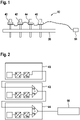
- Fig. 1 shows a schematic view of a first embodiment of an elevator car load measurement system 10 according to the present invention.
- Fig. 2 shows a schematic view of a daisy chain of the force sensors 40, 42, 44, 46.
- the elevator system comprises an elevator car which is held movably by one or more suspension traction means.
- force sensors 40, 42, 44, 46 are installed at the fix point 30 of the suspension traction means of the elevator car 12.
- the force sensor 40, 42, 44, 46 measure the force exerted on the suspension traction means, respectively.
- Fig. 1 four force sensors 40, 42, 44, 46 are installed.
- Each force sensors 40, 42, 44, 46 measure the force exerted on one of the suspension traction means.
- the force sensors 40, 42, 44, 46 are daisy chained, i.e., are connected in series. This means that each force sensor 40, 42, 44, 46 is connected with another force such that all force sensors 40, 42, 44, 46 are connected along a chain.
- the signal of one force sensors 40, 42, 44 is sent to the next force sensor 42, 44, 46 in the daisy chain until the last force sensor 46 in the daisy chain sends the signal to the controller 58.
- the force sensor 40, 42, 44, 46 converts the measured force into a frequency. This conversion can be done in several steps as shown in Fig. 2 . First, the measured force is converted into a voltage (e.g., via a Wheatstone bridge) which is proportional to the measured force. Then, the voltage is converted into a frequency. The wavelength of the frequency generated by the respective force sensor 40, 42, 44, 46 is proportional to the force measured by the respective force sensor 40, 42, 44, 46.
- the frequency signals are rectangular waveform signals, respectively.
- the first force sensor 40 is connected with a second force sensor 42.
- the second force sensor 42 is connected with a third force sensor 44.
- the third force sensor 44 is connected to a fourth force sensor 46.
- the fourth force sensor 46 is connected to a controller 58.
- the first frequency signal 80 with a first frequency is forwarded/sent to the second force sensor 42.
- the second force sensors 42 measures the force exerted on the second force sensor 42.
- the measured force is converted to a second frequency signal 82, wherein the frequency of the second frequency signal 82 is proportional to the measured force.
- the first frequency signal 80 is added to the second frequency signal 82 by the second force sensor 42.
- the addition is carried out as follows: if at least one of the first frequency signal 80 and the second frequency signal 82 has a waveform edge, a waveform edge is generated in the frequency sum signal 84. I.e., if either one of the first frequency signal 80 and the second frequency signal 82 has a waveform edge at a point of time, the frequency sum signal 84 also has waveform edge at that point of time.
- changes (waveform edges) in the square-wave form of the first frequency signal 80 and/or the second frequency signal 82 can be represented by a change of the frequency sum signal 84 (waveform edge).
- the frequencies of the two square-wave form frequency signals are added which is indicated by the "Hz + Hz" in Fig. 2 , i.e., the number of waveform edges in the frequency sum signal 84 per time unit equals the number of waveform edges in the first frequency signal 80 per time unit plus the number of waveform edges in the second frequency signal 82 per time unit.
- the devices denoted with "Hz+Hz" in Fig. 2 can comprise one or several simple logic devices and/or can comprise one or several CPUs and/or ASICs.
- the CPU or ASIC can carry out a complex (logic) function.
- the simple logic device, the CPU and/or ASIC can be adapted such or programmed such that the adding of the frequency signals is carried out as described in the following in connection with Fig. 3 .
- Fig. 3 shows a schematic diagram of the first frequency signal 80, the second frequency signal 82 and the frequency sum signal 84.
- the frequency signals 80, 82, 84 (first frequency signal 80, the second frequency signal 82 and frequency sum signal 84) are drawn shifted along the y-axis in Fig. 3 .
- This shift of the different frequency signals 80, 82, 84 along the y-axis of Fig. 3 is for illustration purposes only, i.e., to show all frequency signals 80, 82, 84 in a single diagram.
- a waveform edge is generated in the frequency sum signal 84.
- a waveform edge is a change of the amplitude from 0 (minimum amplitude) to 1 (maximum amplitude) as well as a change of the amplitude from 1 (maximum amplitude) to 0 (minimum amplitude).
- the first frequency signal 80 has a waveform edge.
- a waveform edge in the frequency sum signal 84 at the point of time t 1 is generated.
- the second frequency signal 82 has a waveform edge.
- a waveform edge in the frequency sum signal 84 at the point of time t 2 is generated.
- the first frequency signal 80 has a waveform edge.
- a waveform edge in the frequency sum signal 84 at point of time t 3 is generated. And so on.
- the frequency sum signal 84 is forwarded/sent from the second force sensor 42 to the third force sensor 44.
- the third force sensors 44 measures the force exerted on the third force sensor 44.
- the measured force is converted to a third frequency signal, wherein the frequency of the third frequency signal is proportional to the measured force.
- the frequency sum signal 84 received from the second force sensor 42 is added to the third frequency signal.
- the addition of the frequency sum signal 84 to the third frequency is done according to the addition of the first frequency signal 80 to the second frequency signal 82. I.e., each time the received frequency sum signal 84 and/or the third frequency signal has a waveform edge, a waveform edge is generated in the frequency sum signal 84 to be outputted by the third force sensor 44. The newly generated frequency sum signal 84 of the third force sensor 44 is sent to the fourth force sensor 46.
- the fourth force sensor 46 measures the force exerted on the fourth force sensor 46.
- the measured force is converted to a fourth frequency signal, wherein the frequency of the fourth frequency signal is proportional to the measured force.
- the frequency sum signal 84 received from the third force sensor 44 is added to the fourth frequency signal. forwarded/sent to the controller 58.
- the addition of the frequency sum signal 84 to the fourth frequency is done according to the addition of the first frequency signal 80 to the second frequency signal 82. I.e., each time the received frequency sum signal 84 and/or the fourth frequency signal has a waveform edge, a waveform edge is generated in the frequency sum signal 84 to be outputted by the fourth force sensor 46.
- the newly generated frequency sum signal 84 of the fourth force sensor 46 is sent to the controller 58.
- more than four (e.g., five, six or more than five) force sensors 40, 42, 44, 46 can be daisy chained this way.
- the last force sensor 46 in the daisy chain can have a CAN interface.
- the frequency sum signal 84 can be sent to the controller 58 and via the CAN interface to other devices.
- the controller 58 can be part of a central control unit of the elevator/elevator system.
- Each force sensor 40, 42, 44, 46 can have a strain gauge.
- Each force sensor 40, 42, 44, 46 of the daisy chain has the same sensitivity, e.g., 1.25 Hz/N. It can have an offset when no force is applied, e.g. 8k Hz for a force of zero Newton.
- the waveform edge is a change from 0 to 1 or from 1 to 0, i.e., a rising or falling edge.
- one of the force sensor 40, 42, 44, 46 If one of the force sensor 40, 42, 44, 46 has a problem/malfunction, it generates a frequency signal with a set error frequency.
- the set error frequency corresponds to a frequency normally not generated, i.e., a frequency which does not correspond to a normally measured force.
- the set error frequency can be a very high frequency or a very low frequency (e.g., 4 kHz or 0 Hz).
- the respective force sensor 40, 42, 44, 46 receives a frequency signal with the set error frequency from the previous force sensor 40, 42, 44, 46 along the daisy chain, the received frequency signal is not added to the frequency signal generated in this force sensor 40, 42, 44, 46, but the force sensor 40, 42, 44, 46 generates a frequency sum signal 84 with the set error frequency. This way, if one force sensor 40, 42, 44, 46 generates a frequency signal with the set error frequency, this signal is forwarded unchanged along the daisy chain and finally received by the controller 58. If the controller 58 receives a signal with the set error frequency, a warning signal is generated and/or the operation of the elevator car 12 is stopped.
- the controller 58 receives a frequency sum signal 84 which contains information from all force sensors 40, 42, 44, 46. I.e., the frequency sum signal 84 comprises all information about the load of the elevator car 12.
- the frequency sum signal 84 is sent from the last force sensor 46 in the daisy chain to the controller 58.
- the controller 58 analyzes the frequency sum signal 84 by determining the number of waveform edges in a set time period (e.g., 1 second). The number of waveform wedges in this set time period is proportional to the sum of the forces measured by the force sensors 40, 42, 44, 46.
- the sensitivity of the force sensors 40, 42, 44, 46, i.e., which frequency corresponds to which measured force is known. Since, the weight of the empty elevator car 12 is known, the load of the elevator car 12 can be determined.
- the forces exerted on the suspension traction means can change over time, but the overall sum remains the same if the load of the elevator car 12 stays the same.
- two frequency signals are received by a pair of force sensors (which generate two frequency signals) and the four frequency signals (two frequency signals from one or two force sensors before in the daisy chain and the two frequency signals of the two force sensors at this point in the chain) are added together in one step.
- All waveform edges in either the received first frequency signal 80 or in the second frequency signal 82 are passed on/transferred to the frequency sum signal 84 which is sent to the next force sensor 42, 44, 46 along the daisy chain or the controller 58 (if the respective force sensor 40, 42, 44, 46 is the last force sensor in the daisy chain).
- the delay time ⁇ t is chosen/set such that the minimal duty cycle of the maximum expected frequency is guaranteed.
- the frequency sum signal 84 which is sent by one force sensor 40, 42, 44 in the daisy chain to the next force sensor 42, 44, 46 can be the so-called first frequency signal 80.
- This so-called first frequency signal 80 is then added to the second frequency signal 82, wherein the so-called second frequency signal 82 is the frequency signal generated in that respective force sensor 40, 42, 44, 46 (based on the measured force).
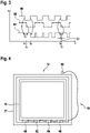
- Fig. 4 shows a schematic view of a second embodiment of an elevator car load measurement system 10 according to the present invention.
- the elevator car 12 comprises a car enclosure module 15 which is disposed within a car traction module 17.
- the car enclosure module 15 is held floatingly within the car traction module 17. This means, that the car enclosure module 15 can move relative to the car traction module 17.
- the car traction module 17 is connected to the suspension traction means.
- the cabin to transport persons and/or goods is located inside the car enclosure module 15.
- the force sensors 40, 42, 44, 46 are disposed between the car enclosure module 15 and the car traction module 17 of the elevator car 12.
- the force sensors 40, 42, 44, 46 are disposed below the car enclosure module 15 along the direction of gravity (the direction of gravity runs in Fig. 4 from top to bottom).
- the force sensors 40, 42, 44, 46 are daisy chained and connected to a controller 58 which is located at the car traction module 17. The controller 58 determines based on the frequency sum signal 84 the load of the elevator car 12.
- the forces measured at the respective force sensors 40, 42, 44, 46 can change over time. E.g., when a person moves from one side of the car enclosure model to the other side. However, the sum of the forces exerted on the force sensors 40, 42, 44, 46 stays the same, as long as the load of the elevator car 12 stays the same.
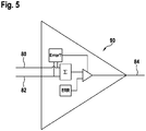
- Fig. 5 shows an error detection mechanism device 90.
- the error detection mechanism device 90 can be part of one or several force sensors 40, 42, 44, 46.
- the summation/outputting of the frequency sum signal of the force sensor 40, 42, 44, 46 can be monitored with the error detection mechanism 90: if the frequency of the first frequency signal 80 (which is received from the previous force sensor 40, 42, 44, 46 in the daisy chain) is out of range, or has a specific error frequency ERR (e.g., 0 Hz for no signal/force sensor 40, 42, 44, 46 broken or 4 kHz for overload of the force sensor 40, 42, 44, 46) then a frequency sum signal 84 with a frequency corresponding to the error frequency ERR is generated and forwarded to the next force sensor 40, 42, 44, 46 in the daisy chain or to the controller 58. If the frequency of the first frequency signal 80 neither is out of range nor has a specific error frequency ERR, the frequency sum signal is generated by adding the first frequency signal 80 to the second frequency signal
Landscapes
- Engineering & Computer Science (AREA)
- Mechanical Engineering (AREA)
- Automation & Control Theory (AREA)
- Physics & Mathematics (AREA)
- General Physics & Mathematics (AREA)
- Computer Networks & Wireless Communication (AREA)
- Maintenance And Inspection Apparatuses For Elevators (AREA)
- Indicating And Signalling Devices For Elevators (AREA)
- Force Measurement Appropriate To Specific Purposes (AREA)
Claims (10)
- Système de mesure de charge de cabine d'ascenseur (10) pour déterminer une charge d'une cabine d'ascenseur (12), le système de mesure de charge de cabine d'ascenseur (10) comprenant :une pluralité d'au moins deux capteurs de force (40, 42, 44, 46) qui sont connectés en guirlande, etun dispositif de commande (58) pour déterminer la charge de la cabine d'ascenseur (12), le système de mesure de charge de cabine d'ascenseur étant caractérisé en ce que chaque capteur de force (40, 42, 44, 46) est adapté pour mesurer une force exercée par la cabine d'ascenseur (12) sur le capteur de force (40, 42, 44, 46) respectif et pour générer un signal de fréquence avec une forme d'onde carrée, le signal de fréquence étant proportionnel à la force mesurée respective,au moins un premier capteur de force (40, 42, 44, 46) de la pluralité de capteurs de force étant adapté de telle sorte qu'un premier signal de fréquence (80) reçu du capteur de force (40, 42, 44, 46) précédent le long de la guirlande est ajouté à un second signal de fréquence (82) généré par le premier capteur de force (40, 42, 44, 46) pour générer etémettre un signal de somme de fréquence (84), le premier signal de fréquence (80) étant ajouté au second signal de fréquence (82) en générant un front de forme d'onde dans le signal de somme de fréquence (84) à un moment donné si le premier signal de fréquence (80) et/ou le second signal de fréquence (82) ont un front de forme d'onde au moment donné respectif ; etau moins un capteur de force (40, 42, 44, 46) de l'au moins un premier capteur de force étant adapté pour transmettre le signal de somme de fréquence (84) au dispositif de commande (58).
- Système de mesure de charge de cabine d'ascenseur (10) selon la revendication 1, dans lequel les capteurs de force (40, 42, 44, 46) sont adaptés de telle sorte que si le premier signal de fréquence (80) et le second signal de fréquence (82) ont un front de forme d'onde au même moment donné qui est un premier moment donné, un front de forme d'onde dans le signal de somme de fréquence (84) est généré au premier moment donné et un front de forme d'onde supplémentaire dans le signal de somme de fréquence (84) est généré à un second moment donné qui se trouve à un temps de retard (δt) après le premier moment donné, en particulier un temps de retard (δt) réglé après le premier moment donné.
- Système de mesure de charge de cabine d'ascenseur (10) selon l'une des revendications précédentes, dans lequel les capteurs de force (40, 42, 44, 46) sont adaptés de telle sorte que, si le capteur de force (40, 42, 44, 46) respectif détecte un dysfonctionnement, le capteur de force (40, 42, 44, 46) respectif génère un second signal de fréquence (82) avec une fréquence d'erreur réglée,
les capteurs de force (40, 42, 44, 46) étant en outre adaptés de telle sorte que, si le premier signal de fréquence (80) a une fréquence qui correspond à la fréquence d'erreur réglée, un signal de somme de fréquence (84) avec la fréquence d'erreur réglée est généré et transmis. - Système de mesure de charge de cabine d'ascenseur (10) selon l'une des revendications précédentes, dans lequel les capteurs de force (40, 42, 44, 46) sont disposés entre un module d'enceinte de cabine (15) et un module de traction de cabine (17) de la cabine d'ascenseur (12), le module d'enceinte de cabine (15) étant maintenu flottant à l'intérieur du module de traction de cabine (17),
les capteurs de force (40, 42, 44, 46) mesurant la force exercée par le module d'enceinte de cabine (15) sur le module de traction de cabine (17), respectivement. - Système de mesure de charge de cabine d'ascenseur (10) selon l'une des revendications 1 à 3, dans lequel les capteurs de force (40, 42, 44, 46) sont disposés à des points fixes (30) de moyens de traction de suspension pour maintenir et déplacer la cabine d'ascenseur (12), les forces mesurées étant des forces exercées par les moyens de traction de suspension sur les capteurs de force (40, 42, 44, 46), respectivement.
- Procédé de détermination d'une charge d'une cabine d'ascenseur (12) par l'intermédiaire d'une pluralité de capteurs de force (40, 42, 44, 46) qui sont connectés en guirlande,
le procédé comprenant les étapes suivantes consistant à :- mesurer les forces exercées par la cabine d'ascenseur (12) sur les capteurs de force (40, 42, 44, 46), respectivement ;- générer des signaux de fréquence avec une forme d'onde carrée, respectivement, le signal de fréquence étant proportionnel à la force mesurée, respectivement ;- recevoir un premier signal de fréquence (80) reçu du capteur de force (40, 42, 44, 46) précédent le long de la guirlande ;- ajouter le premier signal de fréquence (80) à un second signal de fréquence (82) du capteur de force respectif (40, 42, 44, 46) pour générer un signal de somme de fréquence (84) ; le premier signal de fréquence (80) étant ajouté au second signal de fréquence (82) en générant un front de forme d'onde dans le signal de somme de fréquence (84) à un moment donné si le premier signal de fréquence (80) et/ou le second signal de fréquence (82) a un front de forme d'onde au moment donné respectif ;- transmettre le signal de somme de fréquence (84) au capteur de force (42, 44, 46) suivant le long de la guirlande ou à un dispositif de commande (58) ; et- déterminer la charge de la cabine d'ascenseur (12) sur la base du signal de somme de fréquence (84) dans le dispositif de commande (58). - Procédé selon la revendication 6, dans lequel
si le premier signal de fréquence (80) et le second signal de fréquence (82) ont un front de forme d'onde au même moment donné qui est un premier moment donné, un front de forme d'onde dans le signal de somme de fréquence (84) est généré au premier moment donné et un front de forme d'onde supplémentaire dans le signal de somme de fréquence (84) est généré à un second moment donné qui se trouve à un temps de retard (δt) après le premier moment donné, en particulier un temps de retard (δt) réglé après le premier moment donné. - Procédé selon l'une des revendications 6 à 7, dans lequel,
si les capteurs de force (40, 42, 44, 46) respectifs détectent un dysfonctionnement, un second signal de fréquence (82) avec une fréquence d'erreur réglée est généré par le capteur de force (40, 42, 44, 46) respectif, et dans lequel, si le premier signal de fréquence (80) a une fréquence qui correspond à la fréquence d'erreur réglée, un signal de somme de fréquence (84) avec la fréquence d'erreur réglée est généré et transmis. - Procédé selon l'une des revendications 6 à 8, dans lequel
les forces mesurées sont des forces exercées par un module d'enceinte de cabine (15) sur un module de traction de cabine (17) de la cabine d'ascenseur (12), respectivement, le module d'enceinte de cabine (15) étant maintenu flottant à l'intérieur du module de traction de cabine (17). - Procédé selon l'une des revendications 6 à 8, dans lequel
les forces mesurées sont des forces exercées par des moyens de traction de suspension sur les capteurs de force (40, 42, 44, 46) à des points fixes (30) des moyens de traction de suspension, respectivement, les moyens de traction de suspension maintenant et déplaçant la cabine d'ascenseur (12).
Applications Claiming Priority (2)
| Application Number | Priority Date | Filing Date | Title |
|---|---|---|---|
| EP17164301 | 2017-03-31 | ||
| PCT/EP2018/057663 WO2018178023A1 (fr) | 2017-03-31 | 2018-03-26 | Système de mesure de charge de cabine d'ascenseur et procédé de détermination d'une charge d'une cabine d'ascenseur |
Publications (2)
| Publication Number | Publication Date |
|---|---|
| EP3601131A1 EP3601131A1 (fr) | 2020-02-05 |
| EP3601131B1 true EP3601131B1 (fr) | 2022-05-11 |
Family
ID=58464426
Family Applications (1)
| Application Number | Title | Priority Date | Filing Date |
|---|---|---|---|
| EP18712908.5A Active EP3601131B1 (fr) | 2017-03-31 | 2018-03-26 | Système de mesure de charge d'une cabine d'ascenseur et procédé de détermination de charge d'une cabine d'ascenseur |
Country Status (4)
| Country | Link |
|---|---|
| US (1) | US11603285B2 (fr) |
| EP (1) | EP3601131B1 (fr) |
| CN (1) | CN110536853B (fr) |
| WO (1) | WO2018178023A1 (fr) |
Family Cites Families (23)
| Publication number | Priority date | Publication date | Assignee | Title |
|---|---|---|---|---|
| DE3042968A1 (de) * | 1980-11-14 | 1982-07-01 | M.A.N. Maschinenfabrik Augsburg-Nürnberg AG, 8500 Nürnberg | Lastmess- und ausweteeinrichtung fuer aufzugsanlagen |
| IT1190488B (it) * | 1986-02-10 | 1988-02-16 | D M G Spa | Dispositivo elettronico di rilevazione di pesi attraverso sensori applicati sotto il piano d'appaggio dei pesi stessi |
| US4939679A (en) * | 1988-08-09 | 1990-07-03 | Otis Elevator Company | Recalibrating an elevator load measuring system |
| US5004058A (en) * | 1990-03-27 | 1991-04-02 | Cardinal Scale Manufacturing Company | Weigh scale using multiple digital load cells |
| JPH0829894B2 (ja) * | 1990-07-13 | 1996-03-27 | 三菱電機株式会社 | エレベータの秤装置 |
| CN2105677U (zh) * | 1991-08-24 | 1992-05-27 | 福州市电子秤厂 | 轻便式汽车电子衡 |
| US5750945A (en) | 1996-06-03 | 1998-05-12 | Otis Elevator Company | Active elevator hitch |
| JPH10324473A (ja) * | 1997-05-27 | 1998-12-08 | Mitsubishi Denki Bill Techno Service Kk | エレベータにおける異常振動検出装置 |
| US6639156B2 (en) * | 1999-12-30 | 2003-10-28 | Tom J. Luke | Method and device for monitoring inventory |
| RU2271327C2 (ru) * | 2000-05-01 | 2006-03-10 | Инвенцио Аг | Грузоподъемное приспособление для канатных лифтов со встроенным грузоизмерительным устройством |
| US6576849B2 (en) * | 2000-12-01 | 2003-06-10 | Mettler-Toledo, Inc. | Load cell diagnostics and failure prediction weighing apparatus and process |
| WO2002064478A1 (fr) * | 2001-02-09 | 2002-08-22 | Mitsubishi Denki Kabushiki Kaisha | Dispositif de mesure de charge pour ascenseur |
| DE10221628B4 (de) * | 2002-05-15 | 2005-06-23 | Sartorius Ag | Kraftmesssystem mit mehreren Kraftmesszellen und mit einer Schaltung zur Errechnung eines Gesamtsignals |
| JP2005003638A (ja) * | 2003-06-16 | 2005-01-06 | Fujikura Ltd | 障害物検知装置 |
| JP4606236B2 (ja) * | 2005-04-21 | 2011-01-05 | 大和製衡株式会社 | 重量測定方法 |
| BRPI0812423B1 (pt) * | 2007-06-07 | 2019-04-09 | Mettler-Toledo Gmbh | Dispositivo de medição de força múltiplo, e método para monitorar uma condição do dispositivo de medição de força múltiplo. |
| CN201302478Y (zh) * | 2008-11-24 | 2009-09-02 | 李汶波 | 便携式汽车称重仪 |
| CN102042864B (zh) * | 2009-10-23 | 2013-04-03 | 上海裕杰衡器有限公司 | 数字式称重传感器组件及其连接方法 |
| US8304670B2 (en) * | 2010-03-26 | 2012-11-06 | Ut-Battelle, Llc | Portable weighing system with alignment features |
| WO2012031961A1 (fr) * | 2010-09-09 | 2012-03-15 | Inventio Ag | Dispositif de mesure de charge pour une installation d'ascenseur |
| BR112014003862A2 (pt) * | 2011-08-31 | 2017-03-14 | Hirschmann Automation & Control Gmbh | medição de carga no receptor de carga de dispositivos de içamento |
| EP2604563B1 (fr) * | 2011-12-12 | 2015-10-21 | Cedes AG | Dispositif de sécurisation, dispositif d'entraînement et dispositif d'ascenseur |
| CN203889829U (zh) * | 2014-06-05 | 2014-10-22 | 上海托菲机电科技有限公司 | 一种电梯载荷检测的霍尔传感器 |
-
2018
- 2018-03-26 WO PCT/EP2018/057663 patent/WO2018178023A1/fr not_active Ceased
- 2018-03-26 US US16/493,784 patent/US11603285B2/en active Active
- 2018-03-26 CN CN201880023376.0A patent/CN110536853B/zh active Active
- 2018-03-26 EP EP18712908.5A patent/EP3601131B1/fr active Active
Also Published As
| Publication number | Publication date |
|---|---|
| US11603285B2 (en) | 2023-03-14 |
| WO2018178023A1 (fr) | 2018-10-04 |
| CN110536853B (zh) | 2022-04-05 |
| CN110536853A (zh) | 2019-12-03 |
| US20200130989A1 (en) | 2020-04-30 |
| EP3601131A1 (fr) | 2020-02-05 |
Similar Documents
| Publication | Publication Date | Title |
|---|---|---|
| US5233139A (en) | Measurement of traction, operation of brake, friction safety gear, and cable forces of an elevator | |
| US8258415B2 (en) | Method of monitoring the free mobility of a force-measuring device and force-measuring module for applying method | |
| CN101402429B (zh) | 移动物体速度检测装置 | |
| EP3418234B1 (fr) | Ensemble de terminaison d'ascenseur qui fournit une indication de charge de cabine d'ascenseur | |
| EP3708990B1 (fr) | Unité de détection de fibre optique, système de mesure optique, procédé de comptage d'axe, dispositif de comptage d'axe | |
| US20150266701A1 (en) | Load measuring device for an elevator installation | |
| EP3601131B1 (fr) | Système de mesure de charge d'une cabine d'ascenseur et procédé de détermination de charge d'une cabine d'ascenseur | |
| JP2009192347A (ja) | 走行車両の軸重測定装置 | |
| CN109374160A (zh) | 一种用于铁道车辆超偏载检测的钢轨应力传感器 | |
| EP3720743B1 (fr) | Système de détermination d'une vitesse angulaire d'un essieu d'un véhicule ferroviaire et procédé correspondant | |
| NL9100591A (nl) | Drukgevoelige drempel. | |
| EP4286803A2 (fr) | Transducteur intelligent de cellule de charge numerique | |
| CN109186444A (zh) | 一种衡器秤台限位距离的检测装置及检测方法 | |
| KR101725282B1 (ko) | 하중 검출장비를 이용한 교통정보 수집 시스템 | |
| JP2018128289A (ja) | 交通状況監視装置、車両監視システム、交通状況監視方法、および交通状況監視プログラム | |
| CN114235117B (zh) | 车辆轴数确定方法、装置、系统及存储介质 | |
| EP3428101A1 (fr) | Système de surveillance d'ascenseur présente des moyens de traction de suspension et procédé de surveillance de moyens de traction de suspension | |
| CN110455393B (zh) | 一种准确性高的电子皮带秤实时监控方法 | |
| CN207061550U (zh) | 电梯补偿链断链保护装置 | |
| CN107187983A (zh) | 一种电梯补偿链断链保护装置 | |
| JPH0146014B2 (fr) | ||
| EP2569240B1 (fr) | Système de détection de charge dans une cabine d'ascenseur | |
| SU1485029A1 (ru) | Устройство для автоматического измерения массы и длины проката | |
| CN207658882U (zh) | 电梯轿厢受力的实时监测系统及装置 | |
| SU857884A1 (ru) | Способ контрол динамической характеристики первичного преобразовател |
Legal Events
| Date | Code | Title | Description |
|---|---|---|---|
| STAA | Information on the status of an ep patent application or granted ep patent |
Free format text: STATUS: UNKNOWN |
|
| STAA | Information on the status of an ep patent application or granted ep patent |
Free format text: STATUS: THE INTERNATIONAL PUBLICATION HAS BEEN MADE |
|
| PUAI | Public reference made under article 153(3) epc to a published international application that has entered the european phase |
Free format text: ORIGINAL CODE: 0009012 |
|
| STAA | Information on the status of an ep patent application or granted ep patent |
Free format text: STATUS: REQUEST FOR EXAMINATION WAS MADE |
|
| 17P | Request for examination filed |
Effective date: 20190814 |
|
| AK | Designated contracting states |
Kind code of ref document: A1 Designated state(s): AL AT BE BG CH CY CZ DE DK EE ES FI FR GB GR HR HU IE IS IT LI LT LU LV MC MK MT NL NO PL PT RO RS SE SI SK SM TR |
|
| AX | Request for extension of the european patent |
Extension state: BA ME |
|
| DAV | Request for validation of the european patent (deleted) | ||
| DAX | Request for extension of the european patent (deleted) | ||
| STAA | Information on the status of an ep patent application or granted ep patent |
Free format text: STATUS: EXAMINATION IS IN PROGRESS |
|
| 17Q | First examination report despatched |
Effective date: 20210602 |
|
| GRAP | Despatch of communication of intention to grant a patent |
Free format text: ORIGINAL CODE: EPIDOSNIGR1 |
|
| STAA | Information on the status of an ep patent application or granted ep patent |
Free format text: STATUS: GRANT OF PATENT IS INTENDED |
|
| INTG | Intention to grant announced |
Effective date: 20211109 |
|
| GRAS | Grant fee paid |
Free format text: ORIGINAL CODE: EPIDOSNIGR3 |
|
| GRAA | (expected) grant |
Free format text: ORIGINAL CODE: 0009210 |
|
| STAA | Information on the status of an ep patent application or granted ep patent |
Free format text: STATUS: THE PATENT HAS BEEN GRANTED |
|
| AK | Designated contracting states |
Kind code of ref document: B1 Designated state(s): AL AT BE BG CH CY CZ DE DK EE ES FI FR GB GR HR HU IE IS IT LI LT LU LV MC MK MT NL NO PL PT RO RS SE SI SK SM TR |
|
| REG | Reference to a national code |
Ref country code: GB Ref legal event code: FG4D |
|
| REG | Reference to a national code |
Ref country code: CH Ref legal event code: EP |
|
| REG | Reference to a national code |
Ref country code: AT Ref legal event code: REF Ref document number: 1491276 Country of ref document: AT Kind code of ref document: T Effective date: 20220515 |
|
| REG | Reference to a national code |
Ref country code: DE Ref legal event code: R096 Ref document number: 602018035388 Country of ref document: DE |
|
| REG | Reference to a national code |
Ref country code: IE Ref legal event code: FG4D |
|
| REG | Reference to a national code |
Ref country code: LT Ref legal event code: MG9D |
|
| RAP4 | Party data changed (patent owner data changed or rights of a patent transferred) |
Owner name: INVENTIO AG |
|
| REG | Reference to a national code |
Ref country code: NL Ref legal event code: MP Effective date: 20220511 |
|
| REG | Reference to a national code |
Ref country code: AT Ref legal event code: MK05 Ref document number: 1491276 Country of ref document: AT Kind code of ref document: T Effective date: 20220511 |
|
| PG25 | Lapsed in a contracting state [announced via postgrant information from national office to epo] |
Ref country code: SE Free format text: LAPSE BECAUSE OF FAILURE TO SUBMIT A TRANSLATION OF THE DESCRIPTION OR TO PAY THE FEE WITHIN THE PRESCRIBED TIME-LIMIT Effective date: 20220511 Ref country code: PT Free format text: LAPSE BECAUSE OF FAILURE TO SUBMIT A TRANSLATION OF THE DESCRIPTION OR TO PAY THE FEE WITHIN THE PRESCRIBED TIME-LIMIT Effective date: 20220912 Ref country code: NO Free format text: LAPSE BECAUSE OF FAILURE TO SUBMIT A TRANSLATION OF THE DESCRIPTION OR TO PAY THE FEE WITHIN THE PRESCRIBED TIME-LIMIT Effective date: 20220811 Ref country code: NL Free format text: LAPSE BECAUSE OF FAILURE TO SUBMIT A TRANSLATION OF THE DESCRIPTION OR TO PAY THE FEE WITHIN THE PRESCRIBED TIME-LIMIT Effective date: 20220511 Ref country code: LT Free format text: LAPSE BECAUSE OF FAILURE TO SUBMIT A TRANSLATION OF THE DESCRIPTION OR TO PAY THE FEE WITHIN THE PRESCRIBED TIME-LIMIT Effective date: 20220511 Ref country code: HR Free format text: LAPSE BECAUSE OF FAILURE TO SUBMIT A TRANSLATION OF THE DESCRIPTION OR TO PAY THE FEE WITHIN THE PRESCRIBED TIME-LIMIT Effective date: 20220511 Ref country code: GR Free format text: LAPSE BECAUSE OF FAILURE TO SUBMIT A TRANSLATION OF THE DESCRIPTION OR TO PAY THE FEE WITHIN THE PRESCRIBED TIME-LIMIT Effective date: 20220812 Ref country code: FI Free format text: LAPSE BECAUSE OF FAILURE TO SUBMIT A TRANSLATION OF THE DESCRIPTION OR TO PAY THE FEE WITHIN THE PRESCRIBED TIME-LIMIT Effective date: 20220511 Ref country code: ES Free format text: LAPSE BECAUSE OF FAILURE TO SUBMIT A TRANSLATION OF THE DESCRIPTION OR TO PAY THE FEE WITHIN THE PRESCRIBED TIME-LIMIT Effective date: 20220511 Ref country code: BG Free format text: LAPSE BECAUSE OF FAILURE TO SUBMIT A TRANSLATION OF THE DESCRIPTION OR TO PAY THE FEE WITHIN THE PRESCRIBED TIME-LIMIT Effective date: 20220811 Ref country code: AT Free format text: LAPSE BECAUSE OF FAILURE TO SUBMIT A TRANSLATION OF THE DESCRIPTION OR TO PAY THE FEE WITHIN THE PRESCRIBED TIME-LIMIT Effective date: 20220511 |
|
| PG25 | Lapsed in a contracting state [announced via postgrant information from national office to epo] |
Ref country code: RS Free format text: LAPSE BECAUSE OF FAILURE TO SUBMIT A TRANSLATION OF THE DESCRIPTION OR TO PAY THE FEE WITHIN THE PRESCRIBED TIME-LIMIT Effective date: 20220511 Ref country code: PL Free format text: LAPSE BECAUSE OF FAILURE TO SUBMIT A TRANSLATION OF THE DESCRIPTION OR TO PAY THE FEE WITHIN THE PRESCRIBED TIME-LIMIT Effective date: 20220511 Ref country code: LV Free format text: LAPSE BECAUSE OF FAILURE TO SUBMIT A TRANSLATION OF THE DESCRIPTION OR TO PAY THE FEE WITHIN THE PRESCRIBED TIME-LIMIT Effective date: 20220511 Ref country code: IS Free format text: LAPSE BECAUSE OF FAILURE TO SUBMIT A TRANSLATION OF THE DESCRIPTION OR TO PAY THE FEE WITHIN THE PRESCRIBED TIME-LIMIT Effective date: 20220911 |
|
| PG25 | Lapsed in a contracting state [announced via postgrant information from national office to epo] |
Ref country code: SM Free format text: LAPSE BECAUSE OF FAILURE TO SUBMIT A TRANSLATION OF THE DESCRIPTION OR TO PAY THE FEE WITHIN THE PRESCRIBED TIME-LIMIT Effective date: 20220511 Ref country code: SK Free format text: LAPSE BECAUSE OF FAILURE TO SUBMIT A TRANSLATION OF THE DESCRIPTION OR TO PAY THE FEE WITHIN THE PRESCRIBED TIME-LIMIT Effective date: 20220511 Ref country code: RO Free format text: LAPSE BECAUSE OF FAILURE TO SUBMIT A TRANSLATION OF THE DESCRIPTION OR TO PAY THE FEE WITHIN THE PRESCRIBED TIME-LIMIT Effective date: 20220511 Ref country code: EE Free format text: LAPSE BECAUSE OF FAILURE TO SUBMIT A TRANSLATION OF THE DESCRIPTION OR TO PAY THE FEE WITHIN THE PRESCRIBED TIME-LIMIT Effective date: 20220511 Ref country code: DK Free format text: LAPSE BECAUSE OF FAILURE TO SUBMIT A TRANSLATION OF THE DESCRIPTION OR TO PAY THE FEE WITHIN THE PRESCRIBED TIME-LIMIT Effective date: 20220511 Ref country code: CZ Free format text: LAPSE BECAUSE OF FAILURE TO SUBMIT A TRANSLATION OF THE DESCRIPTION OR TO PAY THE FEE WITHIN THE PRESCRIBED TIME-LIMIT Effective date: 20220511 |
|
| REG | Reference to a national code |
Ref country code: DE Ref legal event code: R097 Ref document number: 602018035388 Country of ref document: DE |
|
| PLBE | No opposition filed within time limit |
Free format text: ORIGINAL CODE: 0009261 |
|
| STAA | Information on the status of an ep patent application or granted ep patent |
Free format text: STATUS: NO OPPOSITION FILED WITHIN TIME LIMIT |
|
| PG25 | Lapsed in a contracting state [announced via postgrant information from national office to epo] |
Ref country code: AL Free format text: LAPSE BECAUSE OF FAILURE TO SUBMIT A TRANSLATION OF THE DESCRIPTION OR TO PAY THE FEE WITHIN THE PRESCRIBED TIME-LIMIT Effective date: 20220511 |
|
| 26N | No opposition filed |
Effective date: 20230214 |
|
| PG25 | Lapsed in a contracting state [announced via postgrant information from national office to epo] |
Ref country code: SI Free format text: LAPSE BECAUSE OF FAILURE TO SUBMIT A TRANSLATION OF THE DESCRIPTION OR TO PAY THE FEE WITHIN THE PRESCRIBED TIME-LIMIT Effective date: 20220511 |
|
| PG25 | Lapsed in a contracting state [announced via postgrant information from national office to epo] |
Ref country code: MC Free format text: LAPSE BECAUSE OF FAILURE TO SUBMIT A TRANSLATION OF THE DESCRIPTION OR TO PAY THE FEE WITHIN THE PRESCRIBED TIME-LIMIT Effective date: 20220511 |
|
| REG | Reference to a national code |
Ref country code: CH Ref legal event code: PL |
|
| GBPC | Gb: european patent ceased through non-payment of renewal fee |
Effective date: 20230326 |
|
| REG | Reference to a national code |
Ref country code: BE Ref legal event code: MM Effective date: 20230331 |
|
| PG25 | Lapsed in a contracting state [announced via postgrant information from national office to epo] |
Ref country code: LU Free format text: LAPSE BECAUSE OF NON-PAYMENT OF DUE FEES Effective date: 20230326 |
|
| REG | Reference to a national code |
Ref country code: IE Ref legal event code: MM4A |
|
| PG25 | Lapsed in a contracting state [announced via postgrant information from national office to epo] |
Ref country code: GB Free format text: LAPSE BECAUSE OF NON-PAYMENT OF DUE FEES Effective date: 20230326 |
|
| PG25 | Lapsed in a contracting state [announced via postgrant information from national office to epo] |
Ref country code: LI Free format text: LAPSE BECAUSE OF NON-PAYMENT OF DUE FEES Effective date: 20230331 Ref country code: IT Free format text: LAPSE BECAUSE OF FAILURE TO SUBMIT A TRANSLATION OF THE DESCRIPTION OR TO PAY THE FEE WITHIN THE PRESCRIBED TIME-LIMIT Effective date: 20220511 Ref country code: IE Free format text: LAPSE BECAUSE OF NON-PAYMENT OF DUE FEES Effective date: 20230326 Ref country code: GB Free format text: LAPSE BECAUSE OF NON-PAYMENT OF DUE FEES Effective date: 20230326 Ref country code: FR Free format text: LAPSE BECAUSE OF NON-PAYMENT OF DUE FEES Effective date: 20230331 Ref country code: CH Free format text: LAPSE BECAUSE OF NON-PAYMENT OF DUE FEES Effective date: 20230331 |
|
| PG25 | Lapsed in a contracting state [announced via postgrant information from national office to epo] |
Ref country code: BE Free format text: LAPSE BECAUSE OF NON-PAYMENT OF DUE FEES Effective date: 20230331 |
|
| PG25 | Lapsed in a contracting state [announced via postgrant information from national office to epo] |
Ref country code: BG Free format text: LAPSE BECAUSE OF FAILURE TO SUBMIT A TRANSLATION OF THE DESCRIPTION OR TO PAY THE FEE WITHIN THE PRESCRIBED TIME-LIMIT Effective date: 20220511 |
|
| PG25 | Lapsed in a contracting state [announced via postgrant information from national office to epo] |
Ref country code: BG Free format text: LAPSE BECAUSE OF FAILURE TO SUBMIT A TRANSLATION OF THE DESCRIPTION OR TO PAY THE FEE WITHIN THE PRESCRIBED TIME-LIMIT Effective date: 20220511 |
|
| PGFP | Annual fee paid to national office [announced via postgrant information from national office to epo] |
Ref country code: DE Payment date: 20250327 Year of fee payment: 8 |
|
| PG25 | Lapsed in a contracting state [announced via postgrant information from national office to epo] |
Ref country code: CY Free format text: LAPSE BECAUSE OF FAILURE TO SUBMIT A TRANSLATION OF THE DESCRIPTION OR TO PAY THE FEE WITHIN THE PRESCRIBED TIME-LIMIT; INVALID AB INITIO Effective date: 20180326 |
|
| PG25 | Lapsed in a contracting state [announced via postgrant information from national office to epo] |
Ref country code: HU Free format text: LAPSE BECAUSE OF FAILURE TO SUBMIT A TRANSLATION OF THE DESCRIPTION OR TO PAY THE FEE WITHIN THE PRESCRIBED TIME-LIMIT; INVALID AB INITIO Effective date: 20180326 |
|
| PG25 | Lapsed in a contracting state [announced via postgrant information from national office to epo] |
Ref country code: TR Free format text: LAPSE BECAUSE OF FAILURE TO SUBMIT A TRANSLATION OF THE DESCRIPTION OR TO PAY THE FEE WITHIN THE PRESCRIBED TIME-LIMIT Effective date: 20220511 |