EP3601660B1 - Two-positioning blocking device of a washing drum - Google Patents
Two-positioning blocking device of a washing drum Download PDFInfo
- Publication number
- EP3601660B1 EP3601660B1 EP18739450.7A EP18739450A EP3601660B1 EP 3601660 B1 EP3601660 B1 EP 3601660B1 EP 18739450 A EP18739450 A EP 18739450A EP 3601660 B1 EP3601660 B1 EP 3601660B1
- Authority
- EP
- European Patent Office
- Prior art keywords
- blocking
- positioning
- washing drum
- micro
- spring
- Prior art date
- Legal status (The legal status is an assumption and is not a legal conclusion. Google has not performed a legal analysis and makes no representation as to the accuracy of the status listed.)
- Active
Links
Images

Classifications
-
- D—TEXTILES; PAPER
- D06—TREATMENT OF TEXTILES OR THE LIKE; LAUNDERING; FLEXIBLE MATERIALS NOT OTHERWISE PROVIDED FOR
- D06F—LAUNDERING, DRYING, IRONING, PRESSING OR FOLDING TEXTILE ARTICLES
- D06F37/00—Details specific to washing machines covered by groups D06F21/00 - D06F25/00
- D06F37/30—Driving arrangements
- D06F37/302—Automatic drum positioning
-
- D—TEXTILES; PAPER
- D06—TREATMENT OF TEXTILES OR THE LIKE; LAUNDERING; FLEXIBLE MATERIALS NOT OTHERWISE PROVIDED FOR
- D06F—LAUNDERING, DRYING, IRONING, PRESSING OR FOLDING TEXTILE ARTICLES
- D06F34/00—Details of control systems for washing machines, washer-dryers or laundry dryers
- D06F34/14—Arrangements for detecting or measuring specific parameters
- D06F34/20—Parameters relating to constructional components, e.g. door sensors
-
- D—TEXTILES; PAPER
- D06—TREATMENT OF TEXTILES OR THE LIKE; LAUNDERING; FLEXIBLE MATERIALS NOT OTHERWISE PROVIDED FOR
- D06F—LAUNDERING, DRYING, IRONING, PRESSING OR FOLDING TEXTILE ARTICLES
- D06F2103/00—Parameters monitored or detected for the control of domestic laundry washing machines, washer-dryers or laundry dryers
- D06F2103/24—Spin speed; Drum movements
-
- D—TEXTILES; PAPER
- D06—TREATMENT OF TEXTILES OR THE LIKE; LAUNDERING; FLEXIBLE MATERIALS NOT OTHERWISE PROVIDED FOR
- D06F—LAUNDERING, DRYING, IRONING, PRESSING OR FOLDING TEXTILE ARTICLES
- D06F2105/00—Systems or parameters controlled or affected by the control systems of washing machines, washer-dryers or laundry dryers
- D06F2105/46—Drum speed; Actuation of motors, e.g. starting or interrupting
Definitions
- the invention concerns the automatic positioning device of washing drums, intended to secure blocking of rotation of a washing drum in a starting, predetermined position, where after it is blocked spontaneous rotation of the drum is denied.
- Another group of the blocking systems contains a mechanism, which requires manual impact, in the other words, which are not automatic.
- the systems are operated by a lever arranged in an area of a door of a washing machine. Disadvantage of the solution is, that the washing drum has to be turned to the blocking position manually.
- EP 2 812 476 A1 an automatic device is presented, where two sensors intended for monitoring a position of a washing drum are used, and which comprises a blocking element with cut-out sections.
- the device uses tooth like protrusions with cut-out sections.
- the solution is demanding on a control system, because parallel signals dispatched from the two sensors have to be watched in real time. Furthermore, defining of a superposition of a washing drum is difficult.
- the device is expensive because the sensors are expensive, as well as milling or machining of the blocking mechanism.
- the document doesn't deal with an idea of interconnection of a positioning system with other systems of a washing machine, which is an important aspect for function of the device in view of its correct functionality.
- DE 100 03 474 A1 presents a top-loading washing machine drum locating and stopping procedure and mechanism using locating peg deployed and engaged with notches in drum. Disadvantage of the blocking system is, that a control system has no information, that the washing machine is blocked, and about a position of the blocking element.
- the aim of the present invention is to present a device, which removes above mentioned disadvantages of the state of the art.
- FIG. 1 presents the blocking mechanism of the automatic positioning device according to the invention
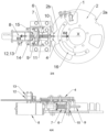
- Fig. 2 presents the automatic positioning device according to the invention without the belt pulley
- Fig. 3 presents the view of a rear side of the blocking mechanism of the automatic positioning device according to the invention
- Fig. 4 presents a detailed cross section of the blocking mechanism according to the Fig. 3 along the axis X, where connection of the blocking element with the scroll bar is depicted.
- the positioning device of a washing drum according to the invention presented in Fig. 1 and 2 , comprises:
- the sensor 1 of a position of a washing drum is arranged in a such place, where it is easy to set its position with regards to the blocking disk 2, in the other words, where ease of maintenance is ensured.
- the blocking element 4 is made of plastic.
- the blocking disk 2 is integrated into a pulley 3 casting.
- the control system of a washing machine evaluates up warding and down warding edges of a digital signal from the sensor 1 of a position of a washing drum by the positioning strip 16 arranged on the blocking disk 2.
- the positioning device uses micro-switches 12, 14 arranged in such place, where they are able to inform the control system by its signal about an actual position of the blocking element 4.
- the positioning device comprises an electromotor 8, which turns a moving screw 9, which moves with a positioning nut 10, which is inserted into a hexagonal opening in the scroll bar 6.
- the hexagonal opening prevents spinning of the positioning nut 10 to ensure only sliding movement of the positioning nut 10 along direction of the axis X of the moving screw 9.
- the positioning nut 10 excites even into an inner opening of a spring 7 to provide a proper position of the spring 7.
- An opposite end of the spring 7 is placed in a resting base 11, to which the spring 7 is resting.
- the electromotor 8 is connected to the driving control unit, which prevents activation of the electromotor 8 as long as rotational speed of a washing drum differs from the predetermined one.
- the scroll bar 6 with the fixed blocking element 4 is controlled by at least one spring 7 and by the positioning nut 10, which is shifting on the moving screw 9 arranged on a shaft of the electromotor 8.
- the positioning strip 16 is arranged on the blocking disk 2 in such way, that it is able to generate an up warding or a down warding edge of the digital signal of the sensor 1 of position of a washing drum.
- control system receives a signal from the sensor 1 of position of a washing drum about the up warding edge, the electromotor 8 is activated and the positioning nut 10 is starting to move in the direction D2.
- the electromotor 8 is activated for a precisely defined period. After that the electromotor 8 is deactivated by the control system of a washing machine.
- the scroll bar 6 is pushed by the spring 7 and moved with the positioning nut 10 towards the blocking disk 2. After that, the blocking element 4 gets contact with the blocking disk 2.
- the mutual touch is achieved in a sufficient distance before the cut-out section arranged in the blocking disk 2a or 2b, to ensure enough time for the positioning nut 10 to get a position, where it can't limit movement of the scroll bar 6 directed towards the termination position, to ensure optimal blocking of the blocking disk 2 by inserting of the blocking element 4 into the cut-out section 2a or 2b. Inserting speed of the blocking element into the cut-out section 2a or 2b depends only on force of the pushing spring, whereas friction resistance is almost negligible.
- the blocking element 4 is in touch with the blocking disk 2 and slides into a position, where it is inserted in the cut-out section 2a or 2b of the blocking disk 2 by impact of force of the spring 7.
- the micro-switches 14 and 15 are switched on during inserting of the blocking element into the cut-out section 2a or 2b.
- the first micro-switch 14 is switched on after minimal insert of the blocking element 4 is performed.
- the first micro-switch 14 is connected directly to the control unit of a driver of a washing drum, which immediately performs interruption of the driver of the washing drum.
- the second micro-switch 15 is switched on after sufficient entry of the blocking element 4 into the cut-out section 2a or 2b is performed.
- the second micro-switch 15 informs the control system of a washing machine about blocking of the washing drum of a washing machine. After that the blocking process is accomplished.
- the positioning nut 10 If the positioning nut 10 is moving in the direction D1 the positioning nut 10 leans on the scroll bar 6, so it is shifted in the direction D1. In the same time the spring 7 is pushed down.
- the movement of the scroll bar 6 is limited by termination barriers and also by third micro-sensor 12, which disconnects source of electronic power from the electromotor 8, when the predetermined position of the scroll bar 6 is reached.
- the third micro-switch 12 is mechanically connected to the fourth micro-switch 13, which when switched signalizes to the control system that the blocking element 4 is positioned in an unlocked position. In this position the blocking disk 2 is able to rotate freely with the shaft and with the washing drum.
- the positioning nut 10 During reversal movement of the positioning nut 10 in the direction D2 the scroll bar 6 is shifted towards the blocking disk 2 by force of the spring 7.
- the positioning nut 10 don't need any stopper in the direction D2.
- the positioning nut 10 is shifted in the direction D2 in a limited time.
- the time limit is constant and adjustable by the control system of the washing machine.
- the positioning nut 10 is shifting in the direction D2 for a predetermined time, so it stops always at the same place.
- the time limit is long enough to accept loss of speed of the positioning nut 10 caused by mechanical friction or delay of response of the driving system.
- the positioning screw 9 is long enough to elongate the time interval of movement of the positioning nut 10.
- the time limit is elongated to ensure shift of the positioning nut 10 in to the right position on the positioning screw 9, where it doesn't prevent moving of the scroll bar 6 to a blocked position in the direction D2.
- Blockage of the blocking disk 2 is a complex process, which uses more systems at one time.
- First of all the control software of a washing machine finds out the actual position of the blocking element 4 by the micro-switch 13 or 15. If all is correctly done the control software sets up a speed of rotation of the washing drum via the actuator drive unit of the washing drum. After that the control unit of a washing machine is waiting for a right moment for activation of the electromotor 8. The right moment is discovered by the sensor 1 of a washing drum.
Landscapes
- Engineering & Computer Science (AREA)
- Textile Engineering (AREA)
- Main Body Construction Of Washing Machines And Laundry Dryers (AREA)
- Control Of Washing Machine And Dryer (AREA)
Priority Applications (1)
| Application Number | Priority Date | Filing Date | Title |
|---|---|---|---|
| SI201831183T SI3601660T1 (sl) | 2017-05-26 | 2018-05-28 | Priprava za blokiranje pralnega bobna v dveh položajih |
Applications Claiming Priority (2)
| Application Number | Priority Date | Filing Date | Title |
|---|---|---|---|
| CZ2017-301A CZ2017301A3 (cs) | 2017-05-26 | 2017-05-26 | Automatické polohovací zařízení pracích bubnů |
| PCT/CZ2018/050025 WO2018215004A1 (en) | 2017-05-26 | 2018-05-28 | Two-positioning blocking device of a washing drums |
Publications (2)
| Publication Number | Publication Date |
|---|---|
| EP3601660A1 EP3601660A1 (en) | 2020-02-05 |
| EP3601660B1 true EP3601660B1 (en) | 2024-10-09 |
Family
ID=62873107
Family Applications (1)
| Application Number | Title | Priority Date | Filing Date |
|---|---|---|---|
| EP18739450.7A Active EP3601660B1 (en) | 2017-05-26 | 2018-05-28 | Two-positioning blocking device of a washing drum |
Country Status (8)
| Country | Link |
|---|---|
| US (1) | US20210123178A1 (cs) |
| EP (1) | EP3601660B1 (cs) |
| CN (1) | CN111032946B (cs) |
| CZ (1) | CZ2017301A3 (cs) |
| DK (1) | DK3601660T3 (cs) |
| ES (1) | ES2994450T3 (cs) |
| SI (1) | SI3601660T1 (cs) |
| WO (1) | WO2018215004A1 (cs) |
Family Cites Families (9)
| Publication number | Priority date | Publication date | Assignee | Title |
|---|---|---|---|---|
| US4763219A (en) * | 1986-11-14 | 1988-08-09 | Tsubakimoto Chain Co. | Overload protection for DC motor-driven linear actuator |
| IT1218255B (it) * | 1988-06-17 | 1990-04-12 | Smeg Spa | Dispositivo di bloccaggio automatico in una posizione prefissata del cestello di lavaggio di macchine lavabiancheria |
| JP2834855B2 (ja) * | 1990-06-26 | 1998-12-14 | 三洋電機株式会社 | ドラム式洗濯機 |
| US5469593A (en) * | 1994-05-02 | 1995-11-28 | Whirlpool Corporation | Basket positioning system for a top loading horizontal axis automatic washer |
| FR2788791B1 (fr) * | 1999-01-27 | 2001-04-13 | Electrolux Syst Blanchisserie | Procede d'indexage en pratique d'un tambour de lave-linge et lave-linge mettant en oeuvre ce procede |
| JP3609789B2 (ja) * | 2002-03-06 | 2005-01-12 | 三洋電機株式会社 | ドラム式洗濯機 |
| ITTO20040691A1 (it) * | 2004-10-08 | 2005-01-08 | Elbi Int Spa | Dispositivo di bloccaggio per un elemento mobile, in particolare per un cestello portabiancheria di una macchina lavatrice a carica dall'alto |
| EP2812476B1 (en) | 2012-02-09 | 2021-05-26 | Electrolux Laundry Systems France SNC | A locking device comprising a moving element, particularly of a washing machine, and associated method |
| CN106480647B (zh) * | 2015-08-31 | 2019-11-12 | 青岛海尔洗衣机有限公司 | 一种内桶的锁止机构及洗衣机 |
-
2017
- 2017-05-26 CZ CZ2017-301A patent/CZ2017301A3/cs unknown
-
2018
- 2018-05-28 EP EP18739450.7A patent/EP3601660B1/en active Active
- 2018-05-28 ES ES18739450T patent/ES2994450T3/es active Active
- 2018-05-28 WO PCT/CZ2018/050025 patent/WO2018215004A1/en not_active Ceased
- 2018-05-28 US US16/617,363 patent/US20210123178A1/en not_active Abandoned
- 2018-05-28 DK DK18739450.7T patent/DK3601660T3/da active
- 2018-05-28 SI SI201831183T patent/SI3601660T1/sl unknown
- 2018-05-28 CN CN201880034660.8A patent/CN111032946B/zh active Active
Also Published As
| Publication number | Publication date |
|---|---|
| WO2018215004A1 (en) | 2018-11-29 |
| CN111032946A (zh) | 2020-04-17 |
| DK3601660T3 (da) | 2025-01-02 |
| CN111032946B (zh) | 2022-08-02 |
| ES2994450T3 (en) | 2025-01-24 |
| US20210123178A1 (en) | 2021-04-29 |
| SI3601660T1 (sl) | 2025-03-31 |
| EP3601660A1 (en) | 2020-02-05 |
| CZ2017301A3 (cs) | 2018-12-05 |
Similar Documents
| Publication | Publication Date | Title |
|---|---|---|
| US8042301B2 (en) | Flap drive | |
| JP5379903B2 (ja) | 可動パーティションを監視する方法及びシステム | |
| KR101728312B1 (ko) | 리드 액추에이터 내 커플링의 작동을 검출하기 위한 방법 및 장치 | |
| CA2464282A1 (en) | Barrier movement operator including timer to close feature | |
| US9341022B2 (en) | Sensing manual drive operation of a movable barrier | |
| US10267078B2 (en) | Vehicular opening/closing body control device | |
| SE461989B (sv) | Laasanordning foer en lucka till en tvaettmaskin, centrifug e d | |
| JP2011094370A (ja) | 挟み込み検出方法、挟み込み検出装置の設定方法、挟み込み検出装置、開閉制御装置 | |
| EP3601660B1 (en) | Two-positioning blocking device of a washing drum | |
| EP1411274A3 (en) | Range switchover apparatus for automatic transmission | |
| US5808250A (en) | Mobile member position detection apparatus | |
| EP0691724B1 (en) | Device for operating a movable part of a motor vehicle | |
| EP2389490B1 (en) | Mechanism for smooth opening and retaining a car door in a desired position | |
| KR100820458B1 (ko) | 전자식 스티어링컬럼록 장치 | |
| EP0992098B1 (en) | Antisqueeze protection | |
| JP7069092B2 (ja) | 係止装置 | |
| KR101739723B1 (ko) | 서랍 자동 개폐장치 | |
| JP3748621B2 (ja) | 硬貨投出装置 | |
| JP2004183409A (ja) | 車両用開閉体の開閉駆動装置 | |
| US20070205760A1 (en) | Device to mechanically secure a magnetic linear position sensor | |
| JP2007224620A (ja) | 回転ドア装置 | |
| KR20070115971A (ko) | 끼임 방지가 감지되는 차량 개방부의 폐쇄 방법 및 장치 | |
| US20030062866A1 (en) | Antisqueeze protection | |
| JP2006002352A (ja) | 自動ドア駆動装置 | |
| NZ710073B2 (en) | Sensing manual drive operation of a movable barrier |
Legal Events
| Date | Code | Title | Description |
|---|---|---|---|
| STAA | Information on the status of an ep patent application or granted ep patent |
Free format text: STATUS: UNKNOWN |
|
| STAA | Information on the status of an ep patent application or granted ep patent |
Free format text: STATUS: THE INTERNATIONAL PUBLICATION HAS BEEN MADE |
|
| PUAI | Public reference made under article 153(3) epc to a published international application that has entered the european phase |
Free format text: ORIGINAL CODE: 0009012 |
|
| STAA | Information on the status of an ep patent application or granted ep patent |
Free format text: STATUS: REQUEST FOR EXAMINATION WAS MADE |
|
| 17P | Request for examination filed |
Effective date: 20191022 |
|
| AK | Designated contracting states |
Kind code of ref document: A1 Designated state(s): AL AT BE BG CH CY CZ DE DK EE ES FI FR GB GR HR HU IE IS IT LI LT LU LV MC MK MT NL NO PL PT RO RS SE SI SK SM TR |
|
| AX | Request for extension of the european patent |
Extension state: BA ME |
|
| DAV | Request for validation of the european patent (deleted) | ||
| DAX | Request for extension of the european patent (deleted) | ||
| STAA | Information on the status of an ep patent application or granted ep patent |
Free format text: STATUS: EXAMINATION IS IN PROGRESS |
|
| 17Q | First examination report despatched |
Effective date: 20220530 |
|
| GRAP | Despatch of communication of intention to grant a patent |
Free format text: ORIGINAL CODE: EPIDOSNIGR1 |
|
| STAA | Information on the status of an ep patent application or granted ep patent |
Free format text: STATUS: GRANT OF PATENT IS INTENDED |
|
| INTG | Intention to grant announced |
Effective date: 20240627 |
|
| GRAS | Grant fee paid |
Free format text: ORIGINAL CODE: EPIDOSNIGR3 |
|
| GRAA | (expected) grant |
Free format text: ORIGINAL CODE: 0009210 |
|
| STAA | Information on the status of an ep patent application or granted ep patent |
Free format text: STATUS: THE PATENT HAS BEEN GRANTED |
|
| AK | Designated contracting states |
Kind code of ref document: B1 Designated state(s): AL AT BE BG CH CY CZ DE DK EE ES FI FR GB GR HR HU IE IS IT LI LT LU LV MC MK MT NL NO PL PT RO RS SE SI SK SM TR |
|
| REG | Reference to a national code |
Ref country code: CH Ref legal event code: EP |
|
| REG | Reference to a national code |
Ref country code: DE Ref legal event code: R096 Ref document number: 602018075193 Country of ref document: DE |
|
| REG | Reference to a national code |
Ref country code: IE Ref legal event code: FG4D |
|
| REG | Reference to a national code |
Ref country code: NL Ref legal event code: FP |
|
| REG | Reference to a national code |
Ref country code: DK Ref legal event code: T3 Effective date: 20241217 Ref country code: SE Ref legal event code: TRGR |
|
| REG | Reference to a national code |
Ref country code: ES Ref legal event code: FG2A Ref document number: 2994450 Country of ref document: ES Kind code of ref document: T3 Effective date: 20250124 |
|
| REG | Reference to a national code |
Ref country code: LT Ref legal event code: MG9D |
|
| PGFP | Annual fee paid to national office [announced via postgrant information from national office to epo] |
Ref country code: SE Payment date: 20250311 Year of fee payment: 8 |
|
| PG25 | Lapsed in a contracting state [announced via postgrant information from national office to epo] |
Ref country code: PT Free format text: LAPSE BECAUSE OF FAILURE TO SUBMIT A TRANSLATION OF THE DESCRIPTION OR TO PAY THE FEE WITHIN THE PRESCRIBED TIME-LIMIT Effective date: 20250210 Ref country code: IS Free format text: LAPSE BECAUSE OF FAILURE TO SUBMIT A TRANSLATION OF THE DESCRIPTION OR TO PAY THE FEE WITHIN THE PRESCRIBED TIME-LIMIT Effective date: 20250209 Ref country code: HR Free format text: LAPSE BECAUSE OF FAILURE TO SUBMIT A TRANSLATION OF THE DESCRIPTION OR TO PAY THE FEE WITHIN THE PRESCRIBED TIME-LIMIT Effective date: 20241009 |
|
| PG25 | Lapsed in a contracting state [announced via postgrant information from national office to epo] |
Ref country code: FI Free format text: LAPSE BECAUSE OF FAILURE TO SUBMIT A TRANSLATION OF THE DESCRIPTION OR TO PAY THE FEE WITHIN THE PRESCRIBED TIME-LIMIT Effective date: 20241009 |
|
| PG25 | Lapsed in a contracting state [announced via postgrant information from national office to epo] |
Ref country code: BG Free format text: LAPSE BECAUSE OF FAILURE TO SUBMIT A TRANSLATION OF THE DESCRIPTION OR TO PAY THE FEE WITHIN THE PRESCRIBED TIME-LIMIT Effective date: 20241009 |
|
| PG25 | Lapsed in a contracting state [announced via postgrant information from national office to epo] |
Ref country code: NO Free format text: LAPSE BECAUSE OF FAILURE TO SUBMIT A TRANSLATION OF THE DESCRIPTION OR TO PAY THE FEE WITHIN THE PRESCRIBED TIME-LIMIT Effective date: 20250109 |
|
| PG25 | Lapsed in a contracting state [announced via postgrant information from national office to epo] |
Ref country code: LV Free format text: LAPSE BECAUSE OF FAILURE TO SUBMIT A TRANSLATION OF THE DESCRIPTION OR TO PAY THE FEE WITHIN THE PRESCRIBED TIME-LIMIT Effective date: 20241009 Ref country code: GR Free format text: LAPSE BECAUSE OF FAILURE TO SUBMIT A TRANSLATION OF THE DESCRIPTION OR TO PAY THE FEE WITHIN THE PRESCRIBED TIME-LIMIT Effective date: 20250110 |
|
| PG25 | Lapsed in a contracting state [announced via postgrant information from national office to epo] |
Ref country code: PL Free format text: LAPSE BECAUSE OF FAILURE TO SUBMIT A TRANSLATION OF THE DESCRIPTION OR TO PAY THE FEE WITHIN THE PRESCRIBED TIME-LIMIT Effective date: 20241009 |
|
| PG25 | Lapsed in a contracting state [announced via postgrant information from national office to epo] |
Ref country code: RS Free format text: LAPSE BECAUSE OF FAILURE TO SUBMIT A TRANSLATION OF THE DESCRIPTION OR TO PAY THE FEE WITHIN THE PRESCRIBED TIME-LIMIT Effective date: 20250109 |
|
| PGFP | Annual fee paid to national office [announced via postgrant information from national office to epo] |
Ref country code: NL Payment date: 20250522 Year of fee payment: 8 |
|
| PG25 | Lapsed in a contracting state [announced via postgrant information from national office to epo] |
Ref country code: SM Free format text: LAPSE BECAUSE OF FAILURE TO SUBMIT A TRANSLATION OF THE DESCRIPTION OR TO PAY THE FEE WITHIN THE PRESCRIBED TIME-LIMIT Effective date: 20241009 |
|
| PGFP | Annual fee paid to national office [announced via postgrant information from national office to epo] |
Ref country code: DE Payment date: 20250519 Year of fee payment: 8 |
|
| PGFP | Annual fee paid to national office [announced via postgrant information from national office to epo] |
Ref country code: ES Payment date: 20250616 Year of fee payment: 8 Ref country code: DK Payment date: 20250521 Year of fee payment: 8 |
|
| REG | Reference to a national code |
Ref country code: DE Ref legal event code: R097 Ref document number: 602018075193 Country of ref document: DE |
|
| PGFP | Annual fee paid to national office [announced via postgrant information from national office to epo] |
Ref country code: BE Payment date: 20250520 Year of fee payment: 8 Ref country code: IT Payment date: 20250530 Year of fee payment: 8 |
|
| PG25 | Lapsed in a contracting state [announced via postgrant information from national office to epo] |
Ref country code: EE Free format text: LAPSE BECAUSE OF FAILURE TO SUBMIT A TRANSLATION OF THE DESCRIPTION OR TO PAY THE FEE WITHIN THE PRESCRIBED TIME-LIMIT Effective date: 20241009 |
|
| PGFP | Annual fee paid to national office [announced via postgrant information from national office to epo] |
Ref country code: FR Payment date: 20250523 Year of fee payment: 8 |
|
| PGFP | Annual fee paid to national office [announced via postgrant information from national office to epo] |
Ref country code: CH Payment date: 20250601 Year of fee payment: 8 |
|
| PG25 | Lapsed in a contracting state [announced via postgrant information from national office to epo] |
Ref country code: RO Free format text: LAPSE BECAUSE OF FAILURE TO SUBMIT A TRANSLATION OF THE DESCRIPTION OR TO PAY THE FEE WITHIN THE PRESCRIBED TIME-LIMIT Effective date: 20241009 |
|
| PGFP | Annual fee paid to national office [announced via postgrant information from national office to epo] |
Ref country code: AT Payment date: 20250519 Year of fee payment: 8 |
|
| PG25 | Lapsed in a contracting state [announced via postgrant information from national office to epo] |
Ref country code: SK Free format text: LAPSE BECAUSE OF FAILURE TO SUBMIT A TRANSLATION OF THE DESCRIPTION OR TO PAY THE FEE WITHIN THE PRESCRIBED TIME-LIMIT Effective date: 20241009 |
|
| PGFP | Annual fee paid to national office [announced via postgrant information from national office to epo] |
Ref country code: TR Payment date: 20250522 Year of fee payment: 8 |
|
| PGFP | Annual fee paid to national office [announced via postgrant information from national office to epo] |
Ref country code: SI Payment date: 20250520 Year of fee payment: 8 |
|
| PLBE | No opposition filed within time limit |
Free format text: ORIGINAL CODE: 0009261 |
|
| STAA | Information on the status of an ep patent application or granted ep patent |
Free format text: STATUS: NO OPPOSITION FILED WITHIN TIME LIMIT |
|
| 26N | No opposition filed |
Effective date: 20250710 |
|
| PG25 | Lapsed in a contracting state [announced via postgrant information from national office to epo] |
Ref country code: LU Free format text: LAPSE BECAUSE OF NON-PAYMENT OF DUE FEES Effective date: 20250528 |
|
| PG25 | Lapsed in a contracting state [announced via postgrant information from national office to epo] |
Ref country code: MC Free format text: LAPSE BECAUSE OF FAILURE TO SUBMIT A TRANSLATION OF THE DESCRIPTION OR TO PAY THE FEE WITHIN THE PRESCRIBED TIME-LIMIT Effective date: 20241009 |
|
| PGFP | Annual fee paid to national office [announced via postgrant information from national office to epo] |
Ref country code: GB Payment date: 20260324 Year of fee payment: 9 |
|
| PG25 | Lapsed in a contracting state [announced via postgrant information from national office to epo] |
Ref country code: IE Free format text: LAPSE BECAUSE OF NON-PAYMENT OF DUE FEES Effective date: 20250528 |
|
| PGFP | Annual fee paid to national office [announced via postgrant information from national office to epo] |
Ref country code: CZ Payment date: 20260317 Year of fee payment: 9 |