EP3601687B1 - Système de stockage d'eau pour zones arides son méthode - Google Patents
Système de stockage d'eau pour zones arides son méthode Download PDFInfo
- Publication number
- EP3601687B1 EP3601687B1 EP18730964.6A EP18730964A EP3601687B1 EP 3601687 B1 EP3601687 B1 EP 3601687B1 EP 18730964 A EP18730964 A EP 18730964A EP 3601687 B1 EP3601687 B1 EP 3601687B1
- Authority
- EP
- European Patent Office
- Prior art keywords
- water
- wall
- storage
- storage system
- devices
- Prior art date
- Legal status (The legal status is an assumption and is not a legal conclusion. Google has not performed a legal analysis and makes no representation as to the accuracy of the status listed.)
- Active
Links
Images


Classifications
-
- E—FIXED CONSTRUCTIONS
- E03—WATER SUPPLY; SEWERAGE
- E03B—INSTALLATIONS OR METHODS FOR OBTAINING, COLLECTING, OR DISTRIBUTING WATER
- E03B3/00—Methods or installations for obtaining or collecting drinking water or tap water
- E03B3/02—Methods or installations for obtaining or collecting drinking water or tap water from rain-water
- E03B3/03—Special vessels for collecting or storing rain-water for use in the household, e.g. water-butts
-
- Y—GENERAL TAGGING OF NEW TECHNOLOGICAL DEVELOPMENTS; GENERAL TAGGING OF CROSS-SECTIONAL TECHNOLOGIES SPANNING OVER SEVERAL SECTIONS OF THE IPC; TECHNICAL SUBJECTS COVERED BY FORMER USPC CROSS-REFERENCE ART COLLECTIONS [XRACs] AND DIGESTS
- Y02—TECHNOLOGIES OR APPLICATIONS FOR MITIGATION OR ADAPTATION AGAINST CLIMATE CHANGE
- Y02A—TECHNOLOGIES FOR ADAPTATION TO CLIMATE CHANGE
- Y02A20/00—Water conservation; Efficient water supply; Efficient water use
-
- Y—GENERAL TAGGING OF NEW TECHNOLOGICAL DEVELOPMENTS; GENERAL TAGGING OF CROSS-SECTIONAL TECHNOLOGIES SPANNING OVER SEVERAL SECTIONS OF THE IPC; TECHNICAL SUBJECTS COVERED BY FORMER USPC CROSS-REFERENCE ART COLLECTIONS [XRACs] AND DIGESTS
- Y02—TECHNOLOGIES OR APPLICATIONS FOR MITIGATION OR ADAPTATION AGAINST CLIMATE CHANGE
- Y02A—TECHNOLOGIES FOR ADAPTATION TO CLIMATE CHANGE
- Y02A20/00—Water conservation; Efficient water supply; Efficient water use
- Y02A20/108—Rainwater harvesting
Definitions
- the present invention relates to a water storage system according to claim 1, preferably for semi-arid regions or for dry regions for receiving and storing water, the water storage system being installed underground and one or more devices for obtaining water from suitable water catchment regions from seasonal precipitation and water from other water resources for storage, has at least one storage space or storage tube for this water, which is connected to one or more devices for receiving water and contains one or more devices for extracting water, which in its system development in functionality and Durability is designed according to cost-effective criteria.
- WO 2006/095384 describes a pipe assembly for a storage tank, comprising a plurality of vertically erected rigid pipes arranged horizontally at a predetermined interval W, and a pipe coupling device for connecting the rigid pipes arranged parallel to each other.
- the tube assembly is covered by a thin plate and forms a storage tank.
- US2014/0346009 discloses a system for collecting rainwater from a house roof or other building, draining it via downspouts and passing it to a filtration system via a collection pipe. From the filter system, the collected rainwater is gravity fed into one or more storage tanks. If required, the rainwater formed can be pumped from the storage tanks to an irrigation system via a distribution system.
- U.S. 1,435,097 describes a cistern having a lower and an upper chamber, a filter separating the two chambers and means for withdrawing liquid from the lower chamber. Furthermore, in the lower chamber near the bottom there is a pipe which extends upwards from the bottom of the lower chamber and is connected to the outside environment and through which water can be taken out. If the water pressure is too low, air can be fed into the lower chamber via another pipe, which increases the water pressure.
- JP H09 221773 discloses an earthquake-proof and watertight boiler, the wall of which consists of a large number of individual blocks, which are each separated from one another by a partition.
- the individual blocks have a space between the inner and outer shell, into which concrete is poured.
- the present invention was therefore based on the object of providing a water storage system which, particularly in semi-arid regions or in dry regions, is able to collect seasonal precipitation, which preferably falls in the form of heavy rain, from suitable water catchment regions (catchment area) to store this water until the next rainy season, if possible while maintaining the water quality, so that during the dry period the population can use it as drinking water and, if necessary, as service water, e.g. B. can be made available for agriculture. Due to this task, another gap in demand can be closed in order to use the water storage system everywhere to store water from other water resources, which does not only refer to semiarid regions.
- the water storage system With the water storage system according to the invention, it is possible to quickly absorb precipitation that falls as heavy rain in semi-arid regions and to forward it to one or more storage rooms and to store the absorbed water over a longer period of time, even at temperatures above 25 C , so that the water stored over a period of several months can gradually be used as drinking water and/or industrial water, e.g. B. can be used for agriculture. It is also possible to compensate for regional and national water deficits by supplying these or other water resources and storing them in the same water storage systems.
- the water storage system according to the invention is designed in such a way that the stored water can be protected from contamination.
- the water storage system according to the invention is preferably used in dry regions or in areas that have suitable water catchment areas (catchment areas).
- This catchment area is characterized by the fact that there are already natural drainage routes for rainwater, which is an advantage in order to absorb this water volume through appropriate hydraulic engineering measures.
- the rainwater is collected via self-cleaning dams and, if necessary, intermediate dams and fed into the system via auxiliary or pipelines using suitable devices that also contribute to reducing bed load.
- the transport systems required for water storage (pumps, etc.), including the pipe system should be dimensioned in such a way that large quantities of water can be taken up and fed into the storage space within a short period of time. With these measures the regional flood risk is reduced at the same time, which reduces damage to infrastructure.
- One object of the present invention is to be able to absorb or store large amounts of water in a short time.
- the corresponding storage spaces should therefore not only have large volumes, but also allow cost optimization in relation to their stability as an underground structure. It has proven to be particularly preferable if the storage space is formed via tunnel tubes, such as are usually built for traffic routes.
- the materials from which tunnel tubes are made have been known for a long time, and it is also known that they have sufficient stability and that the underground construction of tunnel tubes can be controlled technologically.
- the storage space for the water is divided into individual storage units by partitions, which can preferably be connected to one another.
- Each storage unit should be connected to water intake and extraction devices so that each storage unit can be serviced separately and independently of other storage units and, if necessary, serviced or repaired.
- the structure in terms of shape and design of the individual storage units allows the pressure conditions to be balanced, preferably between the individual storage units, so that costs can be saved in the construction of the partition walls of the individual storage units, which can also be referred to as intermediate walls.
- the individual storage units should be able to be connected to one another using suitable devices, for example pipe systems, sliders, valves and/or pumps, so that the storage units can be filled or emptied together through inflow via closable openings in the partition walls or individually via a system control.
- suitable devices for example pipe systems, sliders, valves and/or pumps, so that the storage units can be filled or emptied together through inflow via closable openings in the partition walls or individually via a system control.
- These individual components including possible inlet and outlet lines for the water, are preferably arranged within the recesses of the intermediate walls/partitions and, above all, in a supply tunnel.
- each individual storage unit can also be filled separately with pressure equalization of adjacent storage units.
- the water that is removed for consumption after the storage units have been filled can flow from the higher storage units of the storage space with pressure equalization of adjacent storage units in the direction of the extraction device of lower-lying storage units or be emptied individually with pressure equalization of adjacent storage units.
- individual storage units cannot be used, they can be separated from other storage units.
- the supply tunnel is preferably arranged above the water level of the storage space or the individual storage units.
- the storage space of the present invention does not consist of a cavity more or less square or rectangular in shape and is filled with water from above, but is preferably an elongate cavity, e.g in the form of a tunnel.
- These tunnel tubes have the advantage that the stored water can hardly come into contact with influencing factors that are essentially responsible for external contamination. B. algae growth can be reduced.
- the storage space has such an incline that the pressure on the partition walls of the individual storage units is as low as possible when adjacent storage units are completely filled, but there is an area that is not flooded by the stored water, which can be accessed from the partition wall of a storage unit located above it the underlying storage unit can be used.
- the wall of the storage space or storage units has several tasks. On the one hand, the wall must be stable enough to withstand the external tectonic pressure, on the other hand, it must be ensured that the storage space or the individual storage units can absorb the water pressure and tectonic events. The water should also be able to be stored for a long time and at temperatures above 25 °C. In order to fulfill these tasks, it has proven to be advantageous if the wall consists of an outer wall and an inner wall.
- the outer wall is preferably a concrete wall, which is usually reinforced with construction steel; it can be formed, for example, from tubbings that are customary in tunnel construction.
- the outer wall corresponds to the thickness of such segments.
- the inner wall has a two- or multi-wall or multi-layer structure, a stabilizing inner wall of at least 20 cm thickness, an inner layer applied to it of up to a few cm thickness and, if necessary, one or more inner coatings applied to the inner layer, which can be in the mm range, is preferably made from different special concrete mixtures or mortar mixtures, with corrosion-free reinforcement material being introduced into the stabilizing inner wall and into the inner layer.
- a corrosion-free grid is introduced into the inner layer, which is conductive for electrons and at the same time has high material stability and good properties as a reinforcement material.
- the layer that comes into contact with the stored water usually consists of a mortar suitable for water storage.
- the individual layers of the inner wall of the storage space and the inner wall to the outer wall can be connected to one another via specific connecting elements, preferably via such means or devices that are corrosion-resistant.
- specific connecting elements preferably via such means or devices that are corrosion-resistant.
- the segments are roughened on the concave side after their implementation in order to better connect the stabilizing inner wall with the outer wall.
- the plating or its individual components which can be applied to the corrosion-free and electrically conductive grid using suitable network adhesives, are applied to the stabilizing inner wall with suitable filling and joint materials, i.e. they form the inner layer, which makes inner coatings superfluous.
- the base body of the partition walls which can be up to 2 m thick and possibly more, should usually be made of concrete, but using corrosion-free reinforcement material.
- This base body is anchored to the segments of the outer wall using suitable devices that are introduced into the segments of the outer wall or acted upon by them.
- the stabilizing inner wall applied to the base body of the partition, the inner layer and, if necessary, further inner coatings are preferably approximately identical in construction to those that are applied to the outer wall, the stabilizing inner wall and further layers applied thereto, inner layer and inner coatings, with that Layer structure that is applied to the outer wall, merge into each other.
- the main body of the partition wall should have an inner recess in order to place suction pumps in it, for example, which is essential for their functional activity due to the inner diameter of more than 10 m of the individual storage units.
- suction pumps are used for water extraction or pressure equalization between adjacent storage units, even if the storage units are to be operated separately, and can also be used as circulating pumps for the stored water if no separate pumps are provided for this purpose.
- the cut-out in the dividing wall also saves material on the one hand, and on the other hand it enables the stored water to be controlled directly using the usual manual and technical methods and processes, since there is also direct visual contact through an opening at least 1 m high to the lower-lying storage unit, which has a Device can be closed.
- This opening correlates with the water level, which results from the slope of the storage space and also allows access to the lower storage unit if necessary, as well as manual sampling.
- Access to the cut-out of the partition walls can be achieved via a connecting tunnel to the common supply tunnel above the water level, which also contains the supply and discharge lines for neighboring storage units, i.e. for filling or emptying the storage units.
- This connecting tunnel should be dimensioned in such a way that one can stand upright in it, the exchange of material is possible without hindrance, and inlet and outlet lines and other supply lines can be installed with the ventilation.
- the water storage system according to the invention is to be installed in semi-arid subtropical regions or as a water storage system in arid or tropical regions, the stored water will be exposed to temperatures above 25° C. B. Legionella, is an optimal growth temperature.
- Ion-forming additives and / or substances contain or are exposed to it, which are bactericidal, antiviral and / or fungicidal effective.
- suitable ions are silver and/or copper ions or other substances that can also be present as nanoparticles that have a decontaminating effect.
- self-consumable electrodes in the individual storage chambers, which emit bactericidal, antiviral and/or fungicidal ions, preferably silver or copper electrodes. Water can also be decontaminated by UV radiation, laser treatment and electrotechnical methods and processes.
- the inner layer contains components that are electrically conductive and crosslinked with one another by connecting elements, and are also corrosion-resistant, such as carbon materials. This makes it possible to prevent leakage currents or to derive them via suitable devices via the carbon material, which also applies to overvoltages and, if necessary, serve to protect against lightning.
- the administration and control for receiving and removing the water from the individual storage units and the monitoring of the water storage system as a whole is usually carried out with the help of measuring probes, sensors and technical measures that are connected to corresponding data processing systems and control systems. In this way, the water storage of the entire storage system is automated, the quality assurance of the stored water is ensured and the safety standards for its operation are guaranteed.
- Figures 1 to 4 show a preferred embodiment of the water storage system with a shield diameter of 12 m on a scale, many of which are based on empirical values. Deviating on-site conditions, which are based, for example, on tectonic, geological and static principles, result in different specifications on a case-by-case basis.
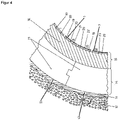
- the radius of the shield diameter is in 4 not to scale, as are the forms of representation given under numbers I-IV for the further layer structure applied to the stabilizing inner wall.
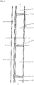
- FIG. 1 shows a side view of the system according to the invention in the longitudinal direction with a storage space 3, which is formed by a tunnel tube in the embodiment shown here and is divided into segments, into storage units 5.
- a storage space 3 which is formed by a tunnel tube in the embodiment shown here and is divided into segments, into storage units 5.
- a supply tunnel 4 from which accesses 8 (see 2 ) into each storage unit 5, namely to the partition walls 6 (see Figs. 2, 3b) of the storage units 5.
- the construction of these tunnel tubes 3 in the subsoil/in the rock can take place using the technologies known in tunnel construction and/or mining.
- the tunnel or the tunnel tube is preferably advanced underground from a suitable starting point, specifically with a length which corresponds to the desired storage volume of the storage space 3 depending on the inner diameter of a storage unit.
- the storage space 3 shown has, starting from the inflow of the water to be stored, an angle of inclination ⁇ which, depending on the specified storage volume, is up to 3500 m 3 per storage unit 5 and its Inner diameter can be about between 1 and 2 degrees of angle according to calculation bases, which can vary up and down depending on the embodiment. Because of the water level, due to the gradient angle ⁇ , there is an area not wetted by water on the dividing wall 6 located above each storage unit 5, which serves as a closable opening 17b for the lower storage unit 5. This proves to be advantageous for operational, service and safety reasons and forms one of the calculation bases for the gradient angle ⁇ of the storage space 3, with this opening 17b being at least 1 m in height.
- the length of the storage space 3 or the storage tube depends on the desired amount of storage depending on the water volume according to the "worst case" per year, taking into account long-term precipitation expectations, if there are no interconnected systems for water supply.
- the entire storage space 3 consists of two storage spaces 3 running as parallel as possible, each of which is assigned a supply tunnel 4, preferably just above the water level of the storage space 3 or the individual storage units 5, in order to simultaneously meet standardized requirements for the operational safety of the storage system as a whole . In this respect, a system development under cost-efficient criteria can be assumed.
- the storage space 3 can be blind tunnels, at the end of which there is only an exit, or can be push-through tunnels, depending on the desired storage volume.
- the location of the penetration for example through a mountain range, must be selected depending on the intended storage volume or the inner diameter of the storage tubes so that this correlates with the gradient angle ⁇ of the storage space 3 . Otherwise, an ascending and, from a calculated section, descending tunneling must be carried out while observing the gradient angle ⁇ . The same can also be done underground if favorable geographic conditions exist.
- the supply pipes 9 should meet the requirements in terms of number and cross-section. Captured water can be completely or partially freed from sediment and/or suspended matter beforehand using suitable hydraulic engineering measures, for example using gabions and/or self-cleaning intermediate dams, as well as using additional pre-filters. The water that has been pre-cleaned in this way is then fed into the water storage system and stored.
- the storage space 3 is divided into individual storage units 5 over the entire length of the storage space, since experience has shown that the water quality can be controlled better with smaller storage volumes.
- the division into storage units 5 is carried out by partitions 6 (see Figure 3b ).
- These partitions 6 consist of a base body 17, which can have different embodiments for static reasons.
- This base body 17 is anchored to the tubbings 15 of the outer wall 14, for which purpose corresponding devices are introduced and/or attached to the tubbings 15 of the outer wall 14 distributed according to calculation bases depending on local conditions (not shown).
- the base bodies 17 of the partition walls 6 preferably contain recesses 17a above their upper half in order to place suction pumps for water extraction, for pressure equalization between adjacent storage units 5 and for circulating the stored water and to install filter systems if necessary.
- the partition walls 6 can contain devices (not shown here) with which water can be transported from one storage unit directly into the next storage chamber, for example via slides, valves or pumps as well as openings or locks for emergency exits in the event of danger (not shown).
- each individual storage unit contains 5 separate devices for receiving water and devices for removing water, so that the Storage units 5 can each be filled or emptied separately from one another, which can be operated separately or simultaneously via IT solutions.
- the connecting tunnel 8 contains, among other things, the supply and discharge lines for the water to neighboring storage units 5.
- the connecting tunnels 8 are designed in such a way that the necessary supply pipes 9 and extraction pipes 10 and other technical equipment can be installed (not shown) and the service personnel can move around freely and the exchange of materials is possible without any problems.
- the storage space 3 or the storage tube is filled via the individual storage units 5 in that the water enters the first lower-lying storage unit via corresponding supply pipes 9 and the water from the first storage unit 5 gradually into the next higher storage unit 5 arrives until the entire storage space 3 is filled.
- the inflow into this storage unit 5 must be stopped and the direct connection to the next higher storage unit 5 must be severed so that the Water pressure 7 on the storage walls is kept as low as possible.
- the water is then fed in via the connecting tunnel 8 via the next higher storage unit 5.
- This filling process can, on the other hand, be carried out via the system control in such a way that each individual storage unit 5 can be filled separately by simultaneously creating a pressure equalization between the individual storage units 5 in order to Partitions 6 burdened by the water pressure as little as possible.
- the water can then in turn be removed via the hydrostatically highest storage unit 5 .
- the remaining water flows according to the slope of the tunnel tube to the tunnel exit from above with pressure equalization between the individual storage units or each storage unit can be emptied individually via the system control, with pressure equalization between the respective storage units.
- the tunnel is driven at an angle of inclination ⁇ of about 1 to 2 degrees upwards or into a mountain massif or underground, depending on the length of a storage unit 5, which consists of the inner diameter of a storage unit 5 and the predetermined volume of a storage unit 5 results.
- the gradient angle ⁇ of the tunnel drive it is therefore advantageous for the gradient angle ⁇ of the tunnel drive to be selected in such a way that the water level of each storage unit 5 when it is full is not higher than the inner or clear diameter of the lower dividing wall 6 and there is open access via an opening of at least 1 m above the partition wall 6 above.
- the same gradient angle ⁇ as in the tunnel drive for the storage rooms 3 must also be maintained in the tunnel drive for the supply tunnel 4, for which tunneling technology can also be used.
- the supply tunnel 4 must be just above the water level of the storage rooms 3 or the individual storage units 5 when they are full (see 1 ). Since the length of the supply tunnel 4 depends on the specified storage space 3 and the inside diameter of a storage unit 5, an economic consideration should be made beforehand between the shield diameter for the storage space 3 and the resulting length of the supply tunnel 4.
- the storage units 5 should not exceed a certain size.
- these volumes are up to a maximum of 3500 m 3 .
- these volumes have an influence on the gradient angle ⁇ of the storage space 3 or on the gradient angle ⁇ of the tunnel drive if free access from the upper partition wall 6 to the storage unit 5 located below is provided.
- the subdivision of the entire storage space 3 into many storage units 5 has the advantage that if repairs should be required on or in a storage unit 5 or similar work, this storage unit 5 can be blocked for water storage, d. H. can be completely emptied without the entire stored or stored water must be completely removed from the storage space 3.
- Another advantage is that if stored water is contaminated in a storage unit 5 and routine methods and procedures fail, only this chamber has to be separated from the entire storage system and not the entire storage system is affected, which usually only affects one of the two storage rooms 3 or storage tubes (see 2 ). As a result, the contaminated storage unit 5 can be made usable again using suitable methods (e.g. shock chlorination). On the other hand, this water can get through decontaminated using separate procedures and used for other purposes after dechlorination.
- suitable methods e.g. shock chlorination
- Appropriate devices are provided for the inflow and removal of the water in the supply tunnel 4, which is above the water level of the storage space 3 or the storage units 5, which are connected via connecting tunnels 8 to each partition wall 6 of the entire storage space 3 in order to separate adjacent storage units 5 to supply.
- such devices are additionally located within the recesses 17a of the partitions 6, which can be accessed via the connecting tunnels 8.
- the water storage system shown consists of two storage spaces (storage tubes) 3, which in the embodiment shown here are designed in the manner of tunnel tubes.
- the water is fed into the storage units 5 of the storage space 3 via the supply pipes 9 arranged in the supply tunnel 4. From the supply pipes 9, the water is conveyed via corresponding further pipes, which branch off from the supply pipes 9 and run into the connecting tunnel 8 in the direction of the partition walls of the storage space 3. fed into the respective storage units 5.
- the water is stored in the entire storage space 3 or in the individual storage units 5 until it is removed.
- the water is extracted from the storage units 5 via corresponding extraction pipes 10, which are also arranged in the connecting tunnels 8, from where the water is diverted into the larger extraction pipes 10 in the supply tunnel 4 and to the control station at the entrance of the storage system (not shown here). to be led.
- the water can be removed via appropriate pumps, with the usual pumps known from hydraulic engineering measures, generally suction pumps, being able to be used.
- the two storage spaces 3 or storage tubes are at such a distance that, in the worst case, experience has shown that it should correspond to twice the shield diameter of the tunnel boring machine (see 2 : affects 2D max), otherwise about half of it.
- the supply tunnel 4 is preferably arranged just above the water level of the storage space 3 of the individual storage units 5 . This prevents water backing up from the storage space 3 or from the storage units 5 from penetrating the supply tunnel 4 unintentionally.
- the supply tunnel is preferably of such a size that it can be entered by people, they can stand up there, if necessary the transport of material and exchange systems with small transport vehicles is possible and sufficient There is space for the technical equipment and necessary installations.
- the supply tunnel 4 which for the sake of simplicity can be created using tunneling technology with tubbing implementation, is therefore not only used to accommodate the supply pipes 9 and extraction pipes 10 of the water and to install the technical and electrical systems, but also to operate and monitor the operation of the system according to the invention system including for maintenance and repair work of the entire storage system.
- the system development is based on standardization according to the criteria of cost efficiency and sustainability.
- the aquifers cut through by the tunnel drive which can carry water permanently or temporarily, can certainly be used for water extraction if impairments to springs in the water catchment area can be ruled out.
- the aquifers cut through the tunnel drive for the storage spaces 3 are less suitable for this purpose than the aquifers cut through the supply tunnel 4.
- Such aquifers may be included in the geological investigations required for tunneling, including Test bores are made along the tunnel route, or are found during tunneling. If such aquifers exist, they are additionally enriched due to hydraulic engineering measures that are necessary to obtain water resources from seasonal precipitation, whereby the water catchment regions in semi-arid regions are usually above 25 km2. Since the water storage system i. i.e. R. positioned in the subsoil of this water catchment region, the aquifers cut through the tunnel drive are also fed via the hydraulic engineering measures.
- tubbings consist of glass fiber material and these segments are designed in such a way that they are suitable for the usual segment implementation within the framework of the tunneling can be used. Since these tubbings are also used for hydraulic engineering methods and processes, they may contain different devices or are incorporated into them for this purpose, which is why such tubbings have different designs depending on the intended use.
- the advantage is that water obtained via aquifers is filtered in a natural way and generally has no contamination, which contributes to cost efficiency.
- the tunnel wall ie the outer wall 14 that extends in the direction of the rock 12
- segments 15 are preferably standard tubbings 15 from the tubbings 15 known in tunneling technology.
- a concrete filling 11 is usually introduced between the rock 12 and the outer wall 14 as part of the tunneling.
- the outer wall 14 of the storage space 3 with the concrete filling 11 primarily serves to intercept the tectonic external pressure 13, to stabilize the segments and to seal the outer wall 14 towards the inside.
- the outer wall 14 or the individual tubbings usually contain suitable reinforcement, which usually consists of mild steel. If there are no frequently changing wet to dry conditions with the external medium, structural steel can be used as reinforcement for the outer wall 14 or for the segments 15.
- the stability of the entire storage space 3 can be increased by adjoining a stabilizing inner wall 18 in the direction of the interior, which preferably intercepts the tensile forces resulting from the water pressure 7 to the outside.
- This stabilizing inner wall 18 should preferably be at least 20 cm with shield diameters of more than 10 m for the tunnel drive, which has a suitable but corrosion-resistant reinforcement.
- the reinforcement of the stabilizing inner wall 18 can, for example, be a glass fiber reinforcement, preferably in the form of rods and/or other bodies made of glass fiber material with a suitable concrete mixture as filling material.
- the concave side of the stabilizing inner wall 18 does not have to have a smooth but a roughened surface.
- the stabilizing inner wall 18 can have devices that ensure a better connection to the inner layer 19 and are preferably linked to the reinforcement of the stabilizing inner wall 18 or are part of this reinforcement.
- the stabilizing inner wall 18 is adjoined by a single-layer or multi-layer structure with further layers 19 or 21, the innermost layer representing the contact layer with the water.
- the inner layer 19 applied to the stabilizing inner wall 18 (see 4 , I), insofar as this does not form the contact layer with the stored water, consists of a special cement mixture that is only a few centimeters thick has good resistance, i.e. it is not only material-resistant against water-chemical influences but is also resistant to mechanical influences.
- the inner layer 19 should preferably also have a decontamination effect if inner coatings 21 are not used.
- the inner layer 19 can be reinforced with a corrosion-free and electrically conductive reinforcement 20, preferably made of textile concrete, including z. B. carbon grids are suitable, which are connected to each other via connecting elements (not shown). It was found that the inner layer 19, reinforced with carbon grids 20, acts like a Faraday cage and shields the storage space like individual storage units or undesired currents, such as e.g. B. leakage currents, via suitable devices (not shown). This also applies to overvoltages that occur (see 4 , I).
- a corrosion-free and electrically conductive reinforcement 20 preferably made of textile concrete, including z. B. carbon grids are suitable, which are connected to each other via connecting elements (not shown). It was found that the inner layer 19, reinforced with carbon grids 20, acts like a Faraday cage and shields the storage space like individual storage units or undesired currents, such as e.g. B. leakage currents, via suitable devices (not shown). This also applies to overvoltages that occur (see 4 , I).
- carbon fibers In order to increase the stability of the inner layer 19 against mechanical and static loads, it can be advantageous to add carbon fibers to the special cement mixture of the inner layer 19 and/or the inner coatings 21, provided these do not form the contact layer with the stored water.
- These carbon fibers increase the mechanical strength of concrete mixes as well as special cement mixes or mortar mixes. Because these carbon fibers are bonded to form components, they are usually soaked in plastic, which also leads to better bonding of the carbon components with concrete mixtures, special cement mixtures or mortar mixtures, and at the same time facilitates the processing of the carbon fibers. With this method, the mechanical strength of the affected layers can be significantly increased.
- the thickness of the carbon fiber composite can be up to 1 mm thick depending on the use, whether it is added to the inner layer 19 or the inner coating(s) 21, and its length can preferably be dimensioned so that it is just below the respective layer thicknesses 19 , 21 lie. It is irrelevant whether the carbon components are added to a concrete mixture, a special cement mixture or a mortar mixture. In exceptional cases, carbon components can also be stabilizing inner wall 18 are added, which results in significantly higher costs than, for example, by using fiberglass components. In order to optimize the mechanical strength, the addition of carbon elements must be determined separately depending on the intended use and layer thickness. Glass fiber components can be used in a similar way, with known materials forming the glass fiber components as connecting material for the individual glass fibers.
- a decontaminating effect which is preferably introduced into the layer that comes into contact with the stored water, can be achieved, for example, by adding suitable ion-forming materials and/or decontaminating substances that can form Cu and Ag ions, for example, with these additives can also be in the form of nanoparticles.
- concentration of these additives in decontaminating materials and/or substances, whether they are used against bacterial, viral or fungal contamination, are based on empirical values, as far as is known.
- This preferably relates to the inner layer 19 or further inner coatings 21 applied thereto, insofar as this represents the contact layer with the stored water.
- the contact layer with the stored water is suitable for interior linings, e.g. the mortar mixtures customary for water reservoirs, which are applied to the inner layer 19 or to one of the inner coatings 21 .
- the z. B. made of ceramic or another type of production (e.g. porcelain stoneware, fired clay).
- a plating 22 to the inner layer 19 instead of the inner coating(s) 21 (see FIG 4 , III), the z. B. made of ceramic or another type of production (e.g. porcelain stoneware, fired clay).
- such components should contain devices on the side facing the inner layer 19 or be designed in shape and size (not shown) in such a way that they make detachment as difficult as possible.
- the surface also have hydrophobic and / or dirt-repellent properties, which z. B. can be achieved via nanotechnologies. If this is not possible, it can prove to be advantageous for the side facing the stored water to be ground smooth and/or polished.
- the inner layer 19 can be advantageous for the inner layer 19 to consist of a plating 22 . Since such building materials, such as tiles, are usually network-bonded to one another for better processing, it is advantageous to use a corrosion-free grid instead of such a carrier network, which has high material stability and good properties as a reinforcement material, and at the same time conducts electrons, for which carbon fibers or a Carbon grid is suitable.
- the individual plates or components that are applied to the corrosion-free and electrically conductive grid using suitable mesh adhesives, i.e. carbon mesh plating 23 (see 4 , IV) are applied to the stabilizing inner wall 18 with suitable filler and joint materials, thus forming the inner layer 19, which makes inner coatings 21 superfluous.
- a decontaminating effect of the filling and/or joint material which is usually a special concrete mixture, has proven to be advantageous for plating 22, including for carbon mesh plating 23, by adding suitable ion-forming materials and/or decontaminating substances, which can also be present as nanoparticles, in the filling and/or joint material.
- This additive or additives can form Cu and Ag ions, for example.
- concentration of these additives in decontaminating materials and/or substances, whether they are used against bacterial, viral or fungal contamination, are based on empirical values, as far as is known, although these additives can have higher concentrations in the case of joint material. If a plating 22 is chosen instead of an inner coating 21, it can prove to be advantageous to reduce the concentration of decontaminating additives in the inner layer 19 or to dispense with them altogether if a carbon mesh plating 23 is involved.
- suitable ion-forming materials for decontamination and/or decontaminating substances as an additive in building materials, preferably in special cement mixtures, in filling and jointing material or in mortar mixtures, can cause problems during processing and also cause higher costs. It therefore proves to be advantageous to bind them to a carrier and/or to introduce and/or attach them to it. If this/these additive(s) is/are incorporated into a carrier, carriers in which these additives can be incorporated are suitable. come for this Materials with a certain microstructure in question, such. B. ceramics, fired clay and / or amorphous materials, which should preferably be present in a round shape up to the mm range, possibly in a nanostructure.
- Carriers that are equipped with decontaminating materials and/or decontaminating substances thus serve as depots, with the advantage that additives to decontaminating materials and/or decontaminating substances that are bound to carriers can be better processed for building materials, or not consume less themselves and thus save costs.
- a known method is, for example, to arrange electrodes in the respective storage chambers 5, which can form Ag ions or Cu ions or other ions with a bactericidal, antiviral and/or fungicidal effect.
- UV irradiation Another well-known method for preventing contamination and for decontamination is UV irradiation.
- UV sources which can vary in energy, are arranged using specific devices, preferably on the respective inner sides of the upper partitions 6 of the individual storage units 5 according to calculation bases, so that an optimum decontamination effect is achieved (not shown).
- the decontaminating effect of positive charges or currents can be used, which can eliminate parasites, bacteria, viruses and fungi.
- electrodes with positive offset voltages, which are pulsed are preferably distributed on the insides of the upper partitions 6 of the storage units 5 according to the calculation bases. They can also be separate devices that are not permanently connected to the partition wall 6 (not shown).
- Laser treatment is considered an effective method to prevent contamination or to decontaminate the stored water.
- suitable laser sources via devices on the insides of the upper and possibly lower partitions 6 of the storage units 5, the energy of which is sufficient or can be varied in such a way that bacteria, viruses, microbes and destroy algae in the water.
- the focal length of the laser points can be changed within the length of a storage unit 5 via devices using lenses in such a way that both the location and size of the laser point can be varied in the entire storage unit 5 as well as that on it related energy (not shown).
Landscapes
- Engineering & Computer Science (AREA)
- Environmental & Geological Engineering (AREA)
- Health & Medical Sciences (AREA)
- Life Sciences & Earth Sciences (AREA)
- Hydrology & Water Resources (AREA)
- Public Health (AREA)
- Water Supply & Treatment (AREA)
- Sewage (AREA)
- Bidet-Like Cleaning Device And Other Flush Toilet Accessories (AREA)
- Preparation Of Clay, And Manufacture Of Mixtures Containing Clay Or Cement (AREA)
- Massaging Devices (AREA)
- Underground Structures, Protecting, Testing And Restoring Foundations (AREA)
Claims (12)
- Système de stockage d'eau pour des régions semi-arides ou des régions arides, y compris pour des régions tropicales et subtropicales, pour la réception et la séquestration d'eau, le système de stockage d'eau étant aménagé sous forme souterraine et comprenant :- un ou plusieurs dispositifs (9) pour la viabilisation et/ou la réception d'eau à partir de précipitations saisonnières ou qui provient d'autres ressources en eau pour le stockage,- au moins un espace de séquestration (3) pour la séquestration d'eau, qui est relié aux un ou plusieurs dispositifs (9) pour la réception d'eau,- un ou plusieurs dispositifs (10) pour le soutirage d'eau,l'espace de séquestration (3) ayant une structure à parois multiples (14, 18, 19, 21, 22, 23), la paroi extérieure (14) ayant une stabilité telle qu'elle résiste à la pression tectonique (13) et la paroi intérieure stabilisatrice (18) amortissant la pression de l'eau (7) et les événements tectoniques, caractérisé en ce que la paroi extérieure (14) est formée par des cuvelages (15), dans lesquels sont introduits ou peuvent être disposés différents dispositifs (9) qui, d'une part, conviennent pour fixer les parois de séparation (6) à la paroi extérieure (14) et, d'autre part, permettent un assemblage de la paroi extérieure (14) avec une paroi intérieure stabilisatrice (18), éventuellement par l'intermédiaire d'éléments de liaison spécifiques.
- Système de stockage d'eau selon la revendication 1, caractérisé en ce que l'espace de séquestration (3) est formé par des tubes à effet tunnel.
- Système de stockage d'eau selon la revendication 1 ou la revendication 2, caractérisé en ce que l'espace de séquestration (3) est divisé en unités de séquestration (5) séparées les unes des autres, qui peuvent être reliées entre elles, chaque unité de séquestration (5) étant pourvue d'un ou plusieurs dispositifs de réception (9) et d'un ou plusieurs dispositifs de soutirage d'eau (10) .
- Système de stockage d'eau selon l'une quelconque des revendications 1 à 3, caractérisé en ce que la paroi intérieure (16) de l'espace de séquestration (3) ou des unités de séquestration (5) présente une structure à deux parois ou plus.
- Système de stockage d'eau selon l'une quelconque des revendications 1 à 4, caractérisé en ce que la paroi intérieure stabilisatrice (18) et la couche intérieure (19) de la paroi intérieure (16) sont constituées d'un matériau en béton muni d'une armature non corrosive.
- Système de stockage d'eau selon la revendication 5, caractérisé en ce que la couche intérieure (19) est un mélange de ciment spécial ou un mélange de mortier et ce mélange est additionné d'additifs de matériaux formant des ions et/ou de substances décontaminantes, qui peuvent également se présenter sous forme de nanoparticules, qui peuvent par exemple former des ions Ag et/ou Cu ou d'autres substances à effet bactéricide, antiviral ou fongicide, ceux-ci étant appliqués sur la couche intérieure (19) sous forme d'un ou de plusieurs revêtements intérieurs correspondants (21).
- Système de stockage d'eau selon la revendication 5, caractérisé en ce qu'une grille stabilisatrice (20) en matériau résistant à la corrosion et conducteur de courant, interconnectée par des éléments de liaison, est introduite dans la couche intérieure (19) en tant que matériau d'armature, qui présente un ou plusieurs dispositifs qui dissipent des courants ou des surtensions.
- Système de stockage d'eau selon l'une quelconque des revendications 5 à 7, caractérisé en ce que des éléments en carbone et/ou des éléments en fibres de verre sont ajoutés à la paroi intérieure stabilisatrice (18) une couche intérieure (19) et ou d'autres revêtements intérieurs (21), à l'exception de la couche de contact venant en contact avec l'eau séquestrée, en une concentration telle que ceux-ci ont des effets positifs optimaux sur la résistance mécanique de leur configuration en fonction de l'épaisseur de couche et de leur configuration.
- Système de stockage d'eau selon l'une quelconque des revendications 5 ou 6, caractérisé en ce qu'au lieu du ou des revêtements intérieurs (21), un placage est appliqué sur la couche intérieure (19), dont les segments individuels sont conçus en termes de forme et de taille et présentent de préférence des dispositifs sur son côté arrière de telle sorte qu'un détachement est rendu difficile, en même temps la surface venant en contact avec l'eau séquestrée présente un degré de dureté élevé, qui, si nécessaire, a des propriétés hydrophobes et/ou antisalissures, sinon est poncée pour être lisse et/ou polie.
- Système de stockage d'eau selon l'une quelconque des revendications 5 à 8, caractérisé en ce que la couche intérieure (19) et les revêtements intérieurs (21) appliqués sur celle-ci sont formés par un placage (22), qui est appliqué sur la paroi intérieure stabilisatrice (18), dont les composants individuels sont fixés sur une grille (20) résistante à la corrosion et conductrice de courant, qui convient bien en tant que matériau d'armature et qui est durable, les grilles étant interconnectées entre elles par des éléments de liaison appropriés, c'est-à-dire constituant un placage en treillis de carbone (23), ces grilles (20) contenant un ou plusieurs dispositifs qui peuvent dissiper des courants et des surtensions.
- Système de stockage d'eau selon les revendications 8 et 9, caractérisé en ce que le matériau de remplissage et de jointoiement pour le placage (22, 23) est un mélange de béton spécial ou des mélanges de béton spécial respectivement différents, les additifs contenant éventuellement des concentrations différentes de matériaux formant des ions et/ou de substances décontaminantes, qui peuvent également se présenter sous la forme de nanoparticules, qui contiennent par exemple des ions Ag et/ou Cu ou d'autres substances qui exercent un effet bactéricide, antiviral ou fongicide.
- Procédé de réception et de séquestration d'eau dans des régions semi-arides ou des régions arides, y compris des régions tropicales et subtropicales, dans lesquelles les précipitations sont généralement saisonnières, procédé dans lequel les précipitations sont recueillies par un système de stockage d'eau aménagé sous forme souterraine, transférées dans un ou plusieurs espaces de séquestration et séquestrées dans ceux-ci, le système de stockage d'eau comprenant :- un ou plusieurs dispositifs det/ou de réception d'eau à partir de précipitations saisonnières ou qui provient d'autres ressources en eau pour le stockage,- au moins un espace de séquestration (3) pour la séquestration d'eau, qui est relié à des dispositifs (9) de réception d'eau,- un ou plusieurs dispositifs (10) de soutirage d'eau, l'espace de séquestration (3) ayant une structure à parois multiples (14, 18, 19, 21, 22, 23), la paroi extérieure (14) ayant une stabilité telle qu'elle résiste à la pression tectonique (13) et la paroi intérieure stabilisatrice (18) amortissant la pression de l'eau (7) et les événements tectoniques, et la paroi extérieure (14) étant formée par des cuvelages (15), dans lesquels sont introduits ou peuvent être disposés différents dispositifs qui, d'une part, conviennent pour fixer les parois de séparation (6) à la paroi extérieure (14) et, d'autre part, permettent un assemblage de la paroi extérieure (14) avec une paroi intérieure stabilisatrice (18), éventuellement par l'intermédiaire d'éléments de liaison spécifiques.
Applications Claiming Priority (3)
| Application Number | Priority Date | Filing Date | Title |
|---|---|---|---|
| DE102017106366 | 2017-03-24 | ||
| DE102017111286 | 2017-05-23 | ||
| PCT/DE2018/100263 WO2018171842A2 (fr) | 2017-03-24 | 2018-03-23 | Système de stockage d'eau pour zones arides |
Publications (3)
| Publication Number | Publication Date |
|---|---|
| EP3601687A2 EP3601687A2 (fr) | 2020-02-05 |
| EP3601687B1 true EP3601687B1 (fr) | 2022-11-09 |
| EP3601687B8 EP3601687B8 (fr) | 2022-12-07 |
Family
ID=62599403
Family Applications (1)
| Application Number | Title | Priority Date | Filing Date |
|---|---|---|---|
| EP18730964.6A Active EP3601687B8 (fr) | 2017-03-24 | 2018-03-23 | Système de stockage d'eau pour zones arides son méthode |
Country Status (3)
| Country | Link |
|---|---|
| EP (1) | EP3601687B8 (fr) |
| ES (1) | ES2938191T3 (fr) |
| WO (1) | WO2018171842A2 (fr) |
Cited By (1)
| Publication number | Priority date | Publication date | Assignee | Title |
|---|---|---|---|---|
| DE102023103410A1 (de) * | 2023-02-13 | 2024-08-14 | Günter Hahn | Pumpspeicherkraftwerk |
Families Citing this family (2)
| Publication number | Priority date | Publication date | Assignee | Title |
|---|---|---|---|---|
| CN113620430B (zh) * | 2021-08-06 | 2022-06-07 | 江苏龙腾工程设计股份有限公司 | 一种智能曝气式浮料模块生物滞留池 |
| DE102022124381A1 (de) * | 2022-09-22 | 2024-03-28 | Reinhold Barth | Verfahren zur Anhebung des Grundwasser-Pegels in vorbestimmten Regionen mithilfe von Meerwasser |
Family Cites Families (4)
| Publication number | Priority date | Publication date | Assignee | Title |
|---|---|---|---|---|
| US1435097A (en) * | 1921-05-10 | 1922-11-07 | George M Anderson | Cistern |
| JP2971800B2 (ja) * | 1996-02-19 | 1999-11-08 | 株式会社大阪造船所 | 耐震性を有する容器 |
| CN101137795A (zh) * | 2005-03-04 | 2008-03-05 | 株式会社托太兹 | 贮留槽用管道集合体 |
| US20140346099A1 (en) * | 2013-03-15 | 2014-11-27 | Leon County, Florida | Methods, Systems, and Apparatus for Rainwater Harvesting and Cistern Storage Integrated with Irrigation |
-
2018
- 2018-03-23 WO PCT/DE2018/100263 patent/WO2018171842A2/fr not_active Ceased
- 2018-03-23 EP EP18730964.6A patent/EP3601687B8/fr active Active
- 2018-03-23 ES ES18730964T patent/ES2938191T3/es active Active
Cited By (1)
| Publication number | Priority date | Publication date | Assignee | Title |
|---|---|---|---|---|
| DE102023103410A1 (de) * | 2023-02-13 | 2024-08-14 | Günter Hahn | Pumpspeicherkraftwerk |
Also Published As
| Publication number | Publication date |
|---|---|
| WO2018171842A3 (fr) | 2018-11-22 |
| WO2018171842A2 (fr) | 2018-09-27 |
| EP3601687B8 (fr) | 2022-12-07 |
| EP3601687A2 (fr) | 2020-02-05 |
| ES2938191T3 (es) | 2023-04-05 |
Similar Documents
| Publication | Publication Date | Title |
|---|---|---|
| EP3345190A1 (fr) | Installation de stockage final de matière radioactive et procédé de fabrication de celle-ci | |
| EP2486988B1 (fr) | Système de traitement de l'eau souterrain pour mines et procédé pour la mise en oeuvre de ce système de traitement d'eau | |
| EP1803851B1 (fr) | Réservoir à eau ou rigole avec système de purification | |
| EP3601687A2 (fr) | Système de stockage d'eau pour zones arides | |
| EP2410095B1 (fr) | Installation de traitement pour eau de pluie | |
| DE102009020202A1 (de) | Kleinkläranlage mit Ringfilter | |
| EP4053348B1 (fr) | Agencement de retenue | |
| DE19756811A1 (de) | Verfahren zur Herstellung eines Behälters und Behältersystem | |
| DE102006039141A1 (de) | Verfahren und Düsen-Saug-Infiltrations-System "Werner Wils" zur Entnahme und/oder Verbringung flüssiger Medien in einem Grundwasserleiter | |
| DE19509467A1 (de) | Anlage und Verfahren zur Entsorgung von Abwasser | |
| DE102021131255A1 (de) | Dezentrale Oberflächenentwässerung mit Druckströmung und direkter Grundwasserauffüllung für urbane Ballungszentren | |
| DE2318102C3 (de) | Brunnen zum Umschichten von Grundwasser aus einem Grundwasserhorizont in einen durch eine undurchlässige Sperrschicht davon getrennten zweiten Grundwasserhorizont | |
| DE102021104931A1 (de) | Wassergebundene Wegedecke | |
| AT503065B1 (de) | Beckenverbund | |
| DE202023106175U1 (de) | Vertikal-Fördereinheit und Fördereinrichtung für Wasser | |
| DE3210659A1 (de) | Verbau, insbesondere fuer schalungen | |
| DE102010030979A1 (de) | Rückhaltevorrichtung für eine Abwasserbehandlungsanordnung, Konstruktionseinheit gebildet aus Rückhaltevorrichtung und Abwasserbehandlungsanordnung | |
| DE69607824T2 (de) | Vorrichtung einer entwässerungsmauer im boden | |
| EP4517012A1 (fr) | Cuve de retenue souterraine et son procédé de fabrication | |
| DE29823806U1 (de) | Versickerungsvorrichtung | |
| DE102023103410A1 (de) | Pumpspeicherkraftwerk | |
| DE9404640U1 (de) | Bauwerk in Fertigbauweise aus Stahlbeton oder einem Ersatzstoff | |
| DE202021002498U1 (de) | Tiefbau Flutwasserauffangsystem | |
| DE102016222017A1 (de) | Endlager für die Lagerung von radioaktivem Material, sowie Verfahren zu seiner Herstellung | |
| EP1144312A2 (fr) | Procede et reacteur pour la decontamination d'eaux souterraines |
Legal Events
| Date | Code | Title | Description |
|---|---|---|---|
| STAA | Information on the status of an ep patent application or granted ep patent |
Free format text: STATUS: UNKNOWN |
|
| STAA | Information on the status of an ep patent application or granted ep patent |
Free format text: STATUS: THE INTERNATIONAL PUBLICATION HAS BEEN MADE |
|
| PUAI | Public reference made under article 153(3) epc to a published international application that has entered the european phase |
Free format text: ORIGINAL CODE: 0009012 |
|
| STAA | Information on the status of an ep patent application or granted ep patent |
Free format text: STATUS: REQUEST FOR EXAMINATION WAS MADE |
|
| 17P | Request for examination filed |
Effective date: 20191022 |
|
| AK | Designated contracting states |
Kind code of ref document: A2 Designated state(s): AL AT BE BG CH CY CZ DE DK EE ES FI FR GB GR HR HU IE IS IT LI LT LU LV MC MK MT NL NO PL PT RO RS SE SI SK SM TR |
|
| AX | Request for extension of the european patent |
Extension state: BA ME |
|
| DAV | Request for validation of the european patent (deleted) | ||
| DAX | Request for extension of the european patent (deleted) | ||
| STAA | Information on the status of an ep patent application or granted ep patent |
Free format text: STATUS: EXAMINATION IS IN PROGRESS |
|
| 17Q | First examination report despatched |
Effective date: 20201020 |
|
| GRAP | Despatch of communication of intention to grant a patent |
Free format text: ORIGINAL CODE: EPIDOSNIGR1 |
|
| STAA | Information on the status of an ep patent application or granted ep patent |
Free format text: STATUS: GRANT OF PATENT IS INTENDED |
|
| INTG | Intention to grant announced |
Effective date: 20220111 |
|
| GRAJ | Information related to disapproval of communication of intention to grant by the applicant or resumption of examination proceedings by the epo deleted |
Free format text: ORIGINAL CODE: EPIDOSDIGR1 |
|
| GRAL | Information related to payment of fee for publishing/printing deleted |
Free format text: ORIGINAL CODE: EPIDOSDIGR3 |
|
| GRAS | Grant fee paid |
Free format text: ORIGINAL CODE: EPIDOSNIGR3 |
|
| STAA | Information on the status of an ep patent application or granted ep patent |
Free format text: STATUS: EXAMINATION IS IN PROGRESS |
|
| GRAP | Despatch of communication of intention to grant a patent |
Free format text: ORIGINAL CODE: EPIDOSNIGR1 |
|
| STAA | Information on the status of an ep patent application or granted ep patent |
Free format text: STATUS: GRANT OF PATENT IS INTENDED |
|
| INTC | Intention to grant announced (deleted) | ||
| INTG | Intention to grant announced |
Effective date: 20220620 |
|
| GRAA | (expected) grant |
Free format text: ORIGINAL CODE: 0009210 |
|
| STAA | Information on the status of an ep patent application or granted ep patent |
Free format text: STATUS: THE PATENT HAS BEEN GRANTED |
|
| AK | Designated contracting states |
Kind code of ref document: B1 Designated state(s): AL AT BE BG CH CY CZ DE DK EE ES FI FR GB GR HR HU IE IS IT LI LT LU LV MC MK MT NL NO PL PT RO RS SE SI SK SM TR |
|
| REG | Reference to a national code |
Ref country code: GB Ref legal event code: FG4D Free format text: NOT ENGLISH |
|
| REG | Reference to a national code |
Ref country code: DE Ref legal event code: R081 Ref document number: 502018011009 Country of ref document: DE Owner name: HAHN, GUENTER, DE Free format text: FORMER OWNER: HAHN, GUENTER, 76534 BADEN-BADEN, DE |
|
| REG | Reference to a national code |
Ref country code: CH Ref legal event code: PK Free format text: BERICHTIGUNG B8 Ref country code: CH Ref legal event code: EP Ref country code: AT Ref legal event code: REF Ref document number: 1530448 Country of ref document: AT Kind code of ref document: T Effective date: 20221115 |
|
| REG | Reference to a national code |
Ref country code: DE Ref legal event code: R096 Ref document number: 502018011009 Country of ref document: DE |
|
| REG | Reference to a national code |
Ref country code: IE Ref legal event code: FG4D Free format text: LANGUAGE OF EP DOCUMENT: GERMAN |
|
| REG | Reference to a national code |
Ref country code: NL Ref legal event code: FP |
|
| REG | Reference to a national code |
Ref country code: LT Ref legal event code: MG9D |
|
| REG | Reference to a national code |
Ref country code: GR Ref legal event code: EP Ref document number: 20230400203 Country of ref document: GR Effective date: 20230307 |
|
| REG | Reference to a national code |
Ref country code: ES Ref legal event code: FG2A Ref document number: 2938191 Country of ref document: ES Kind code of ref document: T3 Effective date: 20230405 |
|
| PG25 | Lapsed in a contracting state [announced via postgrant information from national office to epo] |
Ref country code: SE Free format text: LAPSE BECAUSE OF FAILURE TO SUBMIT A TRANSLATION OF THE DESCRIPTION OR TO PAY THE FEE WITHIN THE PRESCRIBED TIME-LIMIT Effective date: 20221109 Ref country code: PT Free format text: LAPSE BECAUSE OF FAILURE TO SUBMIT A TRANSLATION OF THE DESCRIPTION OR TO PAY THE FEE WITHIN THE PRESCRIBED TIME-LIMIT Effective date: 20230309 Ref country code: NO Free format text: LAPSE BECAUSE OF FAILURE TO SUBMIT A TRANSLATION OF THE DESCRIPTION OR TO PAY THE FEE WITHIN THE PRESCRIBED TIME-LIMIT Effective date: 20230209 Ref country code: LT Free format text: LAPSE BECAUSE OF FAILURE TO SUBMIT A TRANSLATION OF THE DESCRIPTION OR TO PAY THE FEE WITHIN THE PRESCRIBED TIME-LIMIT Effective date: 20221109 Ref country code: FI Free format text: LAPSE BECAUSE OF FAILURE TO SUBMIT A TRANSLATION OF THE DESCRIPTION OR TO PAY THE FEE WITHIN THE PRESCRIBED TIME-LIMIT Effective date: 20221109 |
|
| PG25 | Lapsed in a contracting state [announced via postgrant information from national office to epo] |
Ref country code: RS Free format text: LAPSE BECAUSE OF FAILURE TO SUBMIT A TRANSLATION OF THE DESCRIPTION OR TO PAY THE FEE WITHIN THE PRESCRIBED TIME-LIMIT Effective date: 20221109 Ref country code: PL Free format text: LAPSE BECAUSE OF FAILURE TO SUBMIT A TRANSLATION OF THE DESCRIPTION OR TO PAY THE FEE WITHIN THE PRESCRIBED TIME-LIMIT Effective date: 20221109 Ref country code: LV Free format text: LAPSE BECAUSE OF FAILURE TO SUBMIT A TRANSLATION OF THE DESCRIPTION OR TO PAY THE FEE WITHIN THE PRESCRIBED TIME-LIMIT Effective date: 20221109 Ref country code: IS Free format text: LAPSE BECAUSE OF FAILURE TO SUBMIT A TRANSLATION OF THE DESCRIPTION OR TO PAY THE FEE WITHIN THE PRESCRIBED TIME-LIMIT Effective date: 20230309 Ref country code: HR Free format text: LAPSE BECAUSE OF FAILURE TO SUBMIT A TRANSLATION OF THE DESCRIPTION OR TO PAY THE FEE WITHIN THE PRESCRIBED TIME-LIMIT Effective date: 20221109 |
|
| PG25 | Lapsed in a contracting state [announced via postgrant information from national office to epo] |
Ref country code: SM Free format text: LAPSE BECAUSE OF FAILURE TO SUBMIT A TRANSLATION OF THE DESCRIPTION OR TO PAY THE FEE WITHIN THE PRESCRIBED TIME-LIMIT Effective date: 20221109 Ref country code: RO Free format text: LAPSE BECAUSE OF FAILURE TO SUBMIT A TRANSLATION OF THE DESCRIPTION OR TO PAY THE FEE WITHIN THE PRESCRIBED TIME-LIMIT Effective date: 20221109 Ref country code: EE Free format text: LAPSE BECAUSE OF FAILURE TO SUBMIT A TRANSLATION OF THE DESCRIPTION OR TO PAY THE FEE WITHIN THE PRESCRIBED TIME-LIMIT Effective date: 20221109 Ref country code: DK Free format text: LAPSE BECAUSE OF FAILURE TO SUBMIT A TRANSLATION OF THE DESCRIPTION OR TO PAY THE FEE WITHIN THE PRESCRIBED TIME-LIMIT Effective date: 20221109 Ref country code: CZ Free format text: LAPSE BECAUSE OF FAILURE TO SUBMIT A TRANSLATION OF THE DESCRIPTION OR TO PAY THE FEE WITHIN THE PRESCRIBED TIME-LIMIT Effective date: 20221109 |
|
| REG | Reference to a national code |
Ref country code: DE Ref legal event code: R097 Ref document number: 502018011009 Country of ref document: DE |
|
| PG25 | Lapsed in a contracting state [announced via postgrant information from national office to epo] |
Ref country code: SK Free format text: LAPSE BECAUSE OF FAILURE TO SUBMIT A TRANSLATION OF THE DESCRIPTION OR TO PAY THE FEE WITHIN THE PRESCRIBED TIME-LIMIT Effective date: 20221109 Ref country code: AL Free format text: LAPSE BECAUSE OF FAILURE TO SUBMIT A TRANSLATION OF THE DESCRIPTION OR TO PAY THE FEE WITHIN THE PRESCRIBED TIME-LIMIT Effective date: 20221109 |
|
| PLBE | No opposition filed within time limit |
Free format text: ORIGINAL CODE: 0009261 |
|
| STAA | Information on the status of an ep patent application or granted ep patent |
Free format text: STATUS: NO OPPOSITION FILED WITHIN TIME LIMIT |
|
| 26N | No opposition filed |
Effective date: 20230810 |
|
| PG25 | Lapsed in a contracting state [announced via postgrant information from national office to epo] |
Ref country code: MC Free format text: LAPSE BECAUSE OF FAILURE TO SUBMIT A TRANSLATION OF THE DESCRIPTION OR TO PAY THE FEE WITHIN THE PRESCRIBED TIME-LIMIT Effective date: 20221109 |
|
| PG25 | Lapsed in a contracting state [announced via postgrant information from national office to epo] |
Ref country code: SI Free format text: LAPSE BECAUSE OF FAILURE TO SUBMIT A TRANSLATION OF THE DESCRIPTION OR TO PAY THE FEE WITHIN THE PRESCRIBED TIME-LIMIT Effective date: 20221109 |
|
| REG | Reference to a national code |
Ref country code: BE Ref legal event code: MM Effective date: 20230331 |
|
| PG25 | Lapsed in a contracting state [announced via postgrant information from national office to epo] |
Ref country code: LU Free format text: LAPSE BECAUSE OF NON-PAYMENT OF DUE FEES Effective date: 20230323 |
|
| REG | Reference to a national code |
Ref country code: IE Ref legal event code: MM4A |
|
| PG25 | Lapsed in a contracting state [announced via postgrant information from national office to epo] |
Ref country code: IE Free format text: LAPSE BECAUSE OF NON-PAYMENT OF DUE FEES Effective date: 20230323 |
|
| PG25 | Lapsed in a contracting state [announced via postgrant information from national office to epo] |
Ref country code: BE Free format text: LAPSE BECAUSE OF NON-PAYMENT OF DUE FEES Effective date: 20230331 |
|
| PG25 | Lapsed in a contracting state [announced via postgrant information from national office to epo] |
Ref country code: BG Free format text: LAPSE BECAUSE OF FAILURE TO SUBMIT A TRANSLATION OF THE DESCRIPTION OR TO PAY THE FEE WITHIN THE PRESCRIBED TIME-LIMIT Effective date: 20221109 |
|
| PG25 | Lapsed in a contracting state [announced via postgrant information from national office to epo] |
Ref country code: BG Free format text: LAPSE BECAUSE OF FAILURE TO SUBMIT A TRANSLATION OF THE DESCRIPTION OR TO PAY THE FEE WITHIN THE PRESCRIBED TIME-LIMIT Effective date: 20221109 |
|
| PGFP | Annual fee paid to national office [announced via postgrant information from national office to epo] |
Ref country code: DE Payment date: 20250331 Year of fee payment: 8 |
|
| PGFP | Annual fee paid to national office [announced via postgrant information from national office to epo] |
Ref country code: NL Payment date: 20250327 Year of fee payment: 8 |
|
| PGFP | Annual fee paid to national office [announced via postgrant information from national office to epo] |
Ref country code: ES Payment date: 20250416 Year of fee payment: 8 |
|
| PGFP | Annual fee paid to national office [announced via postgrant information from national office to epo] |
Ref country code: IT Payment date: 20250327 Year of fee payment: 8 |
|
| PGFP | Annual fee paid to national office [announced via postgrant information from national office to epo] |
Ref country code: CH Payment date: 20250401 Year of fee payment: 8 |
|
| PG25 | Lapsed in a contracting state [announced via postgrant information from national office to epo] |
Ref country code: CY Free format text: LAPSE BECAUSE OF FAILURE TO SUBMIT A TRANSLATION OF THE DESCRIPTION OR TO PAY THE FEE WITHIN THE PRESCRIBED TIME-LIMIT; INVALID AB INITIO Effective date: 20180323 |
|
| PG25 | Lapsed in a contracting state [announced via postgrant information from national office to epo] |
Ref country code: HU Free format text: LAPSE BECAUSE OF FAILURE TO SUBMIT A TRANSLATION OF THE DESCRIPTION OR TO PAY THE FEE WITHIN THE PRESCRIBED TIME-LIMIT; INVALID AB INITIO Effective date: 20180323 |
|
| PGFP | Annual fee paid to national office [announced via postgrant information from national office to epo] |
Ref country code: GB Payment date: 20260327 Year of fee payment: 9 |
|
| PGFP | Annual fee paid to national office [announced via postgrant information from national office to epo] |
Ref country code: AT Payment date: 20260325 Year of fee payment: 9 |
|
| PGFP | Annual fee paid to national office [announced via postgrant information from national office to epo] |
Ref country code: FR Payment date: 20260326 Year of fee payment: 9 |
|
| PGFP | Annual fee paid to national office [announced via postgrant information from national office to epo] |
Ref country code: TR Payment date: 20260313 Year of fee payment: 9 |
|
| REG | Reference to a national code |
Ref country code: CH Ref legal event code: U11 Free format text: ST27 STATUS EVENT CODE: U-0-0-U10-U11 (AS PROVIDED BY THE NATIONAL OFFICE) Effective date: 20260423 |
|
| PGFP | Annual fee paid to national office [announced via postgrant information from national office to epo] |
Ref country code: GR Payment date: 20260326 Year of fee payment: 9 |