EP3601759B1 - Verfahren und system zur steuerung mindestens einer dosiervorrichtung und/oder eines motors - Google Patents
Verfahren und system zur steuerung mindestens einer dosiervorrichtung und/oder eines motors Download PDFInfo
- Publication number
- EP3601759B1 EP3601759B1 EP18777216.5A EP18777216A EP3601759B1 EP 3601759 B1 EP3601759 B1 EP 3601759B1 EP 18777216 A EP18777216 A EP 18777216A EP 3601759 B1 EP3601759 B1 EP 3601759B1
- Authority
- EP
- European Patent Office
- Prior art keywords
- exhaust
- temperature
- additive
- evaporation chamber
- exh
- Prior art date
- Legal status (The legal status is an assumption and is not a legal conclusion. Google has not performed a legal analysis and makes no representation as to the accuracy of the status listed.)
- Active
Links
Images


Classifications
-
- F—MECHANICAL ENGINEERING; LIGHTING; HEATING; WEAPONS; BLASTING
- F01—MACHINES OR ENGINES IN GENERAL; ENGINE PLANTS IN GENERAL; STEAM ENGINES
- F01N—GAS-FLOW SILENCERS OR EXHAUST APPARATUS FOR MACHINES OR ENGINES IN GENERAL; GAS-FLOW SILENCERS OR EXHAUST APPARATUS FOR INTERNAL-COMBUSTION ENGINES
- F01N9/00—Electrical control of exhaust gas treating apparatus
-
- F—MECHANICAL ENGINEERING; LIGHTING; HEATING; WEAPONS; BLASTING
- F01—MACHINES OR ENGINES IN GENERAL; ENGINE PLANTS IN GENERAL; STEAM ENGINES
- F01N—GAS-FLOW SILENCERS OR EXHAUST APPARATUS FOR MACHINES OR ENGINES IN GENERAL; GAS-FLOW SILENCERS OR EXHAUST APPARATUS FOR INTERNAL-COMBUSTION ENGINES
- F01N3/00—Exhaust or silencing apparatus having means for purifying, rendering innocuous, or otherwise treating exhaust
- F01N3/08—Exhaust or silencing apparatus having means for purifying, rendering innocuous, or otherwise treating exhaust for rendering innocuous
- F01N3/10—Exhaust or silencing apparatus having means for purifying, rendering innocuous, or otherwise treating exhaust for rendering innocuous by thermal or catalytic conversion of noxious components of exhaust
- F01N3/18—Exhaust or silencing apparatus having means for purifying, rendering innocuous, or otherwise treating exhaust for rendering innocuous by thermal or catalytic conversion of noxious components of exhaust characterised by methods of operation; Control
- F01N3/20—Exhaust or silencing apparatus having means for purifying, rendering innocuous, or otherwise treating exhaust for rendering innocuous by thermal or catalytic conversion of noxious components of exhaust characterised by methods of operation; Control specially adapted for catalytic conversion
- F01N3/206—Adding periodically or continuously substances to exhaust gases for promoting purification, e.g. catalytic material in liquid form, NOx reducing agents
- F01N3/208—Control of selective catalytic reduction [SCR], e.g. by adjusting the dosing of reducing agent
-
- B—PERFORMING OPERATIONS; TRANSPORTING
- B01—PHYSICAL OR CHEMICAL PROCESSES OR APPARATUS IN GENERAL
- B01D—SEPARATION
- B01D53/00—Separation of gases or vapours; Recovering vapours of volatile solvents from gases; Chemical or biological purification of waste gases, e.g. engine exhaust gases, smoke, fumes, flue gases, aerosols
- B01D53/34—Chemical or biological purification of waste gases
- B01D53/92—Chemical or biological purification of waste gases of engine exhaust gases
- B01D53/94—Chemical or biological purification of waste gases of engine exhaust gases by catalytic processes
- B01D53/9404—Removing only nitrogen compounds
- B01D53/9409—Nitrogen oxides
- B01D53/9413—Processes characterised by a specific catalyst
- B01D53/9418—Processes characterised by a specific catalyst for removing nitrogen oxides by selective catalytic reduction [SCR] using a reducing agent in a lean exhaust gas
-
- F—MECHANICAL ENGINEERING; LIGHTING; HEATING; WEAPONS; BLASTING
- F01—MACHINES OR ENGINES IN GENERAL; ENGINE PLANTS IN GENERAL; STEAM ENGINES
- F01N—GAS-FLOW SILENCERS OR EXHAUST APPARATUS FOR MACHINES OR ENGINES IN GENERAL; GAS-FLOW SILENCERS OR EXHAUST APPARATUS FOR INTERNAL-COMBUSTION ENGINES
- F01N3/00—Exhaust or silencing apparatus having means for purifying, rendering innocuous, or otherwise treating exhaust
- F01N3/08—Exhaust or silencing apparatus having means for purifying, rendering innocuous, or otherwise treating exhaust for rendering innocuous
- F01N3/10—Exhaust or silencing apparatus having means for purifying, rendering innocuous, or otherwise treating exhaust for rendering innocuous by thermal or catalytic conversion of noxious components of exhaust
- F01N3/18—Exhaust or silencing apparatus having means for purifying, rendering innocuous, or otherwise treating exhaust for rendering innocuous by thermal or catalytic conversion of noxious components of exhaust characterised by methods of operation; Control
- F01N3/20—Exhaust or silencing apparatus having means for purifying, rendering innocuous, or otherwise treating exhaust for rendering innocuous by thermal or catalytic conversion of noxious components of exhaust characterised by methods of operation; Control specially adapted for catalytic conversion
- F01N3/206—Adding periodically or continuously substances to exhaust gases for promoting purification, e.g. catalytic material in liquid form, NOx reducing agents
-
- F—MECHANICAL ENGINEERING; LIGHTING; HEATING; WEAPONS; BLASTING
- F01—MACHINES OR ENGINES IN GENERAL; ENGINE PLANTS IN GENERAL; STEAM ENGINES
- F01N—GAS-FLOW SILENCERS OR EXHAUST APPARATUS FOR MACHINES OR ENGINES IN GENERAL; GAS-FLOW SILENCERS OR EXHAUST APPARATUS FOR INTERNAL-COMBUSTION ENGINES
- F01N3/00—Exhaust or silencing apparatus having means for purifying, rendering innocuous, or otherwise treating exhaust
- F01N3/08—Exhaust or silencing apparatus having means for purifying, rendering innocuous, or otherwise treating exhaust for rendering innocuous
- F01N3/10—Exhaust or silencing apparatus having means for purifying, rendering innocuous, or otherwise treating exhaust for rendering innocuous by thermal or catalytic conversion of noxious components of exhaust
- F01N3/24—Exhaust or silencing apparatus having means for purifying, rendering innocuous, or otherwise treating exhaust for rendering innocuous by thermal or catalytic conversion of noxious components of exhaust characterised by constructional aspects of converting apparatus
- F01N3/28—Construction of catalytic reactors
- F01N3/2892—Exhaust flow directors or the like, e.g. upstream of catalytic device
-
- F—MECHANICAL ENGINEERING; LIGHTING; HEATING; WEAPONS; BLASTING
- F01—MACHINES OR ENGINES IN GENERAL; ENGINE PLANTS IN GENERAL; STEAM ENGINES
- F01N—GAS-FLOW SILENCERS OR EXHAUST APPARATUS FOR MACHINES OR ENGINES IN GENERAL; GAS-FLOW SILENCERS OR EXHAUST APPARATUS FOR INTERNAL-COMBUSTION ENGINES
- F01N9/00—Electrical control of exhaust gas treating apparatus
- F01N9/005—Electrical control of exhaust gas treating apparatus using models instead of sensors to determine operating characteristics of exhaust systems, e.g. calculating catalyst temperature instead of measuring it directly
-
- F—MECHANICAL ENGINEERING; LIGHTING; HEATING; WEAPONS; BLASTING
- F02—COMBUSTION ENGINES; HOT-GAS OR COMBUSTION-PRODUCT ENGINE PLANTS
- F02D—CONTROLLING COMBUSTION ENGINES
- F02D41/00—Electrical control of supply of combustible mixture or its constituents
- F02D41/0025—Controlling engines characterised by use of non-liquid fuels, pluralities of fuels, or non-fuel substances added to the combustible mixtures
- F02D41/0047—Controlling exhaust gas recirculation [EGR]
-
- F—MECHANICAL ENGINEERING; LIGHTING; HEATING; WEAPONS; BLASTING
- F02—COMBUSTION ENGINES; HOT-GAS OR COMBUSTION-PRODUCT ENGINE PLANTS
- F02D—CONTROLLING COMBUSTION ENGINES
- F02D41/00—Electrical control of supply of combustible mixture or its constituents
- F02D41/30—Controlling fuel injection
- F02D41/38—Controlling fuel injection of the high pressure type
- F02D41/3809—Common rail control systems
- F02D41/3836—Controlling the fuel pressure
-
- F—MECHANICAL ENGINEERING; LIGHTING; HEATING; WEAPONS; BLASTING
- F02—COMBUSTION ENGINES; HOT-GAS OR COMBUSTION-PRODUCT ENGINE PLANTS
- F02D—CONTROLLING COMBUSTION ENGINES
- F02D41/00—Electrical control of supply of combustible mixture or its constituents
- F02D41/30—Controlling fuel injection
- F02D41/38—Controlling fuel injection of the high pressure type
- F02D41/40—Controlling fuel injection of the high pressure type with means for controlling injection timing or duration
- F02D41/401—Controlling injection timing
-
- F—MECHANICAL ENGINEERING; LIGHTING; HEATING; WEAPONS; BLASTING
- F01—MACHINES OR ENGINES IN GENERAL; ENGINE PLANTS IN GENERAL; STEAM ENGINES
- F01N—GAS-FLOW SILENCERS OR EXHAUST APPARATUS FOR MACHINES OR ENGINES IN GENERAL; GAS-FLOW SILENCERS OR EXHAUST APPARATUS FOR INTERNAL-COMBUSTION ENGINES
- F01N2560/00—Exhaust systems with means for detecting or measuring exhaust gas components or characteristics
- F01N2560/06—Exhaust systems with means for detecting or measuring exhaust gas components or characteristics the means being a temperature sensor
-
- F—MECHANICAL ENGINEERING; LIGHTING; HEATING; WEAPONS; BLASTING
- F01—MACHINES OR ENGINES IN GENERAL; ENGINE PLANTS IN GENERAL; STEAM ENGINES
- F01N—GAS-FLOW SILENCERS OR EXHAUST APPARATUS FOR MACHINES OR ENGINES IN GENERAL; GAS-FLOW SILENCERS OR EXHAUST APPARATUS FOR INTERNAL-COMBUSTION ENGINES
- F01N2560/00—Exhaust systems with means for detecting or measuring exhaust gas components or characteristics
- F01N2560/07—Exhaust systems with means for detecting or measuring exhaust gas components or characteristics the means being an exhaust gas flow rate or velocity meter or sensor, intake flow meters only when exclusively used to determine exhaust gas parameters
-
- F—MECHANICAL ENGINEERING; LIGHTING; HEATING; WEAPONS; BLASTING
- F01—MACHINES OR ENGINES IN GENERAL; ENGINE PLANTS IN GENERAL; STEAM ENGINES
- F01N—GAS-FLOW SILENCERS OR EXHAUST APPARATUS FOR MACHINES OR ENGINES IN GENERAL; GAS-FLOW SILENCERS OR EXHAUST APPARATUS FOR INTERNAL-COMBUSTION ENGINES
- F01N2610/00—Adding substances to exhaust gases
- F01N2610/02—Adding substances to exhaust gases the substance being ammonia or urea
-
- F—MECHANICAL ENGINEERING; LIGHTING; HEATING; WEAPONS; BLASTING
- F01—MACHINES OR ENGINES IN GENERAL; ENGINE PLANTS IN GENERAL; STEAM ENGINES
- F01N—GAS-FLOW SILENCERS OR EXHAUST APPARATUS FOR MACHINES OR ENGINES IN GENERAL; GAS-FLOW SILENCERS OR EXHAUST APPARATUS FOR INTERNAL-COMBUSTION ENGINES
- F01N2900/00—Details of electrical control or of the monitoring of the exhaust gas treating apparatus
- F01N2900/04—Methods of control or diagnosing
- F01N2900/0412—Methods of control or diagnosing using pre-calibrated maps, tables or charts
-
- F—MECHANICAL ENGINEERING; LIGHTING; HEATING; WEAPONS; BLASTING
- F01—MACHINES OR ENGINES IN GENERAL; ENGINE PLANTS IN GENERAL; STEAM ENGINES
- F01N—GAS-FLOW SILENCERS OR EXHAUST APPARATUS FOR MACHINES OR ENGINES IN GENERAL; GAS-FLOW SILENCERS OR EXHAUST APPARATUS FOR INTERNAL-COMBUSTION ENGINES
- F01N2900/00—Details of electrical control or of the monitoring of the exhaust gas treating apparatus
- F01N2900/04—Methods of control or diagnosing
- F01N2900/0422—Methods of control or diagnosing measuring the elapsed time
-
- F—MECHANICAL ENGINEERING; LIGHTING; HEATING; WEAPONS; BLASTING
- F01—MACHINES OR ENGINES IN GENERAL; ENGINE PLANTS IN GENERAL; STEAM ENGINES
- F01N—GAS-FLOW SILENCERS OR EXHAUST APPARATUS FOR MACHINES OR ENGINES IN GENERAL; GAS-FLOW SILENCERS OR EXHAUST APPARATUS FOR INTERNAL-COMBUSTION ENGINES
- F01N2900/00—Details of electrical control or of the monitoring of the exhaust gas treating apparatus
- F01N2900/06—Parameters used for exhaust control or diagnosing
- F01N2900/08—Parameters used for exhaust control or diagnosing said parameters being related to the engine
-
- F—MECHANICAL ENGINEERING; LIGHTING; HEATING; WEAPONS; BLASTING
- F01—MACHINES OR ENGINES IN GENERAL; ENGINE PLANTS IN GENERAL; STEAM ENGINES
- F01N—GAS-FLOW SILENCERS OR EXHAUST APPARATUS FOR MACHINES OR ENGINES IN GENERAL; GAS-FLOW SILENCERS OR EXHAUST APPARATUS FOR INTERNAL-COMBUSTION ENGINES
- F01N2900/00—Details of electrical control or of the monitoring of the exhaust gas treating apparatus
- F01N2900/06—Parameters used for exhaust control or diagnosing
- F01N2900/14—Parameters used for exhaust control or diagnosing said parameters being related to the exhaust gas
- F01N2900/1404—Exhaust gas temperature
-
- F—MECHANICAL ENGINEERING; LIGHTING; HEATING; WEAPONS; BLASTING
- F01—MACHINES OR ENGINES IN GENERAL; ENGINE PLANTS IN GENERAL; STEAM ENGINES
- F01N—GAS-FLOW SILENCERS OR EXHAUST APPARATUS FOR MACHINES OR ENGINES IN GENERAL; GAS-FLOW SILENCERS OR EXHAUST APPARATUS FOR INTERNAL-COMBUSTION ENGINES
- F01N2900/00—Details of electrical control or of the monitoring of the exhaust gas treating apparatus
- F01N2900/06—Parameters used for exhaust control or diagnosing
- F01N2900/14—Parameters used for exhaust control or diagnosing said parameters being related to the exhaust gas
- F01N2900/1411—Exhaust gas flow rate, e.g. mass flow rate or volumetric flow rate
-
- F—MECHANICAL ENGINEERING; LIGHTING; HEATING; WEAPONS; BLASTING
- F01—MACHINES OR ENGINES IN GENERAL; ENGINE PLANTS IN GENERAL; STEAM ENGINES
- F01N—GAS-FLOW SILENCERS OR EXHAUST APPARATUS FOR MACHINES OR ENGINES IN GENERAL; GAS-FLOW SILENCERS OR EXHAUST APPARATUS FOR INTERNAL-COMBUSTION ENGINES
- F01N2900/00—Details of electrical control or of the monitoring of the exhaust gas treating apparatus
- F01N2900/06—Parameters used for exhaust control or diagnosing
- F01N2900/16—Parameters used for exhaust control or diagnosing said parameters being related to the exhaust apparatus, e.g. particulate filter or catalyst
- F01N2900/1602—Temperature of exhaust gas apparatus
-
- F—MECHANICAL ENGINEERING; LIGHTING; HEATING; WEAPONS; BLASTING
- F01—MACHINES OR ENGINES IN GENERAL; ENGINE PLANTS IN GENERAL; STEAM ENGINES
- F01N—GAS-FLOW SILENCERS OR EXHAUST APPARATUS FOR MACHINES OR ENGINES IN GENERAL; GAS-FLOW SILENCERS OR EXHAUST APPARATUS FOR INTERNAL-COMBUSTION ENGINES
- F01N2900/00—Details of electrical control or of the monitoring of the exhaust gas treating apparatus
- F01N2900/06—Parameters used for exhaust control or diagnosing
- F01N2900/18—Parameters used for exhaust control or diagnosing said parameters being related to the system for adding a substance into the exhaust
- F01N2900/1806—Properties of reducing agent or dosing system
- F01N2900/1811—Temperature
-
- F—MECHANICAL ENGINEERING; LIGHTING; HEATING; WEAPONS; BLASTING
- F01—MACHINES OR ENGINES IN GENERAL; ENGINE PLANTS IN GENERAL; STEAM ENGINES
- F01N—GAS-FLOW SILENCERS OR EXHAUST APPARATUS FOR MACHINES OR ENGINES IN GENERAL; GAS-FLOW SILENCERS OR EXHAUST APPARATUS FOR INTERNAL-COMBUSTION ENGINES
- F01N2900/00—Details of electrical control or of the monitoring of the exhaust gas treating apparatus
- F01N2900/06—Parameters used for exhaust control or diagnosing
- F01N2900/18—Parameters used for exhaust control or diagnosing said parameters being related to the system for adding a substance into the exhaust
- F01N2900/1806—Properties of reducing agent or dosing system
- F01N2900/1812—Flow rate
-
- F—MECHANICAL ENGINEERING; LIGHTING; HEATING; WEAPONS; BLASTING
- F01—MACHINES OR ENGINES IN GENERAL; ENGINE PLANTS IN GENERAL; STEAM ENGINES
- F01N—GAS-FLOW SILENCERS OR EXHAUST APPARATUS FOR MACHINES OR ENGINES IN GENERAL; GAS-FLOW SILENCERS OR EXHAUST APPARATUS FOR INTERNAL-COMBUSTION ENGINES
- F01N2900/00—Details of electrical control or of the monitoring of the exhaust gas treating apparatus
- F01N2900/06—Parameters used for exhaust control or diagnosing
- F01N2900/18—Parameters used for exhaust control or diagnosing said parameters being related to the system for adding a substance into the exhaust
- F01N2900/1806—Properties of reducing agent or dosing system
- F01N2900/1821—Injector parameters
-
- F—MECHANICAL ENGINEERING; LIGHTING; HEATING; WEAPONS; BLASTING
- F02—COMBUSTION ENGINES; HOT-GAS OR COMBUSTION-PRODUCT ENGINE PLANTS
- F02D—CONTROLLING COMBUSTION ENGINES
- F02D41/00—Electrical control of supply of combustible mixture or its constituents
- F02D41/30—Controlling fuel injection
- F02D41/38—Controlling fuel injection of the high pressure type
- F02D2041/389—Controlling fuel injection of the high pressure type for injecting directly into the cylinder
-
- F—MECHANICAL ENGINEERING; LIGHTING; HEATING; WEAPONS; BLASTING
- F02—COMBUSTION ENGINES; HOT-GAS OR COMBUSTION-PRODUCT ENGINE PLANTS
- F02D—CONTROLLING COMBUSTION ENGINES
- F02D2200/00—Input parameters for engine control
- F02D2200/02—Input parameters for engine control the parameters being related to the engine
- F02D2200/04—Engine intake system parameters
-
- F—MECHANICAL ENGINEERING; LIGHTING; HEATING; WEAPONS; BLASTING
- F02—COMBUSTION ENGINES; HOT-GAS OR COMBUSTION-PRODUCT ENGINE PLANTS
- F02D—CONTROLLING COMBUSTION ENGINES
- F02D2200/00—Input parameters for engine control
- F02D2200/02—Input parameters for engine control the parameters being related to the engine
- F02D2200/06—Fuel or fuel supply system parameters
- F02D2200/0614—Actual fuel mass or fuel injection amount
-
- Y—GENERAL TAGGING OF NEW TECHNOLOGICAL DEVELOPMENTS; GENERAL TAGGING OF CROSS-SECTIONAL TECHNOLOGIES SPANNING OVER SEVERAL SECTIONS OF THE IPC; TECHNICAL SUBJECTS COVERED BY FORMER USPC CROSS-REFERENCE ART COLLECTIONS [XRACs] AND DIGESTS
- Y02—TECHNOLOGIES OR APPLICATIONS FOR MITIGATION OR ADAPTATION AGAINST CLIMATE CHANGE
- Y02T—CLIMATE CHANGE MITIGATION TECHNOLOGIES RELATED TO TRANSPORTATION
- Y02T10/00—Road transport of goods or passengers
- Y02T10/10—Internal combustion engine [ICE] based vehicles
- Y02T10/12—Improving ICE efficiencies
-
- Y—GENERAL TAGGING OF NEW TECHNOLOGICAL DEVELOPMENTS; GENERAL TAGGING OF CROSS-SECTIONAL TECHNOLOGIES SPANNING OVER SEVERAL SECTIONS OF THE IPC; TECHNICAL SUBJECTS COVERED BY FORMER USPC CROSS-REFERENCE ART COLLECTIONS [XRACs] AND DIGESTS
- Y02—TECHNOLOGIES OR APPLICATIONS FOR MITIGATION OR ADAPTATION AGAINST CLIMATE CHANGE
- Y02T—CLIMATE CHANGE MITIGATION TECHNOLOGIES RELATED TO TRANSPORTATION
- Y02T10/00—Road transport of goods or passengers
- Y02T10/10—Internal combustion engine [ICE] based vehicles
- Y02T10/40—Engine management systems
Definitions
- the present invention relates to a method for controlling at least one of a dosage device and an engine, according to the preamble of claim 1.
- the present invention also relates to a system arranged for controlling at least one of a dosage device and an engine, according to the preamble of claim 14.
- the invention also relates to a computer program and a computer-readable medium, which implement the method according to the invention.
- Such emission standards often comprise requirements defining acceptable limits of exhaust emissions from combustion engines in for example vehicles. For example, emission levels of nitrogen oxides NO x , hydrocarbons C x H y , carbon monoxide CO and particles PM are often regulated by such standards for most types of vehicles. Vehicles equipped with combustion engines typically give rise to such emissions in varying degrees. In this document, the invention will be described mainly for its application in vehicles. However, the invention may be used in substantially all applications where combustion engines are used, for example in vessels such as ships or aeroplanes/helicopters, wherein regulations and standards for such applications limit emissions from the combustion engines.
- a common way of treating exhausts from a combustion engine includes a so-called catalytic purification process, which is why vehicles equipped with a combustion engine usually comprise at least one catalyst.
- catalysts There are different types of catalysts, where the different respective types may be suitable depending on for example the combustion concept, combustion strategies and/or fuel types which are used in the vehicles, and/or the types of compounds in the exhaust stream to be purified.
- nitrogen oxides NO x In relation to at least nitrous gases (nitrogen monoxide, nitrogen dioxide), referred to below as nitrogen oxides NO x , vehicles often comprise a catalyst, wherein an additive is supplied to the exhaust stream resulting from the combustion in the combustion engine, in order to reduce nitrogen oxides NO x , primarily to nitrogen gas and aqueous vapour.
- SCR catalysts are for example a commonly used type of catalyst for this type of reduction, primarily for heavy goods vehicles.
- SCR catalysts usually use ammonia NH 3 , or a composition from which ammonia may be generated/formed, such as e.g. AdBlue, as an additive to reduce the amount of nitrogen oxides NO x in the exhausts.
- the additive is injected into the exhaust stream resulting from the combustion engine upstream of the catalyst.
- the additive added to the catalyst is adsorbed (stored) in the catalyst, in the form of ammonia NH 3 , so that a redox-reaction may occur between nitrogen oxides NO x in the exhausts and ammonia NH 3 available via the additive.
- JP 2013122218 A1 An example of a method of detecting deposits of urea in an exhaust passage is shown in JP 2013122218 A1 .
- the additive being injected into the exhaust stream is thus very important for the reduction of the nitrogen oxides NO x in the exhausts.
- the control of the amount to be injected is not very exact/reliable, which may be problematic.
- residues/precipitates/crystallisations of additive are formed downstream of the dosage device injecting the additive into the exhaust stream e.g. in an evaporation chamber.
- Such additive residues/precipitates/crystallisations (hereafter commonly denoted residues) of additive being formed in the exhaust treatment system potentially increase the back pressure in the exhaust treatment system, and therefore potentially also increase the fuel consumption for the engine.
- additive residues in the exhaust treatment system may have a negative effect on the general purification performance of the exhaust treatment system, since the additive residues in the evaporation chamber reduces the evaporation efficiency, which may result in that too little evaporated additive reaches the SCR catalyst.
- the increased back pressure and/or the less efficient exhaust purification of the exhaust treatment system may also result in a number of control system related problems.
- the one or more control systems arranged for controlling the exhaust treatment system may be unaware of these problems, and may thus keep on controlling the system based on the assumption that the back pressure is not increased and/or that an efficient reduction of nitrogen oxides NO x is effected by the system.
- the reduction of the nitrogen oxides NO x in the exhausts may become deficient/unacceptable, and may result in that requirements in emission standards are not fulfilled.
- An object of the present invention is at least partly solve at least some of the above mentioned problems/disadvantages.
- the at least one time dependent condition C i is determined based also on one or more of an exhaust mass flow M exh ⁇ of the exhaust stream, and an additive mass flow M add ⁇ being injected by the dosage device into the exhaust stream.
- the at least one interpretation of the internal temperature T i is determined based on one or more in the group of:
- the at least one interpretation of the internal temperature T i is determined based also on at least one measurement of the internal temperature T i performed by at least one internal temperature sensor arranged at the at least one position P i at the internal wall of the evaporation chamber.
- the temperature model utilizes the exhaust temperature T exh for the exhaust stream, the exhaust mass flow M exh ⁇ , and the additive mass flow M add ⁇ being injected into the exhaust stream as input parameters.
- the exhaust mass flow M exh ⁇ is determined based on at least one in the group of:
- the at least one time dependent condition C i is related to a mass M add _ wall of the additive being present at the at least one position P i at the internal wall of the evaporation chamber.
- the mass M add _ wall of the additive is determined based at least on one or more of the at least one interpretation of the internal temperature T i , the additive mass flow M add ⁇ being injected into the exhaust stream, the exhaust mass flow M exh ⁇ for the exhaust stream, and a time period t add during which the additive is injected into the exhaust stream.
- control of the dosage device includes control of one or more in the group of:
- control of the engine includes control of one or more in the group of:
- the first determining unit is arranged for determining the at least one time dependent condition C i based also on one or more of an exhaust mass flow M exh ⁇ of the exhaust stream, and an additive mass flow M add ⁇ being injected by the dosage device into the exhaust stream.
- the system includes means, e.g. a temperature determining unit, arranged for determining at least one interpretation of the internal temperature T i based on one or more in the group of:
- the temperature determining unit/means is arranged for determining the at least one interpretation of the internal temperature T i based also on at least one measurement of the at least one internal temperature T i performed by at least one internal temperature sensor arranged at the at least one position P i at the internal wall of the evaporation chamber.
- the temperature determining unit/means is arranged for utilizing the exhaust temperature T exh for the exhaust stream, the exhaust mass flow M exh ⁇ , and the additive mass flow M add ⁇ being injected into the exhaust stream as input parameters for the temperature model.
- the temperature determining unit/means is arranged for:
- the second determining unit/means is arranged for:
- means e.g. a mass flow determining unit, is arranged for determining the exhaust mass flow M exh ⁇ based on at least one in the group of:
- the second determination unit/means is arranged for relating the at least one time dependent condition C i to a mass M add_wall of the additive being present at the at least one position P i at the internal wall of the evaporation chamber.
- the second determination unit/means is arranged for determining the mass M add_wall of the additive based at least on one or more of the at least one internal temperature T i , the additive mass flow M add ⁇ being injected into the exhaust stream, the exhaust mass flow M exh ⁇ for the exhaust stream, and a time period t add during which the additive is injected into the exhaust stream.
- means e.g. a control unit, is arranged for controlling the dosage device by control of one or more in the group of:
- means e.g. a control unit is arranged for controlling the engine by control of one or more in the group of:
- the performance of the evaporation chamber is improved regarding an amount of additive being possible to evaporate. Also, the robustness of the evaporation chamber, and of the control of the injection of the additive, is increased.
- the amount of additive to be injected into the exhaust stream may, by use of the present invention, be precisely controlled, such that the evaporation of the injected additive is improved.
- the amount of additive to be injected may also be increased in some situations, whereby the efficiency of the reduction of the nitrogen oxides NO x in the one or more reduction catalyst devices using additives for their reduction may be considerably increased.
- An exhaust treatment system implementing the present invention therefore has potential to meet the emission requirements in the Euro VI emission standard. Additionally, the exhaust treatment system according to the present invention has potential to meet the emission requirements in several other existing and/or future emission standards.
- the invention may also be generally used for improving the control of a dosage device and/or an engine, resulting in e.g. improved fuel efficiency and/or reduced fuel consumption.
- the exhaust back pressure may be reduced in the exhaust treatment system, due to the reduced risk for additives forming residues in the system. This reduced back pressure also reduces the fuel consumption for the engine.
- a larger dosage amount (a more ample dosage) may be allowed to be injected by the additive dosage device when the present invention is used, than has been allowed in known solutions.
- This more ample dosage of additives may be viewed as a more aggressive dosage, providing dosage amounts closer to, or even above, a dosage threshold value at which a risk for creating residues of additive arises.
- a more aggressive dosage of additive may be used without risk for creating residues when the present invention is used.
- the at least one time dependent condition C i of at least one position P i is, according to the present invention, determined based e.g. on at least one interpretation of the internal temperature T i related to the at least one position P i at the internal wall of the evaporation chamber, i.e. related to positions in and/or downstream the at least one position P i .
- a very precise/exact interpretation of the internal temperature T i related to the potential point of contact for the additive with the evaporation chamber wall may be used when determining the time dependent condition C i .
- the determined risk for at least one critical condition C i_critical is based on the at least one time dependent condition C i
- the risk for at least one critical condition C i_critical is based on this precise and exact interpretation of the internal temperature T i .
- This exact and reliable determination of the risk for at least one critical condition C i_critical may be compared to some already known methods for controlling the dosage of the additive.
- a general exhaust temperature T exh for the exhaust stream is measured by a temperature sensor upstream of the evaporation chamber, and the dosage of the additive is then chosen from a number of predetermined dosage amounts solely based on the general exhaust temperature T exh .
- T exh the general exhaust temperature
- the features of the evaporation chamber and/or the exhaust treatment system were not taken into consideration in the known methods.
- These known dosage control methods are thus not adapted to the actual resulting temperatures at the internal wall of the evaporation chamber.
- the known dosage control methods are therefore not very exact, and must include large safety intervals/margins excluding injection of additives, since the known systems are not certain whether forming of residues can be avoided or not.
- the known systems/methods must make decisions based on incomplete and/or inexact available information, wherefore the safety intervals/margins must be rather extensive.
- the rather extensive safety intervals/margins being used for the known methods make it impossible in many situations to perform an optimized dosage/injection of additive.
- the control of the dosage of additive and/or of the engine is based on the precise/exact interpretation of the internal temperature T i related to the potential point of contact P i where the additive actually will hit the evaporation chamber wall, since the control is based on a risk for at least one critical condition C i_critical taking this interpretation of the internal temperature T i into consideration.
- the determined risk for at least one critical condition C i_critical on which the control of the dosage of additive and/or of the engine is based, has a spatial resolution along the internal wall of the evaporation chamber.
- the determined risk for at least one critical condition C i_critical may also have a temporal resolution, since it may be determined momentarily such that it includes changes over time.
- the control of the dosage of additive and/or of the engine may be performed in a much more optimized way when the present invention is used, allowing also a control much closer to the limits where residues may be formed.
- This is possible since the control according to the present invention is much more accurate and reliable than the control of the known methods.
- the present invention therefore for example makes it possible to, in some situations, in a controlled fashion inject more additive, i.e. to inject additive more aggressively, into the exhaust stream than was possible in known methods, whereby a more efficient reduction of nitrogen oxides NO x is possible for the exhaust treatment system.
- the present invention therefore also makes it possible to, in some situations, run the engine such that the temperature T exh of the exhaust stream is lower and/or run the engine more fuel efficient than was possible to safely do when the known methods were used.
- a better fuel consumption optimisation may be obtained for the vehicle, since there is potential to control the engine in a more fuel efficient manner, due to a possibly more efficient reduction of nitrogen oxides NO x .
- a higher output of nitrogen oxides NO x from the engine may be allowed, since nitrogen oxides NO x may be efficiently reduced by the exhaust treatment system, whereby a higher efficiency for the engine is obtained.
- FIG. 1 schematically shows an example vehicle 100 comprising an exhaust treatment system 250.
- the powertrain comprises a combustion engine 101, which in a customary manner, via an output shaft 102 on the combustion engine 101, usually via a flywheel, is connected to a gearbox 103 via a clutch 106.
- the combustion engine 101 is controlled by the engine's control system via a control device 215.
- the clutch 106 and the gearbox 103 may be controlled by the vehicle's control system, with the help of one or more applicable control devices (not shown).
- the vehicle's powertrain may also be of another type, such as a type with a conventional automatic gearbox, of a type with a hybrid powertrain, etc.
- a Hybrid powertrain may include the combustion engine and at least one electrical motor, such that the power/torque provided to the clutch/gearbox may be provided by the combustion engine and/or the electric motor.
- An output shaft 107 from the gearbox 103 drives the wheels 113, 114 via a final drive 108, such as e.g. a customary differential, and the drive shafts 104, 105 connected to the final drive 108.
- a final drive 108 such as e.g. a customary differential
- the vehicle 100 also comprises an exhaust treatment system/exhaust purification system 250 for treatment/purification of exhaust emissions resulting from combustion in the combustion chamber of the combustion engine 101, which may comprise cylinders.
- FIG. 2 schematically shows an exhaust treatment system 250, in which the present invention may be implemented.
- the system 250 may illustrate a system fulfilling the above mentioned Euro VI standard, and which is connected to a combustion engine 201 via an exhaust conduit 202, wherein the exhausts generated at combustion, that is to say the exhaust stream 203, is indicated with arrows.
- the exhaust stream 203 is led to a diesel particulate filter (DPF) 220, via a diesel oxidation catalyst (DOC) 210.
- DPF diesel particulate filter
- DOC diesel oxidation catalyst
- the exhaust stream 203 is here led through a filter structure, wherein soot particles from the exhaust stream 203 are caught passing through, and are stored in the particulate filter 220.
- the oxidation catalyst DOC 210 has several functions and is normally used primarily to oxidise, during the exhaust treatment, remaining hydrocarbons C x H y (also referred to as HC) and carbon monoxide CO in the exhaust stream 203 into carbon dioxide CO 2 and water H 2 O.
- the oxidation catalyst DOC 210 may also oxidise a large fraction of the nitrogen monoxides NO occurring in the exhaust stream into nitrogen dioxide NO 2 .
- the oxidation of nitrogen monoxide NO into nitrogen dioxide NO 2 is important for the nitrogen dioxide based soot oxidation in the filter, and is also advantageous at a potential subsequent reduction of nitrogen oxides NO x .
- the exhaust treatment system 250 further comprises a reduction catalyst device 230, possibly including an SCR (Selective Catalytic Reduction) catalyst, downstream of the particulate filter DPF 220.
- SCR catalysts use ammonia NH 3 , or a composition from which ammonia may be generated/formed, e.g. urea, as an additive for the reduction of nitrogen oxides NO x in the exhaust stream.
- the reaction rate of this reduction is impacted, however, by the ratio between nitrogen monoxide NO and nitrogen dioxide NO 2 in the exhaust stream, so that the reductive reaction is impacted in a positive direction by the previous oxidation of NO into NO 2 in the oxidation catalyst DOC. This applies up to a value representing approximately 50% of the molar ratio NO 2 /NO x .
- the reduction catalyst device 230 requires additives to reduce the concentration of a compound, such as for example nitrogen oxides NO x , in the exhaust stream 203.
- a compound such as for example nitrogen oxides NO x
- Such additive is injected into the exhaust stream upstream of the reduction catalyst device 230 by a dosage device 271 being provided with additive by an additive providing system 270.
- Such additive often comprises ammonia and/or is urea based, or comprises a substance from which ammonia may be extracted or released, and may for example comprise AdBlue, which basically comprises urea mixed with water.
- Urea forms ammonia at heating (thermolysis) and at heterogeneous catalysis on an oxidizing surface (hydrolysis), which surface may, for example, comprise titanium dioxide TiO 2 , within the SCR-catalyst.
- the additive is evaporated in an evaporation chamber 280.
- the exhaust treatment system may also comprise a separate hydrolysis catalyst.
- the exhaust treatment system 250 may also be equipped with an ammonia slip-catalyst (ASC) 240, which is arranged to oxidise a surplus of ammonia that may remain after the reduction catalyst device 230. Accordingly, the ammonia slip-catalyst ASC may provide a potential for improving the system's total conversion/reduction of NOx.
- ASC ammonia slip-catalyst
- the exhaust treatment system 250 may also be equipped with one or several sensors, such as one or several NO x -, temperature and/or mass flow sensors 261, 262, 263, 264 for the determination of measured values for nitrogen oxides, temperatures and/or mass flow in the exhaust treatment system.
- sensors such as one or several NO x -, temperature and/or mass flow sensors 261, 262, 263, 264 for the determination of measured values for nitrogen oxides, temperatures and/or mass flow in the exhaust treatment system.
- a control device/system/means 290 may be arranged/configured for performing the present invention.
- the control device/system/means 290 is in figure 2 illustrated as including separately illustrated units 291, 292, 293 arranged for performing the present invention, as is described below.
- an engine control device/system/means 215 may be arranged for controlling the engine 201
- a control system/means 260 may be arranged for controlling the additive providing system 270 and/or the dosage device 271
- a control device/means 500 may be implemented for performing embodiments of the invention.
- These means/units/devices systems 290, 291, 292, 293, 215, 260, 500 may, however be at least to some extent logically separated but physically implemented in at least two different physical units/devices.
- These means/units/devices 290, 291, 292, 293, 215, 260, 500 may also be at least to some extent logically separated and implemented in at least two different physical means/units/devices.
- these means/units/devices 290, 291, 292, 293, 215, 260 may be both logically and physically arranged together, i.e. be part of a single logic unit which is implemented in a single physical means/unit/device.
- control system/means 290 may be implemented at least partly within the vehicle 100 and/or at least partly outside of the vehicle 100, e.g. in a server, computer, processor or the like located separately from the vehicle 100.
- the units 291, 292, 293 described above correspond to the claimed means 291, 292, 293 arranged for performing the embodiments of the present invention, and the present invention as such.
- the temperature of the exhaust treatment system itself may depend on a number of factors, such as how the driver drives the vehicle. For example, the temperature may depends on the torque requested by a driver and/or by a cruise control, on the appearance/features of the road section in which the vehicle is located, and/or the driving style of the driver.
- the function and efficiency for catalysts in general, and for reduction catalyst devices in particular, is normally strongly dependent on the temperature over the reduction catalyst device.
- the term temperature of the exhaust treatment system/component as used herein, means the temperature in/at/for the exhaust stream flowing through the components of the exhaust treatment system.
- the components, e.g. the catalyst substrates, will also assume this temperature due to their heat exchanging ability.
- Figure 3 schematically illustrates some components of the exhaust treatment system 250 through which the exhaust stream 203 passes.
- the shown components of the exhaust system 250 includes the particulate filter DPF 220, the evaporation chamber 280, the reduction catalyst device 230, the dosage device 271 and the additive providing system 270 being controlled by a control system 260.
- a control device 290 illustrated in figure 3 includes at least the herein described units/means 291, 292, 293, and is arranged for performing the present invention.
- the control device 290 is coupled/connected to the control system 260 arranged for controlling the additive providing system 270 and/or the dosage device 271.
- the control device 290 is also coupled/connected to an engine control device 215 arranged for controlling the engine 201.
- the control device 290 is also coupled/connected to temperature/flow/NO x -sensors 263, 265.
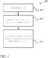
- Figure 4 shows a flow chart diagram illustrating a method 400 according to an embodiment of the present invention.
- the method 400 controls at least one of a dosage device 271 and an engine 201.
- the engine 201 produces an exhaust stream 203 being treated by an exhaust treatment system 250 by use of at least one additive being injected into the exhaust stream 203 by the dosage device 271.
- the additive is injected into an evaporation chamber 280 when being injected into the exhaust stream 203, and the additive is there evaporated.
- the additive is provided to the reduction catalyst device 230 in gaseous form downstream of the dosage device 271 and evaporation chamber 280, which makes the function of the reduction catalyst device 230 efficient.
- the injection of the additive into the evaporation chamber 280 is in figure 3 schematically illustrated as dotted lines.
- the additive may reach/end up at an inner/internal wall 281 inside of the evaporation chamber 280.
- the internal wall 281 of the evaporation chamber 280 may be divided into sections/positions P i along the length of the evaporation chamber 280, i.e. in the flow direction of the exhaust stream 203 flowing through the evaporation chamber 280.
- At least one time dependent condition C i of at least one position P i at an internal wall 281 of the evaporation chamber 280 is determined.
- the at least one time dependent condition C i is determined at least based on at least one interpretation of the internal temperature T i for the at least one position P i , respectively, the at least one representation of the internal temperature T i being determined based on at least one temperature model for the evaporation chamber 280 and one or more of at least one measurement and at least one prediction of an exhaust temperature T exh for the exhaust stream 203 upstream the evaporation chamber 280 in said exhaust treatment system.
- the at least one time dependent condition C i is determined based also on one or more of an exhaust mass flow M exh ⁇ of the exhaust stream 203, and an additive mass flow M add ⁇ being injected by the dosage device 271 into the exhaust stream 203.
- a risk for at least one critical condition C i_critical related to the at least one position P i is determined based on the least one determined time dependent condition C i such that the risk for at least one critical condition C i_critical has a spatial resolution along the internal wall of the evaporation chamber 280.
- the time dependent condition C i may be analyzed to determine for example if there is a risk for formation of additive residues along the internal wall 281, such residues being included in the one or more possible critical conditions C i_critical .
- the one or more possible critical conditions C i_critical is pedagogic reasons often exemplified as including, and/or being related to, creation of residues.
- the present invention is not limited only to residues being the critical conditions C i_citical .
- these one or more possible critical conditions C i_critical may also be related to performance problems for the evaporation chamber 280, i.e. problems resulting in a poor evaporation of the additive, leading to insufficient reduction of nitrogen oxides NO x and/or robustness problems resulting in deposits/residues.
- the risk for e.g. creation of additive residues at the internal wall 281 may generally be increased at lower exhaust temperatures T exh , at lower exhaust mass flow , and at higher additive mass flow M add ⁇ , which is reflected in the determined time dependent condition C i .
- the at least one time dependent condition C i therefore includes the at least one interpretation of the internal temperature T i .
- a third step 430 at least one of the dosage device 271 and the engine 201 is controlled based on the determined risk for at least one critical condition C i_critical .
- the amount of additive being injected into the exhaust stream may for example be decreased if it is determined that there is a high risk C i_critical for forming of additive residues, i.e. if residues are probable to occur.
- the amount of injected additive may be increases, if necessary for achieving an efficient reduction of nitrogen oxides NO x in the downstream at least one arranged reduction catalyst device 230.
- the control 430 of the dosage device 271, which is performed based on the determined risk for at least one critical condition C i_critical . includes control of the additive mass flow M add ⁇ being injected into the exhaust stream 203 and/or control of a time period t add during which the additive is injected into the exhaust stream 203.
- the amount of additive being injected into the exhaust stream 203 is controlled based on the determined critical condition risk C i_critical , e.g. based on the determined risk for additive residues at the internal wall 281 of the evaporation chamber. The more additive being injected, the colder the internal wall 281 gets, since it is cooled down by the additive.
- the amount of injected additive may be reduced, by reducing the additive mass flow M add ⁇ and/or the time period t add for injection of the additive.
- the exhaust temperature T exh for the exhaust stream 203 may be increased and/or the amount of outputted nitrogen oxides NO x may be reduced if it is determined that there is a high risk C i_critical for forming of additive residues, i.e. if residues are probable to occur.
- the temperature T exh for the exhaust stream 203 may be decreased and/or the amount of outputted nitrogen oxides NO x may be increased if it is determined that there is low, or no, risk for forming of residues, whereby the engine may be run more efficiently regarding e.g. fuel consumption if the probability for formation of residues is low.
- the temperature T exh for the exhaust stream 203 and/or the amount of outputted nitrogen oxides NO x may be controlled e.g. by adaption of the engine load/torque and/or the revolutions per minute (RPM) for the engine 201.
- control 430 of the engine 201 which is performed based on the determined risk for at least one critical condition C i_critical , includes a control of at least one injection strategy for the engine 201.
- the timing of fuel injections into the respective cylinders in the engine may be controlled, so that at least the nitrogen oxides NO x output from the engine 201 and/or the temperature T exh of the exhaust stream 203 is controlled. Often, the output nitrogen oxides NO x and/or the temperature T exh of the exhaust stream 203 are relatively easily controlled.
- temperature T exh of the exhaust stream 203 may be controlled to be increased by adjusting the injections in time.
- an injection pressure for an injection of fuel into cylinders of the engine 201 is controlled, whereby at least the nitrogen oxides NO x and/or the exhaust temperature T exh output from the engine 201 is controlled.
- an increase of the exhaust temperature T exh may be performed by adjusting the injection pressure if a risk additive residues is indicated by the at least one critical condition C i_critical .
- an injection phasing for an injection of fuel into cylinders of the engine 201 is controlled. At least the nitrogen oxides NO x and/or the exhaust temperature T exh output from the engine 201 may then be controlled, e.g. for reducing the nitrogen oxides NO x if a risk for additive residues is indicated by the at least one critical condition C i_critical , by adjusting the injection phasing.
- the control 430 of the engine 201 which is performed based on the determined risk for at least one critical condition C i_critical , includes a control of a device for exhaust recirculation (EGR) 211 (schematically illustrated in figure 2 ).
- EGR exhaust recirculation
- the evaporation of the additive is controlled by controlling the exhaust mass flow M exh ⁇ .
- the exhaust mass flow M exh ⁇ may e.g. be controlled if the engine is provided with an exhaust gas recirculation (EGR) device, as described below.
- Combustion engines are supplied with air at an inlet, to achieve a gas mixture which is suitable for combustion, together with fuel that is also supplied to the engine.
- the combustion takes place in the engine's cylinders, wherein the gas mixture is burned.
- the combustion generates exhausts, which leave the engine at an outlet.
- the exhaust recirculation conduit 211 is arranged from the outlet of the engine to its inlet, and leads back a part of the exhausts from the outlet to the inlet.
- An increased exhaust mass flow M exh ⁇ an increased output of nitrogen oxides NO x and/or an increased exhaust temperature T exh may be achieved by decreasing the fraction of the exhaust stream which is recirculated through the EGR device 211.
- an increased exhaust mass flow M exh ⁇ may be useful if a higher risk for additive residues is indicated by the at least one critical condition C i_critical .
- a decreased exhaust mass flow M exh ⁇ may be achieved by increasing the fraction of the exhaust stream, which is recirculated through EGR device 211.
- the control 430 of the dosage device 271 is based also on a maximal allowed time period t add _ max for the at least one time dependent condition C i .
- the maximal allowed time period t add_max indicates a maximal time it is possible to stay in the at least one time dependent condition C i without taking action, such as altering the control of the dosage device 271 and/or altering the control of the engine 201, and still avoid to end up in a critical condition C i_critical .
- the maximal allowed time period t add_max may e.g. be determined based on numerical and/or physical experiments for the evaporation chamber, corresponding to the ones mentioned above for the temperature model.
- the amount of additive to be injected into the exhaust stream may, by use of the present invention, be precisely controlled, such that the evaporation of the injected additive is improved/optimized.
- the at least one time dependent condition C i of at least one position P i may, according to the present invention, be determined based on one or more precise/exact interpretation of the internal temperatures T i related to the potential point of contact P i for the additive with the evaporation chamber wall 281. Also, the determined risk for at least one critical condition C i_critical is then based on the at least one time dependent condition C i , wherefore also the risk for at least one critical condition C i_critical is determined based on this precise/exact interpretation of the internal temperature T i at the internal wall 281 of the evaporation chamber.
- control of the dosage of additive and/or of the engine according to the present invention is very accurate and precise, since it may be based on the very precise/exact interpretation of the internal wall temperature T i .
- control of the dosage of additive and/or of the engine may be performed in an optimized way, e.g. facilitating injecting additive more aggressively into the exhaust stream.
- control of the dosage of additive and/or of the engine may, according to an embodiment of the present invention, include an adjustment of the exhaust mass flow M exh ⁇ and/or of the additive injection mass flow M add ⁇ .
- the spot/location where the additive hits the internal wall 281 of the evaporation chamber is also adjusted/changed/altered, which may be used for reducing the risk for critical conditions, since the area where the additive hits the internal wall may be increased, and since the spot where the additive hits the internal wall may also be changed/controlled. This is e.g. due to the fact that the exhaust mass flow M exh ⁇ and/or the additive injection mass flow M add ⁇ influence where the additive will hit the internal wall 281 of the evaporation chamber.
- a lower exhaust mass flow M exh ⁇ may have the effect that the additive hits the wall closer to the dosage device 271, e.g. in a dotted additive stream line to the left in figure 3 , than for a higher exhaust mass flow M exh ⁇ .
- a higher exhaust mass flow M exh ⁇ would correspondingly result in that the additive hits the internal wall 281 farther away from the dosage device 271, e.g. in a dotted additive stream line to the right in figure 3 .
- the exhaust mass flow M exh ⁇ may be taken into consideration when determining the least one time dependent condition C i , a very reliable determination of the least one time dependent condition C i is provided.
- the exhaust mass flow M exh ⁇ influences where the additive will hit the internal wall 281 of the evaporation chamber. For example, a lower exhaust mass flow M exh ⁇ may have the effect that the additive hits the wall closer to the dosage device 271 than for a higher exhaust mass flow M exh ⁇ . A higher exhaust mass flow M exh ⁇ would correspondingly result in that the additive hits the internal wall 281 farther away from the dosage device 271.
- the at least one time dependent condition C i is determined 410 at least based on at least one interpretation of the internal temperature T i for the at least one internal wall 281 position P i , respectively, an exhaust stream mass flow M exh ⁇ , and/or an additive injection mass flow M add ⁇ .
- the at least one interpretation of the internal temperature T i may be determined in a number of ways.
- the at least one interpretation of the internal temperature T i may be determined dependently or independently of an upcoming/future operation of the engine and/or exhaust treatment system.
- the at least one interpretation of the internal temperature T i is determined based on at least one temperature model for the evaporation chamber 280.
- the at least one interpretation of the internal temperature T i may here be modelled as being embedded in the internal wall 281 of the evaporation chamber 280, i.e. as embedded within the material/castings of the evaporation chamber.
- the at least one interpretation of the internal temperature T i may be modelled as corresponding to the actual temperature at the internal wall 281 where the additive may come in contact with the evaporation chamber, whereby a very exact determination of the risk e.g. for formation of additive residues is achieved.
- the temperature model is used in combination with at least one measurement of an exhaust temperature T exh for the exhaust stream 203 in the exhaust treatment system 250, the measurement being performed by at least one temperature sensor 263 arranged upstream the evaporation chamber 280.
- the upstream 263 measured one or more temperature measurements are input into the temperature model, and the at least one interpretation of the internal temperature T i related to the at least one corresponding position P i at the internal wall 281 is determined. Since the at least one interpretation of the internal temperature T i may be modelled as being embedded within the internal wall 281 of the evaporation chamber, the at least one interpretation of the internal temperature T i may differ from the exhaust temperature T exh of the exhaust stream 203. For example, for temperature transient behavior, e.g.
- the change of the at least one interpretation of the internal temperature T i is faster than the change of the exhaust temperature T exh .
- the change of the at least one interpretation of the internal temperature T i is much slower than the change of the exhaust temperature T exh due to the thermal inertia of the evaporation chamber 280.
- control 430 of the dosage device 271 and/or engine 201 may be based on the determined at least one interpretation of the internal temperature T i and thus may be based not only on the exhaust temperature T exh , a very reliable control 430 may be provided. This is at least partly due to the fact that the control 430 is based on the actual temperature where e.g. additive residues could be created, i.e. is based on the at least one interpretation of the internal temperature T i at the internal wall 281 of the evaporation chamber.
- Known methods have instead based the control of the dosage device only on the exhaust temperature T exh , which results in a much less reliable control, since the exhaust temperature T exh often differs from the at least one interpretation of the internal temperature T i , as explained above.
- the at least one temperature model for the evaporation chamber 280 may also be used in combination with at least one prediction of an exhaust temperature T exh for the exhaust stream 250 in order to determine the at least one interpretation of the internal temperature T i .
- the prediction may e.g. be based on one or more of a number of factors, including for example the torque requested by a driver and/or by a cruise control, on the appearance/features of the road section in which the vehicle is located, and/or the driving style of the driver.
- the at least one interpretation of the internal temperature T i is determined based on a combination of the exhaust temperature T exh upstream the evaporation chamber 280, which may be measured and/or predicted, and a on the at least one internal wall temperature T i_wall , which may be measured e.g. by sensor 265, modelled and/or calculated.
- the temperature model being used for determining the at least one interpretation of the internal temperature T i may use the exhaust temperature T exh for the exhaust stream 203, the exhaust mass flow M exh ⁇ , and/or the additive mass flow M add ⁇ as input parameters.
- the control 430 of the dosage device 271 and/or engine 201 according to the present invention takes into account the cooling effect on the internal wall 281 from the additive being injected, and the cooling effect on the internal wall 281 from the exhausts themselves. These cooling effects are taken into account since the at least one time dependent condition C i may also be based on the exhaust mass flow M exh ⁇ of the exhaust stream 203, and on an injected additive mass flow M add ⁇ .
- control 430 of the dosage device 271 and/or engine 201 according to the present invention may be based on a rather complete information related to a risk for a critical condition, such as e.g. a risk for forming of residues on the internal wall 281.
- the temperature model may for example be determined/defined based on numerical and/or physical experiments. These experiments may then result in an experimental temperature profile T exp_prof having a spatial temperature resolution of at least one experimental position P exp corresponding to the at least one position P i at the internal wall 281 of the evaporation chamber 280.
- the at least one interpretation of the internal temperature T i for the at least one position P i at the internal wall 281 of the evaporation chamber 280 is correlated to the at least one corresponding experimental temperature T exp_ i of the experimental temperature profile T exp _ prof for at least one corresponding experimental position P exp_ i , respectively.
- the at least one interpretation of the internal temperature T i related to the at least one position P i at the internal wall 281 is, according to the model, defined as corresponding to the at least one experimental internal temperature T exp_ i related to the least one corresponding experimental position P exp_ i , respectively.
- the temperature model is determined by injecting, by use of a dosage device 271, differing dosages of the additive into a prototype/physical model of the evaporation chamber 280.
- the prototype/physical model may here at least in size and geometry correspond to an actual evaporation chamber 280 being included in the exhaust treatment system, and may possibly also gave an experimental mass flow corresponding to the exhaust mass flow M exh . flowing through the prototype/physical model.
- the prototype/physical model has at least one experimental position P exp _ i defined as corresponding to the at least one position P i at the evaporation chamber inner wall 281.
- at least one experimental internal temperature T exp_ i related to the at least one experimental position P exp _ i is measured.
- the at least one experimental internal temperature T exp_ i resulting from the actual injection of the additive is measured, respectively.
- the experimental temperature profile T exp _ prof for at least one corresponding experimental position P exp _ i is determined.
- the experimental temperature profile T exp _ prof thus has a spatial temperature resolution with a resolution corresponding to the number of at least one corresponding experimental position P exp_ i .
- the at least one interpretation of the internal temperature T i related to the at least one corresponding position P i at the internal wall 281 is, according to the model, defined as corresponding to the at least one experimental internal temperature T exp_ i related to the least one corresponding experimental position P e xp _ i , respectively.
- the experimental temperature profile T exp _ prof may be determined by injecting differing amounts of additive with the experimental dosage device, and by measuring the resulting one or more experimental internal temperatures T exp _ i related to the one or more corresponding experimental positions P exp_ i along the internal wall 281, for differing operation points of the engine 201.
- At least one experimental cold position P exp_ cold is identified along the internal wall of the prototype/physical model based on the experimental temperature profile T exp_prof .
- At least one cold position P i_cold at the internal wall 281 of the evaporation chamber 280, which corresponds to the at least one experimental cold position P exp_ cold may then be identified.
- T exp_prof it is determined where along the internal wall 281 the additive ends up at the wall, which may be used as an indicator of where along the internal wall 281 there is a potential risk for critical condition to occur.
- the hereby identified at least one cold position P i_cold is determined as being at least one position related to which, i.e.
- the risk for the at least one critical condition C i_critical may be increased.
- the deposits/residues are formed/created downstream adjacent to the at least one cold position P i _ cold , where the temperature is slightly higher than in the at least one cold position P i_cold .
- T exp_prof the experimental temperature profile
- This at least one experimental cold position P exp _cold has at least one corresponding cold position P i_cold in the evaporation chamber 280.
- the experimental temperature profile T exp_prof and/or one or more experimental internal temperatures T exp_ i for the one or more corresponding experimental positions P exp_ i along the internal wall 281 are at least partly predicted/calculated.
- the at least one time dependent condition C i is determined 410 based on at least one interpretation of the internal temperature T i related to the at least one internal wall position P i , respectively, an exhaust stream mass flow M exh . , and/or an additive injection mass flow M add . .
- the at least one interpretation of the internal temperature T i may, according to an embodiment of the present invention, be determined based also on at least one measurement of the at least one internal temperature T i performed by at least one internal temperature sensor 265 (shown in figure 3 ) arranged at the at least one position P i at the internal wall 281 of the evaporation chamber 280.
- the at least one internal temperature sensor 265 is embedded in the internal wall 281, i.e. is embedded within the material/castings of the internal wall 281.
- the evaporation chamber may be at least partly heated by use of a heating device.
- the heating device is then arranged for increasing the temperature of one or more sections of the evaporation chamber.
- the herein described representation of the internal temperature T i and/or the herein determination of the representation of the internal temperature T i is then influenced by this heating of the evaporation chamber.
- the herein described at least one temperature model may then be based also on the provided heat/increase temperature, i.e. the at least one temperature model may take added heat into consideration.
- the at least one time dependent condition C i is determined 410 based, among other input, on at least the exhaust stream mass flow M exh . .
- This exhaust stream mass flow M exh . may be determined in a number of ways.
- the exhaust stream mass flow M exh . may be determined based on at least one mass flow model for the exhaust treatment system 250. This model may take into account e.g. the physical form and dimension of the exhaust treatment system and/or an operation mode for the engine 201 producing the exhaust stream 203.
- the exhaust stream mass flow M exh . may also be determined based an amount of fuel and an amount of air being input into the cylinders of the engine 201 producing the exhaust stream 203. Thus, based on the air and fuel being input into the cylinders, a resulting exhaust stream mass flow M exh . may be calculated, which may be used when determining the at least one time dependent condition C i .
- the exhaust stream mass flow M exh . may also be determined based on at least one measurement of the exhaust mass flow M exh . for the exhaust stream 203. This measurement may e.g. be performed by at least one mass flow sensor 263 arranged upstream the evaporation chamber 280 in the exhaust treatment system 250.
- the at least one time dependent condition C i is related to a mass M add_wall of additive being present at the at least one position P i at the internal wall 281 of the evaporation chamber 280.
- a mass M add_wall of additive gathering i.e. a concentration of additive
- a mass M add _ wall of additive being present at the at least one position P i at the internal wall 281 could under certain conditions be interpreted as being a risk for at least one critical condition C i_critical , i.e. for additive residues, related to the at least one position P i .
- the mass M add_wall of additive present at the internal wall 281 may be determined/estimated based on the at least one interpretation of the internal temperature T i , the injected additive mass flow M add ⁇ , the exhaust mass flow M exh ⁇ and/or an injection time period t add .
- the amount of additive being injected and/or the at least one interpretation of the internal temperature T i may be used for determining the mass M add_wall of additive present at the internal wall 281.
- the forming of mass Ma dd_wall of additive present at the internal wall 281 may further be determined/defined based on numerical and/or physical experiments for the evaporation chamber, corresponding to the ones mentioned above for the temperature model.
- the determination 420 of the risk for at least one critical condition C i_critical occurring related to the at least one position P i is determined based also on an exhaust temperature T exh for the exhaust stream 203 upstream the evaporation chamber 280, e.g. measured by an upstream temperature sensor 263 in the exhaust treatment system 250.
- T exh exhaust temperature
- M add_wall of additive being present at the internal wall 281 for the same amounts of additive being injected into the exhaust stream 203.
- the risk for forming residues is lower than for lower exhaust temperatures T exh, i.e.
- the risk for ending up in at least one critical condition C i_critical is lower. This also means that more additive may be injected into the exhaust stream 203 if the exhaust temperature T exh is higher, without risk for reaching at least one critical condition C i_critical , than for lower exhaust temperatures T exh .
- the determination 420 of the risk for at least one critical condition C i_critical occurring related to the at least one position P i may be determined based also on the exhaust mass flow M exh ⁇ for the exhaust stream.
- the at least one time dependent condition C i is determined at least partly based on one or more simulations of future/upcoming engine conditions for a road section ahead of the vehicle.
- the simulations may conducted such that they are based on the current position and situation of the vehicle and looks forward over the road section, wherein the simulations may be made on the basis of e.g. a road slope for the road section.
- the road section can also be seen as a horizon ahead of the vehicle, for which the simulation is to be conducted.
- the simulation may also be based on one or more of e.g.
- the road section information may be obtained in a number of different ways.
- the information regarding the upcoming road section e.g. the road slope, may be determined on the basis of map data, for example from digital maps comprising topographical information, in combination with positioning information, such as, for example GPS information (Global Positioning System). With the aid of the positioning information, the position of the vehicle in relation to the map data can be established, so that e.g. the road slope can be extracted from the map data.
- GPS information Global Positioning System
- map data and positioning information are utilized. Such systems can then provide map data and positioning information to the system for the present invention, the effect of which is that the added complexity for the determination of the road section information is minimized.
- the information of the upcoming road section, e.g. the road slope, on which the simulations are based can also be obtained by estimating e.g. the road slope encountered by the vehicle in the simulation instance.
- this road slope for example on the basis of an engine torque in the vehicle, of an acceleration for the vehicle, on an accelerometer, on GPS information, on radar information, on camera information, on information from another vehicle, on positioning information and road slope information stored earlier in the vehicle, or on information obtained from a traffic system related to said road section.
- road section information estimated by one vehicle can also be made available to other vehicles, either directly, or via an intermediate unit such as a database or the like.
- a method for controlling a dosage device and/or an engine according to the present invention may also be implemented in a computer program, which when executed in a computer will cause the computer to execute the method.
- the computer program usually forms a part of a computer program product 503, wherein the computer program product comprises a suitable digital nonvolatile/permanent/persistent/durable storage medium on which the computer program is stored.
- the nonvolatile/permanent/persistent/durable computer readable medium includes a suitable memory, e.g.: ROM (Read-Only Memory), PROM (Programmable Read-Only Memory), EPROM (Erasable PROM), Flash, EEPROM (Electrically Erasable PROM), a hard disk device, etc.
- ROM Read-Only Memory
- PROM PROM
- EPROM Erasable PROM
- Flash Flash
- EEPROM Electrical Erasable PROM
- a hard disk device etc.
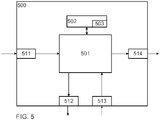
- FIG. 5 schematically shows a control device/means 500.
- the control device/means 500 comprises a calculation unit 501, which may include essentially a suitable type of processor or microcomputer, e.g. a circuit for digital signal processing (Digital Signal Processor, DSP), or a circuit with a predetermined specific function (Application Specific Integrated Circuit, ASIC).
- the calculation unit 501 is connected to a memory unit 502, installed in the control device/means 500, providing the calculation device 501 with e.g. the stored program code and/or the stored data, which the calculation device 501 needs in order to be able to carry out calculations.
- the calculation unit 501 is also set up to store interim or final results of calculations in the memory unit 502.
- control device/means 500 is equipped with devices 511, 512, 513, 514 for receiving and sending of input and output signals, respectively.
- These input and output signals may contain wave shapes, pulses, or other attributes, which may be detected as information by the devices 511, 513 for the receipt of input signals, and may be converted into signals that may be processed by the calculation unit 501. These signals are then provided to the calculation unit 501.
- the devices 512, 514 for sending output signals are arranged to convert the calculation result from the calculation unit 501 into output signals for transfer to other parts of the vehicle's control system, and/or the component(s) for which the signals are intended.
- Each one of the connections to the devices for receiving and sending of input and output signals may include one or several of a cable; a data bus, such as a CAN (Controller Area Network) bus, a MOST (Media Oriented Systems Transport) bus, or any other bus configuration; or of a wireless connection.
- a data bus such as a CAN (Controller Area Network) bus, a MOST (Media Oriented Systems Transport) bus, or any other bus configuration
- a wireless connection such as a Wi-Fi
- control systems in modern vehicles include of a communications bus system, comprising one or several communications buses to connect a number of electronic control devices (ECUs), or controllers, and different components localised on the vehicle.
- ECUs electronice control devices
- Such a control system may comprise a large number of control devices, and the responsibility for a specific function may be distributed among more than one control device.
- Vehicles of the type shown thus often comprise significantly more control devices than what is shown in figures 1 , 2 , 3 and 5 , which is well known to a person skilled in the art within the technology area.
- control device/means 500 in figure 5 may comprise and/or illustrate one or several of the control devices/systems/means 215 and 260 in figure 1 , the control devices/systems/means 215, 260, 290 in figure 2 , or the control devices/systems/means 215, 260, 290 in figure 3 .
- the control device/means 290 in figures 2 and 3 is arranged for performing the present invention.
- the units/means 291, 292, 293 may for example correspond to groups of instructions, which can be in the form of programming code, that are input into, and are utilized by a processor when the units are active and/or are utilized for performing its method step, respectively.
- the present invention in the embodiment shown, may be implemented in the control device/menas 500.
- the invention may, however, also be implemented wholly or partly in one or several other control devices, already existing in the vehicle, or in a control device dedicated to the present invention.
- a system 200 arranged for controlling at least one of a dosage device 271 and an engine 201 is disclosed.
- the exhaust stream 203 is produced by an engine 201, and is then treated by an exhaust treatment system 250 including e.g. a reduction catalyst device.
- At least one additive is injected into the exhaust stream 203 by the dosage device 271, and is evaporated in an evaporation chamber 280 when being injected into the exhaust stream 203.
- the system 200 includes a first determination unit 291, which is arranged for determining 410 at least one time dependent condition C i of at least one position P i at an internal wall 281 of the evaporation chamber 280.
- the determination unit 291 is arranged for determining the at least one time dependent condition C i at least based on at least one interpretation of the internal temperature T i related to the at least one position P i , respectively, the at least one representation of the internal temperature T i being determined based on at least one temperature model for the evaporation chamber 280 and one or more of at least one measurement and at least one prediction of an exhaust temperature T exh for the exhaust stream 203 upstream the evaporation chamber 280 in the exhaust treatment system 250.
- the at least one time dependent condition C i is determined based also on one or more of an exhaust mass flow M exh ⁇ of the exhaust stream 203, and an additive mass flow M add ⁇ being injected by the dosage device 271 into the exhaust stream 203.
- the determination unit 291 may be arranged for performing any above described embodiment related to the determination of at least one time dependent condition C i .
- the system 200 also includes a second determination unit 292, which is arranged for determining 420 a risk for at least one critical condition C i_critical occurring related to the at least one position P i based on the least one time dependent condition C i determined by the first determination unit 291, such that the risk for at least one critical condition C i_critical has a spatial resolution along the internal wall of the evaporation chamber 280.
- the second determination unit 292 may be arranged for performing any above described embodiment related to the determination of the risk for at least one critical condition C i_critical of occur.
- the system 200 further includes a control unit 293, which is arranged for controlling 430 at least one of the dosage device 271 and the engine 201 based on the risk for at least one critical condition C i_critical being determined by the second determination unit 292.
- the control unit 293 may be arranged for performing any above mentioned control of the dosage device 271 and/or of the engine 201.
- the system 200 may thus be arranged/modified for performing any of the in this document described embodiments of the method according to the present invention.
- the exhaust treatment system 250 shown in figures 2 and 3 includes only one dosage device 271, only one reduction catalyst device 230, and only one evaporation chamber 280 for pedagogic reasons. It should, however, be noted that the present invention is not restricted to such systems, and may instead be generally applicable in any exhaust treatment system including one or more dosage devices, one or more reduction catalyst devices, and one or more evaporation chambers. For example, the present invention is especially applicable on systems including a first dosage device, a first evaporation chamber, a first reduction catalyst device, a second dosage device, a second evaporation chamber and a second reduction catalyst device.
- Each one of the first and second reduction catalyst devices may include at least one SCR-catalyst, at least one ammonia slip catalyst ASC, and/or at least one multifunctional slip-catalyst SC.
- the multifunctional slip catalyst SC may be arranged primarily for reduction of nitrogen oxides NO x , and secondarily for oxidation of additive in the exhaust stream.
- the multifunctional slip catalyst SC may also be arranged for performing at least some of the functions normally performed by a DOC, e.g. oxidation of hydrocarbons C x H y (also referred to as HC) and carbon monoxide CO in the exhaust stream 203 into carbon dioxide CO 2 and water H 2 O and/or oxidation of nitrogen monoxides NO occurring in the exhaust stream into nitrogen dioxide NO 2 .
- a DOC e.g. oxidation of hydrocarbons C x H y (also referred to as HC) and carbon monoxide CO in the exhaust stream 203 into carbon dioxide CO 2 and water H 2 O and/or
- the present invention is also related to a vehicle 100, such as e.g. a truck, a bus or a car, including the herein described system 200 for arranged for controlling a dosage device 271 and/or an engine 201.
- vehicle 100 such as e.g. a truck, a bus or a car
- system 200 for arranged for controlling a dosage device 271 and/or an engine 201.
- inventive method, and embodiments thereof, as described above may at least in part be performed with/using/by at least one device.
- the inventive method, and embodiments thereof, as described above may be performed at least in part with/using/by at least one device that is suitable and/or adapted for performing at least parts of the inventive method and/or embodiments thereof.
- a device that is suitable and/or adapted for performing at least parts of the inventive method and/or embodiments thereof may be one, or several, of a control unit, an electronic control unit (ECU), an electronic circuit, a computer, a computing unit and/or a processing unit.
- ECU electronice control unit
- inventive method and embodiments thereof, as described above, may be referred to as an, at least in part, computerised method.
- Said method being, at least in part, computerised meaning that it is performed at least in part with/using/by said at least one device that is suitable and/or adapted for performing at least parts of the inventive method and/or embodiments thereof.
- inventive method and embodiments thereof, as described above, may be referred to as an, at least in part, automated method.
- Said method being, at least in part, automated meaning that it is performed with/using/by said at least one device that is suitable and/or adapted for performing at least parts of the inventive method and/or embodiments thereof.
Landscapes
- Engineering & Computer Science (AREA)
- Chemical & Material Sciences (AREA)
- Chemical Kinetics & Catalysis (AREA)
- Combustion & Propulsion (AREA)
- Mechanical Engineering (AREA)
- General Engineering & Computer Science (AREA)
- Health & Medical Sciences (AREA)
- Toxicology (AREA)
- Analytical Chemistry (AREA)
- Biomedical Technology (AREA)
- Environmental & Geological Engineering (AREA)
- General Chemical & Material Sciences (AREA)
- Oil, Petroleum & Natural Gas (AREA)
- Exhaust Gas After Treatment (AREA)
- Combined Controls Of Internal Combustion Engines (AREA)
- Medicinal Preparation (AREA)
Claims (14)
- Verfahren (400) zum Steuern einer Dosiervorrichtung (271) und/oder eines Motors (201), wobei der Motor (201) einen Abgasstrom (203) erzeugt, der durch ein Abgasbehandlungssystem (250) unter Verwendung eines von der Dosiervorrichtung (271) in den Abgasstrom (203) eingespritzten Additivs behandelt wird, wobei das Additiv dazu bestimmt ist, in einer Verdampfungskammer (280) verdampft zu werden, wenn es in den Abgasstrom (203) eingespritzt wird, wobei das Verfahren umfasst:- Bestimmen (410) eines zeitabhängigen Zustands Ci einer Position Pi an einer Innenwand (281) der Verdampfungskammer (280),wobei der zeitabhängige Zustand Ci auf der Grundlage einer Darstellung einer Innentemperatur Ti in Bezug auf die Position Pi bestimmt wird,wobei die Darstellung der Innentemperatur Ti auf der Grundlage eines Temperaturmodells für die Verdampfungskammer (280) bestimmt wird und:einer Messung einer Abgastemperatur Texh für den Abgasstrom (203) stromaufwärts der Verdampfungskammer (280) in dem Abgasbehandlungssystem (250) und/odereiner Vorhersage einer Abgastemperatur Texh für den Abgasstrom (203) stromaufwärts der Verdampfungskammer (280) in dem Abgasbehandlungssystem (250);- Bestimmen (420) eines Risikos eines kritischen Zustands Ci_citical in Bezug auf die Position Pi auf der Grundlage des bestimmten zeitabhängigen Zustands Ci , sodass das Risiko eines kritischen Zustands Ci_citical eine räumliche Auflösung entlang der Innenwand der Verdampfungskammer (280) aufweist, und- Steuern (430) der Dosiervorrichtung (271) und/oder des Motors (201) auf der Grundlage des bestimmten Risikos eines kritischen Zustand Ci_critical.
- Verfahren (400) nach Anspruch 1, wobei die Darstellung der Innentemperatur Ti auch auf der Grundlage einer Messung der Innentemperatur, die von einem an der Position Pi an der Innenwand (281) der Verdampfungskammer (280) angeordneten Innentemperatursensor (265) durchgeführt wird, als eine Kombination aus der Abgastemperatur Texh für den Abgasstrom (203) und einer Innenwandtemperatur Ti_wall bestimmt wird; Ti = x * Ti_wall + y * Texh.
- Verfahren (400) nach Anspruch 2, wobei das Temperaturmodell die Abgastemperatur Texh für den Abgasstrom (203), einen Abgasmassenstrom Mexh und einen in den Abgasstrom (203) eingespritzten Additivmassenstrom Madd als Eingangsparameter verwendet.
- Verfahren (400) nach einem der Ansprüche 2 bis 3, wobei- das Temperaturmodell durch numerische und/oder physikalische Experimente bestimmt wird, die jeweils zu einem experimentellen Temperaturprofil Texp _prof führen mit einer räumlichen Temperaturauflösung einer experimentellen Position Pexp, die der Position Pi der Verdampfungskammer (280) entspricht; und- die Darstellung der Innentemperatur Ti für die Position Pi der Verdampfungskammer (280) einer experimentellen Temperatur T exp _i des experimentellen Temperaturprofils Texp_prof für eine entsprechende experimentelle Position P exp_i entspricht.
- Verfahren (400) nach Anspruch 4, wobei- eine experimentelle Kälteposition P exp_cold des experimentellen Temperaturprofils Texp _prof auf der Grundlage des experimentellen Temperaturprofils Texp _prof festgestellt wird und- eine Kälteposition Pi_cold an der Innenwand (281) der Verdampfungskammer (280) als eine Position bestimmt wird, die mit einem erhöhten Risiko eines kritischen Zustands Ci_critical verbunden ist, wobei die Kälteposition Pi_cold derart bestimmt wird, dass sie der experimentellen Kälteposition P exp_cold entspricht.
- Verfahren (400) nach einem der Ansprüche 1 bis 5, wobei der zeitabhängige Zustand Ci auch auf der Grundlage eines oder mehrerer der folgenden Elemente bestimmt wird: Abgasmassenstrom Mexh des Abgasstroms (203) und von der Dosiervorrichtung (271) in den Abgasstrom (203) eingespritzter Additivmassenstrom Madd.
- Verfahren (400) nach Anspruch 6, wobei der Abgasmassenstrom Mexh auf der Grundlage von wenigstens einem Element der folgenden Gruppen bestimmt wird:- einem Massenstrommodell für das Abgasbehandlungssystem (250);- einer Kraftstoffmenge und einer Luftmenge, die den Zylindern des Motors (201) zugeführt werden; und- einer Messung des Abgasmassenstroms Mexh für den Abgasstrom (203), die von einem Massenstromsensor (263) durchgeführt wird, der stromaufwärts der Verdampfungskammer (280) in dem Abgasbehandlungssystem (250) angeordnet ist.
- Verfahren (400) nach einem der Ansprüche 1-7, wobei der wenigstens eine zeitabhängige Zustand Ci mit einer Masse Madd_wall des Additivs zusammenhängt, die an der wenigstens einen Position Pi an der Innenwand (281) der Verdampfungskammer (280) vorhanden ist.
- Verfahren (400) nach Anspruch 8, wobei die Masse Madd_wall des Additivs auf der Grundlage eines oder mehrerer der folgenden Elemente bestimmt wird:
Darstellung der Innentemperatur Ti , wobei der Additivmassenstrom Madd in den Abgasstrom (203) eingespritzt wird, Abgasmassenstrom Mexh für den Abgasstrom (203) und Zeitdauer tadd , während der das Additiv in den Abgasstrom (203) eingespritzt wird. - Verfahren (400) nach einem der Ansprüche 1 bis 9, wobei die Steuerung (430) der Dosiervorrichtung (271) die Steuerung eines oder mehrerer Elemente der folgenden Gruppen umfasst:- eines Additivmassenstroms Madd , der in den Abgasstrom (203) eingespritzt wird; und- einer Zeitdauer tadd , während der das Additiv in den Abgasstrom (203) eingespritzt wird.
- Verfahren (400) nach einem der Ansprüche 1 bis 10, wobei die Steuerung (430) des Motors (201) die Steuerung eines oder mehrerer Elemente der folgenden Gruppen umfasst:- Steuerung einer Einspritzstrategie für den Motor (201);- Steuerung eines Zeitpunkts für eine Kraftstoffeinspritzung in die Zylinder des Motors (201);- Steuerung eines Einspritzdrucks für eine Kraftstoffeinspritzung in die Zylinder des Motors (201);- Steuerung einer Einspritzphaseneinstellung für eine Kraftstoffeinspritzung in die Zylinder des Motors (201); und- Steuerung einer Abgasrückführungsvorrichtung (AGR; 211).
- Computerprogramm mit Befehlen, die, wenn das Programm von einem Computer ausgeführt wird, den Computer veranlassen, das Verfahren nach einem der Ansprüche 1-11 auszuführen.
- Computerlesbares Medium mit Befehlen, die, wenn das Programm nach Anspruch 12 von einem Computer ausgeführt wird, den Computer veranlassen, das Verfahren nach einem der Ansprüche 1-11 auszuführen.
- System (200) zum Steuern einer Dosiervorrichtung (271) und/oder eines Motors (201), wobei der Motor (201) einen Abgasstrom (203) erzeugt, der durch ein Abgasbehandlungssystem (250) unter Verwendung eines von der Dosiervorrichtung (271) in den Abgasstrom (203) eingespritzten Additivs behandelt wird, wobei das Additiv dazu bestimmt ist, in einer Verdampfungskammer (280) verdampft zu werden, wenn es in den Abgasstrom (203) eingespritzt wird, wobei das System umfasst:- Einrichtung (291) zum Bestimmen (410) eines zeitabhängigen Zustands Ci einer Position Pi an einer Innenwand (281) der Verdampfungskammer (280),wobei die Einrichtung (291) angeordnet ist zum Bestimmen des zeitabhängigen Zustands Ci auf der Grundlage einer Darstellung einer Innentemperatur Ti in Bezug auf die Position Pi ,wobei die Darstellung der Innentemperatur Ti auf der Grundlage eines Temperaturmodells für die Verdampfungskammer (280) bestimmt wird und:einer Messung einer Abgastemperatur Texh für den Abgasstrom (203) stromaufwärts der Verdampfungskammer (280) in dem Abgasbehandlungssystem (250) und/odereiner Vorhersage einer Abgastemperatur Texh für den Abgasstrom (203) stromaufwärts der Verdampfungskammer (280) in dem Abgasbehandlungssystem (250);- Einrichtung (292) zum Bestimmen (420) eines Risikos eines kritischen Zustands Ci_critical in Bezug auf die Position Pi auf der Grundlage des bestimmten zeitabhängigen Zustands Ci , sodass das Risiko eines kritischen Zustands Ci_citical eine räumliche Auflösung entlang der Innenwand der Verdampfungskammer (280) aufweist; und- Einrichtung (293) zum Steuern (430) der Dosiervorrichtung (271) und/oder des Motors (201) auf der Grundlage des bestimmten Risikos eines kritischen Zustand Ci_critical ;
Steuereinheit (290), die die Einrichtungen (291, 292, 293) umfasst.
Applications Claiming Priority (2)
| Application Number | Priority Date | Filing Date | Title |
|---|---|---|---|
| SE1750393A SE540842C2 (en) | 2017-03-31 | 2017-03-31 | Method and system for control of at least one of a dosage device and an engine |
| PCT/SE2018/050306 WO2018182486A1 (en) | 2017-03-31 | 2018-03-23 | Method and system for control of at least one of a dosage device and an engine |
Publications (3)
| Publication Number | Publication Date |
|---|---|
| EP3601759A1 EP3601759A1 (de) | 2020-02-05 |
| EP3601759A4 EP3601759A4 (de) | 2020-08-19 |
| EP3601759B1 true EP3601759B1 (de) | 2022-05-04 |
Family
ID=63676717
Family Applications (1)
| Application Number | Title | Priority Date | Filing Date |
|---|---|---|---|
| EP18777216.5A Active EP3601759B1 (de) | 2017-03-31 | 2018-03-23 | Verfahren und system zur steuerung mindestens einer dosiervorrichtung und/oder eines motors |
Country Status (4)
| Country | Link |
|---|---|
| US (1) | US20200049047A1 (de) |
| EP (1) | EP3601759B1 (de) |
| SE (1) | SE540842C2 (de) |
| WO (1) | WO2018182486A1 (de) |
Families Citing this family (1)
| Publication number | Priority date | Publication date | Assignee | Title |
|---|---|---|---|---|
| EP4303410B1 (de) | 2022-07-04 | 2025-05-07 | Volvo Truck Corporation | Harnstoffkristalldetektion durch überwachen eines verhältnisses zwischen einem nox-sensorsignal und einem äquivalenzverhältnis |
Family Cites Families (7)
| Publication number | Priority date | Publication date | Assignee | Title |
|---|---|---|---|---|
| DE102005031720B4 (de) * | 2005-07-07 | 2020-06-18 | Daimler Ag | Verfahren zur Dosierung eines Reduktionsmittels |
| US8061123B2 (en) * | 2007-10-30 | 2011-11-22 | Caterpillar Inc. | Method and system of thermal management in an exhaust system |
| KR101282220B1 (ko) * | 2008-05-27 | 2013-07-09 | 퓨얼 테크 인코포레이티드 | 암모니아 함유 가스를 형성하기 위해 개선된 요소의 기화를 제공하는 선택적 촉매 NOx 환원 방법 및 장치 |
| EP3444460B1 (de) * | 2009-12-21 | 2019-11-13 | Cummins IP, Inc. | Vorrichtung, system und verfahren zur milderung von ablagerungen einer 32-prozentigen wässrigen harnstofflösung und zugehöriger zustände |
| US20140000247A1 (en) * | 2011-03-14 | 2014-01-02 | International Engine Intellectual Property Company Llc | Model-based system and method for mitigating diesel emission fluid deposits |
| JP5796777B2 (ja) * | 2011-12-12 | 2015-10-21 | 三菱ふそうトラック・バス株式会社 | 内燃機関の排ガス浄化装置及び尿素の堆積検出方法 |
| FR3023318B1 (fr) * | 2014-07-07 | 2016-07-22 | Peugeot Citroen Automobiles Sa | Procede de limitation d'un encrassement d'un mixeur. |
-
2017
- 2017-03-31 SE SE1750393A patent/SE540842C2/en unknown
-
2018
- 2018-03-23 WO PCT/SE2018/050306 patent/WO2018182486A1/en not_active Ceased
- 2018-03-23 EP EP18777216.5A patent/EP3601759B1/de active Active
- 2018-03-23 US US16/495,621 patent/US20200049047A1/en not_active Abandoned
Also Published As
| Publication number | Publication date |
|---|---|
| SE540842C2 (en) | 2018-11-27 |
| US20200049047A1 (en) | 2020-02-13 |
| EP3601759A1 (de) | 2020-02-05 |
| WO2018182486A1 (en) | 2018-10-04 |
| SE1750393A1 (en) | 2018-10-01 |
| EP3601759A4 (de) | 2020-08-19 |
Similar Documents
| Publication | Publication Date | Title |
|---|---|---|
| US10260392B2 (en) | Method and system for controlling nitrogen oxide emissions from a combustion engine | |
| EP3551858B1 (de) | Verfahren und system zur steuerung eines ammoniakabdeckungsgradprofils | |
| US20180128197A1 (en) | Systems and methods for non-intrusive closed-loop combustion control of internal combustion engines | |
| EP3341597B1 (de) | Verfahren und vorrichtung zur behandlung eines abgasstroms | |
| EP3784886B1 (de) | Verfahren und system zur steuerung einer aktivierung von mindestens einem flüssigkeitssensitiven sensor | |
| EP3601759B1 (de) | Verfahren und system zur steuerung mindestens einer dosiervorrichtung und/oder eines motors | |
| CN109209588A (zh) | 用于调整燃烧以缓解排气过温的系统和方法 | |
| EP3784885B1 (de) | Verfahren und steuersystem zur steuerung der dosierung eines reduktionsmittels | |
| US9784165B2 (en) | Method of operating an aftertreatment system of an internal combustion engine | |
| WO2019209162A1 (en) | Method and system for determination of and for reduction of a risk for formation of solid deposits | |
| EP3073084A1 (de) | Abgasnachbehandlungsgerät für eine verbrennungsmaschine und methode für ein abgasnachbehandlungsgerät | |
| SE1350993A1 (sv) | Förfarande och system för reglering av en förbränningsmotor |
Legal Events
| Date | Code | Title | Description |
|---|---|---|---|
| STAA | Information on the status of an ep patent application or granted ep patent |
Free format text: STATUS: THE INTERNATIONAL PUBLICATION HAS BEEN MADE |
|
| PUAI | Public reference made under article 153(3) epc to a published international application that has entered the european phase |
Free format text: ORIGINAL CODE: 0009012 |
|
| STAA | Information on the status of an ep patent application or granted ep patent |
Free format text: STATUS: REQUEST FOR EXAMINATION WAS MADE |
|
| 17P | Request for examination filed |
Effective date: 20191031 |
|
| AK | Designated contracting states |
Kind code of ref document: A1 Designated state(s): AL AT BE BG CH CY CZ DE DK EE ES FI FR GB GR HR HU IE IS IT LI LT LU LV MC MK MT NL NO PL PT RO RS SE SI SK SM TR |
|
| AX | Request for extension of the european patent |
Extension state: BA ME |
|
| DAV | Request for validation of the european patent (deleted) | ||
| DAX | Request for extension of the european patent (deleted) | ||
| A4 | Supplementary search report drawn up and despatched |
Effective date: 20200717 |
|
| RIC1 | Information provided on ipc code assigned before grant |
Ipc: F01N 3/28 20060101ALI20200713BHEP Ipc: F01N 9/00 20060101AFI20200713BHEP Ipc: F01N 3/20 20060101ALI20200713BHEP |
|
| GRAP | Despatch of communication of intention to grant a patent |
Free format text: ORIGINAL CODE: EPIDOSNIGR1 |
|
| RAP3 | Party data changed (applicant data changed or rights of an application transferred) |
Owner name: SCANIA CV AB |
|
| STAA | Information on the status of an ep patent application or granted ep patent |
Free format text: STATUS: GRANT OF PATENT IS INTENDED |
|
| GRAJ | Information related to disapproval of communication of intention to grant by the applicant or resumption of examination proceedings by the epo deleted |
Free format text: ORIGINAL CODE: EPIDOSDIGR1 |
|
| INTG | Intention to grant announced |
Effective date: 20210429 |
|
| RIN1 | Information on inventor provided before grant (corrected) |
Inventor name: TEMPELMANN, DAVID Inventor name: ORRLING, STEFAN Inventor name: BIRGERSSON, HENRIK |
|
| STAA | Information on the status of an ep patent application or granted ep patent |
Free format text: STATUS: REQUEST FOR EXAMINATION WAS MADE |
|
| INTC | Intention to grant announced (deleted) | ||
| GRAP | Despatch of communication of intention to grant a patent |
Free format text: ORIGINAL CODE: EPIDOSNIGR1 |
|
| STAA | Information on the status of an ep patent application or granted ep patent |
Free format text: STATUS: GRANT OF PATENT IS INTENDED |
|
| GRAJ | Information related to disapproval of communication of intention to grant by the applicant or resumption of examination proceedings by the epo deleted |
Free format text: ORIGINAL CODE: EPIDOSDIGR1 |
|
| STAA | Information on the status of an ep patent application or granted ep patent |
Free format text: STATUS: REQUEST FOR EXAMINATION WAS MADE |
|
| INTG | Intention to grant announced |
Effective date: 20210804 |
|
| INTC | Intention to grant announced (deleted) | ||
| GRAP | Despatch of communication of intention to grant a patent |
Free format text: ORIGINAL CODE: EPIDOSNIGR1 |
|
| STAA | Information on the status of an ep patent application or granted ep patent |
Free format text: STATUS: GRANT OF PATENT IS INTENDED |
|
| GRAJ | Information related to disapproval of communication of intention to grant by the applicant or resumption of examination proceedings by the epo deleted |
Free format text: ORIGINAL CODE: EPIDOSDIGR1 |
|
| STAA | Information on the status of an ep patent application or granted ep patent |
Free format text: STATUS: REQUEST FOR EXAMINATION WAS MADE |
|
| GRAP | Despatch of communication of intention to grant a patent |
Free format text: ORIGINAL CODE: EPIDOSNIGR1 |
|
| STAA | Information on the status of an ep patent application or granted ep patent |
Free format text: STATUS: GRANT OF PATENT IS INTENDED |
|
| INTG | Intention to grant announced |
Effective date: 20211102 |
|
| INTC | Intention to grant announced (deleted) | ||
| INTG | Intention to grant announced |
Effective date: 20211201 |
|
| GRAS | Grant fee paid |
Free format text: ORIGINAL CODE: EPIDOSNIGR3 |
|
| GRAA | (expected) grant |
Free format text: ORIGINAL CODE: 0009210 |
|
| STAA | Information on the status of an ep patent application or granted ep patent |
Free format text: STATUS: THE PATENT HAS BEEN GRANTED |
|
| AK | Designated contracting states |
Kind code of ref document: B1 Designated state(s): AL AT BE BG CH CY CZ DE DK EE ES FI FR GB GR HR HU IE IS IT LI LT LU LV MC MK MT NL NO PL PT RO RS SE SI SK SM TR |
|
| REG | Reference to a national code |
Ref country code: GB Ref legal event code: FG4D |
|
| REG | Reference to a national code |
Ref country code: CH Ref legal event code: EP |
|
| REG | Reference to a national code |
Ref country code: AT Ref legal event code: REF Ref document number: 1489247 Country of ref document: AT Kind code of ref document: T Effective date: 20220515 |
|
| REG | Reference to a national code |
Ref country code: IE Ref legal event code: FG4D Ref country code: DE Ref legal event code: R096 Ref document number: 602018035032 Country of ref document: DE |
|
| REG | Reference to a national code |
Ref country code: LT Ref legal event code: MG9D |
|
| REG | Reference to a national code |
Ref country code: NL Ref legal event code: MP Effective date: 20220504 |
|
| REG | Reference to a national code |
Ref country code: AT Ref legal event code: MK05 Ref document number: 1489247 Country of ref document: AT Kind code of ref document: T Effective date: 20220504 |
|
| PG25 | Lapsed in a contracting state [announced via postgrant information from national office to epo] |
Ref country code: SE Free format text: LAPSE BECAUSE OF FAILURE TO SUBMIT A TRANSLATION OF THE DESCRIPTION OR TO PAY THE FEE WITHIN THE PRESCRIBED TIME-LIMIT Effective date: 20220504 Ref country code: PT Free format text: LAPSE BECAUSE OF FAILURE TO SUBMIT A TRANSLATION OF THE DESCRIPTION OR TO PAY THE FEE WITHIN THE PRESCRIBED TIME-LIMIT Effective date: 20220905 Ref country code: NO Free format text: LAPSE BECAUSE OF FAILURE TO SUBMIT A TRANSLATION OF THE DESCRIPTION OR TO PAY THE FEE WITHIN THE PRESCRIBED TIME-LIMIT Effective date: 20220804 Ref country code: NL Free format text: LAPSE BECAUSE OF FAILURE TO SUBMIT A TRANSLATION OF THE DESCRIPTION OR TO PAY THE FEE WITHIN THE PRESCRIBED TIME-LIMIT Effective date: 20220504 Ref country code: LT Free format text: LAPSE BECAUSE OF FAILURE TO SUBMIT A TRANSLATION OF THE DESCRIPTION OR TO PAY THE FEE WITHIN THE PRESCRIBED TIME-LIMIT Effective date: 20220504 Ref country code: HR Free format text: LAPSE BECAUSE OF FAILURE TO SUBMIT A TRANSLATION OF THE DESCRIPTION OR TO PAY THE FEE WITHIN THE PRESCRIBED TIME-LIMIT Effective date: 20220504 Ref country code: GR Free format text: LAPSE BECAUSE OF FAILURE TO SUBMIT A TRANSLATION OF THE DESCRIPTION OR TO PAY THE FEE WITHIN THE PRESCRIBED TIME-LIMIT Effective date: 20220805 Ref country code: FI Free format text: LAPSE BECAUSE OF FAILURE TO SUBMIT A TRANSLATION OF THE DESCRIPTION OR TO PAY THE FEE WITHIN THE PRESCRIBED TIME-LIMIT Effective date: 20220504 Ref country code: ES Free format text: LAPSE BECAUSE OF FAILURE TO SUBMIT A TRANSLATION OF THE DESCRIPTION OR TO PAY THE FEE WITHIN THE PRESCRIBED TIME-LIMIT Effective date: 20220504 Ref country code: BG Free format text: LAPSE BECAUSE OF FAILURE TO SUBMIT A TRANSLATION OF THE DESCRIPTION OR TO PAY THE FEE WITHIN THE PRESCRIBED TIME-LIMIT Effective date: 20220804 Ref country code: AT Free format text: LAPSE BECAUSE OF FAILURE TO SUBMIT A TRANSLATION OF THE DESCRIPTION OR TO PAY THE FEE WITHIN THE PRESCRIBED TIME-LIMIT Effective date: 20220504 |
|
| PG25 | Lapsed in a contracting state [announced via postgrant information from national office to epo] |
Ref country code: RS Free format text: LAPSE BECAUSE OF FAILURE TO SUBMIT A TRANSLATION OF THE DESCRIPTION OR TO PAY THE FEE WITHIN THE PRESCRIBED TIME-LIMIT Effective date: 20220504 Ref country code: PL Free format text: LAPSE BECAUSE OF FAILURE TO SUBMIT A TRANSLATION OF THE DESCRIPTION OR TO PAY THE FEE WITHIN THE PRESCRIBED TIME-LIMIT Effective date: 20220504 Ref country code: LV Free format text: LAPSE BECAUSE OF FAILURE TO SUBMIT A TRANSLATION OF THE DESCRIPTION OR TO PAY THE FEE WITHIN THE PRESCRIBED TIME-LIMIT Effective date: 20220504 Ref country code: IS Free format text: LAPSE BECAUSE OF FAILURE TO SUBMIT A TRANSLATION OF THE DESCRIPTION OR TO PAY THE FEE WITHIN THE PRESCRIBED TIME-LIMIT Effective date: 20220904 |
|
| PG25 | Lapsed in a contracting state [announced via postgrant information from national office to epo] |
Ref country code: SM Free format text: LAPSE BECAUSE OF FAILURE TO SUBMIT A TRANSLATION OF THE DESCRIPTION OR TO PAY THE FEE WITHIN THE PRESCRIBED TIME-LIMIT Effective date: 20220504 Ref country code: SK Free format text: LAPSE BECAUSE OF FAILURE TO SUBMIT A TRANSLATION OF THE DESCRIPTION OR TO PAY THE FEE WITHIN THE PRESCRIBED TIME-LIMIT Effective date: 20220504 Ref country code: RO Free format text: LAPSE BECAUSE OF FAILURE TO SUBMIT A TRANSLATION OF THE DESCRIPTION OR TO PAY THE FEE WITHIN THE PRESCRIBED TIME-LIMIT Effective date: 20220504 Ref country code: EE Free format text: LAPSE BECAUSE OF FAILURE TO SUBMIT A TRANSLATION OF THE DESCRIPTION OR TO PAY THE FEE WITHIN THE PRESCRIBED TIME-LIMIT Effective date: 20220504 Ref country code: DK Free format text: LAPSE BECAUSE OF FAILURE TO SUBMIT A TRANSLATION OF THE DESCRIPTION OR TO PAY THE FEE WITHIN THE PRESCRIBED TIME-LIMIT Effective date: 20220504 Ref country code: CZ Free format text: LAPSE BECAUSE OF FAILURE TO SUBMIT A TRANSLATION OF THE DESCRIPTION OR TO PAY THE FEE WITHIN THE PRESCRIBED TIME-LIMIT Effective date: 20220504 |
|
| REG | Reference to a national code |
Ref country code: DE Ref legal event code: R097 Ref document number: 602018035032 Country of ref document: DE |
|
| PLBE | No opposition filed within time limit |
Free format text: ORIGINAL CODE: 0009261 |
|
| STAA | Information on the status of an ep patent application or granted ep patent |
Free format text: STATUS: NO OPPOSITION FILED WITHIN TIME LIMIT |
|
| PG25 | Lapsed in a contracting state [announced via postgrant information from national office to epo] |
Ref country code: AL Free format text: LAPSE BECAUSE OF FAILURE TO SUBMIT A TRANSLATION OF THE DESCRIPTION OR TO PAY THE FEE WITHIN THE PRESCRIBED TIME-LIMIT Effective date: 20220504 |
|
| 26N | No opposition filed |
Effective date: 20230207 |
|
| PG25 | Lapsed in a contracting state [announced via postgrant information from national office to epo] |
Ref country code: SI Free format text: LAPSE BECAUSE OF FAILURE TO SUBMIT A TRANSLATION OF THE DESCRIPTION OR TO PAY THE FEE WITHIN THE PRESCRIBED TIME-LIMIT Effective date: 20220504 |
|
| P01 | Opt-out of the competence of the unified patent court (upc) registered |
Effective date: 20230516 |
|
| PG25 | Lapsed in a contracting state [announced via postgrant information from national office to epo] |
Ref country code: MC Free format text: LAPSE BECAUSE OF FAILURE TO SUBMIT A TRANSLATION OF THE DESCRIPTION OR TO PAY THE FEE WITHIN THE PRESCRIBED TIME-LIMIT Effective date: 20220504 |
|
| REG | Reference to a national code |
Ref country code: CH Ref legal event code: PL |
|
| GBPC | Gb: european patent ceased through non-payment of renewal fee |
Effective date: 20230323 |
|
| REG | Reference to a national code |
Ref country code: BE Ref legal event code: MM Effective date: 20230331 |
|
| PG25 | Lapsed in a contracting state [announced via postgrant information from national office to epo] |
Ref country code: LU Free format text: LAPSE BECAUSE OF NON-PAYMENT OF DUE FEES Effective date: 20230323 |
|
| REG | Reference to a national code |
Ref country code: IE Ref legal event code: MM4A |
|
| PG25 | Lapsed in a contracting state [announced via postgrant information from national office to epo] |
Ref country code: GB Free format text: LAPSE BECAUSE OF NON-PAYMENT OF DUE FEES Effective date: 20230323 |
|
| PG25 | Lapsed in a contracting state [announced via postgrant information from national office to epo] |
Ref country code: LI Free format text: LAPSE BECAUSE OF NON-PAYMENT OF DUE FEES Effective date: 20230331 Ref country code: IT Free format text: LAPSE BECAUSE OF FAILURE TO SUBMIT A TRANSLATION OF THE DESCRIPTION OR TO PAY THE FEE WITHIN THE PRESCRIBED TIME-LIMIT Effective date: 20220504 Ref country code: IE Free format text: LAPSE BECAUSE OF NON-PAYMENT OF DUE FEES Effective date: 20230323 Ref country code: GB Free format text: LAPSE BECAUSE OF NON-PAYMENT OF DUE FEES Effective date: 20230323 Ref country code: FR Free format text: LAPSE BECAUSE OF NON-PAYMENT OF DUE FEES Effective date: 20230331 Ref country code: CH Free format text: LAPSE BECAUSE OF NON-PAYMENT OF DUE FEES Effective date: 20230331 |
|
| PG25 | Lapsed in a contracting state [announced via postgrant information from national office to epo] |
Ref country code: BE Free format text: LAPSE BECAUSE OF NON-PAYMENT OF DUE FEES Effective date: 20230331 |
|
| PG25 | Lapsed in a contracting state [announced via postgrant information from national office to epo] |
Ref country code: BG Free format text: LAPSE BECAUSE OF FAILURE TO SUBMIT A TRANSLATION OF THE DESCRIPTION OR TO PAY THE FEE WITHIN THE PRESCRIBED TIME-LIMIT Effective date: 20220504 |
|
| PG25 | Lapsed in a contracting state [announced via postgrant information from national office to epo] |
Ref country code: BG Free format text: LAPSE BECAUSE OF FAILURE TO SUBMIT A TRANSLATION OF THE DESCRIPTION OR TO PAY THE FEE WITHIN THE PRESCRIBED TIME-LIMIT Effective date: 20220504 |
|
| PG25 | Lapsed in a contracting state [announced via postgrant information from national office to epo] |
Ref country code: CY Free format text: LAPSE BECAUSE OF FAILURE TO SUBMIT A TRANSLATION OF THE DESCRIPTION OR TO PAY THE FEE WITHIN THE PRESCRIBED TIME-LIMIT; INVALID AB INITIO Effective date: 20180323 |
|
| PG25 | Lapsed in a contracting state [announced via postgrant information from national office to epo] |
Ref country code: HU Free format text: LAPSE BECAUSE OF FAILURE TO SUBMIT A TRANSLATION OF THE DESCRIPTION OR TO PAY THE FEE WITHIN THE PRESCRIBED TIME-LIMIT; INVALID AB INITIO Effective date: 20180323 |
|
| PG25 | Lapsed in a contracting state [announced via postgrant information from national office to epo] |
Ref country code: TR Free format text: LAPSE BECAUSE OF FAILURE TO SUBMIT A TRANSLATION OF THE DESCRIPTION OR TO PAY THE FEE WITHIN THE PRESCRIBED TIME-LIMIT Effective date: 20220504 |
|
| PGFP | Annual fee paid to national office [announced via postgrant information from national office to epo] |
Ref country code: DE Payment date: 20260204 Year of fee payment: 9 |