EP3601793B1 - Agencement d'installation d'éolienne offshore - Google Patents
Agencement d'installation d'éolienne offshore Download PDFInfo
- Publication number
- EP3601793B1 EP3601793B1 EP18730267.4A EP18730267A EP3601793B1 EP 3601793 B1 EP3601793 B1 EP 3601793B1 EP 18730267 A EP18730267 A EP 18730267A EP 3601793 B1 EP3601793 B1 EP 3601793B1
- Authority
- EP
- European Patent Office
- Prior art keywords
- installation
- wind turbine
- motion
- vessel
- arrangement
- Prior art date
- Legal status (The legal status is an assumption and is not a legal conclusion. Google has not performed a legal analysis and makes no representation as to the accuracy of the status listed.)
- Active
Links
Images


Classifications
-
- B—PERFORMING OPERATIONS; TRANSPORTING
- B66—HOISTING; LIFTING; HAULING
- B66C—CRANES; LOAD-ENGAGING ELEMENTS OR DEVICES FOR CRANES, CAPSTANS, WINCHES, OR TACKLES
- B66C13/00—Other constructional features or details
- B66C13/18—Control systems or devices
- B66C13/46—Position indicators for suspended loads or for crane elements
-
- F—MECHANICAL ENGINEERING; LIGHTING; HEATING; WEAPONS; BLASTING
- F03—MACHINES OR ENGINES FOR LIQUIDS; WIND, SPRING, OR WEIGHT MOTORS; PRODUCING MECHANICAL POWER OR A REACTIVE PROPULSIVE THRUST, NOT OTHERWISE PROVIDED FOR
- F03D—WIND MOTORS
- F03D13/00—Assembly, mounting or commissioning of wind motors; Arrangements specially adapted for transporting wind motor components
- F03D13/10—Assembly of wind motors; Arrangements for erecting wind motors
-
- B—PERFORMING OPERATIONS; TRANSPORTING
- B66—HOISTING; LIFTING; HAULING
- B66C—CRANES; LOAD-ENGAGING ELEMENTS OR DEVICES FOR CRANES, CAPSTANS, WINCHES, OR TACKLES
- B66C1/00—Load-engaging elements or devices attached to lifting or lowering gear of cranes or adapted for connection therewith for transmitting lifting forces to articles or groups of articles
- B66C1/10—Load-engaging elements or devices attached to lifting or lowering gear of cranes or adapted for connection therewith for transmitting lifting forces to articles or groups of articles by mechanical means
- B66C1/108—Load-engaging elements or devices attached to lifting or lowering gear of cranes or adapted for connection therewith for transmitting lifting forces to articles or groups of articles by mechanical means for lifting parts of wind turbines
-
- B—PERFORMING OPERATIONS; TRANSPORTING
- B66—HOISTING; LIFTING; HAULING
- B66C—CRANES; LOAD-ENGAGING ELEMENTS OR DEVICES FOR CRANES, CAPSTANS, WINCHES, OR TACKLES
- B66C13/00—Other constructional features or details
- B66C13/02—Devices for facilitating retrieval of floating objects, e.g. for recovering crafts from water
-
- B—PERFORMING OPERATIONS; TRANSPORTING
- B66—HOISTING; LIFTING; HAULING
- B66C—CRANES; LOAD-ENGAGING ELEMENTS OR DEVICES FOR CRANES, CAPSTANS, WINCHES, OR TACKLES
- B66C13/00—Other constructional features or details
- B66C13/04—Auxiliary devices for controlling movements of suspended loads, or preventing cable slack
- B66C13/08—Auxiliary devices for controlling movements of suspended loads, or preventing cable slack for depositing loads in desired attitudes or positions
- B66C13/085—Auxiliary devices for controlling movements of suspended loads, or preventing cable slack for depositing loads in desired attitudes or positions electrical
-
- B—PERFORMING OPERATIONS; TRANSPORTING
- B66—HOISTING; LIFTING; HAULING
- B66C—CRANES; LOAD-ENGAGING ELEMENTS OR DEVICES FOR CRANES, CAPSTANS, WINCHES, OR TACKLES
- B66C23/00—Cranes comprising essentially a beam, boom, or triangular structure acting as a cantilever and mounted for translatory of swinging movements in vertical or horizontal planes or a combination of such movements, e.g. jib-cranes, derricks, tower cranes
- B66C23/18—Cranes comprising essentially a beam, boom, or triangular structure acting as a cantilever and mounted for translatory of swinging movements in vertical or horizontal planes or a combination of such movements, e.g. jib-cranes, derricks, tower cranes specially adapted for use in particular purposes
- B66C23/185—Cranes comprising essentially a beam, boom, or triangular structure acting as a cantilever and mounted for translatory of swinging movements in vertical or horizontal planes or a combination of such movements, e.g. jib-cranes, derricks, tower cranes specially adapted for use in particular purposes for use erecting wind turbines
-
- B—PERFORMING OPERATIONS; TRANSPORTING
- B66—HOISTING; LIFTING; HAULING
- B66C—CRANES; LOAD-ENGAGING ELEMENTS OR DEVICES FOR CRANES, CAPSTANS, WINCHES, OR TACKLES
- B66C23/00—Cranes comprising essentially a beam, boom, or triangular structure acting as a cantilever and mounted for translatory of swinging movements in vertical or horizontal planes or a combination of such movements, e.g. jib-cranes, derricks, tower cranes
- B66C23/18—Cranes comprising essentially a beam, boom, or triangular structure acting as a cantilever and mounted for translatory of swinging movements in vertical or horizontal planes or a combination of such movements, e.g. jib-cranes, derricks, tower cranes specially adapted for use in particular purposes
- B66C23/36—Cranes comprising essentially a beam, boom, or triangular structure acting as a cantilever and mounted for translatory of swinging movements in vertical or horizontal planes or a combination of such movements, e.g. jib-cranes, derricks, tower cranes specially adapted for use in particular purposes mounted on road or rail vehicles; Manually-movable jib-cranes for use in workshops; Floating cranes
- B66C23/52—Floating cranes
-
- E—FIXED CONSTRUCTIONS
- E02—HYDRAULIC ENGINEERING; FOUNDATIONS; SOIL SHIFTING
- E02D—FOUNDATIONS; EXCAVATIONS; EMBANKMENTS; UNDERGROUND OR UNDERWATER STRUCTURES
- E02D27/00—Foundations as substructures
- E02D27/32—Foundations for special purposes
- E02D27/42—Foundations for poles, masts or chimneys
- E02D27/425—Foundations for poles, masts or chimneys specially adapted for wind motors masts
-
- F—MECHANICAL ENGINEERING; LIGHTING; HEATING; WEAPONS; BLASTING
- F03—MACHINES OR ENGINES FOR LIQUIDS; WIND, SPRING, OR WEIGHT MOTORS; PRODUCING MECHANICAL POWER OR A REACTIVE PROPULSIVE THRUST, NOT OTHERWISE PROVIDED FOR
- F03D—WIND MOTORS
- F03D13/00—Assembly, mounting or commissioning of wind motors; Arrangements specially adapted for transporting wind motor components
- F03D13/20—Arrangements for mounting or supporting wind motors; Masts or towers for wind motors
- F03D13/25—Arrangements for mounting or supporting wind motors; Masts or towers for wind motors specially adapted for offshore installation
-
- E—FIXED CONSTRUCTIONS
- E02—HYDRAULIC ENGINEERING; FOUNDATIONS; SOIL SHIFTING
- E02B—HYDRAULIC ENGINEERING
- E02B17/00—Artificial islands mounted on piles or like supports, e.g. platforms on raisable legs or offshore constructions; Construction methods therefor
- E02B2017/0039—Methods for placing the offshore structure
- E02B2017/0043—Placing the offshore structure on a pre-installed foundation structure
-
- E—FIXED CONSTRUCTIONS
- E02—HYDRAULIC ENGINEERING; FOUNDATIONS; SOIL SHIFTING
- E02B—HYDRAULIC ENGINEERING
- E02B17/00—Artificial islands mounted on piles or like supports, e.g. platforms on raisable legs or offshore constructions; Construction methods therefor
- E02B2017/0056—Platforms with supporting legs
- E02B2017/0065—Monopile structures
-
- E—FIXED CONSTRUCTIONS
- E02—HYDRAULIC ENGINEERING; FOUNDATIONS; SOIL SHIFTING
- E02B—HYDRAULIC ENGINEERING
- E02B17/00—Artificial islands mounted on piles or like supports, e.g. platforms on raisable legs or offshore constructions; Construction methods therefor
- E02B2017/0091—Offshore structures for wind turbines
-
- Y—GENERAL TAGGING OF NEW TECHNOLOGICAL DEVELOPMENTS; GENERAL TAGGING OF CROSS-SECTIONAL TECHNOLOGIES SPANNING OVER SEVERAL SECTIONS OF THE IPC; TECHNICAL SUBJECTS COVERED BY FORMER USPC CROSS-REFERENCE ART COLLECTIONS [XRACs] AND DIGESTS
- Y02—TECHNOLOGIES OR APPLICATIONS FOR MITIGATION OR ADAPTATION AGAINST CLIMATE CHANGE
- Y02E—REDUCTION OF GREENHOUSE GAS [GHG] EMISSIONS, RELATED TO ENERGY GENERATION, TRANSMISSION OR DISTRIBUTION
- Y02E10/00—Energy generation through renewable energy sources
- Y02E10/70—Wind energy
- Y02E10/72—Wind turbines with rotation axis in wind direction
-
- Y—GENERAL TAGGING OF NEW TECHNOLOGICAL DEVELOPMENTS; GENERAL TAGGING OF CROSS-SECTIONAL TECHNOLOGIES SPANNING OVER SEVERAL SECTIONS OF THE IPC; TECHNICAL SUBJECTS COVERED BY FORMER USPC CROSS-REFERENCE ART COLLECTIONS [XRACs] AND DIGESTS
- Y02—TECHNOLOGIES OR APPLICATIONS FOR MITIGATION OR ADAPTATION AGAINST CLIMATE CHANGE
- Y02E—REDUCTION OF GREENHOUSE GAS [GHG] EMISSIONS, RELATED TO ENERGY GENERATION, TRANSMISSION OR DISTRIBUTION
- Y02E10/00—Energy generation through renewable energy sources
- Y02E10/70—Wind energy
- Y02E10/727—Offshore wind turbines
Definitions
- the invention describes an offshore wind turbine installation arrangement; and a method of hoisting a load between a floating installation vessel and an offshore wind turbine assembly.
- a jackup vessel can transport tower sections, nacelle, generator, rotor blades etc. to the installation site.
- a series of lifting manoeuvres the components are hoisted into place and connected. The procedure can be complicated by several factors.
- the connection of one component to the already partially installed wind turbine can be made difficult by high winds, by any inherent instability of the jackup vessel, and by motion of the already partially installed wind turbine. It can be very difficult to align the suspended load to its target - for example to align the root end of a suspended rotor blade to a pitch ring on the spinner or hub - when the load is buffeted by the wind, and the target is also oscillating due to wind or water current loading.
- the tower of a wind turbine in such a remote offshore wind park may reach a height of over 100 m, maybe even exceeding 140 m. This poses a further problem, since any crane used to lift components into place must be able to extend beyond this height, adding to the overall instability of the system.
- US 2012/266796 A1 discloses avessel which has vertical mast having nacelle with hub and blades, and fitted onto foundation (600) in seabed, and non jack up type floating hull with extending crane structure (200) having wind turbine hoisting device and wind turbine engagement device (450).
- the engagement device engages with mast while hoisting device raises, lowers and supports mast in vertical direction.
- An active horizontal motion device compensates for sea state induced horizontal displacement of engagement device in two orthogonal horizontal directions.
- US 2010/230370 A1 discloses a measuring device e.g. global positioning system -element, which is provided for determining an actual swell movement from sensor data.
- a forecasting device is provided for forecasting an intended movement of the load suspending point on basis of the determined actual swell movement and a model of the swell movement.
- a load path control partially compensates the movement of the load by the swell by controlling the lifting gear of the crane based on the forecasting movement of the load suspending point.
- US 2016/063709 A1 discloses a system which has a set of markers located at defined positions on an offshore structure.
- An imaging device i.e. camera , views the markers and generates image data representative of relative positions of the markers in a moving reference frame.
- a local positioning system determines a position of the imaging device in the fixed reference frame and generates position data.
- a processing unit receives the image data from the imaging device and computes the position of the offshore structure based on the defined positions of the markers.
- WO2012161584 A1 discloses the use of an installation vessel with a crane to install blades on floating wind turbines. This document discloses using a camera associated with the crane to compensate relative movement.
- the offshore wind turbine installation arrangement comprises a lifting assembly realized to hoist a suspended load between a floating installation vessel and a wind turbine assembly, which lifting assembly comprises a crane supported by the floating installation vessel; a sensor arrangement realized to sense at least a motion of the floating installation vessel; and a controller realized to control elements of the lifting assembly on the basis of the sensed installation vessel motion to adjust the position of the suspended load relative to the wind turbine assembly.
- the sensor arrangement of the inventive installation arrangement comprises a number of markers mounted to the floating installation vessel and a number of cameras mounted at the base of the wind turbine assembly and arranged to detect the markers.
- the floating installation vessel is to be understood as an installation vessel that simply floats on the water, i.e. it does not use any jackup legs or columns to stabilise the vessel deck.
- a floating vessel may also be subject to translation in one, two or three directions.
- the erratic motion of the floating vessel in any combination of these six degrees of freedom makes it essentially impossible to predict the behaviour of a suspended load.
- floating installation vessels have only been used in relatively shallow water (30 - 40 m) during the assembly of offshore installations, for example to lift a jacket structure into place, or to lift an already assembled (relatively small) wind turbine into place on a previously placed supporting structure.
- floating installation vessels have not been used in deep water for the assembly of offshore wind turbines owing to the difficulties arising from the many degrees of freedom of such a floating vessel.
- the load may be understood to be any wind turbine component such as a tower, a tower section, a nacelle, a generator, a hub, a rotor blade, etc.
- the lifting assembly can hoist such a heavy and cumbersome wind turbine component from the floating installation vessel to the wind turbine assembly during a wind turbine installation procedure or during a maintenance procedure.
- the lifting assembly can comprise any suitable crane, for example a crane with a boom, jib, and a traverse/guidewire/tagline arrangement.
- the elements of the inventive installation arrangement that can be controlled by the controller can be any one or more of a winch, a hydraulic cylinder, etc.
- the inventive installation arrangement allows an advantageously precise and controlled guiding of the heavy load towards its target, for example the root end of a rotor blade can be guided very precisely to the corresponding pitch ring of the hub, even if the floating installation vessel is exhibiting significant movement in one or more directions and transferring these movements to the suspended load.
- the inventive installation arrangement can be used when such a wind turbine component is to be detached from a wind turbine assembly and lowered to a floating installation vessel, and can greatly simplify the procedure by controlling elements of the lifting assembly on the basis of the sensed installation vessel motion.
- the method of hoisting a load between a floating installation vessel and an offshore wind turbine assembly comprises the steps of providing a lifting assembly - a crane supported by a floating installation vessel - to hoist the load; sensing a relative motion of the floating installation vessel during the lifting manoeuvre; and controlling elements of the lifting assembly at least on the basis of a sensed motion to adjust the position of the suspended load relative to the wind turbine assembly.
- An advantage of the inventive method is that the duration of a component lifting manoeuvre can be significantly reduced, since the inventive method is not sensitive to poor weather conditions and/or high seas. Any motion of the floating installation vessel caused by stormy conditions or rough seas can be detected by the sensor arrangement and taken into account by the controller, so that the position of the suspended load relative to the wind turbine assembly can be adjusted as required.
- the inventive method is not only faster than the known procedures, it is also significantly safer, since the load can always be moved in a controlled manner even in unfavourable conditions.
- the computer program product comprises a computer program that is directly loadable into a memory of a controller of the inventive installation arrangement and which comprises program elements for performing steps of the inventive method when the computer program is executed by the controller of the installation arrangement.
- the controller of the inventive installation arrangement is therefore able to respond essentially immediately to any motion of the floating installation vessel, and to adjust the position of the suspended load accordingly.
- the load can advantageously always be moved in a very precisely controlled manner relative to the wind turbine assembly.
- inventive installation arrangement is described herein in the context of an offshore wind turbine installation, it will be understood that the inventive concept can be used during the installation or maintenance of any offshore installation that is performed from a floating installation vessel.
- the installation arrangement is adapted for the installation of a wind turbine with a tower height of at least 100 m, preferably at least 120 m.
- the hoisting manoeuvre is being performed at an installation site for which the water depth exceeds 40 m. As mentioned above, it may no longer be practicable to use a jackup vessel in such water depths.
- the floating installation vessel may exhibit roll, pitch, yaw and heave motions caused by water swell, wave action, wind, etc.
- the floating vessel can be equipped with a suitable propulsion arrangement to compensate for any translatory surge (fore and back) and sway (sideways) motions, there is no practicable way of preventing the translatory heave motion (up and down) that arises because of ocean swell or deep water waves.
- the floating installation vessel may be raised and lowered by several metres within a relatively short space of time. It is also not practicable to suppress the rotatory motion of the floating installation vessel about its three axes, but rotation about any one of these axes will result in an oscillation of the suspended load.
- the crane of the lifting assembly is supported by the floating installation vessel, and comprises a boom that can extend beyond the height of the assembled wind turbine.
- the load is suspended from the tip region (or uppermost region) of the boom from a suitable hook arrangement.
- a sideways rolling motion of the floating installation vessel is transferred to the crane, and would result in a sideways swinging motion of a freely-suspended load.
- a pitching movement of the floating installation vessel will be transferred to the crane and will result in a swinging motion of the load.
- a heave motion of the floating installation vessel is transferred to the crane, and would result in an up-and-down motion of a freely-suspended load.
- the sensor arrangement comprises a first sensor set realized to detect a roll motion (about a horizontal X axis), a pitch motion (about a horizontal Y axis), and a heave motion (along a vertical Z axis) of the floating installation vessel.
- a first sensor set realized to detect a roll motion (about a horizontal X axis), a pitch motion (about a horizontal Y axis), and a heave motion (along a vertical Z axis) of the floating installation vessel.
- one or more sensors may be used to detect each of these different types of movement, so that each motion can be counteracted independently of the other two types of motion.
- the sensor arrangement comprises a second sensor set realized to sense a lateral displacement of the wind turbine assembly.
- a second sensor set can be arranged at a suitable position on the wind turbine assembly, for example at the base of the tower, at the top of the tower, at the nacelle, etc.
- the load being lifted into place may be suspended from a hook on a cable or rope.
- the hook can be lowered or raised by adjusting the length of the cable or rope using an appropriate winch motor, for example a winch motor arranged on the crane's jib portion.
- the suspended load may oscillate, and the amplitude and direction of oscillation will depend to some extent on the wind conditions.
- one or more taglines are generally connected between the boom and the load so that any unwanted swinging motion of the load can be suppressed.
- the lifting assembly comprises a lifting tool to hold a wind turbine component during a lifting manoeuvre.
- a lifting tool comprises an adjustable yoke for holding a wind turbine blade in a horizontal position during a lifting manoeuvre, and also an adjustable hook/yoke interface for suspending the yoke from a hook of the lifting assembly.
- the adjustable hook/yoke interface can be realised to raise and lower the yoke as appropriate.
- the controller is realized to control an actuator of the adjustable hook/yoke interface at least on the basis of a sensed heave motion of the installation vessel.
- the adjustable hook/yoke interface comprises a number of hydraulic actuators to achieve the desired adjustment.
- the hook/yoke interface can comprise one or more vertically arranged hydraulic cylinders to effect a vertical displacement of the load to at least partially counteract a heave motion of the floating installation vessel.
- the crane may comprise a tagline arrangement to stabilize the load during a lifting manoeuvre.
- a crane that uses one or more traverse structures may also comprise a guidewire arrangement to carry a pair of snatch blocks for the taglines.
- a tagline can be anchored between a bottom traverse and a top traverse, for example, and can pass through a snatch block that acts to divert the tagline to the load.
- Taglines are generally used to stabilize a load during a lifting manoeuvre, particularly when the crane has a relatively long outreach, and to ensure that the load will not oscillate excessively. Therefore, in a preferred embodiment of the invention, the controller is realized to control a guidewire winch and/or a tagline winch on the basis of a sensed roll motion and/or a sensed pitch motion of the installation vessel.
- the lifting tool can comprise two or more actuators to effect an angular displacement of the load to counteract any uplift experienced by the suspended load during the lifting manoeuvre.
- actuators can be part of a lifting yoke, and can be realised as a number of hydraulic cylinders. In this way, the yoke of a lifting tool can be controlled to alter the angle of the suspended load about one or two horizontal axes.
- the monopile (and tower) will oscillate with a frequency and amplitude that is governed by the severity of the deep water wave action.
- the sensor arrangement is realised to detect such an oscillatory motion of the supporting structure or tower, and the controller is realised to control actuators of the lifting assembly accordingly.
- the sensor arrangement and the controller can achieve the desired smooth motion of the load relative to the target.
- the sensor arrangement can be realised as a motion capture arrangement, with a number of markers arranged on the floating installation vessel, and at least one camera arranged at a low level of the wind turbine installation to detect any movement of the markers.
- the camera can be installed at an upper level of the supporting structure, for example, so that it can be used during the entire installation procedure. Alternatively, such a camera may be arranged at a lower region of the wind turbine tower.
- the markers are preferably arranged on the floating installation vessel to be in visual range of a camera.
- a marker can be passive, for example a brightly painted square on the installation vessel.
- a marker may be active, for example an LED lamp that emits light which can be detected by a camera. While a small number of markers and a single camera might be sufficient to detect roll, pitch and heave motion of the floating installation vessel, in a preferred embodiment of the invention, each of these type of motion is tracked by several markers, for example by a specific set of markers. For example, a first set of markers can be arranged on the floating installation vessel to assist in detecting a roll motion; a second set of markers can be arranged on the floating installation vessel to assist in detecting a pitch motion; and a third set of markers can be arranged on the floating installation vessel to assist in detecting a heave motion. Different sets of markers can be distinguished by colour, shape etc.
- the controller is preferably realised to analyse image data provided by the cameras to detect the displacement of each marker or marker set, and to deduce the relevant roll/pitch/heave motion of the floating installation vessel. For example, after observing the markers for a few minutes, the controller may be able to identify an essentially periodic rolling motion about an axis of the floating installation vessel; and to identify an essentially periodic heave motion along the vertical Z axis of the floating installation vessel.
- the sensor arrangement can comprise a number of accelerometers to detect motion of the floating installation vessel relative to the target.
- accelerometers can be arranged at suitable locations on the floating installation vessel to detect a roll motion and/or a pitch motion and/or a heave motion of the floating installation vessel.
- any kind of sensor arrangement can be deployed, provided it is capable of reliably detecting motion in a specific direction to a sufficient degree of accuracy.
- the controller preferably computes the necessary displacement of the load to counteract these motions, and generates appropriate control signals for any suitable actuators to achieve the desired correction of the position of the suspended load relative to the target. For example, to respond to a heave motion of the floating installation vessel, the controller can generate control signals for the actuator of a vertical hydraulic cylinder arrangement of a hook/yoke interface to raise and lower the load in a direction opposite to the direction of motion of the floating installation vessel and at the same rate. As a result, the suspended load will appear to remain stationary in space even though the floating installation vessel is being raised and lowered along the heave direction.
- any rolling and pitching motions of the floating installation vessel can be detected and quantified, and this information can be used by the controller to compute a required tagline pay-out and/or tagline tension to suppress the load oscillation that would otherwise result from a rolling motions of the floating installation vessel; similarly the controller can use information from the sensor arrangement to determine a yawing motion of the floating installation vessel and to compute a required crane boom displacement to counteract the yawing motion.
- Fig 1 shows elements of a prior art installation arrangement 1, 3 during the installation of an offshore wind turbine 5.
- the diagram shows a floating installation vessel 3 beside the installation site.
- An offshore wind turbine 5 is being assembled on top of a supporting structure 50.
- the tower 51, nacelle 52 and hub 53 have already been assembled, and a load L - in this case a rotor blade 54 - is being hoisted towards a target.
- the target is the hub 53, and the rotor blade 54 is to be connected to a blade pitch ring.
- a floating installation vessel 3 cannot be prevented from moving.
- the floating installation vessel 3 can exhibit rotatory motion about any of three axes X, Y, Z and can also exhibit translatory motion along any of the three axes X, Y, Z. While translatory motion along the two horizontal axes X, Y can be counteracted by a suitable propulsion arrangement, it is not possible to prevent the heave motion V of the floating installation vessel 3 along the vertical axis Z. It is also not possible to prevent the rotatory motion RX, RY, RZ about the three axes X, Y, Z.
- offshore wind parks are being installed in deep water, for example in water depths that can exceed 40 m, for example depths of 50 - 60 m.
- a jackup vessel cannot practicably be used for the assembly of a wind turbine in such water depths, but the many degrees of freedom in the movements of a floating installation vessel 3 lead to stability problems.
- the crane used to assemble a wind turbine must be able to extend beyond the total height of the wind turbine. Since wind turbines for such offshore wind parks will have tower heights that exceed 100 m, for example tower heights of 140 m, the added instability caused by a very tall crane hoisting a heavy load to a great height makes the combination of floating installation vessel and crane impracticable.
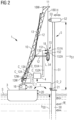
- FIG 2 shows elements of the inventive installation arrangement 1, 2, 3, 4 during the installation of an offshore wind turbine 5 in a water depth exceeding 50 m.
- a floating installation vessel 3 has been used to transport wind turbine components 51, 52, 53, 54 to an installation site and is being used to assemble the wind turbine 5.
- the crane 10 comprises a boom and jib with sufficient length to extend beyond the height of an assembled wind turbine 5 with a tower height in the region of 140 m.
- a sensor arrangement 2 has been provided, in this case the sensor arrangement 2 comprises a motion tracking assembly with one or more cameras 21 and various markers 20 attached at appropriate points on the floating installation vessel 3 within sight of the camera(s) 21.
- a camera 21 is stationary relative to the markers 20, and any movement of the markers will be recorded by the camera 21.
- a control unit 4 is provided which can continually receive image data from the camera(s) 21 and which can analyse the image data to determine the rotation RX, RY, RZ and also the vertical heave V of the floating installation vessel 3. The control unit 4 is also informed of the crane position, load weight, load height etc.
- control unit 4 then computes a correction required to counteract a motion RX, RY, RZ, V of the floating installation vessel 3, and generates appropriate control signals C_12A, C_13A, C_151A, C_152A, C_10 for any relevant actuator such as a winch motor 12A of a tagline 12, a winch motor 13A of a guidewire 13, a hydraulic actuator 151A, 152A of a lifting tool 15, a crane controller 16, a winch motor 18W of the hook cable 180, etc.
- the control unit 4 is not only capable of determining rotatory and translatory motion of the floating installation vessel 3, it can also be realised to sense a lateral displacement H of the wind turbine assembly 5. Wave action W on the monopile 50 can result in the entire wind turbine assembly oscillating back and forth, as explained above.
- the controller 4 can establish whether any such motion of the wind turbine tower 51 is significant enough to require corrective action, and can adjust the control signals C_12A, C_13A, C_151A, C_152A, C_10 accordingly.
- Corrections can be made continually, at regular intervals, intermittently, etc. in order to hoist the load L into place at the target.
- the load may be hoisted partway to the target without considering any corrective action.
- the corrective signals computed by the control unit may be applied shortly before the load is to "dock" with the target.
- the control unit 4 may be realised in a computer, a handheld device, etc.
- Fig 3 shows how a sensor arrangement 2 may be achieved.
- one or more cameras 21 are installed at a transition piece of the wind turbine 5, and are positioned to "see" markers 20 arranged at various locations on the floating installation vessel 3.
- the markers can be passive, for example brightly coloured or high-visibility paint marks or objects at the side of the floating installation vessel 3 that faces the cameras 21.
- Markers 20 may be active, for example LED lights that emit a bright light. Such a realisation can be advantageous in foggy or dim conditions. Active markers can emit in infrared light, so that they can be detected even in dark conditions. To distinguish the markers from each other and to facilitate tracking of the markers, neighbouring markers can have different colours, can emit light at different wavelengths, can emit light at different frequencies, etc.
- the sensor arrangement 2 may use sensors 22 such as accelerometers 22 to detect and rotatory motions RX, RY, RZ or a translatory motion V of the floating installation vessel 3. For example, it would be possible to track these motions using at least three accelerometers 22 arranged at suitable positions on the floating installation vessel 3.
- the controller 4 (not shown in this diagram) can collect data from cameras 21 and/or accelerometers 22, analyse the data, and determine any corrective action to be taken in order to align the load L with its target.
- Fig 4 shows a simplified lifting tool 15, in this case a lifting tool 15 that is adapted to hold a rotor blade 54 while this is being raised to a blade pitch ring of a previously installed hub on a partially assembled wind turbine.
- the lifting tool 15 has a suspension interface 151 for suspending the lifting tool 15 from a crane hook 18, which suspension interface 151 comprises a number of vertically extendable actuators 151A, in this case a vertical arrangement of hydraulic cylinders.
- the lifting tool 15 also has a gripping assembly 152 for holding the rotor blade 54, with a number of laterally extendable actuators 152A, in this case a lateral arrangement of hydraulic cylinders.
- the controller 4 can issue control signals C_151A, C_152A to control the extension and retraction of the hydraulic cylinders 151A, 152A to at least partially counteract a sensed heave motion V of the floating installation vessel 3 (the heave motion V can also be partially counteracted by controlling a motor winch of the hook cable as explained above to adjust the length of cable 180 from which the hook 18 is suspended and/or by controlling the crane's boom and jib) .
- the drawing also shows a number of sensors 20 arranged to report a change in orientation of the rotor blade 54.
- uplift U because of wind can cause the tip end of the blade 54 to push upward, thereby tilting the entire blade 54.
- the sensors 20 - for example accelerometers - can report any change in position to the controller 4, which detects the extent of uplift, and generates control signals C_151, C_152 to react accordingly in order to keep the rotor blade 54 steady.
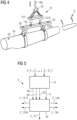
- Fig. 5 shows a simplified block diagram of the controller 4.
- the controller 4 is setup to receive data D_2 from the sensors of the sensor arrangement 2, for example image data from one or more cameras, and/or data from one or more accelerometers, etc.
- an analysis unit 41 determines any rotatory motion RX, RY, RZ of the floating installation vessel 3 as well as any heave motion V.
- the analysis unit 41 can determine that the floating installation vessel 3 is experiencing heave motion with an amplitude of ⁇ 0.5 m at a frequency of 0.2 Hz, roll motion RX of ⁇ 8° at a frequency of 0.1 Hz, and pitch motion RY of ⁇ 4° at a frequency of 0.3 Hz, and insignificant yaw motion RZ.
- a corrective signal computation module 42 computes a corrective control signal C_12A for a tagline winch 12A, a corrective control signal C_13A for a guidewire winch 13A, and a corrective control signal C_10 for a crane motor to adjust the angle of the crane boom.
Landscapes
- Engineering & Computer Science (AREA)
- Mechanical Engineering (AREA)
- General Engineering & Computer Science (AREA)
- Life Sciences & Earth Sciences (AREA)
- Sustainable Energy (AREA)
- Combustion & Propulsion (AREA)
- Chemical & Material Sciences (AREA)
- Sustainable Development (AREA)
- Automation & Control Theory (AREA)
- General Life Sciences & Earth Sciences (AREA)
- Mining & Mineral Resources (AREA)
- Paleontology (AREA)
- Civil Engineering (AREA)
- Structural Engineering (AREA)
- Wind Motors (AREA)
Claims (15)
- Dispositif d'installation hauturière d'éolienne (1, 2, 3, 4), comprenant- un ensemble de levage (1) réalisé pour hisser une charge suspendue (L) entre un vaisseau d'installation flottant (3) et un ensemble éolienne (5), lequel ensemble de levage (1) comprenant une grue (10) supportée par le vaisseau d'installation flottant (3) ;- un dispositif capteur (2) réalisé pour détecter au moins un mouvement (RX, RY, RZ ; V) du vaisseau d'installation flottant (3), et le dispositif capteur (2) comprenant de nombreux marqueurs (20) montés au niveau du vaisseau d'installation flottant (3) et de nombreuses caméras (21) montées à la base de l'ensemble éolienne (5) et agencées pour détecter les marqueurs (20) ; et- un dispositif de commande (4) réalisé pour commander des éléments (12A, 13A, 151A, 152A) de l'ensemble de levage (1) sur la base du mouvement (RX, RY, RZ ; V) détecté du vaisseau d'installation pour ajuster la position de la charge suspendue (L) par rapport à l'ensemble éolienne (5).
- Dispositif d'installation selon la revendication 1, le dispositif capteur (2) étant réalisé pour détecter un mouvement de rotation (RX, RY, RZ) du vaisseau d'installation flottant (3) et/ou un mouvement de tangage (V) du vaisseau d'installation flottant (3).
- Dispositif d'installation selon la revendication 1 ou la revendication 2, le dispositif capteur (2) étant réalisé pour détecter un déplacement latéral (H) de l'ensemble éolienne (5).
- Dispositif d'installation selon l'une quelconque des revendications précédentes, l'ensemble de levage (1) comprenant un outil de levage (15) avec une interface de suspension (151) pour suspendre l'outil de levage (15) depuis un crochet de grue (18), laquelle interface de suspension (151) comprenant de nombreux actionneurs pouvant être étendus verticalement (151A), et le dispositif de commande (4) étant réalisé pour commander un actionneur pouvant être étendu verticalement (151A) au moins sur la base d'un mouvement de tangage (V) détecté du vaisseau d'installation flottant (3).
- Dispositif d'installation selon l'une quelconque des revendications précédentes, l'ensemble de levage (1) comprenant un outil de levage (15) avec un ensemble de préhension (152) pour saisir la charge (L), et un dispositif câble stabilisateur (12, 13, 130) pour stabiliser la charge (L) par rapport à la grue (10), et le dispositif de commande (4) étant réalisé pour commander au moins un moteur de treuil (12A, 13A) du dispositif câble stabilisateur (12, 13, 130) sur la base d'un mouvement de rotation (RX, RY, RZ) détecté du vaisseau d'installation flottant (3).
- Dispositif d'installation selon la revendication 5, le dispositif capteur (2) comprenant de nombreux capteurs (20) agencés pour détecter un déplacement de la charge suspendue (L), et l'ensemble de préhension (152) comprenant de nombreux actionneurs pouvant être étendus latéralement (152A), et le dispositif de commande (4) étant réalisé pour commander un actionneur pouvant être étendu latéralement (152A) sur la base du déplacement détecté de la charge (L).
- Dispositif d'installation selon la revendication 6, un actionneur (151A, 152A) de l'outil de levage (15) comprenant un cylindre hydraulique (151A, 152A).
- Dispositif d'installation selon l'une quelconque des revendications précédentes, le dispositif de commande (4) étant réalisé pour calculer un déplacement approprié d'un actionneur (12A, 13A, 151A, 152A, 16) de l'ensemble de levage (1) pour compenser un mouvement détecté (RX, RY, RZ, V).
- Dispositif d'installation selon la revendication 8, le dispositif de commande (4) étant réalisé pour générer un signal de commande (C_12A, C_13A, C_151A, C_152A, C_10) pour l'actionneur (151A, 152A, 12A, 13A, 16) sur la base du mouvement détecté (RX, RY, RZ, V).
- Dispositif d'installation selon l'une quelconque des revendications précédentes, le dispositif capteur (2) comprenant de nombreux accéléromètres (22) agencés sur le vaisseau d'installation flottant (3).
- Dispositif d'installation selon l'une quelconque des revendications précédentes, un marqueur (20) comprenant une LED qui émet de la lumière qui peut être détectée par une caméra (21).
- Dispositif d'installation selon l'une quelconque des revendications précédentes, le dispositif capteur (2) comprenant de nombreux accéléromètres (22) disposés sur la charge suspendue (L) et/ou sur un outil de levage (15) maintenant la charge suspendue (L).
- Dispositif d'installation selon l'une quelconque des revendications précédentes, le dispositif d'installation (1) étant adapté pour l'installation d'une éolienne hauturière (5) avec une hauteur de tour d'au moins 100 m, préférablement d'au moins 120 m et/ou le dispositif d'installation (1) étant adapté pour l'installation d'une éolienne hauturière (5) à une profondeur d'eau d'au moins 40 m, plus préférablement d'au moins 50 m.
- Procédé de hissage d'une charge (L) entre un vaisseau d'installation flottant (3) et un ensemble éolienne hauturière (5), lequel procédé comprend les étapes consistant à- fournir un ensemble de levage (1), comprenant une grue (10) supportée par un vaisseau d'installation flottant (3), pour hisser la charge (L) ;- détecter un mouvement (RX, RY, RZ ; V) du vaisseau d'installation flottant (3) durant la manœuvre de levage en utilisant un dispositif capteur comprenant de nombreux marqueurs (20) montés au vaisseau d'installation flottant (3) et de nombreuses caméras (21) montées à la base de l'ensemble éolienne (5) et agencées pour détecter les marqueurs (20) ; et- à commander des éléments (12A, 13A, 151A, 152A) de l'ensemble de levage (1) au moins sur la base du mouvement (RX, RY, RZ ; V) détecté du vaisseau d'installation pour ajuster la position de la charge suspendue (L) par rapport à l'ensemble éolienne (5).
- Progiciel informatique comprenant un programme informatique qui peut être directement chargé dans une mémoire d'un dispositif de commande (4) d'un dispositif d'installation (1) selon l'une quelconque des revendications 1 à 13, et qui comprend des éléments de programme pour exécuter des étapes du procédé selon la revendication 14 lorsque le programme informatique est exécuté par le dispositif de commande (4) du dispositif d'installation (1) .
Applications Claiming Priority (2)
| Application Number | Priority Date | Filing Date | Title |
|---|---|---|---|
| DE102017209876 | 2017-06-12 | ||
| PCT/EP2018/063939 WO2018228809A1 (fr) | 2017-06-12 | 2018-05-28 | Agencement d'installation d'éolienne offshore |
Publications (2)
| Publication Number | Publication Date |
|---|---|
| EP3601793A1 EP3601793A1 (fr) | 2020-02-05 |
| EP3601793B1 true EP3601793B1 (fr) | 2024-05-29 |
Family
ID=62567615
Family Applications (1)
| Application Number | Title | Priority Date | Filing Date |
|---|---|---|---|
| EP18730267.4A Active EP3601793B1 (fr) | 2017-06-12 | 2018-05-28 | Agencement d'installation d'éolienne offshore |
Country Status (4)
| Country | Link |
|---|---|
| US (1) | US11198597B2 (fr) |
| EP (1) | EP3601793B1 (fr) |
| CN (1) | CN110709602B (fr) |
| WO (1) | WO2018228809A1 (fr) |
Families Citing this family (27)
| Publication number | Priority date | Publication date | Assignee | Title |
|---|---|---|---|---|
| WO2018160681A1 (fr) | 2017-02-28 | 2018-09-07 | J. Ray Mcdermott, S.A. | Levage navire-navire en mer avec assistance de suivi de cible |
| IT201700068019A1 (it) * | 2017-06-19 | 2018-12-19 | Saipem Spa | Telaio stabilizzatore, sistema e metodo per l'installazione di un generatore eolico su una struttura di sostegno offshore |
| PL3695113T3 (pl) * | 2017-10-12 | 2022-08-29 | Heerema Marine Contractors Nederland Se | Układ do umieszczania zespołu turbiny wiatrowej na konstrukcji wsporczej |
| US11780711B2 (en) * | 2018-12-28 | 2023-10-10 | Vestas Wind Systems A/S | Automated tagline control system and method of handling a wind turbine component using the automated tagline control system |
| EP3902763B1 (fr) | 2018-12-28 | 2025-03-12 | Vestas Wind Systems A/S | Ensemble de levage et procédé de manipulation d'un élément |
| NL2022366B1 (en) * | 2019-01-10 | 2020-08-13 | Boskalis Bv Baggermaatschappij | Supervisory control arrangement for a vessel |
| WO2020163288A2 (fr) * | 2019-02-05 | 2020-08-13 | J. Ray Mcdermott, S.A. | Système et procédés pour déterminer une position relative et un mouvement relatif d'objets |
| EP3792486B1 (fr) * | 2019-09-16 | 2026-02-18 | Siemens Gamesa Renewable Energy A/S | Procédé de montage d'une éolienne en mer |
| EP4121654A1 (fr) * | 2020-03-20 | 2023-01-25 | Vestas Wind Systems A/S | Procédé d'installation de pièces d'un générateur éolien en mer |
| BE1028262B1 (nl) | 2020-05-04 | 2021-12-07 | Deme Offshore Be Nv | Hefsysteem en werkwijze voor het opnemen van een langwerpig object |
| CN112027909A (zh) * | 2020-08-25 | 2020-12-04 | 广东工业大学 | 一种海上巨型叶片防转动和摆动的吊装控制方法及其装置 |
| CN111997842B (zh) * | 2020-09-10 | 2021-07-06 | 明阳智慧能源集团股份公司 | 一种漂浮式双风轮风力发电机组的塔架和主机的安装方法 |
| NL2026695B1 (en) * | 2020-10-16 | 2022-06-14 | Itrec Bv | Pile holding system and method |
| CN112523964B (zh) * | 2020-12-01 | 2022-04-01 | 中交第三航务工程局有限公司宁波分公司 | 一种利用浮式起重船安装风电机组的方法 |
| NL2028204B1 (en) * | 2021-05-12 | 2022-11-29 | Itrec Bv | Vessel, device and method for the manipulation of wind turbine blades |
| NO347780B1 (en) * | 2021-12-03 | 2024-03-25 | Kongsberg Maritime As | Pull-in of dynamic cables for floating wind turbines |
| CN114212704A (zh) * | 2021-12-16 | 2022-03-22 | 大连海事大学 | 用于船用起重机减摇防摆的辅助臂 |
| DK181176B1 (en) * | 2022-01-25 | 2023-03-27 | Enabl As | Wind turbine installation system and method for installation a wind turbine |
| EP4253220A1 (fr) * | 2022-03-28 | 2023-10-04 | Technip Energies France | Plate-forme d'intervention flottante en mer dotée d'une tour de levage avec un dispositif de compensation de position, ensemble associé et procédé |
| NL2032063B1 (en) * | 2022-06-02 | 2023-12-14 | Delta Laboratories Holding B V | Load alignment control system and method therefor |
| NL2032968B1 (en) * | 2022-09-06 | 2024-03-21 | Itrec Bv | System comprising a crane and method of hoisting |
| WO2024052129A1 (fr) * | 2022-09-06 | 2024-03-14 | Itrec B.V. | Système de grue pour l'installation d'une pale de rotor d'éolienne |
| EP4368558A1 (fr) * | 2022-11-10 | 2024-05-15 | XCMG European Research Center GmbH | Procédé de commande de la position d'un élément de charge et/ou d'une charge d'une grue maintenue par un élément de charge |
| DK181779B1 (en) * | 2023-02-02 | 2024-12-13 | Liftra Ip Aps | A method for controlling the position of a blade lifting yoke and a blade lifting yoke for a rotor blade for a wind turbine |
| CN116199119A (zh) * | 2023-02-06 | 2023-06-02 | 江苏凯恩特机械设备制造有限公司 | 一种可精确调整吊件姿态的多点平衡吊装系统 |
| CN116495639B (zh) * | 2023-04-19 | 2025-11-18 | 武汉科技大学 | 船载起重机起吊端物体位姿平衡的补偿装置及补偿方法 |
| EP4559856A1 (fr) * | 2023-11-23 | 2025-05-28 | Siemens Gamesa Renewable Energy A/S | Dispositif de retenue et procédé de placement d'un objet sur une plateforme en mer |
Family Cites Families (30)
| Publication number | Priority date | Publication date | Assignee | Title |
|---|---|---|---|---|
| FR2344490A1 (fr) * | 1976-03-18 | 1977-10-14 | Elf Aquitaine | Dispositif de compensation des variations de distance entre un objet flottant sur l'eau et le fond de celle-ci |
| FR2401868A1 (fr) * | 1977-08-31 | 1979-03-30 | Bretagne Atel Chantiers | Procede et dispositif d'enlevement et de depose de charges entre deux supports animes de mouvements relatifs verticaux repetes |
| US4713798A (en) * | 1983-12-09 | 1987-12-15 | Leslie Kay | Method of and apparatus for providing object data by machine vision |
| US4883184A (en) * | 1986-05-23 | 1989-11-28 | Albus James S | Cable arrangement and lifting platform for stabilized load lifting |
| US5089972A (en) * | 1990-12-13 | 1992-02-18 | Nachman Precision Systems, Inc. | Moored ship motion determination system |
| GB2267360B (en) | 1992-05-22 | 1995-12-06 | Octec Ltd | Method and system for interacting with floating objects |
| US6232735B1 (en) * | 1998-11-24 | 2001-05-15 | Thames Co., Ltd. | Robot remote control system and robot image remote control processing system |
| US6505574B1 (en) * | 2001-09-05 | 2003-01-14 | The United States Of America As Represented By The Secretary Of The Navy | Vertical motion compensation for a crane's load |
| US6826452B1 (en) * | 2002-03-29 | 2004-11-30 | The Penn State Research Foundation | Cable array robot for material handling |
| US7289875B2 (en) * | 2003-11-14 | 2007-10-30 | Siemens Technology-To-Business Center Llc | Systems and methods for sway control |
| EP1925582B1 (fr) * | 2006-11-23 | 2010-06-23 | Siemens Aktiengesellschaft | Procédé et dispositif de montage de pales d'éoliennes |
| US7367464B1 (en) * | 2007-01-30 | 2008-05-06 | The United States Of America As Represented By The Secretary Of The Navy | Pendulation control system with active rider block tagline system for shipboard cranes |
| US20090232625A1 (en) * | 2007-09-14 | 2009-09-17 | Almeda Jr Benjamin M | Motion compensation system |
| DE102008024513B4 (de) * | 2008-05-21 | 2017-08-24 | Liebherr-Werk Nenzing Gmbh | Kransteuerung mit aktiver Seegangsfolge |
| CN201261694Y (zh) * | 2008-08-20 | 2009-06-24 | 大连华锐股份有限公司 | 大型全回转海上平台起重机 |
| US8195368B1 (en) * | 2008-11-07 | 2012-06-05 | The United States Of America As Represented By The Secretary Of The Navy | Coordinated control of two shipboard cranes for cargo transfer with ship motion compensation |
| EP2473400B1 (fr) * | 2009-09-04 | 2015-06-17 | Itrec B.V. | Installation d'un generateur eolique en haute-mer |
| GB2479232B (en) * | 2010-03-10 | 2017-04-19 | W3G Shipping Ltd | Offshore structures and associated apparatus and methods |
| BR112012027304B1 (pt) | 2010-04-29 | 2020-12-22 | National Oilwell Varco L.P | sistema de controle de guindaste e processo de operação de um guindaste |
| CN102616339B (zh) * | 2011-01-30 | 2014-10-29 | 华锐风电科技(江苏)有限公司 | 一种风电机组的运输安装船及风电机组的船运和安装方法 |
| DE102011102025A1 (de) * | 2011-05-19 | 2012-11-22 | Liebherr-Werk Nenzing Gmbh | Kransteuerung |
| WO2012161584A1 (fr) | 2011-05-20 | 2012-11-29 | Optilift As | Système, dispositif et procédé pour suivre position et orientation de véhicule, dispositif de chargement et chargement dans opérations de dispositif de chargement |
| DE102012004803A1 (de) * | 2012-03-09 | 2013-09-12 | Liebherr-Werk Nenzing Gmbh | Kransteuerung mit Antriebsbeschränkung |
| DK177683B1 (en) | 2012-08-30 | 2014-03-03 | Envision Energy Denmark Aps | Method of installing an offshore wind turbine and a transport vessel thereof |
| US9950910B2 (en) * | 2012-09-11 | 2018-04-24 | Eltronic A/S | Method for controlling the orientation of a load suspended from a bearing wire about said bearing wire and a winch arrangement |
| EP2953883B1 (fr) * | 2013-02-05 | 2017-04-05 | Barge Master IP B.V. | Dispositif de compensation de mouvement et procédé de transfert de charge |
| WO2015022001A1 (fr) * | 2013-08-12 | 2015-02-19 | Abb Technology Ltd | Procédé et système pour déposer automatiquement des conteneurs sur une cible de déposition à l'aide d'une grue à conteneurs |
| NL2013409B1 (en) | 2014-09-03 | 2016-09-27 | Fugro N V | Spatial positioning of offshore structures. |
| KR101657224B1 (ko) * | 2015-02-09 | 2016-09-13 | 박병룡 | 풍력타워 설치용 해상 크레인 |
| US9849944B2 (en) | 2015-10-05 | 2017-12-26 | Keppel Offshore & Marine Technology Centre Pte. Ltd. | System and method for guiding cargo transfer between two bodies |
-
2018
- 2018-05-28 EP EP18730267.4A patent/EP3601793B1/fr active Active
- 2018-05-28 WO PCT/EP2018/063939 patent/WO2018228809A1/fr not_active Ceased
- 2018-05-28 US US16/618,942 patent/US11198597B2/en active Active
- 2018-05-28 CN CN201880039213.1A patent/CN110709602B/zh active Active
Also Published As
| Publication number | Publication date |
|---|---|
| US20200141388A1 (en) | 2020-05-07 |
| CN110709602B (zh) | 2022-04-15 |
| CN110709602A (zh) | 2020-01-17 |
| US11198597B2 (en) | 2021-12-14 |
| WO2018228809A1 (fr) | 2018-12-20 |
| EP3601793A1 (fr) | 2020-02-05 |
Similar Documents
| Publication | Publication Date | Title |
|---|---|---|
| EP3601793B1 (fr) | Agencement d'installation d'éolienne offshore | |
| EP3601139B1 (fr) | Agencement de levage pour une éolienne | |
| CN104039678B (zh) | 具有船和波浪运动的全动态补偿的船和起重机及其控制方法 | |
| EP3802396B1 (fr) | Navire en mer, de préférence navire d'installation de turbine éolienne en mer, grue pour procurer un tel navire, et procédé pour utiliser une telle grue, de préférence pour relever un monopieu | |
| EP3615467B1 (fr) | Grue à compensation de mouvement destinée à être utilisée sur un navire en mer | |
| CA2775641C (fr) | Appareil et methodes de positionnement d'un objet dans un environnement sous-marin | |
| WO2010062188A1 (fr) | Système de transport marin et procédé d’utilisation de celui-ci | |
| WO2014070024A2 (fr) | Système et procédé de transport et de montage | |
| WO2023279623A1 (fr) | Structure flottante de levage de navire et procédé associé | |
| EP4422968A1 (fr) | Installation d'un monopieu adapté pour supporter une éolienne en mer | |
| AU2021281375B2 (en) | Offshore transfer system with internal relative movement compensation | |
| EP4714817A2 (fr) | Procédé de commande de transfert d'une charge suspendue entre une éolienne en mer et un navire flottant | |
| EP4559856A1 (fr) | Dispositif de retenue et procédé de placement d'un objet sur une plateforme en mer | |
| CN121224915A (zh) | 一种甲板驳船海上系泊的自适应装置 |
Legal Events
| Date | Code | Title | Description |
|---|---|---|---|
| STAA | Information on the status of an ep patent application or granted ep patent |
Free format text: STATUS: UNKNOWN |
|
| STAA | Information on the status of an ep patent application or granted ep patent |
Free format text: STATUS: THE INTERNATIONAL PUBLICATION HAS BEEN MADE |
|
| PUAI | Public reference made under article 153(3) epc to a published international application that has entered the european phase |
Free format text: ORIGINAL CODE: 0009012 |
|
| STAA | Information on the status of an ep patent application or granted ep patent |
Free format text: STATUS: REQUEST FOR EXAMINATION WAS MADE |
|
| 17P | Request for examination filed |
Effective date: 20191031 |
|
| AK | Designated contracting states |
Kind code of ref document: A1 Designated state(s): AL AT BE BG CH CY CZ DE DK EE ES FI FR GB GR HR HU IE IS IT LI LT LU LV MC MK MT NL NO PL PT RO RS SE SI SK SM TR |
|
| AX | Request for extension of the european patent |
Extension state: BA ME |
|
| DAV | Request for validation of the european patent (deleted) | ||
| DAX | Request for extension of the european patent (deleted) | ||
| STAA | Information on the status of an ep patent application or granted ep patent |
Free format text: STATUS: EXAMINATION IS IN PROGRESS |
|
| 17Q | First examination report despatched |
Effective date: 20220317 |
|
| TPAC | Observations filed by third parties |
Free format text: ORIGINAL CODE: EPIDOSNTIPA |
|
| GRAP | Despatch of communication of intention to grant a patent |
Free format text: ORIGINAL CODE: EPIDOSNIGR1 |
|
| STAA | Information on the status of an ep patent application or granted ep patent |
Free format text: STATUS: GRANT OF PATENT IS INTENDED |
|
| INTG | Intention to grant announced |
Effective date: 20240119 |
|
| RAP3 | Party data changed (applicant data changed or rights of an application transferred) |
Owner name: SIEMENS GAMESA RENEWABLE ENERGY A/S |
|
| GRAS | Grant fee paid |
Free format text: ORIGINAL CODE: EPIDOSNIGR3 |
|
| GRAA | (expected) grant |
Free format text: ORIGINAL CODE: 0009210 |
|
| STAA | Information on the status of an ep patent application or granted ep patent |
Free format text: STATUS: THE PATENT HAS BEEN GRANTED |
|
| AK | Designated contracting states |
Kind code of ref document: B1 Designated state(s): AL AT BE BG CH CY CZ DE DK EE ES FI FR GB GR HR HU IE IS IT LI LT LU LV MC MK MT NL NO PL PT RO RS SE SI SK SM TR |
|
| REG | Reference to a national code |
Ref country code: CH Ref legal event code: EP |
|
| REG | Reference to a national code |
Ref country code: IE Ref legal event code: FG4D |
|
| REG | Reference to a national code |
Ref country code: DE Ref legal event code: R096 Ref document number: 602018070038 Country of ref document: DE |
|
| REG | Reference to a national code |
Ref country code: LT Ref legal event code: MG9D |
|
| REG | Reference to a national code |
Ref country code: NL Ref legal event code: MP Effective date: 20240529 |
|
| PG25 | Lapsed in a contracting state [announced via postgrant information from national office to epo] |
Ref country code: IS Free format text: LAPSE BECAUSE OF FAILURE TO SUBMIT A TRANSLATION OF THE DESCRIPTION OR TO PAY THE FEE WITHIN THE PRESCRIBED TIME-LIMIT Effective date: 20240929 |
|
| PG25 | Lapsed in a contracting state [announced via postgrant information from national office to epo] |
Ref country code: BG Free format text: LAPSE BECAUSE OF FAILURE TO SUBMIT A TRANSLATION OF THE DESCRIPTION OR TO PAY THE FEE WITHIN THE PRESCRIBED TIME-LIMIT Effective date: 20240529 |
|
| PG25 | Lapsed in a contracting state [announced via postgrant information from national office to epo] |
Ref country code: HR Free format text: LAPSE BECAUSE OF FAILURE TO SUBMIT A TRANSLATION OF THE DESCRIPTION OR TO PAY THE FEE WITHIN THE PRESCRIBED TIME-LIMIT Effective date: 20240529 Ref country code: FI Free format text: LAPSE BECAUSE OF FAILURE TO SUBMIT A TRANSLATION OF THE DESCRIPTION OR TO PAY THE FEE WITHIN THE PRESCRIBED TIME-LIMIT Effective date: 20240529 |
|
| PG25 | Lapsed in a contracting state [announced via postgrant information from national office to epo] |
Ref country code: GR Free format text: LAPSE BECAUSE OF FAILURE TO SUBMIT A TRANSLATION OF THE DESCRIPTION OR TO PAY THE FEE WITHIN THE PRESCRIBED TIME-LIMIT Effective date: 20240830 |
|
| REG | Reference to a national code |
Ref country code: AT Ref legal event code: MK05 Ref document number: 1690853 Country of ref document: AT Kind code of ref document: T Effective date: 20240529 |
|
| PG25 | Lapsed in a contracting state [announced via postgrant information from national office to epo] |
Ref country code: ES Free format text: LAPSE BECAUSE OF FAILURE TO SUBMIT A TRANSLATION OF THE DESCRIPTION OR TO PAY THE FEE WITHIN THE PRESCRIBED TIME-LIMIT Effective date: 20240529 |
|
| PG25 | Lapsed in a contracting state [announced via postgrant information from national office to epo] |
Ref country code: AT Free format text: LAPSE BECAUSE OF FAILURE TO SUBMIT A TRANSLATION OF THE DESCRIPTION OR TO PAY THE FEE WITHIN THE PRESCRIBED TIME-LIMIT Effective date: 20240529 |
|
| PG25 | Lapsed in a contracting state [announced via postgrant information from national office to epo] |
Ref country code: PL Free format text: LAPSE BECAUSE OF FAILURE TO SUBMIT A TRANSLATION OF THE DESCRIPTION OR TO PAY THE FEE WITHIN THE PRESCRIBED TIME-LIMIT Effective date: 20240529 |
|
| PG25 | Lapsed in a contracting state [announced via postgrant information from national office to epo] |
Ref country code: LV Free format text: LAPSE BECAUSE OF FAILURE TO SUBMIT A TRANSLATION OF THE DESCRIPTION OR TO PAY THE FEE WITHIN THE PRESCRIBED TIME-LIMIT Effective date: 20240529 |
|
| PG25 | Lapsed in a contracting state [announced via postgrant information from national office to epo] |
Ref country code: PL Free format text: LAPSE BECAUSE OF FAILURE TO SUBMIT A TRANSLATION OF THE DESCRIPTION OR TO PAY THE FEE WITHIN THE PRESCRIBED TIME-LIMIT Effective date: 20240529 Ref country code: NO Free format text: LAPSE BECAUSE OF FAILURE TO SUBMIT A TRANSLATION OF THE DESCRIPTION OR TO PAY THE FEE WITHIN THE PRESCRIBED TIME-LIMIT Effective date: 20240829 Ref country code: LV Free format text: LAPSE BECAUSE OF FAILURE TO SUBMIT A TRANSLATION OF THE DESCRIPTION OR TO PAY THE FEE WITHIN THE PRESCRIBED TIME-LIMIT Effective date: 20240529 Ref country code: IS Free format text: LAPSE BECAUSE OF FAILURE TO SUBMIT A TRANSLATION OF THE DESCRIPTION OR TO PAY THE FEE WITHIN THE PRESCRIBED TIME-LIMIT Effective date: 20240929 Ref country code: HR Free format text: LAPSE BECAUSE OF FAILURE TO SUBMIT A TRANSLATION OF THE DESCRIPTION OR TO PAY THE FEE WITHIN THE PRESCRIBED TIME-LIMIT Effective date: 20240529 Ref country code: GR Free format text: LAPSE BECAUSE OF FAILURE TO SUBMIT A TRANSLATION OF THE DESCRIPTION OR TO PAY THE FEE WITHIN THE PRESCRIBED TIME-LIMIT Effective date: 20240830 Ref country code: FI Free format text: LAPSE BECAUSE OF FAILURE TO SUBMIT A TRANSLATION OF THE DESCRIPTION OR TO PAY THE FEE WITHIN THE PRESCRIBED TIME-LIMIT Effective date: 20240529 Ref country code: ES Free format text: LAPSE BECAUSE OF FAILURE TO SUBMIT A TRANSLATION OF THE DESCRIPTION OR TO PAY THE FEE WITHIN THE PRESCRIBED TIME-LIMIT Effective date: 20240529 Ref country code: BG Free format text: LAPSE BECAUSE OF FAILURE TO SUBMIT A TRANSLATION OF THE DESCRIPTION OR TO PAY THE FEE WITHIN THE PRESCRIBED TIME-LIMIT Effective date: 20240529 Ref country code: AT Free format text: LAPSE BECAUSE OF FAILURE TO SUBMIT A TRANSLATION OF THE DESCRIPTION OR TO PAY THE FEE WITHIN THE PRESCRIBED TIME-LIMIT Effective date: 20240529 Ref country code: RS Free format text: LAPSE BECAUSE OF FAILURE TO SUBMIT A TRANSLATION OF THE DESCRIPTION OR TO PAY THE FEE WITHIN THE PRESCRIBED TIME-LIMIT Effective date: 20240829 |
|
| PG25 | Lapsed in a contracting state [announced via postgrant information from national office to epo] |
Ref country code: NL Free format text: LAPSE BECAUSE OF FAILURE TO SUBMIT A TRANSLATION OF THE DESCRIPTION OR TO PAY THE FEE WITHIN THE PRESCRIBED TIME-LIMIT Effective date: 20240529 |
|
| PG25 | Lapsed in a contracting state [announced via postgrant information from national office to epo] |
Ref country code: NL Free format text: LAPSE BECAUSE OF FAILURE TO SUBMIT A TRANSLATION OF THE DESCRIPTION OR TO PAY THE FEE WITHIN THE PRESCRIBED TIME-LIMIT Effective date: 20240529 |
|
| REG | Reference to a national code |
Ref country code: NL Ref legal event code: NE Effective date: 20241128 |
|
| PG25 | Lapsed in a contracting state [announced via postgrant information from national office to epo] |
Ref country code: DK Free format text: LAPSE BECAUSE OF FAILURE TO SUBMIT A TRANSLATION OF THE DESCRIPTION OR TO PAY THE FEE WITHIN THE PRESCRIBED TIME-LIMIT Effective date: 20240529 |
|
| PG25 | Lapsed in a contracting state [announced via postgrant information from national office to epo] |
Ref country code: EE Free format text: LAPSE BECAUSE OF FAILURE TO SUBMIT A TRANSLATION OF THE DESCRIPTION OR TO PAY THE FEE WITHIN THE PRESCRIBED TIME-LIMIT Effective date: 20240529 |
|
| PG25 | Lapsed in a contracting state [announced via postgrant information from national office to epo] |
Ref country code: CZ Free format text: LAPSE BECAUSE OF FAILURE TO SUBMIT A TRANSLATION OF THE DESCRIPTION OR TO PAY THE FEE WITHIN THE PRESCRIBED TIME-LIMIT Effective date: 20240529 |
|
| PG25 | Lapsed in a contracting state [announced via postgrant information from national office to epo] |
Ref country code: SK Free format text: LAPSE BECAUSE OF FAILURE TO SUBMIT A TRANSLATION OF THE DESCRIPTION OR TO PAY THE FEE WITHIN THE PRESCRIBED TIME-LIMIT Effective date: 20240529 Ref country code: RO Free format text: LAPSE BECAUSE OF FAILURE TO SUBMIT A TRANSLATION OF THE DESCRIPTION OR TO PAY THE FEE WITHIN THE PRESCRIBED TIME-LIMIT Effective date: 20240529 |
|
| PG25 | Lapsed in a contracting state [announced via postgrant information from national office to epo] |
Ref country code: SM Free format text: LAPSE BECAUSE OF FAILURE TO SUBMIT A TRANSLATION OF THE DESCRIPTION OR TO PAY THE FEE WITHIN THE PRESCRIBED TIME-LIMIT Effective date: 20240529 |
|
| PG25 | Lapsed in a contracting state [announced via postgrant information from national office to epo] |
Ref country code: SM Free format text: LAPSE BECAUSE OF FAILURE TO SUBMIT A TRANSLATION OF THE DESCRIPTION OR TO PAY THE FEE WITHIN THE PRESCRIBED TIME-LIMIT Effective date: 20240529 Ref country code: SK Free format text: LAPSE BECAUSE OF FAILURE TO SUBMIT A TRANSLATION OF THE DESCRIPTION OR TO PAY THE FEE WITHIN THE PRESCRIBED TIME-LIMIT Effective date: 20240529 Ref country code: RO Free format text: LAPSE BECAUSE OF FAILURE TO SUBMIT A TRANSLATION OF THE DESCRIPTION OR TO PAY THE FEE WITHIN THE PRESCRIBED TIME-LIMIT Effective date: 20240529 Ref country code: EE Free format text: LAPSE BECAUSE OF FAILURE TO SUBMIT A TRANSLATION OF THE DESCRIPTION OR TO PAY THE FEE WITHIN THE PRESCRIBED TIME-LIMIT Effective date: 20240529 Ref country code: DK Free format text: LAPSE BECAUSE OF FAILURE TO SUBMIT A TRANSLATION OF THE DESCRIPTION OR TO PAY THE FEE WITHIN THE PRESCRIBED TIME-LIMIT Effective date: 20240529 Ref country code: CZ Free format text: LAPSE BECAUSE OF FAILURE TO SUBMIT A TRANSLATION OF THE DESCRIPTION OR TO PAY THE FEE WITHIN THE PRESCRIBED TIME-LIMIT Effective date: 20240529 |
|
| PG25 | Lapsed in a contracting state [announced via postgrant information from national office to epo] |
Ref country code: IT Free format text: LAPSE BECAUSE OF FAILURE TO SUBMIT A TRANSLATION OF THE DESCRIPTION OR TO PAY THE FEE WITHIN THE PRESCRIBED TIME-LIMIT Effective date: 20240529 |
|
| REG | Reference to a national code |
Ref country code: DE Ref legal event code: R097 Ref document number: 602018070038 Country of ref document: DE |
|
| PLBE | No opposition filed within time limit |
Free format text: ORIGINAL CODE: 0009261 |
|
| STAA | Information on the status of an ep patent application or granted ep patent |
Free format text: STATUS: NO OPPOSITION FILED WITHIN TIME LIMIT |
|
| PG25 | Lapsed in a contracting state [announced via postgrant information from national office to epo] |
Ref country code: SI Free format text: LAPSE BECAUSE OF FAILURE TO SUBMIT A TRANSLATION OF THE DESCRIPTION OR TO PAY THE FEE WITHIN THE PRESCRIBED TIME-LIMIT Effective date: 20240529 |
|
| 26N | No opposition filed |
Effective date: 20250303 |
|
| PGFP | Annual fee paid to national office [announced via postgrant information from national office to epo] |
Ref country code: DE Payment date: 20250528 Year of fee payment: 8 |
|
| PGFP | Annual fee paid to national office [announced via postgrant information from national office to epo] |
Ref country code: FR Payment date: 20250526 Year of fee payment: 8 |
|
| PG25 | Lapsed in a contracting state [announced via postgrant information from national office to epo] |
Ref country code: SE Free format text: LAPSE BECAUSE OF FAILURE TO SUBMIT A TRANSLATION OF THE DESCRIPTION OR TO PAY THE FEE WITHIN THE PRESCRIBED TIME-LIMIT Effective date: 20240529 |
|
| REG | Reference to a national code |
Ref country code: CH Ref legal event code: H13 Free format text: ST27 STATUS EVENT CODE: U-0-0-H10-H13 (AS PROVIDED BY THE NATIONAL OFFICE) Effective date: 20251223 |
|
| PG25 | Lapsed in a contracting state [announced via postgrant information from national office to epo] |
Ref country code: LU Free format text: LAPSE BECAUSE OF NON-PAYMENT OF DUE FEES Effective date: 20250528 |
|
| PG25 | Lapsed in a contracting state [announced via postgrant information from national office to epo] |
Ref country code: CH Free format text: LAPSE BECAUSE OF NON-PAYMENT OF DUE FEES Effective date: 20250531 |
|
| REG | Reference to a national code |
Ref country code: BE Ref legal event code: MM Effective date: 20250531 |
|
| PG25 | Lapsed in a contracting state [announced via postgrant information from national office to epo] |
Ref country code: MC Free format text: LAPSE BECAUSE OF FAILURE TO SUBMIT A TRANSLATION OF THE DESCRIPTION OR TO PAY THE FEE WITHIN THE PRESCRIBED TIME-LIMIT Effective date: 20240529 |
|
| PGFP | Annual fee paid to national office [announced via postgrant information from national office to epo] |
Ref country code: GB Payment date: 20260323 Year of fee payment: 9 |
|
| PG25 | Lapsed in a contracting state [announced via postgrant information from national office to epo] |
Ref country code: IE Free format text: LAPSE BECAUSE OF NON-PAYMENT OF DUE FEES Effective date: 20250528 |
|
| PG25 | Lapsed in a contracting state [announced via postgrant information from national office to epo] |
Ref country code: BE Free format text: LAPSE BECAUSE OF NON-PAYMENT OF DUE FEES Effective date: 20250531 |