EP3601833B1 - Frein à disque pour véhicule utilitaire - Google Patents
Frein à disque pour véhicule utilitaire Download PDFInfo
- Publication number
- EP3601833B1 EP3601833B1 EP18715514.8A EP18715514A EP3601833B1 EP 3601833 B1 EP3601833 B1 EP 3601833B1 EP 18715514 A EP18715514 A EP 18715514A EP 3601833 B1 EP3601833 B1 EP 3601833B1
- Authority
- EP
- European Patent Office
- Prior art keywords
- brake
- disc
- wear
- calliper
- carrier
- Prior art date
- Legal status (The legal status is an assumption and is not a legal conclusion. Google has not performed a legal analysis and makes no representation as to the accuracy of the status listed.)
- Active
Links
Images



Classifications
-
- F—MECHANICAL ENGINEERING; LIGHTING; HEATING; WEAPONS; BLASTING
- F16—ENGINEERING ELEMENTS AND UNITS; GENERAL MEASURES FOR PRODUCING AND MAINTAINING EFFECTIVE FUNCTIONING OF MACHINES OR INSTALLATIONS; THERMAL INSULATION IN GENERAL
- F16D—COUPLINGS FOR TRANSMITTING ROTATION; CLUTCHES; BRAKES
- F16D66/00—Arrangements for monitoring working conditions, e.g. wear, temperature
- F16D66/02—Apparatus for indicating wear
- F16D66/021—Apparatus for indicating wear using electrical detection or indication means
- F16D66/028—Apparatus for indicating wear using electrical detection or indication means with non-electrical sensors or signal transmission, e.g. magnetic, optical
-
- F—MECHANICAL ENGINEERING; LIGHTING; HEATING; WEAPONS; BLASTING
- F16—ENGINEERING ELEMENTS AND UNITS; GENERAL MEASURES FOR PRODUCING AND MAINTAINING EFFECTIVE FUNCTIONING OF MACHINES OR INSTALLATIONS; THERMAL INSULATION IN GENERAL
- F16D—COUPLINGS FOR TRANSMITTING ROTATION; CLUTCHES; BRAKES
- F16D55/00—Brakes with substantially-radial braking surfaces pressed together in axial direction, e.g. disc brakes
- F16D55/02—Brakes with substantially-radial braking surfaces pressed together in axial direction, e.g. disc brakes with axially-movable discs or pads pressed against axially-located rotating members
- F16D55/22—Brakes with substantially-radial braking surfaces pressed together in axial direction, e.g. disc brakes with axially-movable discs or pads pressed against axially-located rotating members by clamping an axially-located rotating disc between movable braking members, e.g. movable brake discs or brake pads
- F16D55/224—Brakes with substantially-radial braking surfaces pressed together in axial direction, e.g. disc brakes with axially-movable discs or pads pressed against axially-located rotating members by clamping an axially-located rotating disc between movable braking members, e.g. movable brake discs or brake pads with a common actuating member for the braking members
- F16D55/225—Brakes with substantially-radial braking surfaces pressed together in axial direction, e.g. disc brakes with axially-movable discs or pads pressed against axially-located rotating members by clamping an axially-located rotating disc between movable braking members, e.g. movable brake discs or brake pads with a common actuating member for the braking members the braking members being brake pads
- F16D55/226—Brakes with substantially-radial braking surfaces pressed together in axial direction, e.g. disc brakes with axially-movable discs or pads pressed against axially-located rotating members by clamping an axially-located rotating disc between movable braking members, e.g. movable brake discs or brake pads with a common actuating member for the braking members the braking members being brake pads in which the common actuating member is moved axially, e.g. floating caliper disc brakes
-
- F—MECHANICAL ENGINEERING; LIGHTING; HEATING; WEAPONS; BLASTING
- F16—ENGINEERING ELEMENTS AND UNITS; GENERAL MEASURES FOR PRODUCING AND MAINTAINING EFFECTIVE FUNCTIONING OF MACHINES OR INSTALLATIONS; THERMAL INSULATION IN GENERAL
- F16D—COUPLINGS FOR TRANSMITTING ROTATION; CLUTCHES; BRAKES
- F16D66/00—Arrangements for monitoring working conditions, e.g. wear, temperature
- F16D66/02—Apparatus for indicating wear
- F16D66/021—Apparatus for indicating wear using electrical detection or indication means
- F16D66/026—Apparatus for indicating wear using electrical detection or indication means indicating different degrees of lining wear
Definitions
- the invention relates to a disc brake for a commercial vehicle according to the preamble of claim 1.
- the disc brakes are usually equipped with wear detection devices, which can be used to detect wear on the brake pads and/or the brake disc. With the help of such wear detection devices, a necessary replacement of the affected components, i.e. the brake pads or the brake disc, can be carried out at the best possible time.
- a disc brake with a cast brake carrier and brake caliper is known, material projections with essentially flat surfaces aligned parallel to the brake disc surface being provided for visual wear detection on both the brake carrier and the brake caliper.
- Wear indicators are also known, which use a rotary potentiometer to determine a travel position of an adjustment device that occurs when the brake caliper is adjusted as a result of the wear of the brake pads.
- a disadvantage of the wear detection devices known from the prior art is the considerable structural effort involved in integrating such components when rotary potentiometers and the like are used, or in the latter case the visual recognizability when the vehicle wheel is mounted.
- the object of the present invention is to further develop a disc brake of the generic type in such a way that a simple, reliable and precise detection of the state of wear of the brake pads and/or the brake disc is made possible with little design and manufacturing effort.
- the disc brake according to the invention for a commercial vehicle has a brake carrier that engages over a brake disc and has a flange area for fixing the brake carrier to a vehicle axle of the commercial vehicle and a receiving area for supporting at least one brake pad.
- the disc brake also has a brake caliper held on the brake carrier so that it can be displaced axially in the direction of an axis of rotation of the brake disc.
- Brake pads can be positioned within the brake caliper on both sides of the brake disc and can be pressed against the brake disc by means of a clamping device during braking.
- the disc brake also has a device for visual wear detection of brake disc wear and/or brake pad wear.
- This device for visual wear detection has a material projection formed in the flange area of the brake carrier and a mechanically reworked flat reference surface formed on the brake caliper and aligned perpendicular to the displacement direction of the brake caliper.
- the material projection has a plurality of mechanically reworked flat surfaces aligned one behind the other in the displacement direction of the brake caliper and perpendicular to the displacement direction of the brake caliper, with the surfaces of the material projection and the reference surface of the brake caliper being positioned in such a way that they are visually recognizable at the same time from a predetermined viewing direction.
- the surfaces of the material projection and the reference surface on the brake caliper are mechanically, in particular machined, reworked in order to further improve the accuracy of the wear indicator.
- the mechanical post-processing of the surfaces used for visual wear detection also makes it possible, in particular, to also determine differential wear between an inner and outer brake lining in conjunction with a total wear sensor of the disc brake. This requires an accurate readability of the optical wear indicator, which can only be achieved with machined surfaces, since the surface of a raw casting does not allow such precise readability.
- a first surface of the material projection close to the brake disc is positioned in such a way that, in a position of the brake caliper aligned with the reference surface of the brake caliper, it indicates that the brake disc and the brake pads are new and free of wear, while a second surface of the Material projection is positioned so that it indicates a maximum permissible degree of wear in a flush with the reference surface of the brake caliper position of the brake caliper.
- the new condition and the optimum replacement condition of the brake pads and/or the brake disc can be identified in a simple manner.
- a third surface is positioned in such a way that when the brake caliper is in alignment with the reference surface of the brake caliper, it shows half the maximum permissible degree of wear, which means that the estimate of intermediate states of partially worn brake discs or brake pads that is necessary with only two surfaces according to the aforementioned embodiment variant is even better estimated can become.
- the material projection has an elevation on a surface of the flange region facing the brake caliper which extends in the direction of the brake caliper and whose flanks form the first surface and the second or third surface.
- the second surface and the third surface are particularly preferably formed in steps relative to one another, which in particular simplifies the production of the surfaces when casting the brake carrier.
- the surfaces of the material projection are preferably formed as cast surfaces formed during the casting of the brake carrier.
- the disc brake has a total wear sensor for determining a total wear value from the brake disc wear and the wear on the brake pads. This makes it possible to also determine differential wear between a brake pad on the application side and a brake pad on the reaction side.
- top, bottom, left, right, front, rear, etc. refer exclusively to the exemplary representation and position of the disc brake, brake disc, brake carrier, brake caliper, flange area, reference surface, surfaces, material projection and selected in the respective figures the like. These terms are not to be understood as limiting, i.e. these references can change due to different working positions or the mirror-symmetrical design or the like.
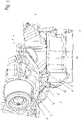
- In 1 is denoted by the reference numeral 2, a brake carrier of a disc brake 1 of a commercial vehicle.
- the brake carrier 2 has a flange area 13 which is used to fix the brake carrier 2 to a vehicle axle or another stationary body part of the utility vehicle. Screw bolts, which are passed through bores 5 in the flange area 13 of the brake carrier 2, are preferably used to fix the brake carrier 2 in place.
- the disc brake 1 corresponds, formed displaceable sliding caliper, which engages over the brake disc 22.
- two guide rails 4 are preferably provided, one of which is in 1 is shown.
- each brake lining 23, 24 consists of a lining carrier plate 25, 27 and a friction lining 26, 28 that contacts the brake disc 22 in the event of braking .
- the resulting counterforce pushes the brake caliper 3 together with the brake pad 23 on the back of the caliper, on the reaction side, in the direction of the brake disc 22 until the brake pad 23 on the reaction side is also in contact with the brake disc 22.
- Both the friction linings 26, 28 of the brake linings 23, 24 and the friction surfaces of the brake disc 22 are subject to wear in the sense of abrasion, as a result of which the position of the brake caliper 3 relative to the brake carrier 2 changes
- the disc brake 1 has a device for visual wear detection of the brake disc and/or brake pad wear.
- This device has an integrally formed in the flange 13 of the brake carrier 2 material projection 6 and an integrally formed on the caliper 3, perpendicular to Shift direction x of the brake caliper 3 aligned flat reference surface 12, as for example in 1 is shown.
- the reference surface 12 and the material projection 6 on the brake carrier 2 are provided in areas of the brake caliper 3 or the brake carrier 2 that are close together, viewed in the installed state of the brake caliper 3 on the brake carrier 2 .
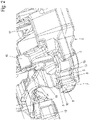
- the material projection 6 of the brake carrier 2 has, as in 1 and the inside 2 shown individual representation of the brake carrier 2, several in the direction of displacement of the brake caliper 3 one behind the other and perpendicular to the direction x of the brake caliper 3 aligned flat surfaces 8, 9, 10.
- the surfaces 8, 9 and 10 of the material projection 6 and the reference surface 12 of the brake caliper 3 are positioned on the brake carrier 2 or on the brake caliper 3 in such a way that they are simultaneously visually recognizable from a predetermined viewing direction.
- the viewing direction is preferably a direction perpendicular to the direction of displacement of the brake caliper 3 and particularly preferably also perpendicular to the direction of elevation of the material projection 6 from the brake carrier 2.
- the relative position of the surfaces 8, 9, 10 and the reference surface 12 to one another can also be seen from angular positions to the direction perpendicular to the elevation direction of the material projection 6.
- the material projection 6 is formed on the edge of the flange area 13 of the brake carrier 2 on the vehicle side.
- the material projection 6 preferably has an elevation 7 or nose extending in the direction of the brake caliper 3 on a surface 16 of the flange region 13 facing the brake caliper 3 .
- One of the brake discs close to the first surface 8 of the material projection 6 is preferably positioned in such a way that, when the brake caliper 3 is aligned with the reference surface 12 of the brake caliper 3, it indicates that the brake disc 22 and the brake pads 23, 24 are new and wear-free. This relative position of the brake carrier 2 to the brake caliper 3 is in 4 shown.
- a second surface 10 remote from the brake disc 22 is positioned so that it is in a position flush with the reference surface 12 of the brake caliper 3 Brake caliper 3 indicates a maximum permissible degree of wear. Such a relative position of the brake caliper 3 to the brake carrier 2 is in figure 5 shown.
- a third surface 9 is positioned between the first surface 8 close to the brake disc 22 and the second surface 10 remote from the brake disc 22 in such a way that, in a position of the brake caliper 3 aligned with the reference surface 12 of the brake caliper 3, it is half the maximum permissible indicates wear. This relative position of the brake caliper 3 to the brake carrier 2 is in 6 shown.
- flanks of the elevation 7 extending in the direction of the brake caliper 3 form the first surface 8 and the third surface 9, the latter serving to indicate half the maximum permissible degree of wear.
- the second surface 10 and the third surface 9 are formed in steps relative to each other, which on the one hand facilitates the production of these surfaces in a casting process in which the brake carrier 2 is manufactured and on the other hand a better visual recognition of the relative position of the brake caliper 3 to the brake carrier 2 allows.
- the surface 9 indicating half the permissible degree of wear and the surface 10 indicating the maximum permissible degree of wear are post-processed mechanically, in particular by machining, and are therefore smoother or more even than is possible with a pure cast geometry, which increases the accuracy when reading the degree of wear even further is increased.
- the stepped design also makes it easier to feel the respective degree of wear if visual recognition is restricted due to certain installation positions.
- the reference surface 12 is formed on a lower edge which, in the installed state, is very close to the flange area 13 of the brake carrier 2 and in particular to the material projection 6, as in FIG 1 is shown as an example.
- the reference surface 12 is formed obliquely below the receiving bore 20 for one of the guide rails 4 and is therefore easily visible during a visual check, since the vehicle wheel essentially covers the caliper back 18 of the brake caliper 3 .
- both the housing of the brake caliper 3 and the brake carrier 2 are preferably designed as cast parts, the material projection 6 with the surfaces 8, 9, 10 and the reference surface 12 can be molded on the brake caliper 3 in a simple manner.
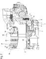
- reference surface 12 which is used for visual wear detection, and surfaces 8, 9, 10 also makes it possible, in particular, in combination with an additional cumulative wear sensor 21 installed in disc brake 1 in one embodiment, as is shown in figures 7 and 8th is shown to also determine a differential wear between the brake pad 24 on the application side and the brake pad 23 on the reaction side.
- the cumulative wear sensor 21 has a pick-up element, for example in the form of a Hall sensor, potentiometer or an inductive pick-up element, which outputs a signal in which the cumulative wear of the Brake pads 23, 24 and the brake disc 22 and the actuating stroke are superimposed.
- the cumulative wear is determined by means of a potentiometer, which detects the twisting of an adjusting element or a threaded spindle, with which a predetermined clearance between the brake disc 22 and the brake pads 23, 24 is maintained.
- the displacement of the brake caliper 3 relative to the brake carrier 2 and relative to the unworn state of the reaction-side brake pad 23 is largely due to the wear of the reaction-side brake pad 23, the displacement of the brake caliper 3 relative to the brake carrier 2 indicates a significantly greater wear value than the total wear sensor 21 .
- the wear of the friction lining 26 of the reaction-side brake lining 23 with a residual friction thickness d 2 is significantly smaller than the wear of the friction lining 28 of the application-side brake lining 24 with a residual friction thickness d 1 .
- the displacement of the brake caliper 3 relative to the brake carrier 2 shows a significantly lower wear value than the total wear sensor 21 due to the smaller displacement of the brake caliper 3 relative to the brake carrier 2.
- the degree of wear of the brake pad 24 on the application side can also be determined due to the exact reading possibility due to the mechanically reworked flat reference surface 12 on the brake caliper 3 and the mechanically reworked surfaces 8, 9 and 10 on the brake carrier 2.
- a comparison of the degree of wear with another disk brake on another side of the vehicle or axle is also conceivable, so that uneven wear between the brakes can be identified.
Landscapes
- Engineering & Computer Science (AREA)
- General Engineering & Computer Science (AREA)
- Mechanical Engineering (AREA)
- Braking Arrangements (AREA)
Claims (7)
- Frein (1) à disque d'un véhicule utilitaire, comportant- un flasque (2) de frein chevauchant un disque (22) de frein et ayant une partie (13) de bride pour la fixation du flasque (2) de frein à un essieu du véhicule utilitaire et une partie (14) de réception pour l'appui d'au moins une garniture (23, 24) de frein,- un étrier (3) de frein maintenu sur le flasque (2) de frein déplaçable axialement en direction (x) d'un axe de rotation du disque (22) de frein,dans lequel- des deux côtés du disque (22) de frein peuvent être mis en position à l'intérieur de l'étrier (3) de frein des garnitures (23, 24) de frein, qui, lors d'un freinage, peuvent être, au moyen d'un dispositif de serrage, pressées sur le disque (22) de frein,- un dispositif de détection visuelle de l'usure d'un disque de frein et/ou de l'usure d'une garniture de frein,dans lequel- le dispositif de détection visuelle de l'usure a une saillie (6) de matériau venue de moulage avec la partie (13) de bride du flasque (2) de frein et une surface (12) de référence plane réusinée mécaniquement, venue de moulage avec l'étrier (3) de frein et orientée perpendiculairement à la direction (x) de déplacement de l'étrier (3) de frein,- caractérisé en ce que la saillie (6) de matériau a plusieurs surfaces (8, 9, 10) planes finies mécaniquement, dirigées les unes derrière les autres dans la direction de déplacement de l'étrier (3) de frein et orientées perpendiculairement à la direction (x) de déplacement de l'étrier (3) de frein,- dans lequel les surfaces (8, 9, 10) de la saillie (6) de matériau et la surface (12) de référence de l'étrier (3) de frein sont placées de manière à pouvoir être détectées visuellement en même temps, à partir d'une direction de vision définie à l'avance.
- Frein à disque suivant la revendication 1, caractérisé en ce qu'une première surface (8), proche du disque (22) de frein, de la saillie (6) de matériau est placée de manière à ce que celle-ci indique, dans une position en alignement avec la surface (12) de référence de l'étrier (3) de frein, l'état nouveau sans usure du disque (22) de frein et des garnitures (23, 24) de frein, et une deuxième surface (10), loin du disque (22) de frein est placée de manière à ce que celle-ci indique dans une position, en alignement avec la surface (12) de référence de l'étrier (3) de frein, de l'étrier (3) de frein, une mesure d'usure admissible au maximum d'une garniture (23) de frein du côté de la réaction.
- Frein à disque suivant la revendication 2, caractérisé en ce qu'entre la première surface (8), proche du disque (22) de frein, et la deuxième surface (10), loin du disque (22) de frein, une troisième surface (9) est placée de manière à ce que celle-ci indique, dans une position de l'étrier (3) de frein, en alignement avec la surface (12) de référence de l'étrier (3) de frein, la demi-mesure d'usure admissible au maximum de la garniture (23) de frein du côté de la réaction.
- Frein à disque suivant l'une des revendications précédentes, caractérisé en ce que la saillie (6) de matériau a, sur une surface (16), tournée vers l'étrier (3) de frein, de la partie (13) de bride, une surélévation (7), qui s'étend dans la direction de l'étrier (3) de frein et dont les flancs forment la première surface (8) et la deuxième ou la troisième surface (9, 10).
- Frein à disque suivant la revendication 3 ou 4, caractérisé en ce que la deuxième surface (10) et la troisième surface (9) viennent de moulage en formant un palier l'une par rapport à l'autre.
- Frein à disque suivant l'une des revendications précédentes, caractérisé en ce que le frein à disque a un capteur (21) d'usure somme de détermination d'une valeur d'usure totale, à partir de l'usure du disque de frein, ainsi que de l'usure des garnitures (23, 24) de frein.
- Frein à disque suivant la revendication 6, caractérisé en ce que le capteur (21) d'usure somme a un capteur de Hall, un potentiomètre ou un élément inductif de capteur.
Applications Claiming Priority (2)
| Application Number | Priority Date | Filing Date | Title |
|---|---|---|---|
| DE102017106254.8A DE102017106254A1 (de) | 2017-03-23 | 2017-03-23 | Scheibenbremse für ein Nutzfahrzeug |
| PCT/EP2018/056899 WO2018172289A1 (fr) | 2017-03-23 | 2018-03-19 | Frein à disque pour véhicule utilitaire |
Publications (2)
| Publication Number | Publication Date |
|---|---|
| EP3601833A1 EP3601833A1 (fr) | 2020-02-05 |
| EP3601833B1 true EP3601833B1 (fr) | 2022-09-07 |
Family
ID=61899177
Family Applications (1)
| Application Number | Title | Priority Date | Filing Date |
|---|---|---|---|
| EP18715514.8A Active EP3601833B1 (fr) | 2017-03-23 | 2018-03-19 | Frein à disque pour véhicule utilitaire |
Country Status (4)
| Country | Link |
|---|---|
| EP (1) | EP3601833B1 (fr) |
| CN (1) | CN110446877B (fr) |
| DE (1) | DE102017106254A1 (fr) |
| WO (1) | WO2018172289A1 (fr) |
Citations (1)
| Publication number | Priority date | Publication date | Assignee | Title |
|---|---|---|---|---|
| EP3121477A1 (fr) * | 2015-07-21 | 2017-01-25 | Meritor Heavy Vehicle Braking Systems (UK) Limited | Ensemble de disque de frein |
Family Cites Families (12)
| Publication number | Priority date | Publication date | Assignee | Title |
|---|---|---|---|---|
| DE3612166C2 (de) | 1986-04-11 | 1995-05-11 | Teves Gmbh Alfred | Belagverschleißanzeige für Teilbelag-Scheibenbremsen, insbesondere für Kraftfahrzeuge |
| SE504466C2 (sv) * | 1995-06-08 | 1997-02-17 | Haldex Ab | Slitageindikeringsanordning för bromsbelägg |
| CN1111657C (zh) * | 1997-11-17 | 2003-06-18 | 住友电装株式会社 | 用于制动垫的磨损检测探头 |
| WO2002006691A2 (fr) * | 2000-07-13 | 2002-01-24 | Dae Sung Groundwater Ltd. | Frein pourvu d'un indicateur d'usure de garnitures |
| US7175006B2 (en) * | 2004-05-18 | 2007-02-13 | Bendix Spicer Foundation Brake Llc | Apparatus and method for sensing disc brake actuator position |
| GB0608956D0 (en) * | 2006-05-05 | 2006-06-14 | Meritor Heavy Vehicle Braking | Disc brake wear aduster |
| DE102006029042A1 (de) * | 2006-06-24 | 2008-01-03 | Bpw Bergische Achsen Kg | Scheibenbremse |
| EP2634446B1 (fr) * | 2012-02-28 | 2020-04-08 | Meritor Heavy Vehicle Braking Systems (UK) Limited | Moulage ou composant forgé avec indication de la résistance à la fatigue |
| CN203362923U (zh) * | 2013-06-24 | 2013-12-25 | 贵州永兴风能制动器有限责任公司 | 具有刹车片磨损控制器的风力发电机刹车装置 |
| US9618067B2 (en) * | 2014-12-09 | 2017-04-11 | Arvinmeritor Technology, Llc | Brake assembly and method of control |
| DE102015104916B4 (de) | 2015-03-31 | 2019-05-09 | Knorr-Bremse Systeme für Nutzfahrzeuge GmbH | Scheibenbremse für ein Nutzfahrzeug |
| DE102015107128A1 (de) * | 2015-05-07 | 2016-11-10 | Knorr-Bremse Systeme für Nutzfahrzeuge GmbH | Scheibenbremse eines Nutzfahrzeugs |
-
2017
- 2017-03-23 DE DE102017106254.8A patent/DE102017106254A1/de not_active Ceased
-
2018
- 2018-03-19 EP EP18715514.8A patent/EP3601833B1/fr active Active
- 2018-03-19 WO PCT/EP2018/056899 patent/WO2018172289A1/fr not_active Ceased
- 2018-03-19 CN CN201880020426.XA patent/CN110446877B/zh active Active
Patent Citations (1)
| Publication number | Priority date | Publication date | Assignee | Title |
|---|---|---|---|---|
| EP3121477A1 (fr) * | 2015-07-21 | 2017-01-25 | Meritor Heavy Vehicle Braking Systems (UK) Limited | Ensemble de disque de frein |
Also Published As
| Publication number | Publication date |
|---|---|
| WO2018172289A1 (fr) | 2018-09-27 |
| CN110446877B (zh) | 2021-05-25 |
| EP3601833A1 (fr) | 2020-02-05 |
| DE102017106254A1 (de) | 2018-09-27 |
| CN110446877A (zh) | 2019-11-12 |
Similar Documents
| Publication | Publication Date | Title |
|---|---|---|
| EP2812595B1 (fr) | Système de retenue de garniture d'un frein à disque d'un véhicule à moteur | |
| EP3135948B1 (fr) | Dispositif de fixation d'un capteur d'usure sur un levier de frein d'un frein de vehicule automobile | |
| EP2304266A1 (fr) | Frein à disque, en particulier pour véhicule utilitaire | |
| DE19609452A1 (de) | Scheibenbremse | |
| DE10312478A1 (de) | Scheibenbremse | |
| EP2867557B1 (fr) | Frein à disque de véhicule à moteur | |
| DE19738317B4 (de) | Vorrichtung zur kontinuierlichen Bestimmung des Verschleißzustandes von Reibbelägen | |
| EP0567155B1 (fr) | Dispositif de surveillance d'usure pour un frein à disque à étrier glissant | |
| EP3601833B1 (fr) | Frein à disque pour véhicule utilitaire | |
| WO2016034377A1 (fr) | Frein à disque d'un véhicule automobile, étrier de frein, garniture de frein et agencement d'au moins une garniture de frein dans une ouverture de poche de garniture d'un étrier de frein | |
| EP3596354B1 (fr) | Support de frein et frein à disque | |
| DE102008003528C5 (de) | Scheibenbremse eines Nutzfahrzeuges sowie Bremsbelag für eine Scheibenbremse | |
| WO2016156120A1 (fr) | Frein à disque pour véhicule utilitaire | |
| DE102008029044A1 (de) | Scheibenbremse | |
| DE102021103068B4 (de) | Bremsbelagsystem und Sensoreinheit | |
| DE102014111229A1 (de) | Scheibenbremse für ein Nutzfahrzeug | |
| DE102013114898B4 (de) | Scheibenbremse für ein Nutzfahrzeug | |
| EP2831455B1 (fr) | Frein à disque et garniture de frein | |
| EP3097320B1 (fr) | Frein à disque pour véhicule utilitaire | |
| DE10019654A1 (de) | Scheibenbremse | |
| DE102014106534B4 (de) | Scheibenbremse für ein Nutzfahrzeug | |
| WO2025196162A1 (fr) | Procédé de détermination de l'usure de plaquettes de frein d'un frein à disque, et frein à disque comportant un dispositif de mesure pour la mise en œuvre du procédé | |
| WO2022148798A1 (fr) | Système de garniture de frein et unité de détection | |
| EP4560163A1 (fr) | Garniture de frein pour un frein à tambour de véhicule | |
| DE102014111228A1 (de) | Scheibenbremse für ein Nutzfahrzeug |
Legal Events
| Date | Code | Title | Description |
|---|---|---|---|
| STAA | Information on the status of an ep patent application or granted ep patent |
Free format text: STATUS: UNKNOWN |
|
| STAA | Information on the status of an ep patent application or granted ep patent |
Free format text: STATUS: THE INTERNATIONAL PUBLICATION HAS BEEN MADE |
|
| PUAI | Public reference made under article 153(3) epc to a published international application that has entered the european phase |
Free format text: ORIGINAL CODE: 0009012 |
|
| STAA | Information on the status of an ep patent application or granted ep patent |
Free format text: STATUS: REQUEST FOR EXAMINATION WAS MADE |
|
| 17P | Request for examination filed |
Effective date: 20191023 |
|
| AK | Designated contracting states |
Kind code of ref document: A1 Designated state(s): AL AT BE BG CH CY CZ DE DK EE ES FI FR GB GR HR HU IE IS IT LI LT LU LV MC MK MT NL NO PL PT RO RS SE SI SK SM TR |
|
| AX | Request for extension of the european patent |
Extension state: BA ME |
|
| DAV | Request for validation of the european patent (deleted) | ||
| DAX | Request for extension of the european patent (deleted) | ||
| STAA | Information on the status of an ep patent application or granted ep patent |
Free format text: STATUS: EXAMINATION IS IN PROGRESS |
|
| 17Q | First examination report despatched |
Effective date: 20201014 |
|
| GRAP | Despatch of communication of intention to grant a patent |
Free format text: ORIGINAL CODE: EPIDOSNIGR1 |
|
| STAA | Information on the status of an ep patent application or granted ep patent |
Free format text: STATUS: GRANT OF PATENT IS INTENDED |
|
| INTG | Intention to grant announced |
Effective date: 20220408 |
|
| GRAS | Grant fee paid |
Free format text: ORIGINAL CODE: EPIDOSNIGR3 |
|
| GRAA | (expected) grant |
Free format text: ORIGINAL CODE: 0009210 |
|
| STAA | Information on the status of an ep patent application or granted ep patent |
Free format text: STATUS: THE PATENT HAS BEEN GRANTED |
|
| AK | Designated contracting states |
Kind code of ref document: B1 Designated state(s): AL AT BE BG CH CY CZ DE DK EE ES FI FR GB GR HR HU IE IS IT LI LT LU LV MC MK MT NL NO PL PT RO RS SE SI SK SM TR |
|
| REG | Reference to a national code |
Ref country code: GB Ref legal event code: FG4D Free format text: NOT ENGLISH |
|
| REG | Reference to a national code |
Ref country code: CH Ref legal event code: EP Ref country code: AT Ref legal event code: REF Ref document number: 1517275 Country of ref document: AT Kind code of ref document: T Effective date: 20220915 |
|
| REG | Reference to a national code |
Ref country code: DE Ref legal event code: R096 Ref document number: 502018010579 Country of ref document: DE |
|
| REG | Reference to a national code |
Ref country code: IE Ref legal event code: FG4D Free format text: LANGUAGE OF EP DOCUMENT: GERMAN |
|
| REG | Reference to a national code |
Ref country code: LT Ref legal event code: MG9D |
|
| REG | Reference to a national code |
Ref country code: NL Ref legal event code: MP Effective date: 20220907 |
|
| PG25 | Lapsed in a contracting state [announced via postgrant information from national office to epo] |
Ref country code: SE Free format text: LAPSE BECAUSE OF FAILURE TO SUBMIT A TRANSLATION OF THE DESCRIPTION OR TO PAY THE FEE WITHIN THE PRESCRIBED TIME-LIMIT Effective date: 20220907 Ref country code: RS Free format text: LAPSE BECAUSE OF FAILURE TO SUBMIT A TRANSLATION OF THE DESCRIPTION OR TO PAY THE FEE WITHIN THE PRESCRIBED TIME-LIMIT Effective date: 20220907 Ref country code: NO Free format text: LAPSE BECAUSE OF FAILURE TO SUBMIT A TRANSLATION OF THE DESCRIPTION OR TO PAY THE FEE WITHIN THE PRESCRIBED TIME-LIMIT Effective date: 20221207 Ref country code: LV Free format text: LAPSE BECAUSE OF FAILURE TO SUBMIT A TRANSLATION OF THE DESCRIPTION OR TO PAY THE FEE WITHIN THE PRESCRIBED TIME-LIMIT Effective date: 20220907 Ref country code: LT Free format text: LAPSE BECAUSE OF FAILURE TO SUBMIT A TRANSLATION OF THE DESCRIPTION OR TO PAY THE FEE WITHIN THE PRESCRIBED TIME-LIMIT Effective date: 20220907 Ref country code: FI Free format text: LAPSE BECAUSE OF FAILURE TO SUBMIT A TRANSLATION OF THE DESCRIPTION OR TO PAY THE FEE WITHIN THE PRESCRIBED TIME-LIMIT Effective date: 20220907 |
|
| PG25 | Lapsed in a contracting state [announced via postgrant information from national office to epo] |
Ref country code: HR Free format text: LAPSE BECAUSE OF FAILURE TO SUBMIT A TRANSLATION OF THE DESCRIPTION OR TO PAY THE FEE WITHIN THE PRESCRIBED TIME-LIMIT Effective date: 20220907 Ref country code: GR Free format text: LAPSE BECAUSE OF FAILURE TO SUBMIT A TRANSLATION OF THE DESCRIPTION OR TO PAY THE FEE WITHIN THE PRESCRIBED TIME-LIMIT Effective date: 20221208 |
|
| PG25 | Lapsed in a contracting state [announced via postgrant information from national office to epo] |
Ref country code: SM Free format text: LAPSE BECAUSE OF FAILURE TO SUBMIT A TRANSLATION OF THE DESCRIPTION OR TO PAY THE FEE WITHIN THE PRESCRIBED TIME-LIMIT Effective date: 20220907 Ref country code: RO Free format text: LAPSE BECAUSE OF FAILURE TO SUBMIT A TRANSLATION OF THE DESCRIPTION OR TO PAY THE FEE WITHIN THE PRESCRIBED TIME-LIMIT Effective date: 20220907 Ref country code: PT Free format text: LAPSE BECAUSE OF FAILURE TO SUBMIT A TRANSLATION OF THE DESCRIPTION OR TO PAY THE FEE WITHIN THE PRESCRIBED TIME-LIMIT Effective date: 20230109 Ref country code: ES Free format text: LAPSE BECAUSE OF FAILURE TO SUBMIT A TRANSLATION OF THE DESCRIPTION OR TO PAY THE FEE WITHIN THE PRESCRIBED TIME-LIMIT Effective date: 20220907 Ref country code: CZ Free format text: LAPSE BECAUSE OF FAILURE TO SUBMIT A TRANSLATION OF THE DESCRIPTION OR TO PAY THE FEE WITHIN THE PRESCRIBED TIME-LIMIT Effective date: 20220907 |
|
| PG25 | Lapsed in a contracting state [announced via postgrant information from national office to epo] |
Ref country code: SK Free format text: LAPSE BECAUSE OF FAILURE TO SUBMIT A TRANSLATION OF THE DESCRIPTION OR TO PAY THE FEE WITHIN THE PRESCRIBED TIME-LIMIT Effective date: 20220907 Ref country code: PL Free format text: LAPSE BECAUSE OF FAILURE TO SUBMIT A TRANSLATION OF THE DESCRIPTION OR TO PAY THE FEE WITHIN THE PRESCRIBED TIME-LIMIT Effective date: 20220907 Ref country code: IS Free format text: LAPSE BECAUSE OF FAILURE TO SUBMIT A TRANSLATION OF THE DESCRIPTION OR TO PAY THE FEE WITHIN THE PRESCRIBED TIME-LIMIT Effective date: 20230107 Ref country code: EE Free format text: LAPSE BECAUSE OF FAILURE TO SUBMIT A TRANSLATION OF THE DESCRIPTION OR TO PAY THE FEE WITHIN THE PRESCRIBED TIME-LIMIT Effective date: 20220907 |
|
| REG | Reference to a national code |
Ref country code: DE Ref legal event code: R097 Ref document number: 502018010579 Country of ref document: DE |
|
| PG25 | Lapsed in a contracting state [announced via postgrant information from national office to epo] |
Ref country code: NL Free format text: LAPSE BECAUSE OF FAILURE TO SUBMIT A TRANSLATION OF THE DESCRIPTION OR TO PAY THE FEE WITHIN THE PRESCRIBED TIME-LIMIT Effective date: 20220907 Ref country code: AL Free format text: LAPSE BECAUSE OF FAILURE TO SUBMIT A TRANSLATION OF THE DESCRIPTION OR TO PAY THE FEE WITHIN THE PRESCRIBED TIME-LIMIT Effective date: 20220907 |
|
| P01 | Opt-out of the competence of the unified patent court (upc) registered |
Effective date: 20230607 |
|
| PLBE | No opposition filed within time limit |
Free format text: ORIGINAL CODE: 0009261 |
|
| STAA | Information on the status of an ep patent application or granted ep patent |
Free format text: STATUS: NO OPPOSITION FILED WITHIN TIME LIMIT |
|
| PG25 | Lapsed in a contracting state [announced via postgrant information from national office to epo] |
Ref country code: DK Free format text: LAPSE BECAUSE OF FAILURE TO SUBMIT A TRANSLATION OF THE DESCRIPTION OR TO PAY THE FEE WITHIN THE PRESCRIBED TIME-LIMIT Effective date: 20220907 |
|
| 26N | No opposition filed |
Effective date: 20230608 |
|
| PG25 | Lapsed in a contracting state [announced via postgrant information from national office to epo] |
Ref country code: SI Free format text: LAPSE BECAUSE OF FAILURE TO SUBMIT A TRANSLATION OF THE DESCRIPTION OR TO PAY THE FEE WITHIN THE PRESCRIBED TIME-LIMIT Effective date: 20220907 |
|
| PG25 | Lapsed in a contracting state [announced via postgrant information from national office to epo] |
Ref country code: MC Free format text: LAPSE BECAUSE OF FAILURE TO SUBMIT A TRANSLATION OF THE DESCRIPTION OR TO PAY THE FEE WITHIN THE PRESCRIBED TIME-LIMIT Effective date: 20220907 |
|
| REG | Reference to a national code |
Ref country code: CH Ref legal event code: PL |
|
| GBPC | Gb: european patent ceased through non-payment of renewal fee |
Effective date: 20230319 |
|
| REG | Reference to a national code |
Ref country code: BE Ref legal event code: MM Effective date: 20230331 |
|
| PG25 | Lapsed in a contracting state [announced via postgrant information from national office to epo] |
Ref country code: LU Free format text: LAPSE BECAUSE OF NON-PAYMENT OF DUE FEES Effective date: 20230319 |
|
| REG | Reference to a national code |
Ref country code: IE Ref legal event code: MM4A |
|
| PG25 | Lapsed in a contracting state [announced via postgrant information from national office to epo] |
Ref country code: GB Free format text: LAPSE BECAUSE OF NON-PAYMENT OF DUE FEES Effective date: 20230319 |
|
| PG25 | Lapsed in a contracting state [announced via postgrant information from national office to epo] |
Ref country code: LI Free format text: LAPSE BECAUSE OF NON-PAYMENT OF DUE FEES Effective date: 20230331 Ref country code: IE Free format text: LAPSE BECAUSE OF NON-PAYMENT OF DUE FEES Effective date: 20230319 Ref country code: GB Free format text: LAPSE BECAUSE OF NON-PAYMENT OF DUE FEES Effective date: 20230319 Ref country code: FR Free format text: LAPSE BECAUSE OF NON-PAYMENT OF DUE FEES Effective date: 20230331 Ref country code: CH Free format text: LAPSE BECAUSE OF NON-PAYMENT OF DUE FEES Effective date: 20230331 |
|
| PG25 | Lapsed in a contracting state [announced via postgrant information from national office to epo] |
Ref country code: BE Free format text: LAPSE BECAUSE OF NON-PAYMENT OF DUE FEES Effective date: 20230331 |
|
| REG | Reference to a national code |
Ref country code: AT Ref legal event code: MM01 Ref document number: 1517275 Country of ref document: AT Kind code of ref document: T Effective date: 20230319 |
|
| PG25 | Lapsed in a contracting state [announced via postgrant information from national office to epo] |
Ref country code: IT Free format text: LAPSE BECAUSE OF FAILURE TO SUBMIT A TRANSLATION OF THE DESCRIPTION OR TO PAY THE FEE WITHIN THE PRESCRIBED TIME-LIMIT Effective date: 20220907 |
|
| PG25 | Lapsed in a contracting state [announced via postgrant information from national office to epo] |
Ref country code: AT Free format text: LAPSE BECAUSE OF NON-PAYMENT OF DUE FEES Effective date: 20230319 |
|
| PG25 | Lapsed in a contracting state [announced via postgrant information from national office to epo] |
Ref country code: AT Free format text: LAPSE BECAUSE OF NON-PAYMENT OF DUE FEES Effective date: 20230319 |
|
| PG25 | Lapsed in a contracting state [announced via postgrant information from national office to epo] |
Ref country code: BG Free format text: LAPSE BECAUSE OF FAILURE TO SUBMIT A TRANSLATION OF THE DESCRIPTION OR TO PAY THE FEE WITHIN THE PRESCRIBED TIME-LIMIT Effective date: 20220907 |
|
| PG25 | Lapsed in a contracting state [announced via postgrant information from national office to epo] |
Ref country code: BG Free format text: LAPSE BECAUSE OF FAILURE TO SUBMIT A TRANSLATION OF THE DESCRIPTION OR TO PAY THE FEE WITHIN THE PRESCRIBED TIME-LIMIT Effective date: 20220907 |
|
| PG25 | Lapsed in a contracting state [announced via postgrant information from national office to epo] |
Ref country code: CY Free format text: LAPSE BECAUSE OF FAILURE TO SUBMIT A TRANSLATION OF THE DESCRIPTION OR TO PAY THE FEE WITHIN THE PRESCRIBED TIME-LIMIT; INVALID AB INITIO Effective date: 20180319 |
|
| PG25 | Lapsed in a contracting state [announced via postgrant information from national office to epo] |
Ref country code: HU Free format text: LAPSE BECAUSE OF FAILURE TO SUBMIT A TRANSLATION OF THE DESCRIPTION OR TO PAY THE FEE WITHIN THE PRESCRIBED TIME-LIMIT; INVALID AB INITIO Effective date: 20180319 |
|
| PG25 | Lapsed in a contracting state [announced via postgrant information from national office to epo] |
Ref country code: TR Free format text: LAPSE BECAUSE OF FAILURE TO SUBMIT A TRANSLATION OF THE DESCRIPTION OR TO PAY THE FEE WITHIN THE PRESCRIBED TIME-LIMIT Effective date: 20220907 |
|
| PGFP | Annual fee paid to national office [announced via postgrant information from national office to epo] |
Ref country code: DE Payment date: 20260320 Year of fee payment: 9 |