EP3601867B1 - Dispositif de raccordement pour conduites de fluide - Google Patents
Dispositif de raccordement pour conduites de fluide Download PDFInfo
- Publication number
- EP3601867B1 EP3601867B1 EP18714492.8A EP18714492A EP3601867B1 EP 3601867 B1 EP3601867 B1 EP 3601867B1 EP 18714492 A EP18714492 A EP 18714492A EP 3601867 B1 EP3601867 B1 EP 3601867B1
- Authority
- EP
- European Patent Office
- Prior art keywords
- latching
- connection
- coupling
- insert part
- locking
- Prior art date
- Legal status (The legal status is an assumption and is not a legal conclusion. Google has not performed a legal analysis and makes no representation as to the accuracy of the status listed.)
- Active
Links
Images


Classifications
-
- F—MECHANICAL ENGINEERING; LIGHTING; HEATING; WEAPONS; BLASTING
- F16—ENGINEERING ELEMENTS AND UNITS; GENERAL MEASURES FOR PRODUCING AND MAINTAINING EFFECTIVE FUNCTIONING OF MACHINES OR INSTALLATIONS; THERMAL INSULATION IN GENERAL
- F16L—PIPES; JOINTS OR FITTINGS FOR PIPES; SUPPORTS FOR PIPES, CABLES OR PROTECTIVE TUBING; MEANS FOR THERMAL INSULATION IN GENERAL
- F16L37/00—Couplings of the quick-acting type
- F16L37/56—Couplings of the quick-acting type for double-walled or multi-channel pipes or pipe assemblies
-
- F—MECHANICAL ENGINEERING; LIGHTING; HEATING; WEAPONS; BLASTING
- F16—ENGINEERING ELEMENTS AND UNITS; GENERAL MEASURES FOR PRODUCING AND MAINTAINING EFFECTIVE FUNCTIONING OF MACHINES OR INSTALLATIONS; THERMAL INSULATION IN GENERAL
- F16L—PIPES; JOINTS OR FITTINGS FOR PIPES; SUPPORTS FOR PIPES, CABLES OR PROTECTIVE TUBING; MEANS FOR THERMAL INSULATION IN GENERAL
- F16L37/00—Couplings of the quick-acting type
- F16L37/08—Couplings of the quick-acting type in which the connection between abutting or axially overlapping ends is maintained by locking members
- F16L37/084—Couplings of the quick-acting type in which the connection between abutting or axially overlapping ends is maintained by locking members combined with automatic locking
- F16L37/091—Couplings of the quick-acting type in which the connection between abutting or axially overlapping ends is maintained by locking members combined with automatic locking by means of a ring provided with teeth or fingers
- F16L37/0915—Couplings of the quick-acting type in which the connection between abutting or axially overlapping ends is maintained by locking members combined with automatic locking by means of a ring provided with teeth or fingers with a separate member for releasing the coupling
-
- F—MECHANICAL ENGINEERING; LIGHTING; HEATING; WEAPONS; BLASTING
- F16—ENGINEERING ELEMENTS AND UNITS; GENERAL MEASURES FOR PRODUCING AND MAINTAINING EFFECTIVE FUNCTIONING OF MACHINES OR INSTALLATIONS; THERMAL INSULATION IN GENERAL
- F16L—PIPES; JOINTS OR FITTINGS FOR PIPES; SUPPORTS FOR PIPES, CABLES OR PROTECTIVE TUBING; MEANS FOR THERMAL INSULATION IN GENERAL
- F16L37/00—Couplings of the quick-acting type
- F16L37/08—Couplings of the quick-acting type in which the connection between abutting or axially overlapping ends is maintained by locking members
- F16L37/084—Couplings of the quick-acting type in which the connection between abutting or axially overlapping ends is maintained by locking members combined with automatic locking
- F16L37/098—Couplings of the quick-acting type in which the connection between abutting or axially overlapping ends is maintained by locking members combined with automatic locking by means of flexible hooks
- F16L37/0985—Couplings of the quick-acting type in which the connection between abutting or axially overlapping ends is maintained by locking members combined with automatic locking by means of flexible hooks the flexible hook extending radially inwardly from an outer part and engaging a bead, recess or the like on an inner part
-
- F—MECHANICAL ENGINEERING; LIGHTING; HEATING; WEAPONS; BLASTING
- F16—ENGINEERING ELEMENTS AND UNITS; GENERAL MEASURES FOR PRODUCING AND MAINTAINING EFFECTIVE FUNCTIONING OF MACHINES OR INSTALLATIONS; THERMAL INSULATION IN GENERAL
- F16L—PIPES; JOINTS OR FITTINGS FOR PIPES; SUPPORTS FOR PIPES, CABLES OR PROTECTIVE TUBING; MEANS FOR THERMAL INSULATION IN GENERAL
- F16L5/00—Devices for use where pipes, cables or protective tubing pass through walls or partitions
- F16L5/02—Sealing
- F16L5/027—Sealing by means of a joint of the quick-acting type
-
- F—MECHANICAL ENGINEERING; LIGHTING; HEATING; WEAPONS; BLASTING
- F16—ENGINEERING ELEMENTS AND UNITS; GENERAL MEASURES FOR PRODUCING AND MAINTAINING EFFECTIVE FUNCTIONING OF MACHINES OR INSTALLATIONS; THERMAL INSULATION IN GENERAL
- F16L—PIPES; JOINTS OR FITTINGS FOR PIPES; SUPPORTS FOR PIPES, CABLES OR PROTECTIVE TUBING; MEANS FOR THERMAL INSULATION IN GENERAL
- F16L5/00—Devices for use where pipes, cables or protective tubing pass through walls or partitions
- F16L5/02—Sealing
- F16L5/12—Sealing the pipe being cut in two pieces
-
- F—MECHANICAL ENGINEERING; LIGHTING; HEATING; WEAPONS; BLASTING
- F16—ENGINEERING ELEMENTS AND UNITS; GENERAL MEASURES FOR PRODUCING AND MAINTAINING EFFECTIVE FUNCTIONING OF MACHINES OR INSTALLATIONS; THERMAL INSULATION IN GENERAL
- F16L—PIPES; JOINTS OR FITTINGS FOR PIPES; SUPPORTS FOR PIPES, CABLES OR PROTECTIVE TUBING; MEANS FOR THERMAL INSULATION IN GENERAL
- F16L5/00—Devices for use where pipes, cables or protective tubing pass through walls or partitions
- F16L5/02—Sealing
- F16L5/14—Sealing for double-walled or multi-channel pipes
Definitions
- connection device for media lines in particular a plurality of media lines.
- Connection devices for media lines are known in the prior art in a large number of designs.
- the connection openings serve to connect the fluid channel of the connection device to a media line.
- so-called press-in cartridges are inserted into such connection openings of a coupling element, which are firmly connected to the coupling element within the connection opening and provide a connection interface for a media line.
- media line basically refers to line connections for any flow and/or pressure media, such as gases or liquids.
- Media lines are basically pipes or hoses as well as their connection and connecting elements that are part of a system for conveying a medium.
- such media lines are made of plastic.
- EP 2 733 403 A1 discloses a coupling device for media lines.
- the coupling device has two plate-like coupling supports that can be connected to one another.
- the coupling supports each have receiving openings for the fixed holding of inserted plug parts and socket parts. Retaining inserts can be inserted into the coupling supports, which are fixed in the coupling supports to prevent loosening.
- the multiple coupling has two base plates that can be connected, for example, with a screw connection. Before the base plates are joined together, a coupling part can be locked to each base plate by a locking arm of the base plate engaging in a circumferential groove on the coupling part.
- the coupling device comprises two plate-like coupling parts that can be connected to one another. Each of these coupling parts has receiving openings for inserting and for the fixed holding of plug-in coupling parts.
- EN 20 2005 020 263 A1 discloses a multiple coupling for media lines.
- the multiple coupling comprises two plate-like coupling supports, each of which has several receptacles for inserting and for the fixed holding of plug-in coupling parts.
- EN 10 2015 110 124 A1 discloses a connection device for the detachable connection of plastic pipes.
- a union screw is screwed together with a press-in adapter in a receiving device.
- EN 10 2012 108 791 A1 discloses a construction system for a connection device for media lines.
- a connection body has a connection opening for receiving an inner part.
- Connection devices for media lines are usually preconfigured for the respective application and have predefined interfaces for media lines on the coupling element.
- connection device As soon as a connection device is configured for a specific purpose, no further adjustments can be made. Furthermore, A large number of special individual components must be kept in stock for each configuration, which increases the cost of warehousing and logistics.
- the present invention is therefore based on the object of specifying a connection device which ensures increased flexibility with regard to adaptation to different application requirements as well as simple assembly.
- connection device for a plurality of media lines is in particular a separation point at which a media line can be separated.
- the insert part that can be inserted or has been inserted into the connection opening is detachably held in the connection opening.
- the insert part is "detachably" inserted into the connection opening means that the insert part is not attached within the connection opening and the insert part only rests in the connection opening with the effective sealing and contact forces.
- the insert part can be removed from the connection opening without causing any damage, in particular it can be completely removed from the coupling element without causing any damage.
- the insert part has a connection interface for establishing a connection to a media line, wherein the connection area is designed, for example, as a plug receptacle for a connector plug or as a connecting device for a hose or pipe line.
- the connection interface of the insert part serves to connect the insert part and thus also the fluid channel connected to the connection area of the insert part with a Media line.
- the connection interface has in particular means for sealingly connecting to a pipe or hose line.
- connection opening is essentially circular-cylindrical, in particular with at least two different inner diameters.
- the connection opening is designed as a circular-cylindrical recess with a constant diameter.
- the inner walls of the connection opening are designed in particular parallel to one another in the longitudinal direction.
- the connection opening preferably initially has a section with a first diameter and a first depth, in particular where the first depth corresponds to half the total depth.
- a second section with a smaller diameter then follows in the longitudinal direction of the connection opening, so that a circumferential shoulder - a first stop surface - is formed between the first section and the second section.
- the connection opening is delimited, for example, by a base which opens in particular into the fluid channel.
- connection opening is connected to the fluid channel of the connection device, so that a media line connected to the connection area is automatically connected to the fluid channel or channels of the connection device.
- the insert part has at least one connecting means for connecting to the cover plate.
- the connecting means is designed for positive locking with the cover plate. Because the cover plate can be connected or is connected to the base plate, the insert element is held in the connection opening by the cover plate. Preferably, the cover plate is screwed to the base plate and/or positively connected, in particular locked.
- the connecting means of the insert part is designed as at least two locking hooks.
- the locking means itself does not have to be radially spring-elastic; it is sufficient if the locking means is radially spring-elastic together with the insert part, in particular the insert part base body, i.e. it deflects radially together with at least part of the insert part.
- connection device for media lines has at least two, preferably four, particularly preferably six separate connection openings, wherein an insert part is introduced into each connection opening.
- cover plate also has a number of recesses corresponding to the number of connection openings, so that an insert part is introduced into each recess in the cover plate and connected to the cover plate via the connecting means.
- connection opening extends at least partially in the base plate, i.e. the connection opening is either arranged in the base plate or it is at least arranged in such a way that it extends at least partially through the base plate or at least into the base plate.
- the connection opening does not have to run directly through the base plate, but can also extend indirectly, i.e. in another component, through the base plate.
- connection opening has a plurality of longitudinally extending leakage recesses on its inner circumference at the first end side.
- the advantage of the present invention over the prior art is that, depending on the application, different insert parts can be detachably inserted into the connection opening or openings in order to connect the fluid channel or channels to the media line.
- the insert part is held in the connection opening in a simple manner by the cover plate, so that the insert part can be removed from the connection opening after the cover plate has been removed and can be exchanged.
- the advantage here is that the insert parts with different connection areas can be selected depending on the intended use, which means that the coupling element can be equipped with different, non-destructively removable insert parts at each connection opening, so that the coupling element is very flexible and can be configured modularly. As long as the cover plate is connected to the base plate, the insert part cannot be removed from the connection opening.
- connection opening is formed in the base plate, in particular directly in the base plate.
- the base plate preferably has at least one sleeve-like section that at least partially surrounds the connection opening.
- the base plate is therefore formed by a plate in which the connection opening is formed directly, so that the insert part is inserted into the base plate and held in position by the cover plate.
- the base plate preferably has at least six connection openings. At each connection opening, a sleeve-like section is preferably provided which at least partially surrounds the connection opening and which is in particular circular in shape.
- the base plate has at least one coupling recess, that a coupling element can be inserted or is inserted into the coupling recess and can be connected or is connected to the base plate, and that the connection opening is formed in the coupling element, in particular that the coupling element forms a sleeve-like section that at least partially surrounds the connection opening.
- connection opening or openings that extend through the base plate are formed in a further component, namely in the coupling element, which is connected to the base plate, in particular in a form-fitting manner.
- the coupling element preferably protrudes on one side of the base plate, whereby a sleeve-like section is formed that at least partially surrounds the connection opening.
- the base plate is formed as a simple plate with one or a plurality, in particular six, coupling recesses, wherein the coupling recesses are preferably rotationally symmetrical openings through the base plate.
- the base plate has at least one radially flexible locking element in the coupling recess, in particular two radially flexible locking elements arranged opposite one another, and that a positive connection with the coupling element can be established with the locking element or the locking elements.
- the locking element or the locking elements can deflect radially flexibly, i.e. temporarily increase the diameter of the coupling recess.
- the coupling element is therefore connected to the base plate in such a way that it is guided from the underside of the base plate through the coupling recess, whereby the flexible locking element or the flexible locking elements temporarily increase the diameter and lock in a certain locking position with the coupling element, in particular with a counter-locking means arranged on the coupling element, preferably on an outer circumference of the coupling element.
- connection device provides that the base plate has at least one flexible coupling locking means on the coupling recess, in particular at least two flexible coupling locking means, preferably that each coupling locking means has at least one locking edge arranged tangentially to the coupling recess.
- the coupling locking means is preferably arranged relative to the coupling recess in such a way that the evasive movement that can be achieved through the flexibility takes place in a direction that is not directed towards the central axis of the coupling recess, in particular in the secant direction or tangent direction.
- two coupling locking means are provided, which are arranged in particular offset from one another, so that the evasive movement takes place in two imaginary planes that are parallel to one another.
- the coupling locking means can be locked, for example, with locking projections provided on the coupling element, in particular the locking edges.
- the base plate has a flexible locking means on the coupling recess or on the coupling recesses.
- the locking means is preferably designed as a flexible locking arm that can be moved in the radial direction on the center axis of the coupling recess. In the assembled state, the locking means interacts, for example, in a form-fitting manner with a locking edge on the coupling element.
- the cover plate has at least one cover plate locking means, preferably a plurality of cover plate locking means, particularly preferably two cover plate locking means, for example for positively connecting the cover plate to the base plate and/or for connecting the connection device in an installation situation, for example in a recess in a wall.
- the cover plate locking means are designed as flexible locking arms, e.g. two flexible locking arms, on the cover plate and can interact in a positively locking manner with corresponding locking edges or locking recesses on the base plate in such a way that the cover plate and the base plate are mechanically connected. This is advantageous, for example, in order to achieve a preliminary connection between the cover plate and the base plate for assembly purposes.
- the cover plate and the Base plate screwed together for final fixing.
- at least some of the cover plate locking means are designed to fasten the connection device in an installation situation.
- the connection device can thus be fastened, for example, by positive locking of the cover plate locking means with a wall in a recess in a wall.
- two cover plate locking means are provided for at least provisional locking with the base plate and four cover plate locking means for fastening the connection device.
- the coupling element has at least one counter-latching means on an outer circumference, in particular that the counter-latching means has a first latching projection with a first latching region extending at least partially around the circumference, and that the first latching projection has a first distance in the longitudinal direction from an end face surrounding the connection openings, preferably that the first latching projection has a first radial height, particularly preferably that the first latching projection has a second latching region circumferentially opposite in the first latching region.
- the counter-latching means therefore extends on the outer circumference of the coupling element over at least part of the circumference.
- the first latching projection of the counter-latching means extends in a first latching region and in a second latching region arranged opposite on the circumference.
- the first latching region and the second latching region each extend over approximately a quarter of the circumference.
- the first latching projection has a first radial height.
- the counter-latching means has a second latching projection with a latching area extending at least partially around the circumference, and that the second Locking projection has a second distance in the longitudinal direction from an end face surrounding the connection opening, preferably that the second locking projection has a second radial height, particularly preferably that the second locking projection has a second locking region circumferentially opposite the first locking region.
- first locking regions and the second locking regions of the first locking projection and the second locking projection are arranged parallel to one another.
- the first locking projection and the second locking projection allow two locking positions, namely a pre-locking position and a full locking position, to be realized when locking the coupling element to the base plate, in that the radially flexible locking elements in the coupling recess first lock with the first locking projection, as a pre-locking position, and then with the second locking projection, as a full locking position.
- the counter-latching means has at least two latching projections, in particular at least four latching projections, preferably two latching projections are arranged opposite one another, offset from the longitudinal axis.
- the latching projections serve to fasten the coupling element in the base plate and interact with coupling latching means on the base plate.
- the coupling element preferably has four latching projections, which extend eccentrically in pairs opposite one another, each on a secant to the coupling recess.
- the latching projections preferably extend from the outer circumference of the coupling element in such a way that the ends of the latching projections arranged next to one another lie in a common, imaginary plane.
- the fastening of the coupling element can be improved by mounting the coupling element on a
- the outer circumference has at least one, in particular at least partially circumferential, locking edge, preferably additionally has at least one guide edge and/or a closing edge.
- the locking edge, the closing edge and the guide edge are particularly preferably at different distances from an end face of the coupling element.
- the locking means of the base plate interacts with the locking edge in such a way that the coupling element is held in the coupling recess.
- the locking edge, the closing edge and/or the guide edge are preferably designed such that they at least partially surround the outer circumference of the coupling element.
- the locking edge, the guiding edge and/or the closing edge are preferably designed such that they extend tangentially on the outer circumference of the coupling element.
- the coupling element has at least one radially flexible plate locking means on its outer circumference, and that the plate locking means has an insertion bevel which is inclined in the direction of a second end region facing away from the access of the connection opening, in particular that the coupling element has two identical plate locking means arranged circumferentially opposite one another.
- the plate locking means is designed such that the base plate is held between the counter-locking means and the plate locking means after the coupling element has been mounted in the coupling recess, so that the coupling element cannot emerge from the coupling recess.
- the plate locking means is preferably designed as a radially flexible plate holding arm, in particular two opposing plate holding arms.
- the coupling element consequently clamps the base plate between the counter-locking means and the plate locking means, in particular between the radially flexible locking element in the coupling recess and the counter-locking means.
- the coupling element can in principle be introduced into the coupling recess from both sides, but in particular from the direction in which the flexible locking elements in the coupling recess must give way to the rigid counter-locking means.
- the coupling element can only be introduced into the coupling recess from one direction, namely from the direction in which the flexible plate locking means temporarily deviates in order to then lock positively with the base plate.
- the coupling element preferably has a cylinder-like coupling base body, wherein the connection opening is formed within the coupling base body, wherein the access to the connection opening is formed on a first end side of the coupling base body and the fluid channel with a connection means, in particular a connection mandrel, is formed on a second end side.
- the cylinder-like coupling base body consequently forms the connection opening and connects it at the second end side to a connection means, which is designed in particular as a connection mandrel for connecting a hose or pipe.
- the counter-locking means described above and preferably the plate locking means described are formed on the outer circumference of the cylinder-like coupling base body.
- the plate locking means and the counter-locking means are preferably offset from one another at an angle of approximately 90° and arranged at different heights on the circumference.
- the distance between the locking surfaces of the counter-locking means, in particular the second locking projection, and the plate locking means corresponds approximately to the thickness of the base plate.
- connection opening has at least one step between two different inner diameters.
- a plurality of leakage recesses running in the longitudinal direction are provided on the inner circumference on the smaller inner diameter.
- the leakage recesses serve to audibly and/or visibly direct fluid that escapes, for example in the case of faulty seals, to the outside.
- the majority of the leakage recesses are evenly distributed over the circumference of the connection opening.
- the insert part has at least one insert locking means, wherein the insert locking means can be positively locked to the cover plate, and that the insert locking means is designed as at least two locking hooks, and in particular that the two locking hooks are arranged opposite one another on the circumference.
- the locking hooks lock positively to the cover plate in such a way that the cover plate and the insert part are connected.
- the locking hooks themselves or in combination with at least part of the insert part are radially spring-elastic, so that the locking hooks can initially give way temporarily in order to then lock to the cover plate, in particular the top side of the cover plate.
- the insert part has at least one sleeve-like insert part base body, that the insert part base body has at least two radially flexible holding arms formed in the longitudinal direction from the insert part base body on a first end side so that the connection region is designed as a plug receptacle for interaction with a connection plug of a media line, in particular that at least one locking projection is formed on each of the holding arms.
- the sleeve-like insert part base body extends between a first end side and a second end side. At least two, preferably four, particularly preferably six, in particular eight holding arms are formed on the first end side, which are radially flexible at least in their end regions. In particular, at least one locking projection is formed on each holding arm for interacting with at least one corresponding locking recess on a connector plug.
- the locking means, in particular the locking hooks, for locking the insert part base body to the cover plate are preferably formed on the second end side of the insert part base body.
- the insert part base body preferably has a groove on its outer circumference for receiving a seal, in particular an O-ring seal.
- At least one holding arm has at least one support element on its side opposite the locking projection.
- the support element extends in particular over half the width of the holding arm, preferably over the entire width of the holding arm.
- the support element is arranged approximately on a third of the length, preferably on half the length, of the holding arm starting from the first end side of the insert part.
- the deformation and in particular the bending behavior of the holding arm can be influenced.
- the support element also prevents damage to the holding arm.
- at least one holding arm has a recess, in particular a half-shell-shaped recess, in the area of the first end side of the insert part in order to reduce the deformation resistance of the holding arm or to increase the radial To simplify the evasive movement of the holding arm.
- at least two holding arms, preferably three, four, five or six holding arms have a support element and/or a recess.
- the holding arms arranged next to one another therefore each alternately have a locking projection of the first type, namely with a first, shorter distance from the end side, and the holding arms adjacent to them each have a locking projection of the second type, the distance of which from the first end side of the insert body is greater.
- the locking projections of the first type serve to implement the pre-locking position, the locking projections of the second type to implement the full locking position.
- the holding arms with a locking projection of the second type have a support element on the outside and/or a recess.
- the locking projections with a smaller distance in the longitudinal direction have a lower height than the locking projections with the larger distance in the longitudinal direction.
- the locking projections of the holding arms engage in a locking recess on the connector designed for the pre-locking position.
- the locking projections are designed in such a way that the locking connection remains intact even at maximum system pressure within the fluid channel.
- Leakage paths are preferably defined in the insert part, in particular in the connection interface, in particular via leakage recesses, which in the pre-locking position have a predefined pressure loss. from the fluid channel.
- the pressure loss is designed in such a way that the functionality of the system, for example a vehicle brake, is maintained despite the pressure loss.
- the fluid escaping in the pre-locking position generates a noise that indicates the incompletely plugged connection.
- the locking projections with the greater distance must engage in a corresponding recess on the connector plug.
- a greater assembly force is required due to the different heights of the locking projections, in particular due to the greater height of the locking projections further away.
- the predefined, complete holding forces are achieved for the locking connection, which guarantee complete tightness.
- the insert part has a first, circumferentially arranged retaining projection for contact with an end face surrounding the connection opening and/or a second circumferentially arranged retaining projection for contact with a stop surface arranged in the connection opening.
- the movement of the insert part in the longitudinal direction into the connection opening is thus limited by the first and/or the second circumferentially arranged retaining projection.
- the insert part When force is applied in the longitudinal direction, starting from the cover plate, to the insert part, the insert part is supported on the first retaining projection and/or on the second retaining projection.
- the first retaining projection serves for positive locking with the locking means, in particular the locking hooks.
- the insert part is arranged essentially flush with the surface of the cover plate.
- the second end side of the insert part is therefore essentially flush with the surface of the cover plate. Only the locking means for locking with the cover plate, in particular the locking hooks, protrude locally.
- the insert part comprises at least one mandrel-like support section for at least the end entry into a line, a circumferential toothed ring for fixing the line and a release element for releasing the connection between the toothed ring and the line.
- the connection interface of the insert part designed in this way can therefore directly accommodate the end region of a line and connect it in a sealing manner.
- the release element is pushed longitudinally towards the toothed ring so that the toothed ring is elastically deformed and the jamming with the line is released.
- a further advantageous embodiment provides that the insert part has at least one seal on an outer circumference.
- the seal is arranged in particular in a circumferential groove in the insert part.
- the insert part has a plurality of circumferentially arranged first leakage recesses on a first inner circumference of the connection interface, and/or that the insert part has a plurality of circumferentially arranged second leakage recesses in a second inner circumference. Leakage paths are therefore also formed within the connection interface, so that fluid that escapes unintentionally is visibly directed outwards.
- connection device comprises at least four, preferably at least six connection openings.
- the components of all the above-described embodiments are made of a plastic, in particular a plastic reinforced with glass fibers.
- the coupling element is advantageously made of polybutylene terephthalate with 30% glass fibers (PBT GF30) and/or the insert part is made of polyamide 12 with 30% glass fibers or polyamide 11 with 30% glass fibers.
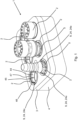
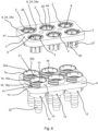
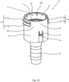
- connection device 1 for media lines in a perspective view.
- the connection device 1 has six insert parts 2, a cover plate 3 and a base plate 4.
- the cover plate 3 is connected to the base plate 4, in particular screwed to the base plate 4.
- the cover plate 3 is additionally positively locked to the base plate 4, in particular at least in a pre-locking position. For example, different connection plugs 5 are inserted into two of the insert parts 2 - the insert parts 2 shown at the front left.
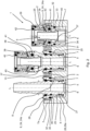
- Fig.2 shows the embodiment of a connection device 1 according to Fig.1 in section view, namely according to Fig.1 through the front row of insert parts 2.
- Six connection openings 7 are provided in the base plate 4, which in this embodiment are formed directly in the base plate 7.
- the base plate 7 is a valve plate.
- the connection openings 7 open into fluid channels 6, wherein the connection openings 7 are designed to at least partially accommodate insert parts 2.
- the insert parts 2 each have a connection interface 8 for establishing a connection to a media line.
- the insert part 2 shown on the far right is an insert part 2 that can directly connect a line and is described in more detail elsewhere.
- the connector plug 5 shown in the middle comprises a connection interface 8 which is designed according to the connection interface 8 of the insert part 2, which in Fig. 2 shown on the far right.
- the insert parts 2 are detachably inserted at least partially into the connection openings 7 and are held in position by the cover plate 3, which is connected to the base plate 4.
- the insert parts 2 also have at least one connecting means 9 with which the cover plate 3 can be connected to the insert part 2.
- the connecting means 9, namely the insert locking means 24, is designed here as two locking hooks 24a, which lock positively to the cover plate 3.
- Fig.3 shows a section through the Fig.1 rear row of connection openings 7 with insert parts 2.
- the insert parts 2 are connected to the The cover plate 3 connected to the base plate 4 is held in the connection openings 7.
- the locking hooks 24a are positively locked to the cover plate 3.
- the insert parts 2 are designed completely identically.
- the insert parts 2 rest with a holding projection 29 on the end face 7a surrounding the connection opening 7.
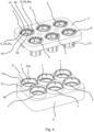
- Fig.4 shows a partial exploded view of a cover plate 3 with insert parts 2 attached to it in a form-fitting manner and the base plate 4, in which the connection openings 7 are formed directly in the base plate 4. Furthermore, the base plate 4 has according to Fig.4 six sleeve-like sections 10 which at least partially surround the connection openings 7. All connection openings 7 with the sleeve-like, collar-like protruding sections 10 are identically designed.
- the insert parts 2 which are positively locked to the cover plate 3 in this illustration are identically designed.
- the insert part 2 in the connection opening 7 at the front right is, in comparison to the Fig.1 and Fig.2 been replaced by another.
- Fig.5 shows the embodiment according to Fig.4 in the assembled state, namely when the cover plate 3 is connected to the base plate 4.
- the insert parts 2 are flush with the surface of the cover plate 3, only the locking hooks 24a protrude slightly. All insert parts 2 inserted into the connection openings 7 are identical.
- the cover plate 3 is screwed to the base plate 4.
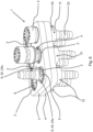
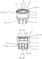
- Fig.6 shows an embodiment of a connection device 1 for media lines in a perspective view.
- the connection device 1 has six connection openings 7, a cover plate 3 and a base plate 4.
- an insert part 2 that is different from the other insert parts 2 is inserted at the front right.
- a connector plug 5 with the connection interfaces 8 (see Fig.8 ) tied together.
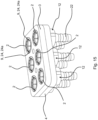
- Fig.7 shows the base plate 4 according to the embodiment of the Fig.6 , namely that the base plate 4 in this embodiment has six coupling recesses 11, and that a coupling element 12 is inserted into each of the coupling recesses 11 and connected to the base plate 4.
- the coupling elements 12 are completely identical, whereby only three are shown here as an example.
- the coupling elements 12 are according to Fig.7 from below into the coupling recesses 11.
- Fig.8 shows the coupling elements 12 mounted in the coupling recesses 11 of the base plate 4, namely positively locked in place, according to Fig.7 .
- Each coupling recess 11 has two oppositely arranged, radially flexible locking elements 13, which form a positive connection with the coupling element 12, in particular a locking element formed on the coupling element 12 and in the Fig.7 and 8
- the locking elements 13 are curved around the central axis of the coupling recess 11 and extend almost over the entire thickness of the base plate 4 (see in particular Fig.7 ).
- the counter-latching means 14 comprises a first latching projection 15 with a first latching region 15a extending partially around the circumference and a second latching projection 16 with a first latching region 16a extending at least partially around the circumference.
- the counter-latching means 14, namely the latching projections 15, 16 are arranged on an outer circumference 20a of the coupling elements 12, in particular of the coupling base body 20.
- the first locking projection 15 has a second locking region 15b and the second locking projection 16 has a second locking region 16b opposite one another on the circumference.
- Fig.7 further shows that the coupling elements 12 each have two oppositely arranged, radially flexible plate locking means 17, each of which has an insertion bevel 19 inclined in the direction of a second end side 18 facing away from the access of the connection opening 7.
- the access to the connection opening 7 is formed on the first end side 21 and the fluid channel 6 with a connection mandrel 22 is formed on the second end side 18.
- On the first end side 21, in the edge area of the connection opening 7, a plurality of leakage recesses 23a oriented parallel to the longitudinal direction are arranged on the coupling elements 12, which allow fluid to escape if the insert part 2 is not inserted correctly or if the seal is faulty.
- the coupling elements 12 have further leakage recesses 23b on the inner circumference 34 below the stop surface 31 arranged in the connection opening 7, which are also oriented parallel to the longitudinal axis L - in the longitudinal direction (see in particular Fig. 12 , Fig. 14 and Fig. 16 ).
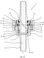
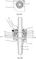
- Fig.9 shows a section through the connection device 1 according to Fig.6 , namely in the area of the connection opening 7 shown at the front left.
- Fig.10 shows a section in the area of the same connection opening 7, but rotated by 90° around the longitudinal axis L.
- Fig.9 shows that the plate locking means 17 are in engagement with the base plate 4. Furthermore, the insert part 2 is held in the connection opening 7 by the cover plate 3, in that the cover plate 3 is connected to the base plate 4.
- Fig.10 shows that the radially flexible locking elements 13 in the coupling recess 11 act from below against the second locking projection 16 of the counter-locking means 14 and thus the coupling element 12 between flexible Locking elements 13 and the plate locking means 17 are held on the base plate 4.
- the locking elements 13 are angled in their end regions so that they can lock both with the first locking projection 15 and with the second locking projection 16.
- Fig. 11 shows - as already stated - an embodiment of a connection device 1 for media lines in a perspective view.
- Fig. 12 shows a section through the embodiment according to Fig. 11 , namely by the front row of insert parts 2.
- the insert parts 2 and connector plugs 5 are identical to the embodiment in Fig. 2
- the base plate 4 has Fig.
- Fig. 2 , Fig.3 , Fig.9 , Fig.10 , Fig. 12 , Fig. 17a , Fig. 17b and 23 show further that the insert parts 2 preferably have a sleeve-like insert part base body 25 and, on a first end side 26, eight radially flexible holding arms 27 extending from the insert part base body 25 and formed in the longitudinal direction, so that the Connection interface 8 is designed as a plug receptacle for interaction with a connection plug 5 of a media line.
- a locking projection 28 is formed on each holding arm 27, the locking projections 28 on two adjacent holding arms 27 having different distances in the longitudinal direction from the first end side 26 of the insert part base body 25, so that locking projections 28a of the first type and locking projections 28b of the second type are present.
- the locking projections 28a of the first type have a smaller distance in the longitudinal direction than the locking projections 28b of the second type.
- Insert parts 2 or the insert part base bodies 25 have a first circumferentially arranged holding projection 29, which is provided on the one hand for axial positioning within the connection opening 7, and on the other hand for positive locking with the cover plate 3 (see in particular Fig.3 , Fig.9 , Fig.10 and Fig. 12 ).
- the insert part 2 further comprises an insert locking means 24, in particular a radially spring-elastic one, as a connecting means 9, which is designed as two locking hooks 24a.
- the locking hooks 24a interact in a form-fitting manner with the cover plate 3.
- the insert part 2 additionally has a second circumferentially arranged retaining projection 30, which also serves to engage with a stop surface 31 arranged in the connection opening 7 - see Fig.10 - serves.
- a seal 32 in particular an O-ring seal, is provided in a groove 33 on the outer circumference of the insert part 2, which rests in the connection opening 7 in the assembled state.
- the seal 32 is arranged on a shoulder 35 and is secured against loss before assembly, in particular by a projection 36.
- the insert part 2 shown on the far right is used for direct connection to a line (not shown).
- the insert parts 2 each have a mandrel-like support section 37, which is intended for at least partial entry into the end section of a line, and a toothed ring 38 for fixing the line in place by the toothed ring 38 clamping the line around its circumference.
- the insert part 2 also comprises a release element 39, which can be moved parallel to the longitudinal direction of the toothed ring 38 and is used to release the clamping between the toothed ring 38 and a line by elastically deforming the toothed ring 38.
- the support section 37, the toothed ring 38 and the release element 39 are held in the insert part base body 25.
- the insert part 2 further comprises a guide body 40 which is locked to the insert part base body 25 and can be fully inserted into the connection opening 7.
- the guide body 40 also has the groove 33 for the seal 32.
- the insert part 2 also has a main seal 41 which can be placed on the line and a dirt seal 42 arranged on the inlet side. The main seal 41 is held in position by an insert ring 43 which also clamps the toothed ring 38 against the insert part base body 25.
- the insert part 2 or the insert part base body 25 has a plurality of circumferentially arranged first leakage recesses 45 on a first inner circumference 44 of the connection interface 8 and a plurality of circumferentially arranged second leakage recesses 47 in a second inner circumference 46 to form a leakage path.
- the leakage recesses 45, 47 are preferably formed parallel to the longitudinal axis L.
- the cover plate 3 is in a position by means of two cover plate locking means 48, which in this embodiment are designed as flexible locking arms 48c.
- Pre-locking position with the base plate 4 positively locked see Fig. 19 ).
- defined leakage paths are formed.
- a final connection between cover plate 3 and base plate 4 is made by screwing, which also closes the leakage paths.
- the flexible locking arms 48c therefore serve to temporarily connect the cover plate 3 and the base plate 4 for assembly purposes.
- cover plate locking means 48 in this embodiment are designed as flexible locking arms 48a with a rigid frame 48b (see Fig. 19 ).
- the locking arms 48a serve to connect the connection device 1 in an installation situation, for example in a recess in a wall on a vehicle (not shown).
- the locking arms 48a can lock positively into the wall.
- the insert parts 2 have a plurality of first leakage recesses 45 on a first inner circumference 44 and a plurality of second leakage recesses 47 on a second inner circumference 46.
- Fig. 19 shows an embodiment of a connecting device 1 in a partially exploded view, which, with the exception of the insert part 2 at the front right, is like the embodiment according to Fig. 18
- the cover plate 3 has six coupling recesses 11 into which insert parts 2 are inserted.
- the cover plate 3 can be temporarily locked to the base plate 4 by means of the cover plate locking means 48 designed as flexible locking arms 48c.
- the cover plate locking means 48 arranged on the long side are designed as flexible locking arms 48a with a rigid frame 48b and serve to fasten the connection device 1 in an installation situation.
- the base plate 4 has a radially flexible locking element 13 in the coupling recess 11, which locks positively with the coupling element 12.
- two flexible coupling locking means 49 in the form of of locking arms.
- the coupling locking means 49 are arranged offset from one another.
- the coupling locking means 49 of a coupling recess 11 are arranged on two different sides of a plane which contains the three central axes of the front coupling recesses 11.
- the coupling locking means 49 each have a locking edge 50 which is oriented essentially tangentially to the coupling recess 11.
- the base plate 4 has a flexible locking means 51 on each coupling recess 11, here in the form of a radially flexible locking arm. In the assembled state, a coupling element 12 is consequently fixed in the coupling recess 11 by the locking arm 13, the coupling locking means 49 and the locking means 51.
- the coupling elements 12 of the Fig. 18 , Fig. 19 , Fig. 20b and Fig. 21 have according to Fig. 22 via a partially circumferential closing edge 52, a locking edge 53 and a guide edge 54.
- the closing edge 52, the locking edge 53 and the guide edge 54 have different distances from the front edge 7a along the longitudinal axis L.
- the closing edge 52 serves to at least partially close the coupling recess 11.
- the locking means 51 cooperates with the locking edge 53 in a form-fitting manner.
- the coupling locking means 49 which are arranged offset from one another, are provided with their locking edges 50, in particular according to Fig. 20 , in the assembled state with the counter-locking means 14, in particular with a locking projection 55b and a locking projection 55c of the counter-locking means 14.
- Fig. 20a is a partial plan view of the embodiment according to Fig. 18 , especially that of insert part 2 at the front left.
- Fig. 20b shows the positive interaction of the locking edges 50, the coupling locking means 49 and the locking projections 55c and 55b.
- the insert part 2 is on the cover plate 3 held, is introduced into the connection opening 7 of the coupling element 12 and rests against the end face 7a of the coupling element 12.
- a connection plug 5 is introduced into the insert part 2 and is held by the locking projections 28.
- the coupling element 12 has been introduced into the base plate 4 from below, with the coupling base body 20 in front, and locked into place.
- Fig. 21 shows a base plate 4 with six mounted coupling elements 12, each of which is held in the coupling recesses 11 by positive locking of the coupling locking means 49 with two locking projections 55b, 55c of the counter-locking means 14 and the locking means 51 with the second locking edge 53.
- the coupling locking means 49 are arranged offset from one another so that they lock with the locking projections 55b, 55c arranged diagonally to one another.
- a cover plate 3 with insert elements 2 according to Fig. 19 can be mounted and screwed for final fastening.
- the coupling locking means 49 are arranged offset from one another in such a way that, in the assembled state, they interact with a front locking projection 55b and a diagonally opposite, rear locking projection 55c.
- Fig. 22 shows an embodiment of a coupling element 12 according to the Fig. 18 to Fig. 21 .
- the coupling element 12 On its outer circumference 20a, the coupling element 12 has a counter-latching means 14 with four latching projections 55a, 55b, 55c, 55d.
- the latching projections 55a, 55b, 55c, 55d are arranged so that they are opposite one another in pairs and are arranged on a tangent or a secant to the coupling recess 11.
- the latching projections 55a, 55b, 55c, 55d extend so far from the outer circumferential surface 20a that the ends of the latching projections 55a, 55b, 55c, 55d arranged next to one another, namely the latching projections 55a and 55c as well as the latching projections 55b and 55d, each in a common, imaginary plane.
- the connecting mandrel 22 serves to connect the fluid channel 6 to a line (not shown).
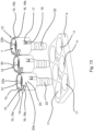
- Fig. 23 shows a further embodiment of an insert part 2 in a sectional side view. The insert part 2 is inserted into a coupling base body 20 of a coupling element 12, which is only partially shown.
- a connector plug 5 is inserted into the connection interface 8 of the insert part 2 and locked into the locking projections 28, 28b of the holding arms 27.
- the support element 56 extends over the entire width of the respective holding arm 27 and serves to support the holding arm on the coupling element 12 in the connection opening 7, in particular to prevent damage to the holding arm 27 in the event of a radial evasive movement.
- the radial deflection movement occurs in particular through or when operating pressure acts on the insert part 2, the connector plug 5 and the other components.
- the support element 56 rests against the inner wall of the coupling element 12 and influences the bending or deformation behavior of the holding arm 27.
- Some of the holding arms 27 also have a recess 57 on the first end side 26 of the insert part 2, which reduces the wall thickness of the holding arm 27 and thereby increases its flexibility.
Landscapes
- Engineering & Computer Science (AREA)
- General Engineering & Computer Science (AREA)
- Mechanical Engineering (AREA)
- Quick-Acting Or Multi-Walled Pipe Joints (AREA)
Claims (20)
- Dispositif de raccordement (1) pour des conduites de fluide avec au moins une pièce d'insertion (2), au moins une plaque de recouvrement (3), au moins une plaque de base (4), au moins un canal de fluide (6) et au moins une ouverture de raccordement (7) pour recevoir au moins partiellement la pièce d'insertion (2), la pièce d'insertion (2) présentant une interface de liaison (8) pour établir une liaison avec une conduite de fluide, la pièce d'insertion (2) pouvant être introduite de manière amovible au moins partiellement dans l'ouverture de raccordement (7), la plaque de recouvrement (3) pouvant être reliée à la plaque de base (4), et l'ouverture de raccordement (7) s'étendant au moins partiellement dans la plaque de base (4),
la pièce d'insertion (2) présentant au moins un moyen de liaison (9) pour l'encliquetage par complémentarité de forme avec la plaque de recouvrement (3), le moyen de liaison (9) étant réalisé sous la forme d'au moins deux crochets d'encliquetage (24a), les crochets d'encliquetage (24a) étant eux-mêmes ou en combinaison avec au moins une partie de la pièce d'insertion (2) radialement élastiques, et l'ouverture de raccordement (7) présentant sur sa périphérie intérieure, sur un premier côté d'extrémité, une pluralité d'évidements de fuite (23a) s'étendant dans la direction longitudinale. - Dispositif de raccordement (1) selon la revendication 1,
caractérisé en ce que
l'ouverture de raccordement (7) est réalisée dans la plaque de base (4), de préférence que la plaque de base (4) présente au moins une section (10) en forme de douille entourant partiellement l'ouverture de raccordement (7), de manière particulièrement préférée que la plaque de base (4) fasse partie d'un ensemble, par exemple d'un bloc de vannes ou d'un distributeur. - Dispositif de raccordement (1) selon la revendication 1,
caractérisé en ce que
la plaque de base (4) présente au moins un évidement d'accouplement (11), en ce qu'un élément d'accouplement (12) est inséré dans l'évidement d'accouplement (11) et est relié à la plaque de base (4), et en ce que l'ouverture de raccordement (7) est formée dans l'élément d'accouplement (12), en particulier en ce que l'élément d'accouplement (12) forme une section en forme de douille (10), avantageusement en ce que la plaque de base (4) présente dans l'évidement d'accouplement (11) au moins un élément d'encliquetage (13) radialement flexible, en particulier deux éléments d'encliquetage (13) radialement flexibles disposés en face l'un de l'autre, et en ce que l'élément d'encliquetage (13) permet d'établir une liaison par complémentarité de forme avec l'élément d'accouplement (12), de préférence en ce que l'élément d'encliquetage (13) est coudé dans une zone d'extrémité libre. - Dispositif de raccordement (1) selon la revendication 3,
caractérisé en ce que
la plaque de base (4) présente au niveau de l'évidement d'accouplement (11) au moins un moyen d'encliquetage d'accouplement flexible (49), en particulier présente au moins deux moyens d'encliquetage d'accouplement (49), de préférence que le moyen d'encliquetage d'accouplement (49) présente au moins une arête d'encliquetage (50) disposée tangentiellement à l'évidement d'accouplement (11). - Dispositif de raccordement (1) selon l'une des revendications 3 ou 4, caractérisé en ce que
la plaque de base (4) présente au moins un moyen de blocage flexible (51) au niveau de l'évidement d'accouplement (11). - Dispositif de raccordement (1) selon l'une quelconque des revendications 1 à 5,
caractérisé en ce que
la plaque de recouvrement (3) présente au moins un moyen d'encliquetage de plaque de recouvrement (48), de préférence une pluralité de moyens d'encliquetage de plaque de recouvrement (48), pour l'assemblage avec la plaque de base (4) et/ou pour l'assemblage du dispositif de raccordement (1) en situation de montage. - Dispositif de raccordement (1) selon l'une des revendications 3 à 6, caractérisé en ce que
un moyen de contre-encliquetage (14) est formé sur une périphérie extérieure (20a) de l'élément d'accouplement (12), en particulier en ce que le moyen de contre-encliquetage (14) présente une première saillie d'encliquetage (15) avec une première zone d'encliquetage (15a) s'étendant au moins sur une partie de la périphérie, et en ce que la première saillie d'encliquetage (15) présente une première distance dans le sens longitudinal par rapport à une surface frontale (7a) entourant l'ouverture de raccordement (7), de préférence en ce que la première saillie d'encliquetage (15) présente une première hauteur radiale, de manière particulièrement préférée en ce que la première saillie d'encliquetage (15) présente une deuxième zone d'encliquetage (15b) opposée sur la circonférence à la première zone d'encliquetage (15a), de préférence en ce que le moyen de contre-encliquetage (14) présente une deuxième saillie d'encliquetage (16) avec une première zone d'encliquetage (16a) s'étendant au moins partiellement sur la circonférence, et en ce que la deuxième saillie d'encliquetage (16) présente une deuxième distance dans la direction longitudinale par rapport à une surface frontale (7a) entourant l'ouverture de raccordement (7), de préférence, la deuxième saillie d'encliquetage (16) présente une deuxième hauteur radiale, de manière particulièrement préférée, la deuxième saillie d'encliquetage (16) présente une deuxième zone d'encliquetage (16b) opposée sur la circonférence à la première zone d'encliquetage (16a). - Dispositif de raccordement (1) selon la revendication 7,
caractérisé en ce que
le moyen de contre-encliquetage (14) présente au moins deux saillies d'encliquetage (55a, 55b, 55c, 55d), en particulier au moins quatre saillies d'encliquetage (55a, 55b, 55c, 55d), de préférence que deux saillies d'encliquetage (55a, 55b, 55c, 55d) sont respectivement disposées en face l'une de l'autre de manière décalée par rapport à l'axe longitudinal (L) de l'élément de couplage (12). - Dispositif de raccordement (1) selon l'une quelconque des revendications 3 à 8,
caractérisé en ce que
l'élément d'accouplement (12) présente sur une périphérie extérieure (20a) au moins une arête d'encliquetage (53), en particulier au moins partiellement périphérique, de préférence présente en plus au moins une arête de fermeture (52) et/ou au moins une arête de guidage (54), de préférence encore que l'arête d'encliquetage (53), l'arête de fermeture (52) et l'arête de guidage (54) présentent des distances différentes par rapport à une face frontale (7a) de l'élément d'accouplement (12). - Dispositif de raccordement (1) selon l'une quelconque des revendications 3 à 9,
caractérisé en ce que
l'élément d'accouplement (12) présente au moins un moyen d'encliquetage à plaque (17) radialement flexible sur sa périphérie extérieure (20a), et en ce que le moyen d'encliquetage à plaque (17) présente un biseau d'introduction (19), et en ce que le biseau d'introduction (19) est incliné en direction d'un deuxième côté d'extrémité (18) opposé à l'accès de l'ouverture de raccordement (7), en particulier en ce que l'élément d'accouplement (12) présente deux moyens d'encliquetage à plaque (17) identiques, disposés en opposition sur la périphérie. - Dispositif de raccordement (1) selon l'une quelconque des revendications 3 à 10,
caractérisé en ce que
que l'élément d'accouplement (12) présente un corps de base d'accouplement (20) de type cylindrique, que l'ouverture de raccordement (7) est formée à l'intérieur du corps de base d'accouplement (20), que l'accès à l'ouverture de raccordement (7) est formé sur un premier côté d'extrémité (21) et que le canal de fluide (6) est formé sur un deuxième côté d'extrémité (18) avec un moyen de raccordement, en particulier un mandrin de raccordement (22). - Dispositif de raccordement (1) selon l'une des revendications 3 à 10, caractérisé en ce que
l'ouverture de raccordement (7) présente sur sa périphérie intérieure, sur le premier côté d'extrémité (21), une pluralité d'évidements de fuite (23a) s'étendant dans la direction longitudinale, et/ou en ce que l'ouverture de raccordement (7) présente au moins un épaulement entre deux diamètres intérieurs différents, et en ce qu'une pluralité d'évidements de fuite (23b) s'étendant dans la direction longitudinale est prévue sur la périphérie intérieure sur le plus petit diamètre. - Dispositif de raccordement (1) selon l'une des revendications 1 à 12, caractérisé en ce que
la pièce d'insertion (2) présente au moins un moyen d'encliquetage d'insertion (24), en particulier radialement élastique, le moyen d'encliquetage d'insertion (24) pouvant être encliqueté par complémentarité de forme avec la plaque de recouvrement (3), en particulier en ce que le moyen d'encliquetage d'insertion (24) est réalisé sous la forme d'au moins deux crochets d'encliquetage (24a), et en ce que les deux crochets d'encliquetage (24a) sont disposés sur la périphérie en étant opposés l'un à l'autre. - Dispositif de raccordement selon l'une quelconque des revendications 1 à 13, caractérisé en ce que
la pièce d'insertion (2) présente au moins un corps de base de pièce d'insertion (25) en forme de douille, en ce que le corps de base de pièce d'insertion (25) présente sur un premier côté d'extrémité (26) au moins deux bras de retenue (27) flexibles radialement, réalisés dans la direction longitudinale à partir du corps de base de pièce d'insertion (25), de sorte que l'interface de liaison (8) est réalisée sous forme de logement de fiche pour la liaison avec une fiche de raccordement (5) d'une conduite de fluide, en particulier en ce qu'au moins une saillie d'encliquetage (28) est formée sur chacun des bras de retenue (27), de préférence en ce qu'au moins un bras de retenue (27) présente au moins un élément d'appui (56) et/ou un évidement (57) sur le côté opposé à la saillie d'encliquetage (28), de préférence en ce que plus de deux bras de retenue (27) sont formés, et en ce que les saillies d'encliquetage (28) sur deux bras de retenue (27) juxtaposés présentent une distance différente dans la direction longitudinale par rapport au premier côté d'extrémité (26), en particulier de sorte qu'une position de pré-encliquetage et une position d'encliquetage complet peuvent être réalisées pour une fiche de raccordement (5) incorporable. - Dispositif de raccordement (1) selon l'une quelconque des revendications 1 à 14,
caractérisé en ce que
la pièce d'insertion (2) présente une première saillie de retenue (29) disposée sur la périphérie pour l'appui sur une surface frontale (7a) d'une ouverture de raccordement (7), et/ou une deuxième saillie de retenue (30) disposée sur la périphérie pour l'appui sur une surface de butée (31) disposée dans l'ouverture de raccordement (7). - Dispositif de raccordement (1) selon l'une quelconque des revendications 1 à 15,
caractérisé en ce que
la pièce d'insertion (2) est disposée sensiblement à fleur de la plaque de recouvrement (3). - Dispositif de raccordement (1) selon l'une quelconque des revendications 1 à 16,
caractérisé en ce que
la pièce d'insertion (2) présente au moins un joint d'étanchéité (32) sur une périphérie extérieure, en particulier en ce que le joint d'étanchéité (32) est disposé dans une rainure périphérique (33) dans la pièce d'insertion (2). - Dispositif de raccordement (1) selon l'une quelconque des revendications 1 à 17,
caractérisé en ce que
la pièce d'insertion (3) présente au moins une section de support (37) en forme de mandrin pour l'entrée dans une conduite, au moins une bague dentée (38) pour la fixation d'une conduite, ainsi qu'au moins un élément de desserrage (39). - Dispositif de raccordement (1) selon l'une quelconque des revendications 1 à 18,
caractérisé en ce que
la pièce d'insertion (2) présente sur une première circonférence intérieure (44) de l'interface de liaison (8) une pluralité de premiers évidements de fuite (45) disposés sur la circonférence, et/ou en ce que la pièce d'insertion (2) présente dans une deuxième circonférence intérieure (46) une pluralité de deuxièmes évidements de fuite (47) disposés sur la circonférence. - Dispositif de raccordement (1) selon l'une quelconque des revendications 1 à 19,
caractérisé en ce que
au moins quatre, de préférence au moins six ouvertures de raccordement (7) sont présentes.
Applications Claiming Priority (3)
| Application Number | Priority Date | Filing Date | Title |
|---|---|---|---|
| DE102017106676.4A DE102017106676A1 (de) | 2017-03-28 | 2017-03-28 | Anschlussvorrichtung für Medienleitungen |
| DE202017107491.9U DE202017107491U1 (de) | 2017-03-28 | 2017-12-08 | Anschlussvorrichtung für Medienleitungen |
| PCT/EP2018/057950 WO2018178166A1 (fr) | 2017-03-28 | 2018-03-28 | Dispositif de raccordement pour conduites de fluide |
Publications (2)
| Publication Number | Publication Date |
|---|---|
| EP3601867A1 EP3601867A1 (fr) | 2020-02-05 |
| EP3601867B1 true EP3601867B1 (fr) | 2024-09-11 |
Family
ID=62910404
Family Applications (1)
| Application Number | Title | Priority Date | Filing Date |
|---|---|---|---|
| EP18714492.8A Active EP3601867B1 (fr) | 2017-03-28 | 2018-03-28 | Dispositif de raccordement pour conduites de fluide |
Country Status (3)
| Country | Link |
|---|---|
| EP (1) | EP3601867B1 (fr) |
| DE (2) | DE102017106676A1 (fr) |
| WO (1) | WO2018178166A1 (fr) |
Families Citing this family (5)
| Publication number | Priority date | Publication date | Assignee | Title |
|---|---|---|---|---|
| DE102018107507A1 (de) | 2018-03-28 | 2019-10-02 | Voss Automotive Gmbh | "Anschlussvorrichtung für Medienleitungen" |
| WO2023198636A1 (fr) * | 2022-04-13 | 2023-10-19 | Voss Automotive Gmbh | Raccord multiple pour lignes de fluides |
| DE102022122296A1 (de) * | 2022-09-02 | 2024-03-07 | Voss Automotive Gmbh | Mehrfachkupplung für Medienleitungen und Kupplungsträger |
| DE102023127955A1 (de) * | 2023-10-12 | 2025-04-17 | Bürkert Werke GmbH & Co. KG | Ventilbaugruppe und Montageplatte mit einer Ventilbaugruppe |
| DE102024108834A1 (de) * | 2024-03-27 | 2025-10-02 | Voss Automotive Gmbh | "Kupplung für Medienleitungen und plattenartiger Kupplungsträger" |
Citations (2)
| Publication number | Priority date | Publication date | Assignee | Title |
|---|---|---|---|---|
| EP0999398A1 (fr) * | 1998-11-05 | 2000-05-10 | Armaturenfabrik Hermann Voss GmbH + Co. KG | Raccord à fiche |
| DE102016106250A1 (de) * | 2016-04-06 | 2016-11-03 | Miele & Cie. Kg | Schlauchverbinder für ein Haushaltgerät und Haushaltgerät |
Family Cites Families (9)
| Publication number | Priority date | Publication date | Assignee | Title |
|---|---|---|---|---|
| DE8908944U1 (de) * | 1989-07-22 | 1989-09-14 | Armaturenfabrik Hermann Voss GmbH + Co, 5272 Wipperfürth | Rohrleitungsmehrfachkupplung |
| WO2002065010A2 (fr) * | 2001-02-13 | 2002-08-22 | Smc Corporation Of America | Couplage pneumatique |
| DE102005047835B4 (de) * | 2004-10-06 | 2014-07-17 | Voss Automotive Gmbh | Steckverbindung für Druckmittelsysteme |
| DE202005001153U1 (de) * | 2005-01-24 | 2006-06-08 | Voss Automotive Gmbh | Kupplungseinrichtung für Medienleitungen |
| US7540539B2 (en) * | 2005-08-03 | 2009-06-02 | Eagle Industry Co., Ltd. | Pipe joint |
| DE202005020263U1 (de) * | 2005-12-23 | 2007-04-26 | Voss Automotive Gmbh | Mehrfachkupplung für Medienleitungen |
| DE102012108791A1 (de) * | 2012-09-18 | 2014-03-20 | Voss Automotive Gmbh | Bausystem für eine Anschlussvorrichtung für Medienleitungen |
| DE102012110935A1 (de) * | 2012-11-14 | 2014-05-15 | Voss Automotive Gmbh | Kupplungseinrichtung für Medienleitungen |
| DE102015110124A1 (de) * | 2015-06-24 | 2016-12-29 | Voss Automotive Gmbh | Anschlussvorrichtung zum lösbaren Anschluss von Kunststoff-Rohrleitungen |
-
2017
- 2017-03-28 DE DE102017106676.4A patent/DE102017106676A1/de active Pending
- 2017-12-08 DE DE202017107491.9U patent/DE202017107491U1/de active Active
-
2018
- 2018-03-28 WO PCT/EP2018/057950 patent/WO2018178166A1/fr not_active Ceased
- 2018-03-28 EP EP18714492.8A patent/EP3601867B1/fr active Active
Patent Citations (2)
| Publication number | Priority date | Publication date | Assignee | Title |
|---|---|---|---|---|
| EP0999398A1 (fr) * | 1998-11-05 | 2000-05-10 | Armaturenfabrik Hermann Voss GmbH + Co. KG | Raccord à fiche |
| DE102016106250A1 (de) * | 2016-04-06 | 2016-11-03 | Miele & Cie. Kg | Schlauchverbinder für ein Haushaltgerät und Haushaltgerät |
Also Published As
| Publication number | Publication date |
|---|---|
| DE102017106676A1 (de) | 2018-10-04 |
| WO2018178166A1 (fr) | 2018-10-04 |
| DE202017107491U1 (de) | 2018-07-02 |
| EP3601867A1 (fr) | 2020-02-05 |
Similar Documents
| Publication | Publication Date | Title |
|---|---|---|
| EP3601867B1 (fr) | Dispositif de raccordement pour conduites de fluide | |
| EP3149384B1 (fr) | Raccord enfichable pour conduites de fluide, muni d'une douille d'adaptation intérieure | |
| EP0965014B1 (fr) | Element d'assemblage et de raccordement pour tubes ondules | |
| EP2649689B1 (fr) | Dispositif pour fixer un câble sur un raccord de départ de câble | |
| DE3817472C2 (fr) | ||
| EP4127543B1 (fr) | Raccord de type enfichable ayant un verrouillage de préassemblage | |
| EP2593994B1 (fr) | Boîtier, en particulier pour un connecteur de câble électrique | |
| WO2010119083A2 (fr) | Cheminement de cable | |
| EP0781386B1 (fr) | Raccord pour la piece d'accouplement des tuyaux d'un appareil de nettoyage a haute pression | |
| EP1841995B1 (fr) | Dispositif de couplage de conduites fluidiques | |
| WO2019048602A1 (fr) | Connecteur enfichable comprenant des crochets de verrouillage servant à fixer son support de contact dans son boîtier extérieur | |
| EP1653141B1 (fr) | Dispositif de connection et dispositif de filtrage avec un tel dispositif de connection | |
| DE4205142C1 (fr) | ||
| EP4405606B1 (fr) | Raccord mâle à verrouillage de pré-assemblage | |
| EP3064849B1 (fr) | Systeme de distribution, en particulier diffuseur d'air | |
| DE102019132178A1 (de) | Ventilinsel für eine Hydraulikanordnung und Hydraulikanordnung mit Ventilinsel | |
| EP4508354A1 (fr) | Raccord multiple pour lignes de fluides | |
| EP3775658A1 (fr) | Dispositif de raccordement pour conduites de fluide | |
| EP1963728B1 (fr) | Raccord | |
| EP3557108B1 (fr) | Dispositif de raccordement pour conduites de fluide | |
| DE102017129559B4 (de) | Anschlusskopf für eine Filterkerze, Set mit einem Anschlusskopf sowie Filterkerze | |
| EP1801485B1 (fr) | Raccord multiple pour tubes ou tuyaux | |
| DE4022769C2 (de) | Rohrleitungsmehrfachkupplung | |
| DE102015226536A1 (de) | Kabelverschraubung | |
| DE102009047957A1 (de) | Vorrichtung zum Verbinden von zwei Bauteilen |
Legal Events
| Date | Code | Title | Description |
|---|---|---|---|
| STAA | Information on the status of an ep patent application or granted ep patent |
Free format text: STATUS: UNKNOWN |
|
| STAA | Information on the status of an ep patent application or granted ep patent |
Free format text: STATUS: THE INTERNATIONAL PUBLICATION HAS BEEN MADE |
|
| PUAI | Public reference made under article 153(3) epc to a published international application that has entered the european phase |
Free format text: ORIGINAL CODE: 0009012 |
|
| STAA | Information on the status of an ep patent application or granted ep patent |
Free format text: STATUS: REQUEST FOR EXAMINATION WAS MADE |
|
| 17P | Request for examination filed |
Effective date: 20190905 |
|
| AK | Designated contracting states |
Kind code of ref document: A1 Designated state(s): AL AT BE BG CH CY CZ DE DK EE ES FI FR GB GR HR HU IE IS IT LI LT LU LV MC MK MT NL NO PL PT RO RS SE SI SK SM TR |
|
| AX | Request for extension of the european patent |
Extension state: BA ME |
|
| RIN1 | Information on inventor provided before grant (corrected) |
Inventor name: HASBERG, MARKUS Inventor name: ROSOWSKI, EVELIN Inventor name: HAGEN, HARALD |
|
| DAV | Request for validation of the european patent (deleted) | ||
| DAX | Request for extension of the european patent (deleted) | ||
| STAA | Information on the status of an ep patent application or granted ep patent |
Free format text: STATUS: EXAMINATION IS IN PROGRESS |
|
| 17Q | First examination report despatched |
Effective date: 20210921 |
|
| GRAP | Despatch of communication of intention to grant a patent |
Free format text: ORIGINAL CODE: EPIDOSNIGR1 |
|
| STAA | Information on the status of an ep patent application or granted ep patent |
Free format text: STATUS: GRANT OF PATENT IS INTENDED |
|
| INTG | Intention to grant announced |
Effective date: 20240425 |
|
| GRAS | Grant fee paid |
Free format text: ORIGINAL CODE: EPIDOSNIGR3 |
|
| GRAA | (expected) grant |
Free format text: ORIGINAL CODE: 0009210 |
|
| STAA | Information on the status of an ep patent application or granted ep patent |
Free format text: STATUS: THE PATENT HAS BEEN GRANTED |
|
| AK | Designated contracting states |
Kind code of ref document: B1 Designated state(s): AL AT BE BG CH CY CZ DE DK EE ES FI FR GB GR HR HU IE IS IT LI LT LU LV MC MK MT NL NO PL PT RO RS SE SI SK SM TR |
|
| REG | Reference to a national code |
Ref country code: GB Ref legal event code: FG4D Free format text: NOT ENGLISH |
|
| REG | Reference to a national code |
Ref country code: CH Ref legal event code: EP |
|
| REG | Reference to a national code |
Ref country code: DE Ref legal event code: R096 Ref document number: 502018015118 Country of ref document: DE |
|
| REG | Reference to a national code |
Ref country code: IE Ref legal event code: FG4D Free format text: LANGUAGE OF EP DOCUMENT: GERMAN |
|
| P01 | Opt-out of the competence of the unified patent court (upc) registered |
Free format text: CASE NUMBER: APP_50599/2024 Effective date: 20240906 |
|
| REG | Reference to a national code |
Ref country code: LT Ref legal event code: MG9D |
|
| REG | Reference to a national code |
Ref country code: NL Ref legal event code: MP Effective date: 20240911 |
|
| PG25 | Lapsed in a contracting state [announced via postgrant information from national office to epo] |
Ref country code: GR Free format text: LAPSE BECAUSE OF FAILURE TO SUBMIT A TRANSLATION OF THE DESCRIPTION OR TO PAY THE FEE WITHIN THE PRESCRIBED TIME-LIMIT Effective date: 20241212 Ref country code: FI Free format text: LAPSE BECAUSE OF FAILURE TO SUBMIT A TRANSLATION OF THE DESCRIPTION OR TO PAY THE FEE WITHIN THE PRESCRIBED TIME-LIMIT Effective date: 20240911 |
|
| PG25 | Lapsed in a contracting state [announced via postgrant information from national office to epo] |
Ref country code: BG Free format text: LAPSE BECAUSE OF FAILURE TO SUBMIT A TRANSLATION OF THE DESCRIPTION OR TO PAY THE FEE WITHIN THE PRESCRIBED TIME-LIMIT Effective date: 20240911 |
|
| PG25 | Lapsed in a contracting state [announced via postgrant information from national office to epo] |
Ref country code: LV Free format text: LAPSE BECAUSE OF FAILURE TO SUBMIT A TRANSLATION OF THE DESCRIPTION OR TO PAY THE FEE WITHIN THE PRESCRIBED TIME-LIMIT Effective date: 20240911 |
|
| PG25 | Lapsed in a contracting state [announced via postgrant information from national office to epo] |
Ref country code: HR Free format text: LAPSE BECAUSE OF FAILURE TO SUBMIT A TRANSLATION OF THE DESCRIPTION OR TO PAY THE FEE WITHIN THE PRESCRIBED TIME-LIMIT Effective date: 20240911 |
|
| PG25 | Lapsed in a contracting state [announced via postgrant information from national office to epo] |
Ref country code: RS Free format text: LAPSE BECAUSE OF FAILURE TO SUBMIT A TRANSLATION OF THE DESCRIPTION OR TO PAY THE FEE WITHIN THE PRESCRIBED TIME-LIMIT Effective date: 20241211 Ref country code: ES Free format text: LAPSE BECAUSE OF FAILURE TO SUBMIT A TRANSLATION OF THE DESCRIPTION OR TO PAY THE FEE WITHIN THE PRESCRIBED TIME-LIMIT Effective date: 20240911 |
|
| PG25 | Lapsed in a contracting state [announced via postgrant information from national office to epo] |
Ref country code: RS Free format text: LAPSE BECAUSE OF FAILURE TO SUBMIT A TRANSLATION OF THE DESCRIPTION OR TO PAY THE FEE WITHIN THE PRESCRIBED TIME-LIMIT Effective date: 20241211 Ref country code: LV Free format text: LAPSE BECAUSE OF FAILURE TO SUBMIT A TRANSLATION OF THE DESCRIPTION OR TO PAY THE FEE WITHIN THE PRESCRIBED TIME-LIMIT Effective date: 20240911 Ref country code: HR Free format text: LAPSE BECAUSE OF FAILURE TO SUBMIT A TRANSLATION OF THE DESCRIPTION OR TO PAY THE FEE WITHIN THE PRESCRIBED TIME-LIMIT Effective date: 20240911 Ref country code: GR Free format text: LAPSE BECAUSE OF FAILURE TO SUBMIT A TRANSLATION OF THE DESCRIPTION OR TO PAY THE FEE WITHIN THE PRESCRIBED TIME-LIMIT Effective date: 20241212 Ref country code: FI Free format text: LAPSE BECAUSE OF FAILURE TO SUBMIT A TRANSLATION OF THE DESCRIPTION OR TO PAY THE FEE WITHIN THE PRESCRIBED TIME-LIMIT Effective date: 20240911 Ref country code: ES Free format text: LAPSE BECAUSE OF FAILURE TO SUBMIT A TRANSLATION OF THE DESCRIPTION OR TO PAY THE FEE WITHIN THE PRESCRIBED TIME-LIMIT Effective date: 20240911 Ref country code: BG Free format text: LAPSE BECAUSE OF FAILURE TO SUBMIT A TRANSLATION OF THE DESCRIPTION OR TO PAY THE FEE WITHIN THE PRESCRIBED TIME-LIMIT Effective date: 20240911 |
|
| PG25 | Lapsed in a contracting state [announced via postgrant information from national office to epo] |
Ref country code: NL Free format text: LAPSE BECAUSE OF FAILURE TO SUBMIT A TRANSLATION OF THE DESCRIPTION OR TO PAY THE FEE WITHIN THE PRESCRIBED TIME-LIMIT Effective date: 20240911 |
|
| PG25 | Lapsed in a contracting state [announced via postgrant information from national office to epo] |
Ref country code: PT Free format text: LAPSE BECAUSE OF FAILURE TO SUBMIT A TRANSLATION OF THE DESCRIPTION OR TO PAY THE FEE WITHIN THE PRESCRIBED TIME-LIMIT Effective date: 20250113 Ref country code: IS Free format text: LAPSE BECAUSE OF FAILURE TO SUBMIT A TRANSLATION OF THE DESCRIPTION OR TO PAY THE FEE WITHIN THE PRESCRIBED TIME-LIMIT Effective date: 20250111 |
|
| PG25 | Lapsed in a contracting state [announced via postgrant information from national office to epo] |
Ref country code: SM Free format text: LAPSE BECAUSE OF FAILURE TO SUBMIT A TRANSLATION OF THE DESCRIPTION OR TO PAY THE FEE WITHIN THE PRESCRIBED TIME-LIMIT Effective date: 20240911 Ref country code: RO Free format text: LAPSE BECAUSE OF FAILURE TO SUBMIT A TRANSLATION OF THE DESCRIPTION OR TO PAY THE FEE WITHIN THE PRESCRIBED TIME-LIMIT Effective date: 20240911 |
|
| PG25 | Lapsed in a contracting state [announced via postgrant information from national office to epo] |
Ref country code: EE Free format text: LAPSE BECAUSE OF FAILURE TO SUBMIT A TRANSLATION OF THE DESCRIPTION OR TO PAY THE FEE WITHIN THE PRESCRIBED TIME-LIMIT Effective date: 20240911 |
|
| PG25 | Lapsed in a contracting state [announced via postgrant information from national office to epo] |
Ref country code: CZ Free format text: LAPSE BECAUSE OF FAILURE TO SUBMIT A TRANSLATION OF THE DESCRIPTION OR TO PAY THE FEE WITHIN THE PRESCRIBED TIME-LIMIT Effective date: 20240911 Ref country code: PL Free format text: LAPSE BECAUSE OF FAILURE TO SUBMIT A TRANSLATION OF THE DESCRIPTION OR TO PAY THE FEE WITHIN THE PRESCRIBED TIME-LIMIT Effective date: 20240911 |
|
| PG25 | Lapsed in a contracting state [announced via postgrant information from national office to epo] |
Ref country code: IT Free format text: LAPSE BECAUSE OF FAILURE TO SUBMIT A TRANSLATION OF THE DESCRIPTION OR TO PAY THE FEE WITHIN THE PRESCRIBED TIME-LIMIT Effective date: 20240911 Ref country code: SK Free format text: LAPSE BECAUSE OF FAILURE TO SUBMIT A TRANSLATION OF THE DESCRIPTION OR TO PAY THE FEE WITHIN THE PRESCRIBED TIME-LIMIT Effective date: 20240911 |
|
| REG | Reference to a national code |
Ref country code: DE Ref legal event code: R097 Ref document number: 502018015118 Country of ref document: DE |
|
| PGFP | Annual fee paid to national office [announced via postgrant information from national office to epo] |
Ref country code: DE Payment date: 20250526 Year of fee payment: 8 |
|
| PG25 | Lapsed in a contracting state [announced via postgrant information from national office to epo] |
Ref country code: DK Free format text: LAPSE BECAUSE OF FAILURE TO SUBMIT A TRANSLATION OF THE DESCRIPTION OR TO PAY THE FEE WITHIN THE PRESCRIBED TIME-LIMIT Effective date: 20240911 |
|
| PLBE | No opposition filed within time limit |
Free format text: ORIGINAL CODE: 0009261 |
|
| STAA | Information on the status of an ep patent application or granted ep patent |
Free format text: STATUS: NO OPPOSITION FILED WITHIN TIME LIMIT |
|
| 26N | No opposition filed |
Effective date: 20250612 |
|
| PG25 | Lapsed in a contracting state [announced via postgrant information from national office to epo] |
Ref country code: SE Free format text: LAPSE BECAUSE OF FAILURE TO SUBMIT A TRANSLATION OF THE DESCRIPTION OR TO PAY THE FEE WITHIN THE PRESCRIBED TIME-LIMIT Effective date: 20240911 |
|
| PG25 | Lapsed in a contracting state [announced via postgrant information from national office to epo] |
Ref country code: MC Free format text: LAPSE BECAUSE OF FAILURE TO SUBMIT A TRANSLATION OF THE DESCRIPTION OR TO PAY THE FEE WITHIN THE PRESCRIBED TIME-LIMIT Effective date: 20240911 |
|
| REG | Reference to a national code |
Ref country code: CH Ref legal event code: H13 Free format text: ST27 STATUS EVENT CODE: U-0-0-H10-H13 (AS PROVIDED BY THE NATIONAL OFFICE) Effective date: 20251023 |
|
| PG25 | Lapsed in a contracting state [announced via postgrant information from national office to epo] |
Ref country code: LU Free format text: LAPSE BECAUSE OF NON-PAYMENT OF DUE FEES Effective date: 20250328 |
|
| GBPC | Gb: european patent ceased through non-payment of renewal fee |
Effective date: 20250328 |
|
| REG | Reference to a national code |
Ref country code: BE Ref legal event code: MM Effective date: 20250331 |
|
| PG25 | Lapsed in a contracting state [announced via postgrant information from national office to epo] |
Ref country code: GB Free format text: LAPSE BECAUSE OF NON-PAYMENT OF DUE FEES Effective date: 20250328 |
|
| PG25 | Lapsed in a contracting state [announced via postgrant information from national office to epo] |
Ref country code: BE Free format text: LAPSE BECAUSE OF NON-PAYMENT OF DUE FEES Effective date: 20250331 |
|
| PG25 | Lapsed in a contracting state [announced via postgrant information from national office to epo] |
Ref country code: CH Free format text: LAPSE BECAUSE OF NON-PAYMENT OF DUE FEES Effective date: 20250331 |
|
| PG25 | Lapsed in a contracting state [announced via postgrant information from national office to epo] |
Ref country code: IE Free format text: LAPSE BECAUSE OF NON-PAYMENT OF DUE FEES Effective date: 20250328 |
|
| PGFP | Annual fee paid to national office [announced via postgrant information from national office to epo] |
Ref country code: NO Payment date: 20260311 Year of fee payment: 9 |
|
| PGFP | Annual fee paid to national office [announced via postgrant information from national office to epo] |
Ref country code: FR Payment date: 20260311 Year of fee payment: 9 |