EP3601874B1 - Source de lumière pour augmenter la perception des couleurs chez les personnes souffrant d'une vision défectueuse des couleurs - Google Patents
Source de lumière pour augmenter la perception des couleurs chez les personnes souffrant d'une vision défectueuse des couleurs Download PDFInfo
- Publication number
- EP3601874B1 EP3601874B1 EP18717247.3A EP18717247A EP3601874B1 EP 3601874 B1 EP3601874 B1 EP 3601874B1 EP 18717247 A EP18717247 A EP 18717247A EP 3601874 B1 EP3601874 B1 EP 3601874B1
- Authority
- EP
- European Patent Office
- Prior art keywords
- lighting
- spectral
- light
- mode
- gap
- Prior art date
- Legal status (The legal status is an assumption and is not a legal conclusion. Google has not performed a legal analysis and makes no representation as to the accuracy of the status listed.)
- Active
Links
Images



Classifications
-
- F—MECHANICAL ENGINEERING; LIGHTING; HEATING; WEAPONS; BLASTING
- F21—LIGHTING
- F21V—FUNCTIONAL FEATURES OR DETAILS OF LIGHTING DEVICES OR SYSTEMS THEREOF; STRUCTURAL COMBINATIONS OF LIGHTING DEVICES WITH OTHER ARTICLES, NOT OTHERWISE PROVIDED FOR
- F21V23/00—Arrangement of electric circuit elements in or on lighting devices
- F21V23/04—Arrangement of electric circuit elements in or on lighting devices the elements being switches
- F21V23/0442—Arrangement of electric circuit elements in or on lighting devices the elements being switches activated by means of a sensor, e.g. motion or photodetectors
-
- F—MECHANICAL ENGINEERING; LIGHTING; HEATING; WEAPONS; BLASTING
- F21—LIGHTING
- F21V—FUNCTIONAL FEATURES OR DETAILS OF LIGHTING DEVICES OR SYSTEMS THEREOF; STRUCTURAL COMBINATIONS OF LIGHTING DEVICES WITH OTHER ARTICLES, NOT OTHERWISE PROVIDED FOR
- F21V23/00—Arrangement of electric circuit elements in or on lighting devices
- F21V23/04—Arrangement of electric circuit elements in or on lighting devices the elements being switches
-
- F—MECHANICAL ENGINEERING; LIGHTING; HEATING; WEAPONS; BLASTING
- F21—LIGHTING
- F21V—FUNCTIONAL FEATURES OR DETAILS OF LIGHTING DEVICES OR SYSTEMS THEREOF; STRUCTURAL COMBINATIONS OF LIGHTING DEVICES WITH OTHER ARTICLES, NOT OTHERWISE PROVIDED FOR
- F21V9/00—Elements for modifying spectral properties, polarisation or intensity of the light emitted, e.g. filters
- F21V9/40—Elements for modifying spectral properties, polarisation or intensity of the light emitted, e.g. filters with provision for controlling spectral properties, e.g. colour, or intensity
-
- H—ELECTRICITY
- H05—ELECTRIC TECHNIQUES NOT OTHERWISE PROVIDED FOR
- H05B—ELECTRIC HEATING; ELECTRIC LIGHT SOURCES NOT OTHERWISE PROVIDED FOR; CIRCUIT ARRANGEMENTS FOR ELECTRIC LIGHT SOURCES, IN GENERAL
- H05B45/00—Circuit arrangements for operating light-emitting diodes [LED]
- H05B45/20—Controlling the colour of the light
-
- A—HUMAN NECESSITIES
- A61—MEDICAL OR VETERINARY SCIENCE; HYGIENE
- A61N—ELECTROTHERAPY; MAGNETOTHERAPY; RADIATION THERAPY; ULTRASOUND THERAPY
- A61N5/00—Radiation therapy
- A61N5/06—Radiation therapy using light
- A61N2005/0658—Radiation therapy using light characterised by the wavelength of light used
- A61N2005/0662—Visible light
-
- F—MECHANICAL ENGINEERING; LIGHTING; HEATING; WEAPONS; BLASTING
- F21—LIGHTING
- F21W—INDEXING SCHEME ASSOCIATED WITH SUBCLASSES F21K, F21L, F21S and F21V, RELATING TO USES OR APPLICATIONS OF LIGHTING DEVICES OR SYSTEMS
- F21W2131/00—Use or application of lighting devices or systems not provided for in codes F21W2102/00-F21W2121/00
- F21W2131/40—Lighting for industrial, commercial, recreational or military use
- F21W2131/405—Lighting for industrial, commercial, recreational or military use for shop-windows or displays
-
- F—MECHANICAL ENGINEERING; LIGHTING; HEATING; WEAPONS; BLASTING
- F21—LIGHTING
- F21Y—INDEXING SCHEME ASSOCIATED WITH SUBCLASSES F21K, F21L, F21S and F21V, RELATING TO THE FORM OR THE KIND OF THE LIGHT SOURCES OR OF THE COLOUR OF THE LIGHT EMITTED
- F21Y2113/00—Combination of light sources
- F21Y2113/10—Combination of light sources of different colours
- F21Y2113/13—Combination of light sources of different colours comprising an assembly of point-like light sources
-
- F—MECHANICAL ENGINEERING; LIGHTING; HEATING; WEAPONS; BLASTING
- F21—LIGHTING
- F21Y—INDEXING SCHEME ASSOCIATED WITH SUBCLASSES F21K, F21L, F21S and F21V, RELATING TO THE FORM OR THE KIND OF THE LIGHT SOURCES OR OF THE COLOUR OF THE LIGHT EMITTED
- F21Y2115/00—Light-generating elements of semiconductor light sources
- F21Y2115/10—Light-emitting diodes [LED]
Definitions
- the invention relates to a lighting system and also to a retail lighting system comprising such lighting system.
- WO2015/184299 describes media and devices that exploit the possibility of encoding multiple channels of spatially structured information into single images, by exploiting temporal modulation of color and brightness, are proposed.
- Applications include relief of color blindness, producing images enriched with normally "invisible” information from infrared, ultraviolet, and polarization, and effectively adding new perceptible colors within the visible spectrum.
- this document describes a system comprising: at least one sensor configured to detect at least one characteristic of an object that is not perceptible to an unaided human observer, the at least one characteristic being described by at least one measurement; at least one processor in data communication with the sensor; one or more components executable by the at least one processor and collectively configured to: receive, from the at least one sensor, data descriptive of the object and the at least one measurement; and generate an enhanced image of the object including an attribute representative of the measurement that is perceptible by the human observer, that systematically varies over time, and that is localized and faithful to a non-enhanced image of the object.
- WO 2016/188755 A1 discloses a lighting system configured to provide light with a variable spectral distribution, wherein the lighting system comprises a control system configured to control the spectral distribution of the lighting device light, wherein the lighting device comprises at least two lighting modes, wherein: (i) in a first lighting mode the lighting device is configured to provide white light with a first spectral distribution in the visible with a first spectral intensity, the first spectral distribution having a spectral intensity gap configured in the spectral range of 430-600 nm, and ii) in a second lighting mode the lighting device is configured to provide white light with a second spectral distribution with a second spectral intensity, wherein the control system is configured to control a plurality of light sources in dependence of one or more of an input signal of a user interface and a sensor.
- anomalous trichromats People with 'faulty' trichromatic vision will be color blind to some extent and are known as anomalous trichromats. In people with this condition all of their three cone types are used to perceive light colors but one type of cone perceives light slightly out of alignment, so that there are three different types of effect produced depending upon which cone type is 'faulty'.
- the different anomalous conditions are protanomaly, which is a reduced sensitivity to red light, deuteranomaly which is a reduced sensitivity to green light and is the most common form of color blindness and tritanomaly which is a reduced sensitivity to blue light and is extremely rare.
- Color vision deficiency affects approximately 1 in 12 men (8%) and 1 in 200 women in the world.
- color blindness There are a number of causes and types of color blindness. It is known from human physiology that some types of color deficiency result from a congenital lower sensitivity of retinal receptors (cones), leading to miss-interpretation or the inability to differentiate between certain colors (for example between specific types of green and red). It is the purpose of this invention to come with a solution for such type of color deficiency, in which persons the color receptors are present and active but show the mentioned lowered sensitivity.
- Color deficiency is not a disease but rather a reduced functionality in human, but does lead to a number of more or less important symptoms. For example, not being able to recognize colors in traffic lights can lead to dangerous situations.
- goggles that filter out part of the light.
- the use of goggles has two major disadvantages: it provides only a fixed (not tunable) color filter function (while color deficiency is very variable person-to-person), it is requiring an action ('wearing goggles') from the user and draws possibly undesired attention ('goggles are colored'). It would be highly preferred to provide a solution with a versatile, tunable and non-obtrusive light source that takes over the function of the goggles and also provides a solution to the mentioned two issues.
- the present invention may have as object to overcome or ameliorate at least one of the disadvantages of the prior art, or to provide a useful alternative.
- a light source or a group of light sources in which the emission color spectrum is highly tunable, mainly in the wavelength segments where there is a (varying) overlap in the color bands that are causing the problem (e.g. green-red, which is the majority of color deficient cases, but also blue-yellow).
- Such light spectrum may be created by the use of narrow band light sources or narrow band phosphors, which provide narrow emission bands in the total spectrum and are addressable (can be turned on/off and steered in intensity).
- an environment e.g.
- a fitting room in a clothing shop that is suitable for the envisioned function can be chosen to provide the light, especially in dependence of a (sensor) signal.
- a (sensor) signal Such an environment that offers a light setting (sufficiently dimmed light of other light sources) such that the solution may work.
- a user interface for the user/customer may be provided, allowing him/her to change the illuminating light spectrum such that colors become more distinguishable.
- Such interface being manual (e.g. a simple rotating nob), a touchpad with icons (showing e.g. color deficiency type), or a combination of these (e.g. with coarse and fine tuning).
- interfacing and steering of the system might also optionally be provided by an unobtrusive App function in e.g. a personal smartphone, which might then also contain the personal and specific color settings that are optimal for the person in case.
- the invention provides a lighting system (“system”) comprising a lighting device configured to provide lighting device light (“light”) with a variable spectral distribution wherein the lighting system comprises a control system (“controller”) configured to control the spectral distribution of the lighting device light, wherein the lighting device comprises at least two lighting modes wherein:
- white light herein, is known to the person skilled in the art. It especially relates to light having a correlated color temperature (CCT) between about 2000 and 20000 K, especially 2700-20000 K, for general lighting especially in the range of about 2700 K and 6500 K, and for backlighting purposes especially in the range of about 7000 K and 20000 K, and especially within about 15 SDCM (standard deviation of color matching) from the BBL (black body locus), especially within about 10 SDCM from the BBL, even more especially within about 5 SDCM from the BBL.
- CCT correlated color temperature
- the lighting system comprises a lighting device configured to provide lighting device light with a variable spectral distribution.
- the term "lighting device” may also relate to a plurality of (different) lighting devices.
- the lighting system may comprise one or more lighting devices as defined herein, and optionally also one or more other lighting devices (which may e.g. not be spectrally tunable).
- the lighting device may produce light with a variable spectral distribution.
- the lighting device may be configured to provide light with one or more different colors, one or more different color points, one or more different color temperatures.
- the spectral properties of the lighting device light are controlled by the control system.
- the lighting system comprises a control system configured to control the spectral distribution of the lighting device light.
- the lighting system may comprise a plurality of light sources with two or more subsets of each at least a single lighting device, wherein the subsets may be individually controllable by the control system.
- controlling especially refer at least to determining the behavior or supervising the running of an element, such as the lighting device light.
- controlling and similar terms may e.g. refer to imposing behavior to the element (determining the behavior or supervising the running of an element), etc., such as e.g. measuring, displaying, actuating, opening, shifting, changing temperature, etc.
- controlling and similar terms may additionally include monitoring.
- controlling and similar terms may include imposing behavior on an element and also imposing behavior on an element and monitoring the element.
- the lighting device in embodiments alone or in other embodiments in combination with one or more other lighting devices comprises at least two lighting modes wherein white light is provided, but with different spectral properties.
- a specific band in the visible spectrum is not available or only with a low intensity. For instance, it appears that a deficit of yellow light may assist color recognition by red-green color blind people.
- a second lighting mode which may e.g. a default mode, this gap may have a higher intensity.
- different types of white light may be provided while e.g. one or more spectral properties selected from the group of color point, color temperature, CRI, R8, etc. etc., may essentially be the same.
- the first mode may be chosen by a color blind person to assist in observing items, like a painting, (security) information, a product (for sale), clothes, a wearable, etc. etc.
- the light in the first mode is especially white light, such as having a color point especially within about 15 SDCM (standard deviation of color matching) from the BBL (black body locus).
- an additional light source may be used to obtain white light in the first mode.
- an modified first mode may (also) be obtained.
- the user can choose this the first spectral distribution to fit best with the color deficiency.
- the lighting device comprises at least two lighting modes wherein: (i) in a first lighting mode (“first mode”) the lighting device is configured to provide visible light, especially white light, with a first spectral distribution in the visible with a first spectral intensity P1, the first spectral distribution having a spectral intensity gap with a low intensity, or even an essentially zero intensity, and (ii) in a second lighting mode (“second lighting mode”) the lighting device is configured to provide white light with a relatively enhanced intensity of the lighting device light in the same spectral range of the spectral intensity gap of the first lighting mode.
- first mode in a first lighting mode
- second lighting mode the lighting device is configured to provide white light with a relatively enhanced intensity of the lighting device light in the same spectral range of the spectral intensity gap of the first lighting mode.
- the shape and intensity of more parts of the visible spectrum may change from one mode to the other, for instance to keep the spectral properties (of the light in the two modes), such as indicated above, essentially the same.
- the intensities, especially the (first) spectral intensity and the intensity within the spectral intensity gap are especially evaluated in photon counts (i.e. (total) number of photons (in the visible), unless indicated otherwise or clear from the context.
- the first mode the lighting device provides colored light and optionally one or more additional light sources provide also colored light (in the spectral intensity gap), to provide together white light (together especially providing white light with a better color perception for color blind people).
- the first mode the lighting device provides white light and optionally one or more additional light sources provide also colored light (in the spectral intensity gap), to provide together white light (especially with a better color perception for color blind people).
- the lighting device is configured to provide visible light, especially white light, with a first spectral distribution in the visible with a first spectral intensity P1, the first spectral distribution (thus) having a spectral intensity gap especially configured in the spectral range of 430-600 nm, the spectral intensity gap having a spectral gap width of at least 20 nm and a maximum spectral gap intensity PG1 of lighting device light within the spectral intensity gap of PG1/P1 ⁇ k, wherein k is a predefined intensity ratio value.
- the value of k is equal to or larger than 0.
- a part k or a part* 100% k is the relative intensity in the spectral intensity gap, and 1-k, or 100-100%*k is the intensity in the remainder of the spectrum.
- the remainder of the spectrum provides essentially white light, as the intensity in the gap is relatively low.
- k may be predefined in the system.
- a maximum k value may be predefined in the system.
- k may be influenced (via a user interface) by a user (in embodiments up to a predefined maximum k value.
- settings might be implemented as learnt from history of user selected settings.
- the spectral gap is especially configured in the range of 430-600 nm, such as in the yellow.
- the gap width is especially at least 20 nm, even more especially the spectral gap width (GW1) is at least 40 nm, such as in the range of 40-150 nm.
- GW1 spectral gap width
- the relative intensity is ⁇ k.
- the term may also refer to a plurality of gaps.
- this will imply that in the first mode there will be a single gap, but its position may be selected.
- the extend and/or type of color blindness may also be met by the lighting system.
- the position of the gap and/or the width of the gap may be defined by a user (via a user interface).
- the gap width may be predefined in the system.
- a maximum gap width value may be predefined in the system.
- the gap width may be influenced (via a user interface) by a user (in embodiments up to a predefined maximum gap width value).
- the gap position may be predefined in the system.
- a number of gap positions may be predefined in the system.
- the gap position may be influenced (via a user interface) by a user. Therefore, in specific embodiments a position of the spectral intensity gap within in the spectral range of 430-600 nm is controllable.
- the lighting device In a second lighting mode, the lighting device also provides white light, but with an enhanced intensity within the same gap where a low or essentially zero intensity was found in the first mode.
- the light in the second lighting mode is especially white light, such as having a color point especially within about 15 SDCM (standard deviation of color matching) from the BBL (black body locus).
- the second lighting mode may e.g. be a default mode as only a minority of people are color blind; most people are trichromatic viewers.
- the lighting device in a second lighting mode is configured to provide white light with a second spectral distribution with a second spectral intensity P2, with a relatively enhanced intensity P2* of the lighting device light in the same spectral range of the spectral intensity gap of the first lighting mode, wherein P2*/P2> k, such as e.g. at least > 1.1 *k, like at least 1.2*k.
- a position of the gap in the spectral range of 510-580 nm is beneficial.
- the gap may also be broader, such as at least 50 nm, like e.g. a gap in the range of 520-570 nm. Therefore, in specific embodiments the spectral intensity gap is in the spectral range of 510-580 nm, and wherein the spectral gap width is at least 50 nm, wherein k ⁇ 0.1.
- the spectral intensity gap is in the spectral range of 440-490 nm, and the spectral gap width (GW1) is at least 20 nm, wherein k is as indicated above (such as especially k ⁇ 0.2). In this way, an oversensitivity for cyan may be compensated for.
- the lighting system may comprise a user interface or may be functionally coupled to a user interface. Therefore, in specific embodiments the lighting system further comprising a user interface for instructing the control system.
- user interface devices include a manually actuated button, a display, a touch screen, a keypad, a voice activated input device, an audio output, an indicator (e.g., lights), a switch, a knob, a modem, and a networking card, among others.
- the user interface device may be configured to allow a user instruct the device or apparatus with which the user interface is functionally coupled by with the user interface is functionally comprised.
- the user interface may especially include a manually actuated button, a touch screen, a keypad, a voice activated input device, a switch, a knob, etc., and/or optionally a modem, and a networking card, etc.
- the user interface may comprise a graphical user interface.
- the term "user interface" may also refer to a remote user interface, such as a remote control.
- a remote control may be a separate dedicate device.
- a remote control may also be a device with an App configured to (at least) control the system or device or apparatus. For instance, a fitting room may have a button to switch (temporarily) the lighting to the first mode. Or, for instance in a grocery, a customer may use an app to switch (temporarily) the lighting to the first mode.
- the user interface may also be a wireless user interface.
- control system may be configured to change the lighting of a subset of one or more lighting devices to the first mode while maintaining one or more subset of one or more other lighting devices in the second lighting mode (or other modes).
- the lighting system further comprises a communication element for receiving instructions for the control system from a wireless user interface.
- the lighting system may be functionally coupled to a user interface, for instance a smart phone with an App configured to control the lighting system (more especially for allowing choosing the first mode and/or one or more of the gap width, gap position, and k-value).
- the lighting system further comprises a receiver element for receiving instructions from a wireless transmitter.
- the wireless transmitter may be a token or RFID chip, which may be read out by a token reader or RFID chip reader, etc.
- the user may receive such token or RFID for instance at entrance at a shop, or may possess such token or RFID chip personally, or an equivalent thereof.
- Other options of methods and devices may include wireless transmission via WiFi or NFC.
- programming of e.g. an access code and/or programming/storing user settings related to the user specific needs on the spectrum may be included.
- a smart phone or other personal information containing medium like in some instance a credit card or access card, may contain the information about color blindness. Then, lighting may be (temporarily) adapted.
- the second lighting mode may in general be the default mode.
- the first mode may be the default mode. Therefore in specific embodiments the lighting system comprises a basic mode (BM), wherein the second lighting mode (or optionally the first mode) is the default mode and wherein the lighting device is configured to switch to the first mode (or optionally the second lighting mode) upon a signal received by the control system and switch back to the second lighting mode (or optionally the first mode) in response to one or more of a time signal, a sensor signal and a user interface instruction.
- a timer may be used to switch back to the default mode after e.g. 5 minutes, or after 10 minutes, etc. This may be a fixed (predetermined) period.
- a time signal may trigger the return to the default mode.
- a sensor may trigger the return to the default mode (or inhibit return). For instance, in a fitting room, the lighting may switch to the default mode, unless a presence sensor senses the presence of a human (which apparently has not yet left the fitting room).
- a sensor and control system may be configured for detect the identity of the user, e.g. based on the recognition of a wearable device, and/or for detecting the specific spectral needs, especially in the first mode.
- a sensor and control system may be configured to sense one or more of environmental light conditions (in a space comprising the lighting system), type of items (e.g. clothing) that are imaged/seen, a determination of the person (identity), etc. etc., and adapt the lighting according to predefined settings and/or relations.
- environmental light conditions in a space comprising the lighting system
- type of items e.g. clothing
- determination of the person e.g. clothing
- the lighting devices as defined herein at least are able to provide the two lighting modes. Therefore, wherein herein is referred to the second lighting mode as default mode, this may also refer to any second lighting mode, thereby not exclude that there may be a plurality of second lighting modes. Further, it is also not excluded that the lighting devices may provide colored light, which may in embodiments also be a default mode.
- the user may e.g. adapt the spectral distribution in the first mode or the second lighting mode.
- the lighting system further comprises one or more light sources that are configured to provide light source light with wavelengths within the spectral intensity gap.
- the control system is configured to control the one or more light sources in dependence of one or more of an input signal of a user interface and a sensor. Note that this may especially apply to the first mode, though optionally this may also apply to the second lighting mode.
- the lighting device comprises also an (adapted) first lighting mode, wherein in response to one or more of the input signal of the user interface and the sensor at least part of the spectral intensity gap is filled with light source light.
- k may be increased again.
- the lighting device may provide a spectral light distribution, which may be white, and which includes a spectral intensity gap, with may optionally be filled with one or more (narrow) bands of a further light source, comprised by the lighting device, or provided by another light source from the lighting system, to provide the first spectral distribution in the first lighting mode or an adapted first lighting mode, which first spectral distribution is especially white light.
- a spectral light distribution which may be white, and which includes a spectral intensity gap, with may optionally be filled with one or more (narrow) bands of a further light source, comprised by the lighting device, or provided by another light source from the lighting system, to provide the first spectral distribution in the first lighting mode or an adapted first lighting mode, which first spectral distribution is especially white light.
- the lighting system further comprises a controllable band filter (or switchable optical filter) for reducing lighting device light within the spectral range of the spectral intensity gap.
- a controllable band filter or switchable optical filter
- a switchable cholesteric filter may be applied.
- light may be filtered out.
- the light in the first mode the light may not only be filtered out, but the remainder of the spectral distribution may also change.
- the gap may be created by not providing light in the gap. This may e.g. be obtained when a plurality of different light sources is applied, wherein one or more light sources do essentially not provide light in the spectral gap, and one or more others do.
- the lighting system more especially one or more lighting device(s) (each), comprise(s) a plurality of light sources, wherein two or more subsets of each one or more light sources are configured to provide light source light with different spectral distributions, and wherein the control system is configured to control the plurality of light sources for providing the lighting device light in the first lighting mode or the second lighting mode (or a modified first lighting mode, as defined elsewhere herein (and/or a modified second lighting mode, as defined elsewhere herein)).
- one or more light sources may be comprised by both subsets. Further, more than two subsets may be available, for instance also for providing colored light.
- the plurality of light sources may comprise band emitters, each configured to provide light source light having a full width half maximum selected from the range of 10-150 nm.
- band emitters are solid state light sources, quantum dot based solid state light sources, etc.
- the first spectral distribution may be provided with a conventional broad band light source for providing white light, such as halogen based light source, with a (controllable) band filter, for generating the spectral intensity gap (in the first mode).
- the first spectral distribution obtained in this way may optionally further be tuned to create a modified first spectral distribution.
- the lighting device may further include at least a single solid state light source.
- the second spectral distribution may be provided with a conventional broad band light source for providing whit light, such as halogen based light source.
- the second spectral distribution obtained in this way may optionally further be tuned to create a modified second spectral distribution.
- the lighting device may further include at least a single solid state light source.
- the lighting device may also comprises an adapted second lighting mode, wherein in response to one or more of the input signal of the user interface or a sensor the second spectral distribution may further be modified.
- the first spectral distribution, or a modified first spectral distribution will especially differ in spectral distribution form the second spectral distribution.
- the optional modified spectral distribution will differ in spectral distribution from the first spectral distribution or a modified first spectral distribution.
- the lighting device may be part of or may be applied in e.g. office lighting systems, household application systems, shop lighting systems, home lighting systems, accent lighting systems, spot lighting systems, theater lighting systems, fiber-optics application systems, projection systems, self-lit display systems, pixelated display systems, segmented display systems, warning sign systems, medical lighting application systems, indicator sign systems, decorative lighting systems, portable systems, automotive applications, (outdoor) road lighting systems, urban lighting systems, green house lighting systems, horticulture lighting, etc. etc.
- the invention provides a retail lighting system comprising the lighting system as defined herein, the retail lighting system comprising a plurality of system lighting devices, wherein the system lighting devices comprise one or more lighting devices and optionally one or more further lighting devices, wherein each of the one or more lighting devices comprise a basic mode, wherein the second lighting mode (or another mode which is not the first mode) is the default mode and wherein the one or more lighting devices are configured to switch to the first mode upon a signal received by the control system and switch back to the second lighting mode (or another mode which is not the first mode) in response to one or more of a time signal, a sensor signal (such as a presence sensor signal of a presence sensor, such as a PIR sensor) and a user interface instruction.
- the system lighting devices comprise one or more lighting devices and optionally one or more further lighting devices
- each of the one or more lighting devices comprise a basic mode
- the second lighting mode or another mode which is not the first mode
- the one or more lighting devices are configured to switch to the first mode upon a signal received
- Such retail lighting system allows e.g. at specific areas in a shop the lighting according to the first mode, whereas other areas may be lit according to another mode, such as the first mode.
- such retail lighting system may especially be configured to receive instructions from a remote user interface, such as an App.
- the lighting system may in embodiments comprise a lighting device (or a group of lighting devices) in which the emission color spectrum is highly tunable, mainly in the wavelength segments where there is a (varying) overlap in the color bands that are causing the problem (e.g. green-red, which is the majority of color deficient cases, but also blue-yellow).
- a lighting device or a group of lighting devices in which the emission color spectrum is highly tunable, mainly in the wavelength segments where there is a (varying) overlap in the color bands that are causing the problem (e.g. green-red, which is the majority of color deficient cases, but also blue-yellow).
- such light spectrum may be created by the use of narrow band lighting devices or narrow band phosphors, which provide narrow emission bands in the total spectrum and are addressable (can be turned on/off and steered in intensity).
- the lighting system may e.g. be used in specific environments, such as e.g. the inside of a shop, a fitting room in a clothing shop that is suitable for the envisioned function. So, an environment may be chosen that offers a light setting (sufficiently dimmed light) such that the method will work.
- a user interface for the user/customer may be provided, allowing him/her to change the illuminating light spectrum such that colors become more distinguishable.
- Such interface being manual (e.g. a simple rotating nob, a touchpad with icons (showing e.g. color deficiency type), or a combination of these (e.g. with coarse and fine tuning).
- Interfacing and steering of the system might also optionally be provided by an unobtrusive App function in e.g. a personal smartphone, which might then also contain the personal and specific color settings that are optimal for the person in case.
- a method for feedback data logging might be provided, e.g. to capture the satisfaction of the user, either the person with color deficiency (to e.g. optimize his/her personal settings), or the shop owner to learn about settings related to e.g. clothing types offered, or to tune to settings of the environments (e.g. increasing the 'effect' of the system in case of more disturbing surround light settings).
- setting data may be programmed, e.g. in a personal device of the color deficient person, or in the lighting management system of the shop owner, as to launch the correct (corrective) light spectrum for a specific color deficient user in a specific scenery of the shop (with e.g. specific clothing).
- color blind people may use goggles to improve color perception.
- the method of filtering the light results in a quite rough and non-personalized spectrum.
- the aim is to maximally approach natural light (or the light spectrum as envisioned for a certain application) including the omission of an overlap band as to correct the color deficiency perception.
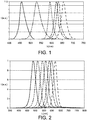
- Several approaches may be followed to create the desired spectral distributions. For instance, multiple LEDs with varying emission bands may be used, see Fig. 1 . Alternatively or additionally, conversion with multiple narrow-band phosphors may be used. The spectrum would then be composed of e.g. remaining excitation light (blue) if any/wanted and the converted light. Of course, one may prevent the issue of remaining blue by using UV-emitters only for creating white spectral distributions.
- narrow-band phosphors either organic phosphors or the (very narrow band) Quantum Dot phosphor types.
- emission spectra of a set of quantum dot phosphors of one type of composition and varying geometrical size is shown in Fig. 2 . Essentially, any emission maximum can be achieved by simply tuning the size of the quantum dot during fabrication.
- a highly tunable spectrum with multiple quantum dots based on multiple light sources in a luminaire, all these multiple light sources addressable and the light combined in a mixing luminaire.
- option two is herein selected as most obvious approach, and a hypothetic example is used to explain the approach that could be used in the light setting.
- Fig. 3a an example of a base setting is shown.
- the base line band left and right (here called blue-green base and red base) are activated, the four (this is a hypothetical number) interlaying phosphors (or NB LED emitters) are non-active.
- the blue-green and red base spectra might also be tuned in intensity, also being adapted while filling in the spectrum gap, as to create an 'as good as possible' overall white spectrum (for any user or observer). This could largely prevent the color spectrum from becoming 'pinkish' and therefor noticeable and possibly disturbing.
- the optimal illumination spectrum is formed by activating (for NB phosphors: switch on the (blue or UV) excitation source, for LED emitters: switch on the power) two of the four available interlaying colors, see Fig. 3b .
- another spectrum might be more optimal. This is depicted in the next graph, which suggests activating another selection of spectral lines, see Fig. 3c .
- the setting might be more optimal for a person that has a larger mismatch (unbalance in red and green sensitivity), so requiring a wider 'removal' of the overlapping wavelengths.
- the same effect might be created by changing the (relative) intensity of the spectral band peaks.
- the user may use a user interface as to allow him/her to change the light setting such that vision is improved.
- test visuals aka Ishihara Pseudo Isochromatic Plates
- settings might be selected with a single selection on an input device or via a smart phone that is connected to the connectivity enabled light source (and possibly already has the stored optimal setting for the user).
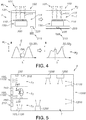
- Fig. 4 schematically depicts an embodiment of lighting system 1, with in the upper row a change from the first mode M1 to the second lighting mode M2, and with the lower row showing a possible impact on the spectral distribution of the lighting device light 101.
- the lighting system 10 comprises a lighting device 100 configured to provide lighting device light 101 with a variable spectral distribution SD, wherein the lighting system 1 comprises a control system 200 configured to control the spectral distribution SD of the lighting device light 101.
- the lighting device 1 comprises at least two lighting modes M1,M2.
- the lighting device 1 is configured to provide (white) visible light 101 with a first spectral distribution SD1 in the visible with a first spectral intensity P1 (in number of photons), the first spectral distribution SD1 having a spectral intensity gap G configured in the spectral range of 430-600 nm, the spectral intensity gap G having a spectral gap width GW1 of at least 20 nm and a maximum spectral gap intensity PG1 (in number of photons) of lighting device light 101 within the spectral intensity gap G of PG1/P1 ⁇ k, wherein k is a predefined intensity ratio value.
- the lighting device 1 is configured to provide white light 101 with a second spectral distribution SD2 with a second spectral intensity P2 (in number of photons), with a relatively enhanced intensity P2* (in number of photons) of the lighting device light 101 in the same spectral range (see dashed lines) of the spectral intensity gap G of the first lighting mode, wherein P2*/P2> k.
- the lighting device may comprise an adapted first lighting mode M1* alternative or additional to the first mode M1, wherein in response to one or more of the input signal of the user interface 210 or a sensor (see also below) at least part of the spectral intensity gap G is filled with light source light (111), thereby increasing k. Examples thereof are also shown in Figs. 3b and 3c .
- the lighting device light 101 may be composed of light source light 111 of a plurality of different light sources 110.
- the lighting system 1 may further comprise a controllable band filter 120 for reducing lighting device light 101 within the spectral range of the spectral intensity gap G.
- Fig. 5 schematically depicts an application of the lighting system 1, especially as retail lighting system 1000, wherein e.g. in specific space parts S1 of a space S lighting devices 100 may be configured for customized lighting.
- the lighting system 1 may further comprise a user interface 210 for instructing the control system 200, such as a touch screen, or a switch, or a slide switch, etc.
- the lighting system 1 may further comprising a communication element 220 for receiving instructions for the control system 200 from a wireless user interface 210, like an app.
- the lighting system 1 further comprises a receiver element 230 for receiving instructions (for the control system) from a wireless transmitter 240.
- the user in the middle space part S1 may carry a token, which, upon detection by the receiver element 230, instructs the control system to choose a specific spectral distribution, such as the first mode or a modified first mode.
- the retail lighting system 1000 may also include other lighting devices, indicated with reference 1200. Therefore, Fig. 5 schematically depicts an embodiment of 14.
- a retail lighting system 1000 comprising the lighting system 1 according to any one of the preceding claims, the retail lighting system 1000 comprising a plurality of system lighting devices 1100, wherein the system lighting devices 1100 comprise one or more lighting devices 100 and optionally one or more further lighting devices 1200, wherein each of the one or more lighting devices 100 comprise a basic mode BM, wherein the second lighting mode M2 is the default mode and wherein the one or more lighting devices 100 are configured to switch to the first mode M1 upon a signal received by the control system 200 and switch back to the second lighting mode M2 in response to one or more of a time signal, a sensor signal and a user interface instruction.
- Figs. 6a-6d schematically depict a non-limiting number of schemes, wherein switches to another mode may be triggered by a sensor signal, a user instruction, etc.
- BM indicates a basic mode
- M3 indicates another mode, e.g. non-white light.
- the lighting device may comprise one or more light sources.
- the lighting device may comprise a plurality of light sources.
- the term "light source” may refer to a semiconductor light-emitting device, such as a light emitting diode (LEDs), a resonant cavity light emitting diode (RCLED), a vertical cavity laser diode (VCSELs), an edge emitting laser, etc.
- the term "light source” may also refer to an organic light-emitting diode, such as a passive-matrix (PMOLED) or an active-matrix (AMOLED).
- the light source comprises a solid state light source (such as a LED or laser diode).
- the light source comprises a LED (light emitting diode).
- the term LED may also refer to a plurality of LEDs.
- the term “light source” may in embodiments also refer to a so-called chips-on-board (COB) light source.
- COB especially refers to LED chips in the form of a semiconductor chip that is neither encased nor connected but directly mounted onto a substrate, such as a PCB. Hence, a plurality of semiconductor light sources may be configured on the same substrate.
- a COB is a multi LED chip configured together as a single lighting module.
- the term "light source” may also relate to a plurality of light sources, such as 2-2000 solid state light sources.
- substantially herein, such as in “substantially all light” or in “substantially consists”, will be understood by the person skilled in the art.
- the term “substantially” may also include embodiments with “entirely”, “completely”, “all”, etc. Hence, in embodiments the adjective substantially may also be removed.
- the term “substantially” may also relate to 90% or higher, such as 95% or higher, especially 99% or higher, even more especially 99.5% or higher, including 100%.
- the term “comprise” includes also embodiments wherein the term “comprises” means “consists of'.
- the term “and/or” especially relates to one or more of the items mentioned before and after "and/or”.
- a phrase “item 1 and/or item 2" and similar phrases may relate to one or more of item 1 and item 2.
- the term “comprising” may in an embodiment refer to “consisting of' but may in another embodiment also refer to "containing at least the defined species and optionally one or more other species”.
Landscapes
- Engineering & Computer Science (AREA)
- General Engineering & Computer Science (AREA)
- Physics & Mathematics (AREA)
- Spectroscopy & Molecular Physics (AREA)
- Circuit Arrangement For Electric Light Sources In General (AREA)
Claims (15)
- Système d'éclairage (1) comprenant un dispositif d'éclairage (100) configuré pour fournir une lumière de dispositif d'éclairage (101) avec une distribution spectrale variable (SD), dans lequel le système d'éclairage (1) comprend un système de commande (200) configuré pour commander la distribution spectrale (SD) de la lumière de dispositif d'éclairage (101), dans lequel le dispositif d'éclairage (1) comprend au moins deux modes d'éclairage (M1, M2), dans lequel :(i) dans un premier mode d'éclairage (M1), le dispositif d'éclairage (1) est configuré pour fournir de la lumière blanche (101) avec une première distribution spectrale (SD1) dans le visible avec une première intensité spectrale P1, la première distribution spectrale (SD1) présentant une fente d'intensité spectrale (G) configurée dans une première plaque spectrale de 440 à 490 nm ou dans une seconde plage spectrale de 510 à 580 nm, la fente d'intensité spectrale (G) présentant une largeur de fente spectrale (GW1) d'au moins 40 nm et une intensité de fente spectrale maximum PG1 de lumière de dispositif d'éclairage (101) dans la fente d'intensité spectrale (G) de PG1/P1 ≤ 0,2, et(ii) dans un second mode d'éclairage (M2), le dispositif d'éclairage (1) est configuré pour fournir de la lumière blanche (101) avec une seconde distribution spectrale (SD2) avec une seconde intensité spectrale P2, avec une intensité relativement améliorée P2* de la lumière de dispositif d'éclairage (101) dans la même plage spectrale de la fente d'intensité spectrale (G) du premier mode d'éclairage, dans lequel P2*/P2>0,2, etle système d'éclairage (1) comprenant en outre une pluralité de sources de lumière (110) qui sont configurées pour fournir de la lumière de source de lumière (111) avec des longueurs d'onde seulement dans la fente d'intensité spectrale (G), dans lequel le système de commande (200) est configuré pour commander la pluralité de sources de lumière selon un ou plusieurs d'un signal d'entrée d'une interface utilisateur (210) et d'un capteur (250).
- Système d'éclairage (1) selon la revendication 1, dans lequel la largeur de fente spectrale (GW1) est d'au moins 50 nm.
- Système d'éclairage (1) selon l'une quelconque des revendications 1 à 2, dans lequel PG1/P1 est ≤ 0,1.
- Système d'éclairage (1) selon l'une quelconque des revendications précédentes 1 ou 3, dans lequel la largeur de fente spectrale (GW1) est dans la plage de 40 à 150 nm.
- Système d'éclairage (1) selon l'une quelconque des revendications précédentes, dans lequel la première plage spectrale ou la seconde plage spectrale est sélectionnée via l'interface utilisateur.
- Système d'éclairage (1) selon l'une quelconque des revendications précédentes, comprenant en outre un élément de communication (220) pour la réception d'instructions pour le système de commande (200) par l'interface utilisateur (210).
- Système d'éclairage (1) selon l'une quelconque des revendications précédentes, dans lequel la valeur de la largeur de fente spectrale (GW1) et/ou le rapport de l'intensité de fente spectrale PG1 de lumière de dispositif d'éclairage (101) dans la fente d'intensité spectrale (G) de PG1/1 est sélectionné(e) via l'interface utilisateur.
- Système d'éclairage (1) selon la revendication 7, dans lequel le dispositif d'éclairage (1) comprend aussi un premier mode d'éclairage adapté (M1*), dans lequel en réponse à un ou plusieurs du signal d'entrée de l'interface utilisateur (210) ou du capteur (250) au moins une partie de la fente d'intensité spectrale (G) est remplie avec une lumière de source de lumière (111), augmentant ainsi le PG1/PG.
- Système d'éclairage (1) selon l'une quelconque des revendications précédentes, comprenant une pluralité de sources de lumière (110), dans lequel deux ou plus sous-ensembles (115) de chaque une ou plusieurs sources de lumière (110) sont configurés pour fournir de la lumière de source de lumière (111) avec différentes distributions spectrales, et dans lequel le système de commande (200) est configuré pour commander la pluralité de sources de lumière (110) pour la fourniture de la lumière de dispositif d'éclairage (101) dans le premier mode d'éclairage (M1), ou le second mode d'éclairage (M2), ou un premier mode d'éclairage modifié (M1*) selon la revendication 8.
- Système d'éclairage (1) selon la revendication 9, dans lequel la pluralité de sources de lumière (110) comprend des émetteurs de bande, chacun étant configuré pour fournir de la lumière de source de lumière (111) présentant une moitié de largeur pleine maximum sélectionnée dans la plage de 10 à 150 nm.
- Système d'éclairage (1) selon l'une quelconque des revendications précédentes, dans lequel le système d'éclairage (1) comprend un mode de base (BM), dans lequel le second mode d'éclairage (M2) est le mode par défaut et dans lequel le dispositif d'éclairage (100) est configuré pour commuter dans le premier mode (M1) suite à un signal reçu par le système de commande (200) et recommuter dans le second mode d'éclairage (M2) en réponse à un ou plusieurs d'un signal de temps, un signal de capteur, et une instruction d'interface utilisateur.
- Système d'éclairage (1) selon l'une quelconque des revendications précédentes, dans lequel une position de la fente d'intensité spectrale (G) à l'intérieur dans la première plage spectrale de 440 à 490 nm ou dans une seconde plage spectrale de 510 à 580 nm est commandable.
- Système d'éclairage (1) selon l'une quelconque des revendications précédentes, comprenant en outre un filtre de bande commandable (120) pour la réduction de lumière de dispositif d'éclairage (101) dans la plage spectrale de la fente d'intensité spectrale (G).
- Système d'éclairage de détail (1000) comprenant le système d'éclairage (1) selon l'une quelconque des revendications précédentes, le système d'éclairage de détail (1000) comprenant une pluralité de dispositifs d'éclairage de système (1100), dans lequel les dispositifs d'éclairage de système (1100) comprennent un ou plusieurs dispositifs d'éclairage (100) et en option un ou plusieurs autres dispositifs d'éclairage (1200), dans lequel chacun des uns ou plusieurs dispositifs d'éclairage (100) comprend un mode de base (BM), dans lequel le second mode d'éclairage (M2) est le mode par défaut et dans lequel les un ou plusieurs dispositifs d'éclairage (100) sont configurés pour commuter dans le premier mode (M1) suite à un signal reçu par le système de commande (200) et recommuter dans le second mode d'éclairage (M2) en réponse à un ou plusieurs d'un signal de temps, un signal de capteur, et une instruction d'interface utilisateur.
- Système d'éclairage de détail (1000) selon la revendication 14, configuré pour recevoir des instructions d'une interface utilisateur distante.
Applications Claiming Priority (2)
| Application Number | Priority Date | Filing Date | Title |
|---|---|---|---|
| EP17163356 | 2017-03-28 | ||
| PCT/EP2018/057485 WO2018177944A1 (fr) | 2017-03-28 | 2018-03-23 | Source de lumière et procédé pour augmenter la perception des couleurs chez les personnes souffrant d'une vision défectueuse des couleurs |
Publications (2)
| Publication Number | Publication Date |
|---|---|
| EP3601874A1 EP3601874A1 (fr) | 2020-02-05 |
| EP3601874B1 true EP3601874B1 (fr) | 2020-06-17 |
Family
ID=58664439
Family Applications (1)
| Application Number | Title | Priority Date | Filing Date |
|---|---|---|---|
| EP18717247.3A Active EP3601874B1 (fr) | 2017-03-28 | 2018-03-23 | Source de lumière pour augmenter la perception des couleurs chez les personnes souffrant d'une vision défectueuse des couleurs |
Country Status (5)
| Country | Link |
|---|---|
| US (1) | US11246197B2 (fr) |
| EP (1) | EP3601874B1 (fr) |
| JP (1) | JP6818159B2 (fr) |
| CN (1) | CN110462281B (fr) |
| WO (1) | WO2018177944A1 (fr) |
Families Citing this family (2)
| Publication number | Priority date | Publication date | Assignee | Title |
|---|---|---|---|---|
| ES3062138T3 (en) * | 2020-11-20 | 2026-04-08 | Signify Holding Bv | Lighting system calibration |
| DE102021103698A1 (de) * | 2021-02-17 | 2022-08-18 | Ledvance Gmbh | Leuchtvorrichtung zum Erzeugen eines weißen Mischlichts mit steuerbaren Spektraleigenschaften |
Family Cites Families (24)
| Publication number | Priority date | Publication date | Assignee | Title |
|---|---|---|---|---|
| US6153971A (en) * | 1995-09-21 | 2000-11-28 | Matsushita Electric Industrial Co., Ltd. | Light source with only two major light emitting bands |
| US6414426B1 (en) | 1997-02-13 | 2002-07-02 | Matsushita Electric Industrial Co., Ltd. | High-efficiency light source |
| US20050104040A1 (en) | 2003-11-14 | 2005-05-19 | Mendelsohn Fred M. | Phosphors formulation for fluorescent lamps |
| JP2008047465A (ja) * | 2006-08-18 | 2008-02-28 | Seiwa Electric Mfg Co Ltd | 色覚障害者用照明装置 |
| US8203260B2 (en) | 2007-04-13 | 2012-06-19 | Intematix Corporation | Color temperature tunable white light source |
| JP2009158823A (ja) * | 2007-12-27 | 2009-07-16 | Sharp Corp | 照明装置 |
| BR112012032027A2 (pt) | 2010-06-17 | 2016-11-08 | Koninkl Philips Electronics Nv | disposição de visor e iluminação, espaço, dispositivo de iluminação para uso em uma disposição de visor e iluminação e método de controle da luz fornecida a uma pessoa em pose |
| JP2012028270A (ja) * | 2010-07-27 | 2012-02-09 | Panasonic Electric Works Co Ltd | 色覚障害者用照明システム |
| JP5996563B2 (ja) | 2011-03-03 | 2016-09-21 | エンクロマ, インコーポレイテッド | 多帯域色視フィルタおよびlp最適化による方法 |
| DK2982224T3 (en) * | 2013-04-04 | 2019-01-21 | Circadian Zirclight Inc | LIGHTING SYSTEMS TO PROTECT CIRCADIC NEUROENDOCRINE FUNCTION |
| WO2014166930A1 (fr) * | 2013-04-09 | 2014-10-16 | Koninklijke Philips N.V. | Agencement pour changer l'aspect visuel d'un objet cible |
| JP5593417B1 (ja) * | 2013-04-30 | 2014-09-24 | 株式会社サンステート | 色覚異常者用照明装置 |
| US9557016B2 (en) * | 2013-08-02 | 2017-01-31 | Philips Lighting Holding B.V. | Color rendering index tunable lamp and luminaire |
| MX362658B (es) | 2013-09-09 | 2019-01-30 | Ge Lighting Solutions Llc | Fuentes de luz de preferencia de color mejorado. |
| CN113209490A (zh) * | 2013-10-09 | 2021-08-06 | 昕诺飞控股有限公司 | 具有逼近白光的cri的无褪黑素抑制光源 |
| US10288233B2 (en) * | 2013-12-10 | 2019-05-14 | Gary W. Jones | Inverse visible spectrum light and broad spectrum light source for enhanced vision |
| US9551468B2 (en) * | 2013-12-10 | 2017-01-24 | Gary W. Jones | Inverse visible spectrum light and broad spectrum light source for enhanced vision |
| NL2012028C2 (en) * | 2013-12-24 | 2015-06-26 | Gemex Consultancy B V | Spectral equalizer. |
| US10089900B2 (en) | 2014-05-30 | 2018-10-02 | Wolfcub Vision, Inc. | Systems and methods for expanding human perception |
| JP6696912B2 (ja) * | 2014-06-05 | 2020-05-20 | ウニベルジテート ハイデルベルク | マルチスペクトルイメージングのための方法及び手段 |
| WO2016146688A1 (fr) | 2015-03-19 | 2016-09-22 | Philips Lighting Holding B.V. | Lampe bio à nuances |
| JP6866306B2 (ja) * | 2015-05-26 | 2021-05-12 | シグニファイ ホールディング ビー ヴィSignify Holding B.V. | スイッチング可能な高カラーコントラストライティング |
| KR20170001408A (ko) * | 2015-06-26 | 2017-01-04 | 한국광기술원 | 색각 이상용 조명모듈을 이용한 조명장치 |
| JP6875377B2 (ja) * | 2015-09-01 | 2021-05-26 | シグニファイ ホールディング ビー ヴィSignify Holding B.V. | 効率及び赤色過飽和度が向上された食肉照明システム |
-
2018
- 2018-03-23 EP EP18717247.3A patent/EP3601874B1/fr active Active
- 2018-03-23 JP JP2019553057A patent/JP6818159B2/ja active Active
- 2018-03-23 US US16/496,990 patent/US11246197B2/en active Active
- 2018-03-23 CN CN201880022580.0A patent/CN110462281B/zh active Active
- 2018-03-23 WO PCT/EP2018/057485 patent/WO2018177944A1/fr not_active Ceased
Non-Patent Citations (1)
| Title |
|---|
| None * |
Also Published As
| Publication number | Publication date |
|---|---|
| EP3601874A1 (fr) | 2020-02-05 |
| WO2018177944A1 (fr) | 2018-10-04 |
| JP2020512667A (ja) | 2020-04-23 |
| CN110462281B (zh) | 2021-06-04 |
| CN110462281A (zh) | 2019-11-15 |
| JP6818159B2 (ja) | 2021-01-20 |
| US20210329754A1 (en) | 2021-10-21 |
| US11246197B2 (en) | 2022-02-08 |
Similar Documents
| Publication | Publication Date | Title |
|---|---|---|
| EP2528481B1 (fr) | Procédé et système pour mettre en valeur la couleur d'un objet | |
| JP7383373B2 (ja) | 低青色光ディスプレイ | |
| US9635730B2 (en) | Color emphasis and preservation of objects using reflection spectra | |
| CN115362760B (zh) | 使用青色泵浦白色led的黑视光系统 | |
| KR102516217B1 (ko) | 발광 다이오드들을 포함하는 발광 장치 | |
| JP2005259699A (ja) | Ledを利用して白色光を生じるシステム及びその動作方法 | |
| CN103299718A (zh) | 照明方法和发光装置 | |
| CN115606321B (zh) | 具有高cri的使用青色直接发射器的黑视光系统 | |
| WO2007105134A1 (fr) | Dispositif de commande pour commander la couleur de la lumière émise à partir d'une source lumineuse | |
| US11246197B2 (en) | Light source and method for augmenting color perception for color deficient persons | |
| US11076461B2 (en) | User control modality for LED color tuning | |
| WO2020226970A1 (fr) | Sélection de paramètres dans une application d'ajustement de couleur | |
| TWI836076B (zh) | 發光二極體色彩調諧之使用者控制模態 | |
| US20040212546A1 (en) | Perception-based management of color in display systems | |
| KR101279342B1 (ko) | 컬러 디스플레이 디바이스와 그 동작 방법 | |
| CN104737473A (zh) | 用于光编码的方法、光模块和接收单元 | |
| US10699606B2 (en) | Method and apparatus using a combination of quantum dot-containing films with optical filter films for signage and illumination applications | |
| CN110235523B (zh) | 用于区分黑色阴影的深黑照明设备 | |
| JP7669133B2 (ja) | 表示装置および機器 | |
| US9674920B2 (en) | Illumination system and method for developing target visual perception of an object | |
| JP2016057583A (ja) | 表示装置及びその制御方法 | |
| WO2021105029A1 (fr) | Dispositif d'éclairage à papillotement de dispositif proche du métamère | |
| EP3811736A1 (fr) | Sytème d'éclairage doté d'un capteur intégré | |
| KR20170068745A (ko) | 색온도 가변형 cob 모듈 | |
| JP2005284977A (ja) | 道路情報表示装置、道路情報表示方法および表示色変換ユニット |
Legal Events
| Date | Code | Title | Description |
|---|---|---|---|
| STAA | Information on the status of an ep patent application or granted ep patent |
Free format text: STATUS: UNKNOWN |
|
| STAA | Information on the status of an ep patent application or granted ep patent |
Free format text: STATUS: THE INTERNATIONAL PUBLICATION HAS BEEN MADE |
|
| PUAI | Public reference made under article 153(3) epc to a published international application that has entered the european phase |
Free format text: ORIGINAL CODE: 0009012 |
|
| STAA | Information on the status of an ep patent application or granted ep patent |
Free format text: STATUS: REQUEST FOR EXAMINATION WAS MADE |
|
| GRAP | Despatch of communication of intention to grant a patent |
Free format text: ORIGINAL CODE: EPIDOSNIGR1 |
|
| STAA | Information on the status of an ep patent application or granted ep patent |
Free format text: STATUS: GRANT OF PATENT IS INTENDED |
|
| REG | Reference to a national code |
Ref country code: DE Ref legal event code: R079 Ref document number: 602018005413 Country of ref document: DE Free format text: PREVIOUS MAIN CLASS: F21S0010020000 Ipc: F21V0023040000 |
|
| 17P | Request for examination filed |
Effective date: 20191028 |
|
| AK | Designated contracting states |
Kind code of ref document: A1 Designated state(s): AL AT BE BG CH CY CZ DE DK EE ES FI FR GB GR HR HU IE IS IT LI LT LU LV MC MK MT NL NO PL PT RO RS SE SI SK SM TR |
|
| AX | Request for extension of the european patent |
Extension state: BA ME |
|
| INTG | Intention to grant announced |
Effective date: 20200115 |
|
| RIC1 | Information provided on ipc code assigned before grant |
Ipc: H05B 45/20 20200101ALI20200122BHEP Ipc: F21V 23/04 20060101AFI20200122BHEP |
|
| GRAS | Grant fee paid |
Free format text: ORIGINAL CODE: EPIDOSNIGR3 |
|
| GRAA | (expected) grant |
Free format text: ORIGINAL CODE: 0009210 |
|
| STAA | Information on the status of an ep patent application or granted ep patent |
Free format text: STATUS: THE PATENT HAS BEEN GRANTED |
|
| AK | Designated contracting states |
Kind code of ref document: B1 Designated state(s): AL AT BE BG CH CY CZ DE DK EE ES FI FR GB GR HR HU IE IS IT LI LT LU LV MC MK MT NL NO PL PT RO RS SE SI SK SM TR |
|
| DAV | Request for validation of the european patent (deleted) | ||
| DAX | Request for extension of the european patent (deleted) | ||
| REG | Reference to a national code |
Ref country code: GB Ref legal event code: FG4D |
|
| REG | Reference to a national code |
Ref country code: CH Ref legal event code: EP |
|
| REG | Reference to a national code |
Ref country code: IE Ref legal event code: FG4D |
|
| REG | Reference to a national code |
Ref country code: DE Ref legal event code: R096 Ref document number: 602018005413 Country of ref document: DE |
|
| REG | Reference to a national code |
Ref country code: AT Ref legal event code: REF Ref document number: 1281758 Country of ref document: AT Kind code of ref document: T Effective date: 20200715 |
|
| PG25 | Lapsed in a contracting state [announced via postgrant information from national office to epo] |
Ref country code: NO Free format text: LAPSE BECAUSE OF FAILURE TO SUBMIT A TRANSLATION OF THE DESCRIPTION OR TO PAY THE FEE WITHIN THE PRESCRIBED TIME-LIMIT Effective date: 20200917 Ref country code: LT Free format text: LAPSE BECAUSE OF FAILURE TO SUBMIT A TRANSLATION OF THE DESCRIPTION OR TO PAY THE FEE WITHIN THE PRESCRIBED TIME-LIMIT Effective date: 20200617 Ref country code: FI Free format text: LAPSE BECAUSE OF FAILURE TO SUBMIT A TRANSLATION OF THE DESCRIPTION OR TO PAY THE FEE WITHIN THE PRESCRIBED TIME-LIMIT Effective date: 20200617 Ref country code: SE Free format text: LAPSE BECAUSE OF FAILURE TO SUBMIT A TRANSLATION OF THE DESCRIPTION OR TO PAY THE FEE WITHIN THE PRESCRIBED TIME-LIMIT Effective date: 20200617 Ref country code: GR Free format text: LAPSE BECAUSE OF FAILURE TO SUBMIT A TRANSLATION OF THE DESCRIPTION OR TO PAY THE FEE WITHIN THE PRESCRIBED TIME-LIMIT Effective date: 20200918 |
|
| REG | Reference to a national code |
Ref country code: LT Ref legal event code: MG4D |
|
| REG | Reference to a national code |
Ref country code: NL Ref legal event code: MP Effective date: 20200617 |
|
| PG25 | Lapsed in a contracting state [announced via postgrant information from national office to epo] |
Ref country code: BG Free format text: LAPSE BECAUSE OF FAILURE TO SUBMIT A TRANSLATION OF THE DESCRIPTION OR TO PAY THE FEE WITHIN THE PRESCRIBED TIME-LIMIT Effective date: 20200917 Ref country code: RS Free format text: LAPSE BECAUSE OF FAILURE TO SUBMIT A TRANSLATION OF THE DESCRIPTION OR TO PAY THE FEE WITHIN THE PRESCRIBED TIME-LIMIT Effective date: 20200617 Ref country code: LV Free format text: LAPSE BECAUSE OF FAILURE TO SUBMIT A TRANSLATION OF THE DESCRIPTION OR TO PAY THE FEE WITHIN THE PRESCRIBED TIME-LIMIT Effective date: 20200617 Ref country code: HR Free format text: LAPSE BECAUSE OF FAILURE TO SUBMIT A TRANSLATION OF THE DESCRIPTION OR TO PAY THE FEE WITHIN THE PRESCRIBED TIME-LIMIT Effective date: 20200617 |
|
| REG | Reference to a national code |
Ref country code: AT Ref legal event code: MK05 Ref document number: 1281758 Country of ref document: AT Kind code of ref document: T Effective date: 20200617 |
|
| PG25 | Lapsed in a contracting state [announced via postgrant information from national office to epo] |
Ref country code: AL Free format text: LAPSE BECAUSE OF FAILURE TO SUBMIT A TRANSLATION OF THE DESCRIPTION OR TO PAY THE FEE WITHIN THE PRESCRIBED TIME-LIMIT Effective date: 20200617 Ref country code: NL Free format text: LAPSE BECAUSE OF FAILURE TO SUBMIT A TRANSLATION OF THE DESCRIPTION OR TO PAY THE FEE WITHIN THE PRESCRIBED TIME-LIMIT Effective date: 20200617 |
|
| PG25 | Lapsed in a contracting state [announced via postgrant information from national office to epo] |
Ref country code: SM Free format text: LAPSE BECAUSE OF FAILURE TO SUBMIT A TRANSLATION OF THE DESCRIPTION OR TO PAY THE FEE WITHIN THE PRESCRIBED TIME-LIMIT Effective date: 20200617 Ref country code: IT Free format text: LAPSE BECAUSE OF FAILURE TO SUBMIT A TRANSLATION OF THE DESCRIPTION OR TO PAY THE FEE WITHIN THE PRESCRIBED TIME-LIMIT Effective date: 20200617 Ref country code: AT Free format text: LAPSE BECAUSE OF FAILURE TO SUBMIT A TRANSLATION OF THE DESCRIPTION OR TO PAY THE FEE WITHIN THE PRESCRIBED TIME-LIMIT Effective date: 20200617 Ref country code: CZ Free format text: LAPSE BECAUSE OF FAILURE TO SUBMIT A TRANSLATION OF THE DESCRIPTION OR TO PAY THE FEE WITHIN THE PRESCRIBED TIME-LIMIT Effective date: 20200617 Ref country code: RO Free format text: LAPSE BECAUSE OF FAILURE TO SUBMIT A TRANSLATION OF THE DESCRIPTION OR TO PAY THE FEE WITHIN THE PRESCRIBED TIME-LIMIT Effective date: 20200617 Ref country code: EE Free format text: LAPSE BECAUSE OF FAILURE TO SUBMIT A TRANSLATION OF THE DESCRIPTION OR TO PAY THE FEE WITHIN THE PRESCRIBED TIME-LIMIT Effective date: 20200617 Ref country code: PT Free format text: LAPSE BECAUSE OF FAILURE TO SUBMIT A TRANSLATION OF THE DESCRIPTION OR TO PAY THE FEE WITHIN THE PRESCRIBED TIME-LIMIT Effective date: 20201019 Ref country code: ES Free format text: LAPSE BECAUSE OF FAILURE TO SUBMIT A TRANSLATION OF THE DESCRIPTION OR TO PAY THE FEE WITHIN THE PRESCRIBED TIME-LIMIT Effective date: 20200617 |
|
| PG25 | Lapsed in a contracting state [announced via postgrant information from national office to epo] |
Ref country code: PL Free format text: LAPSE BECAUSE OF FAILURE TO SUBMIT A TRANSLATION OF THE DESCRIPTION OR TO PAY THE FEE WITHIN THE PRESCRIBED TIME-LIMIT Effective date: 20200617 Ref country code: SK Free format text: LAPSE BECAUSE OF FAILURE TO SUBMIT A TRANSLATION OF THE DESCRIPTION OR TO PAY THE FEE WITHIN THE PRESCRIBED TIME-LIMIT Effective date: 20200617 Ref country code: IS Free format text: LAPSE BECAUSE OF FAILURE TO SUBMIT A TRANSLATION OF THE DESCRIPTION OR TO PAY THE FEE WITHIN THE PRESCRIBED TIME-LIMIT Effective date: 20201017 |
|
| REG | Reference to a national code |
Ref country code: DE Ref legal event code: R097 Ref document number: 602018005413 Country of ref document: DE |
|
| PLBE | No opposition filed within time limit |
Free format text: ORIGINAL CODE: 0009261 |
|
| STAA | Information on the status of an ep patent application or granted ep patent |
Free format text: STATUS: NO OPPOSITION FILED WITHIN TIME LIMIT |
|
| PG25 | Lapsed in a contracting state [announced via postgrant information from national office to epo] |
Ref country code: DK Free format text: LAPSE BECAUSE OF FAILURE TO SUBMIT A TRANSLATION OF THE DESCRIPTION OR TO PAY THE FEE WITHIN THE PRESCRIBED TIME-LIMIT Effective date: 20200617 |
|
| 26N | No opposition filed |
Effective date: 20210318 |
|
| PG25 | Lapsed in a contracting state [announced via postgrant information from national office to epo] |
Ref country code: MC Free format text: LAPSE BECAUSE OF FAILURE TO SUBMIT A TRANSLATION OF THE DESCRIPTION OR TO PAY THE FEE WITHIN THE PRESCRIBED TIME-LIMIT Effective date: 20200617 |
|
| REG | Reference to a national code |
Ref country code: CH Ref legal event code: PL |
|
| REG | Reference to a national code |
Ref country code: BE Ref legal event code: MM Effective date: 20210331 |
|
| PG25 | Lapsed in a contracting state [announced via postgrant information from national office to epo] |
Ref country code: LU Free format text: LAPSE BECAUSE OF NON-PAYMENT OF DUE FEES Effective date: 20210323 Ref country code: LI Free format text: LAPSE BECAUSE OF NON-PAYMENT OF DUE FEES Effective date: 20210331 Ref country code: IE Free format text: LAPSE BECAUSE OF NON-PAYMENT OF DUE FEES Effective date: 20210323 Ref country code: CH Free format text: LAPSE BECAUSE OF NON-PAYMENT OF DUE FEES Effective date: 20210331 |
|
| PG25 | Lapsed in a contracting state [announced via postgrant information from national office to epo] |
Ref country code: BE Free format text: LAPSE BECAUSE OF NON-PAYMENT OF DUE FEES Effective date: 20210331 |
|
| P01 | Opt-out of the competence of the unified patent court (upc) registered |
Effective date: 20230425 |
|
| PG25 | Lapsed in a contracting state [announced via postgrant information from national office to epo] |
Ref country code: CY Free format text: LAPSE BECAUSE OF FAILURE TO SUBMIT A TRANSLATION OF THE DESCRIPTION OR TO PAY THE FEE WITHIN THE PRESCRIBED TIME-LIMIT Effective date: 20200617 |
|
| PG25 | Lapsed in a contracting state [announced via postgrant information from national office to epo] |
Ref country code: HU Free format text: LAPSE BECAUSE OF FAILURE TO SUBMIT A TRANSLATION OF THE DESCRIPTION OR TO PAY THE FEE WITHIN THE PRESCRIBED TIME-LIMIT; INVALID AB INITIO Effective date: 20180323 |
|
| PG25 | Lapsed in a contracting state [announced via postgrant information from national office to epo] |
Ref country code: SI Free format text: LAPSE BECAUSE OF FAILURE TO SUBMIT A TRANSLATION OF THE DESCRIPTION OR TO PAY THE FEE WITHIN THE PRESCRIBED TIME-LIMIT Effective date: 20200617 |
|
| PG25 | Lapsed in a contracting state [announced via postgrant information from national office to epo] |
Ref country code: MK Free format text: LAPSE BECAUSE OF FAILURE TO SUBMIT A TRANSLATION OF THE DESCRIPTION OR TO PAY THE FEE WITHIN THE PRESCRIBED TIME-LIMIT Effective date: 20200617 |
|
| PG25 | Lapsed in a contracting state [announced via postgrant information from national office to epo] |
Ref country code: MT Free format text: LAPSE BECAUSE OF FAILURE TO SUBMIT A TRANSLATION OF THE DESCRIPTION OR TO PAY THE FEE WITHIN THE PRESCRIBED TIME-LIMIT Effective date: 20200617 |
|
| PG25 | Lapsed in a contracting state [announced via postgrant information from national office to epo] |
Ref country code: TR Free format text: LAPSE BECAUSE OF FAILURE TO SUBMIT A TRANSLATION OF THE DESCRIPTION OR TO PAY THE FEE WITHIN THE PRESCRIBED TIME-LIMIT Effective date: 20200617 |
|
| PGFP | Annual fee paid to national office [announced via postgrant information from national office to epo] |
Ref country code: GB Payment date: 20260319 Year of fee payment: 9 |
|
| PGFP | Annual fee paid to national office [announced via postgrant information from national office to epo] |
Ref country code: FR Payment date: 20260323 Year of fee payment: 9 |
|
| PGFP | Annual fee paid to national office [announced via postgrant information from national office to epo] |
Ref country code: DE Payment date: 20260522 Year of fee payment: 9 |