EP3601905B1 - Réfrigérateur optique et capteur comportant un tel réfrigérateur - Google Patents
Réfrigérateur optique et capteur comportant un tel réfrigérateur Download PDFInfo
- Publication number
- EP3601905B1 EP3601905B1 EP18714580.0A EP18714580A EP3601905B1 EP 3601905 B1 EP3601905 B1 EP 3601905B1 EP 18714580 A EP18714580 A EP 18714580A EP 3601905 B1 EP3601905 B1 EP 3601905B1
- Authority
- EP
- European Patent Office
- Prior art keywords
- crystal
- cooled
- refrigerator
- plates
- refrigerator according
- Prior art date
- Legal status (The legal status is an assumption and is not a legal conclusion. Google has not performed a legal analysis and makes no representation as to the accuracy of the status listed.)
- Active
Links
Images

Classifications
-
- F—MECHANICAL ENGINEERING; LIGHTING; HEATING; WEAPONS; BLASTING
- F25—REFRIGERATION OR COOLING; COMBINED HEATING AND REFRIGERATION SYSTEMS; HEAT PUMP SYSTEMS; MANUFACTURE OR STORAGE OF ICE; LIQUEFACTION SOLIDIFICATION OF GASES
- F25B—REFRIGERATION MACHINES, PLANTS OR SYSTEMS; COMBINED HEATING AND REFRIGERATION SYSTEMS; HEAT PUMP SYSTEMS
- F25B23/00—Machines, plants or systems, with a single mode of operation not covered by groups F25B1/00 - F25B21/00, e.g. using selective radiation effect
- F25B23/003—Machines, plants or systems, with a single mode of operation not covered by groups F25B1/00 - F25B21/00, e.g. using selective radiation effect using selective radiation effect
-
- F—MECHANICAL ENGINEERING; LIGHTING; HEATING; WEAPONS; BLASTING
- F25—REFRIGERATION OR COOLING; COMBINED HEATING AND REFRIGERATION SYSTEMS; HEAT PUMP SYSTEMS; MANUFACTURE OR STORAGE OF ICE; LIQUEFACTION SOLIDIFICATION OF GASES
- F25B—REFRIGERATION MACHINES, PLANTS OR SYSTEMS; COMBINED HEATING AND REFRIGERATION SYSTEMS; HEAT PUMP SYSTEMS
- F25B23/00—Machines, plants or systems, with a single mode of operation not covered by groups F25B1/00 - F25B21/00, e.g. using selective radiation effect
-
- G—PHYSICS
- G01—MEASURING; TESTING
- G01J—MEASUREMENT OF INTENSITY, VELOCITY, SPECTRAL CONTENT, POLARISATION, PHASE OR PULSE CHARACTERISTICS OF INFRARED, VISIBLE OR ULTRAVIOLET LIGHT; COLORIMETRY; RADIATION PYROMETRY
- G01J1/00—Photometry, e.g. photographic exposure meter
- G01J1/02—Details
- G01J1/0252—Constructional arrangements for compensating for fluctuations caused by, e.g. temperature, or using cooling or temperature stabilization of parts of the device; Controlling the atmosphere inside a photometer; Purge systems, cleaning devices
-
- H—ELECTRICITY
- H01—ELECTRIC ELEMENTS
- H01S—DEVICES USING THE PROCESS OF LIGHT AMPLIFICATION BY STIMULATED EMISSION OF RADIATION [LASER] TO AMPLIFY OR GENERATE LIGHT; DEVICES USING STIMULATED EMISSION OF ELECTROMAGNETIC RADIATION IN WAVE RANGES OTHER THAN OPTICAL
- H01S3/00—Lasers, i.e. devices using stimulated emission of electromagnetic radiation in the infrared, visible or ultraviolet wave range
- H01S3/02—Constructional details
- H01S3/04—Arrangements for thermal management
- H01S3/042—Arrangements for thermal management for solid state lasers
Definitions
- the invention relates to an optical refrigerator as well as a detector comprising a refrigerator.
- the invention relates more particularly to an optical refrigerator, in particular for cooling an infrared sensor or detector, the refrigerator comprising a source of laser radiation, a cooling crystal configured to receive the laser radiation from the source and to cool itself, an element to be cooled and a thermal bond in thermal exchange on the one hand with the crystal and, on the other hand with the element to be cooled, to transfer frigories from the crystal to the element to be cooled.
- a known optical cooling method is based on anti-stokes or “anti-stokes fluorescence” displacement. See for example US9362712 , US60441610 or US8720219 .
- This solution is based on the following physical principle: when the emission and absorption bands of a material (crystal) are superimposed, the excitation of the upper part of the absorption spectrum leads to the emission of more energetic photons than the absorbed photons. This difference in energy (emission / absorption) is due to the annihilation of phonons in the crystal lattice of the material, the vibratory quanta for solids. In the solid state, thermal energy is mainly contained in the vibratory modes of the network.
- This refrigeration technology is potentially applicable to the cooling of sensors in the space field.
- the thermal bond consists of a trunk of material (generally sapphire) in the shape of a J, the end faces (end sections) of which are in contact respectively with the crystal and with the element to be cooled.
- the J or angled shape is designed to offset the crystal from the axis of the plane of the element to be cooled while minimizing the transmitted radiation (cf.
- US2015075181A1 discloses an optical refrigerator according to the preamble of claim 1.
- An object of the present invention is to overcome all or part of the drawbacks of the prior art noted above.
- the refrigerator according to the invention is essentially characterized in that the thermal link comprises two blades having respective first ends in thermal exchange respectively with two distinct surfaces of the crystal, the two plates having second ends in thermal exchange with the element to be cooled.
- the refrigerator according to the invention is defined in claim 1.
- This structure of the refrigerator makes it possible in particular to ensure better mechanical strength of the crystal via the thermal bond.
- This structure of the link in at least two parts (two blades) also ensures a mechanical redundancy of the cold maintenance and transfer function which is essential for the reliability of a space application.
- the anti-stoke radiation is guided less towards the element to be cooled and the heat exchange surfaces with the crystal and the element to be cooled can be increased.
- the invention also relates to a detector comprising a measuring member and a refrigerator of the measuring member, the refrigerator complying with any one of the characteristics above or below.
- the invention may also relate to any alternative device or method comprising any combination of the characteristics above or below.
- the figure 1 illustrates the structure and principle of operation of an optical refrigerator.
- Such a refrigerator 1 comprises a source 2 of laser radiation configured to emit radiation towards a cooling crystal 3 (cf. figure 5 also).
- Crystal 3 is flanked between at least two reflecting mirrors 7 in order to concentrate the light in crystal 3.
- the assembly (and in particular type of crystal 3 or equivalent) is configured to generate cooling of crystal 3 by the "Anti-Stokes" effect. ".
- the crystal 3 is placed in thermal exchange (contact) with an element 4, 5 to be cooled via a thermal link 6.
- the thermal link comprises two blades 6 having respective first ends in thermal exchange (preferably direct contact) respectively with two distinct surfaces of the crystal 3, the two plates 6 having second ends in heat exchange (preferably direct contact) with the element 4 to be cooled.
- the second ends of the two blades 6 are preferably in heat exchange respectively with two separate surfaces or sides of the element 4 to be cooled.
- the second ends of the two blades 6 sandwich (enclose laterally) the element 4 to be cooled, that is to say that the blades 6 are arranged on either side of two opposite sides of the element 4 to be cooled (cf. figure 2 to 6 ).
- the first ends of the two blades 6 preferably sandwich the crystal 3, that is to say that the blades 6 are arranged on either side of two opposite sides of the crystal 3.
- the blades 6 preferably each have a bent or "J" shape, that is to say that each blade 6 extends in a plane non-rectilinearly, the ends of the blade 6 in heat exchange respectively with the crystal 3 and the element 4 to be cooled being situated respectively at the level of two ends situated on either side of the bend or angle.
- the blades 6 have for example a thickness between 0.5 and 5mm, a width between 1 and 10mm and a length between 2 and 40mm. At each end the blades 6 are in contact with the crystal 3 and the element to cool on a surface for example comprised 1mm 2 and 75mm 2 and 1mm 2 and 100mm 2 respectively.
- the contact surfaces for heat exchange are thus significantly increased compared to known solutions without increasing the size of the device.
- the two blades 6 are made, for example, of sapphire or any other or other suitable transparent material: glass, etc.
- transparent is meant in particular: transparent at the appropriate wavelengths (for example to allow the radiation emitted by the crystal to pass through which is symbolized by lines or arrows in the figures).
- This geometry makes it possible to limit the amount of anti-stoke radiation from the crystal towards the element 4 to be cooled.
- this architecture of thin blades 6 makes it possible to easily arrange around the crystal 3 the mirrors 7 and optical screens 8.
- the optical screens 8 (sometimes called “optical baffles”) are provided to isolate the crystal and in particular to absorb radiation. around the crystal 3.
- These screens 8 can be composed in particular of metallic material, copper, aluminum, etc.
- optical screens 8 can be placed on either side of the first ends of the blades 6 in contact with the crystal 3.
- the thermal link architecture 6 makes it possible to arrange the screens 8 optical all around the crystal 3.
- a screen 8 can be placed opposite the six faces of the crystal 3.
- the laser source 2 can be configured to direct a beam through an orifice of a screen 8.
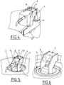
- the figures 4 to 6 illustrate an example of the structure of an integrated assembly comprising a cooler 1 and a detector (in particular infrared).
- the volume of the refrigerator part can be reduced, for example, to a cubic volume of less than ten cm per side.
- the detection plate can be simplified.
- the thermal link is in exchange with a part 4 which can be a focal plane in thermal exchange with a component 5 of the sensor to be cooled, such as an optical sensor of a space device (satellite or other).
- This architecture also presents an increased thermal response speed. In fact, it seems possible to achieve a cooling down time to the target temperature (without load) of the order of approximately 10 minutes.
- the invention can also be applied to the in-situ cooling of microelectronic components (for example microcircuits or power transistors) at temperatures close to the ambient, and the cooling of crystals used in high power lasers (continuous or pulsed. ).
- microelectronic components for example microcircuits or power transistors
- crystals used in high power lasers continuously or pulsed.
Landscapes
- Physics & Mathematics (AREA)
- Engineering & Computer Science (AREA)
- Electromagnetism (AREA)
- Mechanical Engineering (AREA)
- Thermal Sciences (AREA)
- General Engineering & Computer Science (AREA)
- Spectroscopy & Molecular Physics (AREA)
- General Physics & Mathematics (AREA)
- Health & Medical Sciences (AREA)
- Toxicology (AREA)
- Optics & Photonics (AREA)
- Plasma & Fusion (AREA)
- Devices That Are Associated With Refrigeration Equipment (AREA)
- Lasers (AREA)
- Photometry And Measurement Of Optical Pulse Characteristics (AREA)
- Radiation Pyrometers (AREA)
- Optical Modulation, Optical Deflection, Nonlinear Optics, Optical Demodulation, Optical Logic Elements (AREA)
- Optical Elements Other Than Lenses (AREA)
Description
- L'invention concerne un réfrigérateur optique ainsi qu'un détecteur comprenant un réfrigérateur.
- L'invention concerne plus particulièrement un réfrigérateur optique, notamment pour le refroidissement d'un capteur ou détecteur infrarouge, le réfrigérateur comprenant une source de rayonnement laser, un cristal de refroidissement configuré pour recevoir le rayonnement laser de la source et se refroidir, un élément à refroidir et un lien thermique en échange thermique d'une part avec le cristal et, d'autre part avec l'élément à refroidir, pour transférer des frigories du cristal vers l'élément à refroidir.
- Pour l'observation de la terre par satellite dans le domaine de l'infrarouge, il est nécessaire de refroidir les détecteurs ou photo-détecteurs infrarouge à des températures cryogéniques, typiquement inférieures à 200 K. Les solutions actuelles reposent soit sur l'utilisation de systèmes passifs, soit des systèmes actifs à base d'actionneurs mécaniques.
- Une méthode de refroidissement optique connue repose sur le déplacement anti-stokes ou « fluorescence anti-stokes ». Cf. par exemple
US9362712 US60441610 US8720219 . Cette solution repose sur le principe physique suivant : lorsque les bandes d'émission et absorption d'un matériau (cristal) sont superposées, l'excitation de la partie supérieure du spectre d'absorption conduit à l'émission de photons plus énergétiques que les photons absorbés. Cette différence d'énergie (émission/absorption) est due à l'annihilation de phonons dans le réseau cristallin du matériau, le quanta vibratoire pour les solides. A l'état solide, l'énergie thermique est principalement contenue dans les modes vibratoires du réseau. En effet l'agitation thermique provoque l'oscillation des atomes autour de leur position d'équilibre. En conséquence la chaleur est extraite du matériau par l'émission anti-stokes ce qui induit un effet de refroidissement. Cf. également la publication de M.Sheik-Bahe and R.I. Epstein « Optical Réfrigération » Nat. Photonics 1, 12, 693 (2007). - Cette technologie de réfrigération est potentiellement applicable au refroidissement de capteurs dans le domaine spatial.
- Dans les solutions connues, le lien thermique est constitué d'un tronc de matière (saphir en général) en forme de J dont les faces d'extrémités (sections terminales) sont en contact respectivement avec le cristal et avec l'élément à refroidir. La forme en J ou coudée est prévue pour déporter le cristal de l'axe du plan de l'élément à refroidir tout en minimisant le rayonnement transmis (cf.
-
US2015075181A1 ).US 2015075181 A1 divulgue un réfrigérateur optique selon le préambule de la revendication 1. - Les dispositifs connus sont cependant peu compatibles avec les contraintes de certaines applications, notamment spatiales.
- Ces contraintes ou insuffisances de l'art antérieur peuvent concerner en particulier tout ou partie de :
- la tenue mécanique du cristal sur l'élément à refroidir,
- la conduction de l'énergie à extraire de l'élément à refroidir vers le cristal,
- la limitation des pertes thermiques (le lien thermique doit piéger le minimum de rayonnement anti-Stokes ou transférer le minimum de ce rayonnement vers l'élément à refroidir),
- le problème de fiabilité en cas de casse d'un élément du dispositif.
- Un but de la présente invention est de pallier tout ou partie des inconvénients de l'art antérieur relevés ci-dessus.
- A cette fin, le réfrigérateur selon l'invention, par ailleurs conforme à la définition générique qu'en donne le préambule ci-dessus, est essentiellement caractérisé en ce que le lien thermique comprend deux lames ayant de premières extrémités respectives en échange thermique respectivement avec deux surfaces distinctes du cristal les deux lames ayant de secondes extrémités en échange thermique avec l'élément à refroidir. Le réfrigérateur selon l'invention est défini dans la revendication 1.
- Cette structure du réfrigérateur permet en particulier d'assurer une meilleure tenue mécanique du cristal via le lien thermique. Cette structure du lien en deux parties au moins (deux lames) assure également une redondance mécanique de la fonction de maintien et de transfert du froid qui est indispensable pour la fiabilité d'une application spatiale.
- Selon cette architecture, le rayonnement anti-stokes est moins guidé vers l'élément à refroidir et les surfaces d'échange thermique avec le cristal et l'élément à refroidir peuvent être augmentées.
- Par ailleurs, des modes de réalisation de l'invention peuvent comporter l'une ou plusieurs des caractéristiques suivantes :
- les secondes extrémités des deux lames sont en échange thermique respectivement avec deux surfaces distinctes de l'élément à refroidir,
- les secondes extrémités des deux lames prennent en sandwich l'élément à refroidir, c'est-à-dire que les lames sont disposées de part et d'autre de deux flancs opposés de l'élément à refroidir,
- les premières extrémités des deux lames prennent en sandwich le cristal c'est-à-dire que les lames sont disposées de part et d'autre de deux flancs opposés du cristal,
- les lames ont chacune une forme coudée ou en « J », c'est-à-dire que chaque lame s'étend dans un plan de façon non rectiligne, les extrémités de la lame en échange thermique respectivement avec le cristal et l'élément à refroidir étant situées respectivement au niveau de deux extrémités situées de part et d'autre d'un coude ou angle,
- lames sont constituées d'un matériau transparent tel que du verre ou du saphir
- le dispositif comporte au moins deux miroirs à haute réflectivité disposés autour du cristal pour concentrer la lumière dans le cristal,
- le dispositif comporte des écrans d'absorption du rayonnement lumineux générés par le cristal, les écrans étant disposés autour du cristal,
- le dispositif comporte des écrans d'absorption du rayonnement lumineux générés par le cristal également autour des faces du cristal relié aux lames,
- l'élément à refroidir est un doigt froid ou un plan focal destiné à transférer des frigories à une charge,
- le cristal a une forme parallélépipédique ou toute forme appropriée,
- les lames ont une épaisseur compris entre 0,1 et 5mm, notamment entre 0,5 mm et 5 mm et, une largeur comprise entre 0,1 et 10 mm, notamment entre 1 mm et 10 mm et une longueur comprise entre 0,1 et 50 mm notamment entre 2 mm entre 40 mm,
- les lames sont en contact avec le cristal sur une surface comprise entre 1 mm2 et 100 mm2 notamment 1 mm2 et 75 mm2,
- les lames sont en contact avec l'élément à refroidir sur une surface comprise entre 0,1 mm2 et 100 mm2 et notamment entre 1 mm2 et 100 mm2.
- L'invention concerne également un détecteur comprenant un organe de mesure et réfrigérateur de l'organe de mesure, le réfrigérateur étant conforme à l'une quelconque des caractéristiques ci-dessus ou ci-dessous.
- L'invention peut concerner également tout dispositif ou procédé alternatif comprenant toute combinaison des caractéristiques ci-dessus ou ci-dessous.
- D'autres particularités et avantages apparaîtront à la lecture de la description ci-après, faite en référence aux figures dans lesquelles :
- la
figure 1 représente une vue de côté, schématique et partielle illustrant un exemple de structure et de fonctionnement d'un réfrigérateur optique, - la
figure 2 représente une vue de côté, schématique et partielle d'un détail d'un exemple de structure de réfrigérateur optique selon l'invention, - la
figure 3 représente une vue de face, schématique et partielle, d'un détail du réfrigérateur optique de lafigure 2 , - la
figure 4 représente une vue en perspective, schématique et partielle d'une partie d'un autre exemple de structure de réfrigérateur optique selon l'invention intégré à un capteur en vue de son refroidissement, - les
figures 5 et 6 représentent des vues en perspective, schématiques et partielles du réfrigérateur de lafigure 4 dans deux configurations partiellement démontées. - La
figure 1 illustre la structure et le principe de fonctionnement d'un réfrigérateur optique. - Un tel réfrigérateur 1 comprend une source 2 de rayonnement laser configurée pour émettre un rayonnement vers un cristal 3 de refroidissement (cf.
figure 5 également). Le cristal 3 est encadré entre au moins deux miroirs 7 réfléchissants pour concentrer la lumière dans le cristal 3. L'ensemble (et notamment le type de cristal 3 ou équivalent) est configuré pour générer un refroidissement du cristal 3 par effet « Anti-Stokes ». - Le cristal 3 est mis en échange thermique (contact) avec un élément 4, 5 à refroidir via un lien 6 thermique.
- Comme illustré aux
figures 2 à 6 , le lien thermique comprend deux lames 6 ayant de premières extrémités respectives en échange thermique (de préférence contact direct) respectivement avec deux surfaces distinctes du cristal 3, les deux lames 6 ayant de secondes extrémités en échange thermique (de préférence contact direct) avec l'élément 4 à refroidir. - Comme illustré, de préférence les secondes extrémités des deux lames 6 sont en échange thermique respectivement avec deux surfaces ou flancs distincts de l'élément 4 à refroidir. Par exemple, les secondes extrémités des deux lames 6 prennent en sandwich (enserrent latéralement) l'élément 4 à refroidir, c'est-à-dire que les lames 6 sont disposées de part et d'autre de deux flancs opposés de l'élément 4 à refroidir (cf.
figure 2 à 6 ). - De la même façon, les premières extrémités des deux lames 6 prennent de préférence en sandwich le cristal 3 c'est-à-dire que les lames 6 sont disposées de part et d'autre de deux flancs opposés du cristal 3.
- Les lame 6 ont de préférence chacune une forme coudée ou en « J », c'est-à-dire que chaque lame 6 s'étend dans un plan de façon non rectiligne, les extrémités de la lame 6 en échange thermique respectivement avec le cristal 3 et l'élément 4 à refroidir étant situées respectivement au niveau de deux extrémités situées de part et d'autre du coude ou angle.
- Les lames 6 ont par exemple une épaisseur comprise entre 0,5 et 5mm, une largeur comprise entre 1 et 10mm et une longueur comprise entre 2 et 40mm._A chaque extrémité les lames 6 sont en contact avec le cristal 3 et l'élément à refroidir sur une surface par exemple comprise 1mm2 et 75mm2 et 1mm2 et 100mm2 respectivement.
- Les surfaces de contact pour l'échange thermique sont ainsi significativement augmentées par rapport aux solutions connues sans augmenter l'encombrement du dispositif.
- Les deux lames 6 sont constituées par exemple de saphir ou de tout autre ou autre matériau transparent approprié: verre... Par transparent on entend en particulier : transparent aux longueurs d'ondes appropriées (par exemple pour laisser passer le rayonnement émis par le cristal qui est symbolisé par des traits ou flèches aux figures).
- Cette géométrie permet de limiter la quantité de rayonnement anti-stokes est du cristal vers l'élément 4 à refroidir.
- De plus, cette architecture de lames 6 fines permet de disposer aisément autour du cristal 3 les miroirs 7 et des écrans optiques 8. Les écrans optiques 8 (parfois appelés « baffles optiques ») sont prévus pour isoler le cristal et notamment pour absorber les rayonnements autour du cristal 3. Ces écrans 8 peuvent être composés notamment de matériau métallique, cuivre, aluminium...
- Comme visible aux
figures 3 ,4 et 5 notamment, des écrans 8 optiques peuvent être disposés de part et d'autres des premières extrémités des lames 6 en contact avec le cristal 3. En particulier, et comme illustré aux figures, l'architecture de lien 6 thermique permet de disposer les écrans 8 optiques tout autour du cristal 3. Ainsi, dans le cas d'un cristal 3 de forme parallélépipédique, un écran 8 peut être disposé en vis-à-vis des six faces du cristal 3. - Ceci permet d'isoler optiquement le cristal 3 de manière plus complète que selon l'art antérieur et notamment sous la face inférieure du cristal (tournée vers l'élément 4 à refroidir. Ceci améliore l'efficacité du système.
- Comme illustré à la
figure 5 , la source 2 laser peut être configurée pour diriger un faisceau au travers d'un orifice d'un écran 8. - Les
figures 4 à 6 illustrent un exemple de structure d'un ensemble intégré comprenant un refroidisseur 1 et un détecteur (notamment infrarouge). - Le volume de la partie réfrigérateur peut être réduit par exemple à un volume cubique de moins de dix cm de côté.
- Par rapport aux solutions existantes, outre la réduction des dimensions, la platine de détection peut être simplifiée.
- Dans l'exemple de la
figure 4 , le lien thermique est en échange avec une pièce 4 qui peut être un plan focal en échange thermique avec un composant 5 du capteur à refroidir tel qu'un capteur optique d'un appareil spatial (satellite ou autre). - Cette architecture présente également une rapidité de réponse thermique accrue. En effet, il semble possible d'atteindre un temps de descente en froid à la température cible (sans charge) de l'ordre de 10 minutes environ.
- L'invention peut s'appliquer également au refroidissement in-situ de composants microélectroniques (par exemple microcircuits ou transistors de puissance) à des températures proches de l'ambiant, et le refroidissement de cristaux utilisés dans les lasers de forte puissance (continus ou puisés).
Claims (11)
- Réfrigérateur optique, notamment pour le refroidissement d'un capteur ou détecteur infrarouge, le réfrigérateur (1) comprenant une source (2) de rayonnement laser, un cristal (3) de refroidissement configuré pour recevoir le rayonnement laser de la source (2) et se refroidir, un élément (4) à refroidir et un lien (6) thermique en échange thermique d'une part avec le cristal (3) et, d'autre part avec l'élément (4) à refroidir, pour transférer des frigories du cristal (3) vers l'élément (4) à refroidir, caractérisé en ce que le lien thermique comprend deux lames (6) ayant de premières extrémités respectives en échange thermique respectivement avec deux surfaces distinctes du cristal (3) les deux lames (6) ayant de secondes extrémités en échange thermique avec l'élément (4) à refroidir.
- Réfrigérateur selon la revendication 1, caractérisé en ce que les secondes extrémités des deux lames (6) sont en échange thermique respectivement avec deux surfaces distinctes de l'élément (4) à refroidir.
- Réfrigérateur selon la revendication 2, caractérisé en ce que les secondes extrémités des deux lames (6) prennent en sandwich l'élément (4) à refroidir, c'est-à-dire que les lames (6) sont disposées de part et d'autre de deux flancs opposés de l'élément (4) à refroidir.
- Réfrigérateur selon l'une quelconque des revendications 1 à 3, caractérisé en ce que les premières extrémités des deux lames (6) prennent en sandwich le cristal (3) c'est-à-dire que les lames (6) sont disposées de part et d'autre de deux flancs opposés du cristal (3).
- Réfrigérateur selon l'une quelconque des revendications 1 à 3, caractérisé en ce que les lames (6) ont chacune une forme coudée ou en « J », c'est-à-dire que chaque lame (6) s'étend dans un plan de façon non rectiligne, les extrémités de la lame (6) en échange thermique respectivement avec le cristal (3) et l'élément (4) à refroidir étant situées respectivement au niveau de deux extrémités situées de part et d'autre d'un coude ou angle.
- Réfrigérateur selon l'une quelconque des revendications 1 à 5, caractérisé en ce que les lames (6) sont constituées d'un matériau transparent tel que du verre ou du saphir.
- Réfrigérateur selon l'une quelconque des revendications 1 à 6, caractérisé en ce qu'il comporte au moins deux miroirs (7) à haute réflectivité disposés autour du cristal (3) pour concentrer la lumière dans le cristal (3).
- Réfrigérateur selon l'une quelconque des revendications 1 à 7, caractérisé en ce qu'il comporte des écrans (8) d'absorption du rayonnement lumineux générés par le cristal, les écrans (8) étant disposés autour du cristal.
- Réfrigérateur selon la revendication 8, caractérisé en ce qu'il comporte des écrans (8) d'absorption du rayonnement lumineux générés par le cristal également autour des faces du cristal (3) relié aux lames (6).
- Réfrigérateur selon l'une quelconque des revendications 1 à 9, caractérisé en ce que l'élément (4) à refroidir est un doigt (4) froid ou un plan focal destiné à transférer des frigories à une charge (5).
- Détecteur comprenant un organe (5) de mesure et réfrigérateur (1) de l'organe (5) de mesure, caractérisé en ce que le réfrigérateur (1) est conforme à l'une quelconque des revendications ci-dessus.
Applications Claiming Priority (2)
| Application Number | Priority Date | Filing Date | Title |
|---|---|---|---|
| FR1752628A FR3064828B1 (fr) | 2017-03-29 | 2017-03-29 | Refrigerateur optique et capteur comportant un tel refrigerateur |
| PCT/FR2018/050622 WO2018178537A1 (fr) | 2017-03-29 | 2018-03-15 | Réfrigérateur optique et capteur comportant un tel réfrigérateur |
Publications (2)
| Publication Number | Publication Date |
|---|---|
| EP3601905A1 EP3601905A1 (fr) | 2020-02-05 |
| EP3601905B1 true EP3601905B1 (fr) | 2021-06-23 |
Family
ID=59649795
Family Applications (1)
| Application Number | Title | Priority Date | Filing Date |
|---|---|---|---|
| EP18714580.0A Active EP3601905B1 (fr) | 2017-03-29 | 2018-03-15 | Réfrigérateur optique et capteur comportant un tel réfrigérateur |
Country Status (7)
| Country | Link |
|---|---|
| US (1) | US11137176B2 (fr) |
| EP (1) | EP3601905B1 (fr) |
| CN (1) | CN110402358B (fr) |
| ES (1) | ES2886882T3 (fr) |
| FR (1) | FR3064828B1 (fr) |
| RU (1) | RU2758175C2 (fr) |
| WO (1) | WO2018178537A1 (fr) |
Families Citing this family (1)
| Publication number | Priority date | Publication date | Assignee | Title |
|---|---|---|---|---|
| FR3167197A1 (fr) | 2024-10-07 | 2026-04-10 | L'air Liquide , Societe Anonyme Pour L'etude Et L'exploitation Des Procedes Georges Claude | Réfrigérateur optique |
Family Cites Families (12)
| Publication number | Priority date | Publication date | Assignee | Title |
|---|---|---|---|---|
| US5615558A (en) * | 1995-09-25 | 1997-04-01 | Cornell; Eric A. | Optical cooling of solids |
| RU2097887C1 (ru) * | 1996-01-09 | 1997-11-27 | Общество с ограниченной ответственностью "Ассоциация БелУр" | Устройство охлаждения лазера |
| JPH1016897A (ja) * | 1996-07-01 | 1998-01-20 | Ishikawajima Harima Heavy Ind Co Ltd | 宇宙空間構造物の温度制御構造 |
| WO1999052341A2 (fr) * | 1998-04-10 | 1999-10-21 | The Regents Of The University Of California | Refrigerateur optique utilisant un miroir dielectrique accorde a pouvoir reflechissant |
| RU2232454C2 (ru) * | 1999-03-19 | 2004-07-10 | Государственное предприятие Научно-исследовательский институт лазерной физики | Лазерное устройство |
| CN2408572Y (zh) * | 1999-12-23 | 2000-11-29 | 中国科学院长春光学精密机械研究所 | 用于大规模集成电路冷却的激光制冷器 |
| US9574801B1 (en) * | 2009-12-24 | 2017-02-21 | Stc.Unm | Solid state optical refrigeration using stark manifold resonances in crystals |
| US8720219B1 (en) * | 2010-01-06 | 2014-05-13 | Stc.Unm | All solid state optical cryocooler using intracavity optically pumped semiconductor lasers and a method of making the same |
| CN101936615A (zh) * | 2010-09-13 | 2011-01-05 | 青岛海信电器股份有限公司 | 半导体制冷片温控装置及激光器 |
| US20150075181A1 (en) * | 2013-09-13 | 2015-03-19 | Richard Epstein | Optical Refrigerator |
| US9362712B1 (en) * | 2014-07-29 | 2016-06-07 | Stc.Unm | No-vibration cryogenic cooling of reference cavities for high-precision metrology using optical refrigeration |
| CN204927789U (zh) * | 2015-09-17 | 2015-12-30 | 西安科技大学 | 激光晶体侧面全接触式一体化热管热沉装置 |
-
2017
- 2017-03-29 FR FR1752628A patent/FR3064828B1/fr not_active Expired - Fee Related
-
2018
- 2018-03-15 WO PCT/FR2018/050622 patent/WO2018178537A1/fr not_active Ceased
- 2018-03-15 CN CN201880017155.2A patent/CN110402358B/zh active Active
- 2018-03-15 EP EP18714580.0A patent/EP3601905B1/fr active Active
- 2018-03-15 RU RU2019133303A patent/RU2758175C2/ru active
- 2018-03-15 US US16/498,692 patent/US11137176B2/en active Active
- 2018-03-15 ES ES18714580T patent/ES2886882T3/es active Active
Non-Patent Citations (1)
| Title |
|---|
| None * |
Also Published As
| Publication number | Publication date |
|---|---|
| ES2886882T3 (es) | 2021-12-21 |
| EP3601905A1 (fr) | 2020-02-05 |
| RU2758175C2 (ru) | 2021-10-26 |
| RU2019133303A (ru) | 2021-04-22 |
| WO2018178537A1 (fr) | 2018-10-04 |
| US11137176B2 (en) | 2021-10-05 |
| US20210102735A1 (en) | 2021-04-08 |
| FR3064828B1 (fr) | 2019-03-29 |
| CN110402358B (zh) | 2022-03-04 |
| CN110402358A (zh) | 2019-11-01 |
| FR3064828A1 (fr) | 2018-10-05 |
| RU2019133303A3 (fr) | 2021-06-17 |
Similar Documents
| Publication | Publication Date | Title |
|---|---|---|
| EP0377207B1 (fr) | Laser à barreau avec pompage optique par source à plage d'émission étroite | |
| US9933605B2 (en) | Laser-pumped high-radiance incoherent light source | |
| NO303036B1 (no) | Integrerende laserdiode pumpet laseranordning | |
| FR2784185A1 (fr) | Dispositif pour l'harmonisation entre une voie d'emission laser et une voie passive d'observation | |
| EP0559501A1 (fr) | Laser de puissance à fenêtre diamant non revêtue | |
| EP3601905B1 (fr) | Réfrigérateur optique et capteur comportant un tel réfrigérateur | |
| EP3665516B1 (fr) | Module de charge utile pour drone stratospherique | |
| EP2915226B1 (fr) | Dispositif d'amplification d'un laser impulsionnel a contraste temporel ameliore | |
| EP2182876B1 (fr) | Piece a main refroidie pour le traitement de la peau par rayonnement lumineux | |
| EP3665526B1 (fr) | Structure de module de charge utile pour drone stratospherique | |
| EP2289292B1 (fr) | Système de dissipation de chaleur | |
| WO2026077911A1 (fr) | Réfrigérateur optique | |
| FR2992518A1 (fr) | Agencement pour composant electronique a refroidir, enceinte comportant l'agencement, systeme a froid sous vide comportant l'enceinte, procede d'utilisation du systeme a froid sous vide | |
| EP3005498B1 (fr) | Systeme d'amplification laser a disques epais et applications | |
| EP2984494A1 (fr) | Procede d'etude de la fiabilite en temperature d'un composant electronique | |
| EP1240693B1 (fr) | Composant hybride d'optocouplage | |
| FR3145209A1 (fr) | Dispositif de détection de rayonnement électromagnétique | |
| EP1382982A1 (fr) | Dispositif optique avec compensation de chaleur | |
| FR3074972A1 (fr) | Element d'un laser a disque comportant le milieu amplificateur et des moyens ameliores de refroidissement. | |
| Collins | The use of the weierstrass sphere geometry in luminescence spectroscopy | |
| WO2020094416A1 (fr) | Tete amplificatrice laser de haute puissance | |
| FR2661520A1 (fr) | Amplificateur de lumiere a pompage optique selectif colineaire. | |
| FR2742885A1 (fr) | Systeme d'expansion/compression lumineuse et application a un generateur d'impulsions lumineuses de grande energie | |
| EP3040284A1 (fr) | Dispositif de récupération d'énergie thermique dissipée par un satellite placé dans le vide |
Legal Events
| Date | Code | Title | Description |
|---|---|---|---|
| STAA | Information on the status of an ep patent application or granted ep patent |
Free format text: STATUS: UNKNOWN |
|
| STAA | Information on the status of an ep patent application or granted ep patent |
Free format text: STATUS: THE INTERNATIONAL PUBLICATION HAS BEEN MADE |
|
| PUAI | Public reference made under article 153(3) epc to a published international application that has entered the european phase |
Free format text: ORIGINAL CODE: 0009012 |
|
| STAA | Information on the status of an ep patent application or granted ep patent |
Free format text: STATUS: REQUEST FOR EXAMINATION WAS MADE |
|
| 17P | Request for examination filed |
Effective date: 20191029 |
|
| AK | Designated contracting states |
Kind code of ref document: A1 Designated state(s): AL AT BE BG CH CY CZ DE DK EE ES FI FR GB GR HR HU IE IS IT LI LT LU LV MC MK MT NL NO PL PT RO RS SE SI SK SM TR |
|
| AX | Request for extension of the european patent |
Extension state: BA ME |
|
| DAV | Request for validation of the european patent (deleted) | ||
| DAX | Request for extension of the european patent (deleted) | ||
| GRAP | Despatch of communication of intention to grant a patent |
Free format text: ORIGINAL CODE: EPIDOSNIGR1 |
|
| STAA | Information on the status of an ep patent application or granted ep patent |
Free format text: STATUS: GRANT OF PATENT IS INTENDED |
|
| INTG | Intention to grant announced |
Effective date: 20201120 |
|
| GRAJ | Information related to disapproval of communication of intention to grant by the applicant or resumption of examination proceedings by the epo deleted |
Free format text: ORIGINAL CODE: EPIDOSDIGR1 |
|
| STAA | Information on the status of an ep patent application or granted ep patent |
Free format text: STATUS: REQUEST FOR EXAMINATION WAS MADE |
|
| INTC | Intention to grant announced (deleted) | ||
| GRAP | Despatch of communication of intention to grant a patent |
Free format text: ORIGINAL CODE: EPIDOSNIGR1 |
|
| STAA | Information on the status of an ep patent application or granted ep patent |
Free format text: STATUS: GRANT OF PATENT IS INTENDED |
|
| GRAS | Grant fee paid |
Free format text: ORIGINAL CODE: EPIDOSNIGR3 |
|
| INTG | Intention to grant announced |
Effective date: 20210420 |
|
| GRAA | (expected) grant |
Free format text: ORIGINAL CODE: 0009210 |
|
| STAA | Information on the status of an ep patent application or granted ep patent |
Free format text: STATUS: THE PATENT HAS BEEN GRANTED |
|
| AK | Designated contracting states |
Kind code of ref document: B1 Designated state(s): AL AT BE BG CH CY CZ DE DK EE ES FI FR GB GR HR HU IE IS IT LI LT LU LV MC MK MT NL NO PL PT RO RS SE SI SK SM TR |
|
| REG | Reference to a national code |
Ref country code: GB Ref legal event code: FG4D Free format text: NOT ENGLISH |
|
| REG | Reference to a national code |
Ref country code: CH Ref legal event code: EP |
|
| REG | Reference to a national code |
Ref country code: AT Ref legal event code: REF Ref document number: 1404637 Country of ref document: AT Kind code of ref document: T Effective date: 20210715 Ref country code: DE Ref legal event code: R096 Ref document number: 602018018976 Country of ref document: DE |
|
| REG | Reference to a national code |
Ref country code: IE Ref legal event code: FG4D Free format text: LANGUAGE OF EP DOCUMENT: FRENCH |
|
| REG | Reference to a national code |
Ref country code: NL Ref legal event code: FP |
|
| REG | Reference to a national code |
Ref country code: LT Ref legal event code: MG9D |
|
| PG25 | Lapsed in a contracting state [announced via postgrant information from national office to epo] |
Ref country code: FI Free format text: LAPSE BECAUSE OF FAILURE TO SUBMIT A TRANSLATION OF THE DESCRIPTION OR TO PAY THE FEE WITHIN THE PRESCRIBED TIME-LIMIT Effective date: 20210623 Ref country code: HR Free format text: LAPSE BECAUSE OF FAILURE TO SUBMIT A TRANSLATION OF THE DESCRIPTION OR TO PAY THE FEE WITHIN THE PRESCRIBED TIME-LIMIT Effective date: 20210623 Ref country code: LT Free format text: LAPSE BECAUSE OF FAILURE TO SUBMIT A TRANSLATION OF THE DESCRIPTION OR TO PAY THE FEE WITHIN THE PRESCRIBED TIME-LIMIT Effective date: 20210623 Ref country code: BG Free format text: LAPSE BECAUSE OF FAILURE TO SUBMIT A TRANSLATION OF THE DESCRIPTION OR TO PAY THE FEE WITHIN THE PRESCRIBED TIME-LIMIT Effective date: 20210923 |
|
| PG25 | Lapsed in a contracting state [announced via postgrant information from national office to epo] |
Ref country code: GR Free format text: LAPSE BECAUSE OF FAILURE TO SUBMIT A TRANSLATION OF THE DESCRIPTION OR TO PAY THE FEE WITHIN THE PRESCRIBED TIME-LIMIT Effective date: 20210924 Ref country code: LV Free format text: LAPSE BECAUSE OF FAILURE TO SUBMIT A TRANSLATION OF THE DESCRIPTION OR TO PAY THE FEE WITHIN THE PRESCRIBED TIME-LIMIT Effective date: 20210623 Ref country code: NO Free format text: LAPSE BECAUSE OF FAILURE TO SUBMIT A TRANSLATION OF THE DESCRIPTION OR TO PAY THE FEE WITHIN THE PRESCRIBED TIME-LIMIT Effective date: 20210923 Ref country code: SE Free format text: LAPSE BECAUSE OF FAILURE TO SUBMIT A TRANSLATION OF THE DESCRIPTION OR TO PAY THE FEE WITHIN THE PRESCRIBED TIME-LIMIT Effective date: 20210623 Ref country code: RS Free format text: LAPSE BECAUSE OF FAILURE TO SUBMIT A TRANSLATION OF THE DESCRIPTION OR TO PAY THE FEE WITHIN THE PRESCRIBED TIME-LIMIT Effective date: 20210623 |
|
| REG | Reference to a national code |
Ref country code: ES Ref legal event code: FG2A Ref document number: 2886882 Country of ref document: ES Kind code of ref document: T3 Effective date: 20211221 |
|
| PG25 | Lapsed in a contracting state [announced via postgrant information from national office to epo] |
Ref country code: RO Free format text: LAPSE BECAUSE OF FAILURE TO SUBMIT A TRANSLATION OF THE DESCRIPTION OR TO PAY THE FEE WITHIN THE PRESCRIBED TIME-LIMIT Effective date: 20210623 Ref country code: PT Free format text: LAPSE BECAUSE OF FAILURE TO SUBMIT A TRANSLATION OF THE DESCRIPTION OR TO PAY THE FEE WITHIN THE PRESCRIBED TIME-LIMIT Effective date: 20211025 Ref country code: CZ Free format text: LAPSE BECAUSE OF FAILURE TO SUBMIT A TRANSLATION OF THE DESCRIPTION OR TO PAY THE FEE WITHIN THE PRESCRIBED TIME-LIMIT Effective date: 20210623 Ref country code: SK Free format text: LAPSE BECAUSE OF FAILURE TO SUBMIT A TRANSLATION OF THE DESCRIPTION OR TO PAY THE FEE WITHIN THE PRESCRIBED TIME-LIMIT Effective date: 20210623 Ref country code: SM Free format text: LAPSE BECAUSE OF FAILURE TO SUBMIT A TRANSLATION OF THE DESCRIPTION OR TO PAY THE FEE WITHIN THE PRESCRIBED TIME-LIMIT Effective date: 20210623 Ref country code: EE Free format text: LAPSE BECAUSE OF FAILURE TO SUBMIT A TRANSLATION OF THE DESCRIPTION OR TO PAY THE FEE WITHIN THE PRESCRIBED TIME-LIMIT Effective date: 20210623 |
|
| PG25 | Lapsed in a contracting state [announced via postgrant information from national office to epo] |
Ref country code: PL Free format text: LAPSE BECAUSE OF FAILURE TO SUBMIT A TRANSLATION OF THE DESCRIPTION OR TO PAY THE FEE WITHIN THE PRESCRIBED TIME-LIMIT Effective date: 20210623 |
|
| REG | Reference to a national code |
Ref country code: AT Ref legal event code: UEP Ref document number: 1404637 Country of ref document: AT Kind code of ref document: T Effective date: 20210623 |
|
| REG | Reference to a national code |
Ref country code: DE Ref legal event code: R097 Ref document number: 602018018976 Country of ref document: DE |
|
| PG25 | Lapsed in a contracting state [announced via postgrant information from national office to epo] |
Ref country code: DK Free format text: LAPSE BECAUSE OF FAILURE TO SUBMIT A TRANSLATION OF THE DESCRIPTION OR TO PAY THE FEE WITHIN THE PRESCRIBED TIME-LIMIT Effective date: 20210623 |
|
| PLBE | No opposition filed within time limit |
Free format text: ORIGINAL CODE: 0009261 |
|
| STAA | Information on the status of an ep patent application or granted ep patent |
Free format text: STATUS: NO OPPOSITION FILED WITHIN TIME LIMIT |
|
| 26N | No opposition filed |
Effective date: 20220324 |
|
| PG25 | Lapsed in a contracting state [announced via postgrant information from national office to epo] |
Ref country code: AL Free format text: LAPSE BECAUSE OF FAILURE TO SUBMIT A TRANSLATION OF THE DESCRIPTION OR TO PAY THE FEE WITHIN THE PRESCRIBED TIME-LIMIT Effective date: 20210623 |
|
| PG25 | Lapsed in a contracting state [announced via postgrant information from national office to epo] |
Ref country code: MC Free format text: LAPSE BECAUSE OF FAILURE TO SUBMIT A TRANSLATION OF THE DESCRIPTION OR TO PAY THE FEE WITHIN THE PRESCRIBED TIME-LIMIT Effective date: 20210623 |
|
| REG | Reference to a national code |
Ref country code: CH Ref legal event code: PL |
|
| GBPC | Gb: european patent ceased through non-payment of renewal fee |
Effective date: 20220315 |
|
| REG | Reference to a national code |
Ref country code: BE Ref legal event code: MM Effective date: 20220331 |
|
| PG25 | Lapsed in a contracting state [announced via postgrant information from national office to epo] |
Ref country code: LU Free format text: LAPSE BECAUSE OF NON-PAYMENT OF DUE FEES Effective date: 20220315 Ref country code: LI Free format text: LAPSE BECAUSE OF NON-PAYMENT OF DUE FEES Effective date: 20220331 Ref country code: IE Free format text: LAPSE BECAUSE OF NON-PAYMENT OF DUE FEES Effective date: 20220315 Ref country code: GB Free format text: LAPSE BECAUSE OF NON-PAYMENT OF DUE FEES Effective date: 20220315 Ref country code: CH Free format text: LAPSE BECAUSE OF NON-PAYMENT OF DUE FEES Effective date: 20220331 |
|
| PG25 | Lapsed in a contracting state [announced via postgrant information from national office to epo] |
Ref country code: BE Free format text: LAPSE BECAUSE OF NON-PAYMENT OF DUE FEES Effective date: 20220331 |
|
| PG25 | Lapsed in a contracting state [announced via postgrant information from national office to epo] |
Ref country code: MK Free format text: LAPSE BECAUSE OF FAILURE TO SUBMIT A TRANSLATION OF THE DESCRIPTION OR TO PAY THE FEE WITHIN THE PRESCRIBED TIME-LIMIT Effective date: 20210623 Ref country code: CY Free format text: LAPSE BECAUSE OF FAILURE TO SUBMIT A TRANSLATION OF THE DESCRIPTION OR TO PAY THE FEE WITHIN THE PRESCRIBED TIME-LIMIT Effective date: 20210623 |
|
| PG25 | Lapsed in a contracting state [announced via postgrant information from national office to epo] |
Ref country code: HU Free format text: LAPSE BECAUSE OF FAILURE TO SUBMIT A TRANSLATION OF THE DESCRIPTION OR TO PAY THE FEE WITHIN THE PRESCRIBED TIME-LIMIT; INVALID AB INITIO Effective date: 20180315 |
|
| PG25 | Lapsed in a contracting state [announced via postgrant information from national office to epo] |
Ref country code: TR Free format text: LAPSE BECAUSE OF FAILURE TO SUBMIT A TRANSLATION OF THE DESCRIPTION OR TO PAY THE FEE WITHIN THE PRESCRIBED TIME-LIMIT Effective date: 20210623 |
|
| PG25 | Lapsed in a contracting state [announced via postgrant information from national office to epo] |
Ref country code: MT Free format text: LAPSE BECAUSE OF FAILURE TO SUBMIT A TRANSLATION OF THE DESCRIPTION OR TO PAY THE FEE WITHIN THE PRESCRIBED TIME-LIMIT Effective date: 20210623 |
|
| PGFP | Annual fee paid to national office [announced via postgrant information from national office to epo] |
Ref country code: ES Payment date: 20250429 Year of fee payment: 8 |
|
| PGFP | Annual fee paid to national office [announced via postgrant information from national office to epo] |
Ref country code: DE Payment date: 20260319 Year of fee payment: 9 |
|
| PGFP | Annual fee paid to national office [announced via postgrant information from national office to epo] |
Ref country code: AT Payment date: 20260320 Year of fee payment: 9 |
|
| PGFP | Annual fee paid to national office [announced via postgrant information from national office to epo] |
Ref country code: IT Payment date: 20260319 Year of fee payment: 9 |
|
| PGFP | Annual fee paid to national office [announced via postgrant information from national office to epo] |
Ref country code: NL Payment date: 20260319 Year of fee payment: 9 |
|
| PGFP | Annual fee paid to national office [announced via postgrant information from national office to epo] |
Ref country code: FR Payment date: 20260320 Year of fee payment: 9 |