EP3601991B1 - Outil d'essai de frein moteur - Google Patents
Outil d'essai de frein moteur Download PDFInfo
- Publication number
- EP3601991B1 EP3601991B1 EP18776992.2A EP18776992A EP3601991B1 EP 3601991 B1 EP3601991 B1 EP 3601991B1 EP 18776992 A EP18776992 A EP 18776992A EP 3601991 B1 EP3601991 B1 EP 3601991B1
- Authority
- EP
- European Patent Office
- Prior art keywords
- fitting
- opening
- engine brake
- valve
- oil
- Prior art date
- Legal status (The legal status is an assumption and is not a legal conclusion. Google has not performed a legal analysis and makes no representation as to the accuracy of the status listed.)
- Active
Links
Images


Classifications
-
- G—PHYSICS
- G01—MEASURING; TESTING
- G01M—TESTING STATIC OR DYNAMIC BALANCE OF MACHINES OR STRUCTURES; TESTING OF STRUCTURES OR APPARATUS, NOT OTHERWISE PROVIDED FOR
- G01M15/00—Testing of engines
- G01M15/04—Testing internal-combustion engines
- G01M15/042—Testing internal-combustion engines by monitoring a single specific parameter not covered by groups G01M15/06 - G01M15/12
- G01M15/044—Testing internal-combustion engines by monitoring a single specific parameter not covered by groups G01M15/06 - G01M15/12 by monitoring power, e.g. by operating the engine with one of the ignitions interrupted; by using acceleration tests
-
- F—MECHANICAL ENGINEERING; LIGHTING; HEATING; WEAPONS; BLASTING
- F01—MACHINES OR ENGINES IN GENERAL; ENGINE PLANTS IN GENERAL; STEAM ENGINES
- F01L—CYCLICALLY OPERATING VALVES FOR MACHINES OR ENGINES
- F01L13/00—Modifications of valve-gear to facilitate reversing, braking, starting, changing compression ratio, or other specific operations
- F01L13/06—Modifications of valve-gear to facilitate reversing, braking, starting, changing compression ratio, or other specific operations for braking
-
- G—PHYSICS
- G07—CHECKING-DEVICES
- G07C—TIME OR ATTENDANCE REGISTERS; REGISTERING OR INDICATING THE WORKING OF MACHINES; GENERATING RANDOM NUMBERS; VOTING OR LOTTERY APPARATUS; ARRANGEMENTS, SYSTEMS OR APPARATUS FOR CHECKING NOT PROVIDED FOR ELSEWHERE
- G07C5/00—Registering or indicating the working of vehicles
- G07C5/08—Registering or indicating performance data other than driving, working, idle, or waiting time, with or without registering driving, working, idle or waiting time
-
- F—MECHANICAL ENGINEERING; LIGHTING; HEATING; WEAPONS; BLASTING
- F01—MACHINES OR ENGINES IN GENERAL; ENGINE PLANTS IN GENERAL; STEAM ENGINES
- F01L—CYCLICALLY OPERATING VALVES FOR MACHINES OR ENGINES
- F01L2303/00—Manufacturing of components used in valve arrangements
-
- F—MECHANICAL ENGINEERING; LIGHTING; HEATING; WEAPONS; BLASTING
- F01—MACHINES OR ENGINES IN GENERAL; ENGINE PLANTS IN GENERAL; STEAM ENGINES
- F01L—CYCLICALLY OPERATING VALVES FOR MACHINES OR ENGINES
- F01L2303/00—Manufacturing of components used in valve arrangements
- F01L2303/01—Tools for producing, mounting or adjusting, e.g. some part of the distribution
-
- F—MECHANICAL ENGINEERING; LIGHTING; HEATING; WEAPONS; BLASTING
- F01—MACHINES OR ENGINES IN GENERAL; ENGINE PLANTS IN GENERAL; STEAM ENGINES
- F01L—CYCLICALLY OPERATING VALVES FOR MACHINES OR ENGINES
- F01L2800/00—Methods of operation using a variable valve timing mechanism
- F01L2800/17—Maintenance; Servicing
-
- F—MECHANICAL ENGINEERING; LIGHTING; HEATING; WEAPONS; BLASTING
- F01—MACHINES OR ENGINES IN GENERAL; ENGINE PLANTS IN GENERAL; STEAM ENGINES
- F01L—CYCLICALLY OPERATING VALVES FOR MACHINES OR ENGINES
- F01L2800/00—Methods of operation using a variable valve timing mechanism
- F01L2800/18—Testing or simulation
-
- F—MECHANICAL ENGINEERING; LIGHTING; HEATING; WEAPONS; BLASTING
- F02—COMBUSTION ENGINES; HOT-GAS OR COMBUSTION-PRODUCT ENGINE PLANTS
- F02D—CONTROLLING COMBUSTION ENGINES
- F02D13/00—Controlling the engine output power by varying inlet or exhaust valve operating characteristics, e.g. timing
- F02D13/02—Controlling the engine output power by varying inlet or exhaust valve operating characteristics, e.g. timing during engine operation
- F02D13/04—Controlling the engine output power by varying inlet or exhaust valve operating characteristics, e.g. timing during engine operation using engine as brake
-
- G—PHYSICS
- G01—MEASURING; TESTING
- G01M—TESTING STATIC OR DYNAMIC BALANCE OF MACHINES OR STRUCTURES; TESTING OF STRUCTURES OR APPARATUS, NOT OTHERWISE PROVIDED FOR
- G01M15/00—Testing of engines
- G01M15/02—Details or accessories of testing apparatus
Definitions
- a retarder auxiliary engine brake system provides alternative breaking capacity for heavy duty vehicles when needed.
- Engine brake systems can apply extended light breaking action with no break fade, thereby controlling the vehicles downgrade speed to save the vehicle service breaks until they are needed.
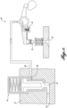
- the engine brake system 10 includes a solenoid valve 14 secured within a solenoid mounting portion 12 having an oil inlet line 16 and an oil outlet line 20.
- the solenoid valve 14 includes and inlet opening 24 at a bottom end of the valve that is in fluid communication with the oil inlet line 16, and an outlet opening 28 near a middle portion of the valve that is in fluid communication with the oil outlet line 20.
- the solenoid valve 14, when activated, allows pressurized engine oil to flow from the oil inlet line 16 to the oil outlet line 20 and thereafter to a control valve 18, such as a one-way check valve.
- the pressurized engine oil passes through the control valve 18 to extend a slave piston 22 to initiate the engine braking function.
- the slave piston 22 Upon pressure from the oil, the slave piston 22 extends and pushes down on an exhaust valve 26.
- the control valve 18 prevents oil from backing out of the system, i.e., the control valve 18 traps oil in the slave piston 22 to maintain it in an extended state.
- a master piston (not shown) positioned axially beneath the exhaust valve 26 moves between first and second positions in sync with the movement of the slave piston 22 and exhaust valve 26.
- the master piston retracts, and vice versa.
- Sufficient clearance exists such that when the slave piston 22 and master piston are in sync, the exhaust valve 26 does not interfere with the master piston. If the exhaust valve 26 hits the master piston, severe engine damage could occur. Accordingly, it can be appreciated that if the slave piston 22 is not functioning properly, the exhaust valve 26 could hit or interfere with the master piston.
- the slave piston 22 may function sub-optimally if the engine oil is not replaced as needed or other misuse occurs. In such suboptimal conditions, the slave piston 22 may wear, bind, etc., causing the slave piston 22 to either stick during the extension and retraction phases, or not fully extend or retract. Full extension of the slave piston 22 has a direct correlation with engine brake effectiveness. Moreover, stiction in at least one of the extension and retraction phases may cause lower power and may even destroy the engine if the exhaust valve 26 clashes with the master piston.
- US 2003/221644 A1 discloses an engine valve actuation system.
- the engine valve actuation system includes an intake valve that is moveable between a first position to prevent a flow of fluid and a second position to allow a flow of fluid.
- a cam assembly is configured to move the intake valve between the first position and the second position.
- a fluid actuator is configured to selectively prevent the intake valve from moving to the first position.
- a source of fluid is in fluid communication with the fluid actuator.
- a directional control valve is configured to control a flow of fluid between the source of fluid and the fluid actuator.
- a check valve is disposed between the directional control valve and the source of fluid, only allowing fluid flow from the fluid source to the directional control valve.
- a bleed orifice may be disposed between the directional control valve and the source of fluid, in parallel with the check valve.
- an engine brake test tool 40 formed in accordance with an exemplary embodiment of the present disclosure is depicted.
- the engine brake test tool 40 is suitable for testing the actuation of a slave piston to assess the health of an engine brake system.
- the engine brake test tool 40 is shown schematically in FIGURE 2 with a portion of the MX-11 engine brake system 10 of FIGURE 1 , wherein the solenoid valve 14 has been removed and replaced with the engine brake test tool 40.
- the engine brake test tool 40 may instead be used with any suitable engine brake system.
- valves other than a solenoid valve may be used. Accordingly, the illustrations and descriptions provided herein should not be seen as limiting the scope of the claimed subject matter.
- the engine brake test tool 40 is generally configured to allow pressurized fluid to flow from an outside fluid source (separate from the engine brake system 10) to the oil outlet line 20 for actuating the slave piston 22 while preventing pressurized engine oil from flowing from the oil inlet line 16 to the oil outlet line 20.
- an exemplary embodiment of the engine brake test tool 40 for carrying out the function of allowing outside pressurized fluid to flow to the slave piston 22 while preventing pressurized engine oil to flow to the slave piston 22 will now be described in detail.
- the engine brake test tool 40 includes a fitting 42 having a body 44 with a hollow interior that is generally shaped, sized, and configured to fit within a solenoid opening (not labeled) defined within the solenoid mounting portion 12 when the solenoid valve 14 is removed.
- the body 44 includes a first cylindrical portion 46 defining a lower portion thereof and a second enlarged cylindrical portion 48 defining an upper portion thereof.
- the first and second cylindrical portions 46 and 48 generally fit within correspondingly-shaped lower and upper bores of the solenoid opening.
- the body 44 may instead have any other shape to match a correspondingly shaped solenoid valve opening or other valve opening.
- the fitting 42 further includes a first, inlet opening 52 configured to be placed into communication with an outside pressurized fluid source (not shown), and a second, outlet opening 56 in fluid communication with the oil outlet line 20 of the engine brake system 10 when the fitting 42 is received within the solenoid opening.
- the inlet opening 52 is defined in the second cylindrical portion 48 such that it is accessible when the fitting 42 is disposed within the solenoid opening.
- the inlet opening 52 is centrally defined in an upper end of the second cylindrical portion 48 such that pressurized fluid can enter the interior of the body 44.
- the outlet opening 56 in the exemplary embodiment, is defined within the first cylindrical portion 46 such that it is in fluid communication with the oil outlet line 20 when the fitting 42 is received within the solenoid opening. In this manner, pressurized fluid may flow into the inlet opening 52, through the interior of the body 44, and out the outlet opening 56 to the oil outlet line 20 of the engine brake system 10.
- one or more sealing elements such as first and second O-rings 58 and 60, may be annularly disposed on the exterior of the first cylindrical portion 46 axially above and below the outlet opening 56. In this manner, pressurized fluid flows out of the outlet opening 56 and into oil outlet line 20 of the engine brake system 10 when using the engine brake test tool 40.
- the first O-ring 58 may be positioned against a shoulder defined between the intersection of the first and second cylindrical portions 46 and 48. With the first O-ring 58 positioned against the shoulder, the first O-ring 58 is maintained in its axial position on the test tool body 44 as it is moved downwardly into the solenoid opening.
- the second O-ring 60 may be disposed within an axial groove 62 defined on the exterior of the body 44 to secure it in its axial position below the outlet opening 56. Any other sealing elements or sealing assembly may instead be used.
- the fitting 42 when received within the solenoid opening, as shown generally in FIGURE 2 , may be secured within the solenoid opening in any suitable manner.
- the fitting 42 is secured within the solenoid opening with a clamp assembly 68.
- the clamp assembly 68 is generally configured to secure the fitting 42 to the solenoid mounting portion 12 (see FIGURE 2 ) when the fitting 42 is disposed within the solenoid opening.
- the claim assembly 68 includes a clamping plate 72 having a first, keyed portion 76 shaped and sized to engage an annular recess 74 defined within the second cylindrical portion 48 of the fitting 42.
- the second cylindrical portion 48 may have a sufficient axial length such that a portion of the second cylindrical portion 48 having the annular recess 74 protrudes from the upper surface of the solenoid mounting portion 12. In this manner, the keyed portion 76 can mate with the annular recess 74.
- the clamping plate 72 further includes a second, attachment portion 80 (opposite the keyed portion 76) configured for securing the clamping plate 72 to the solenoid mounting portion 12 or another suitable portion of the engine brake system 10.
- the second attachment portion 80 may include an opening 82 (threaded or non-threaded) for receiving a fastener 84, such as a bolt, for attachment to the solenoid mounting portion 12 or another suitable portion of the engine brake system 10.
- the fastener 84 passes through the opening 82 in the second attachment portion 80 and is thereafter secured within a threaded opening (not labeled) in the solenoid mounting portion 12. With the fastener 84 secured to the solenoid mounting portion 12 in this manner, and with the first keyed portion 76 mated with the annular recess 74, the fitting 42 is prevented from moving axially out of the solenoid opening.
- FIGURE 1 the engine is first turned off and the solenoid valve 14 is removed from the solenoid mounting portion 12. With the engine off, the fitting 42 is disposed within the opening defined by the missing solenoid valve 14, as shown in FIGURE 2 . The fitting 42 is secured axially within the solenoid valve opening by engaging the first keyed portion 76 of the clamping plate 72 with the annular recess 74 of the fitting body 44, and the fastener 84 is passed through the opening 82 in the clamping plate 72 and secured within a threaded opening in the solenoid mounting portion 12.
- the inlet opening 52 of the fitting 42 is placed into fluid communication with a pressurized fluid source, such as an air compressor or the like.
- a pressurized fluid source such as an air compressor or the like.
- the pressurized fluid flows into the inlet opening 52, out the outlet opening 56 of the fitting 42, and into the oil outlet line 20 of the engine brake system 10.
- the pressurized fluid flows past the control valve 18 to extend the slave piston 22 to mimic the initiation of the engine braking function.
- observations and measurements can be made as to the movement quality of the slave piston. For instance, observations regarding defect, abrasions, stiction, incomplete extension, etc., can all be made with the engine off.
- the slave piston 22 is tested in the actual environment of the engine brake system 10, which means that the system itself can also be checked for component installation issues, defects, etc.
- the components of the engine brake system 10, such as the slave piston 22, do not have to be removed from the engine brake system 10, thereby reducing cost and complexity.
- the present disclosure may also include references to directions, such as “forward,” “rearward,” “front,” “back,” “upward,” “downward,” “lateral,” “medial,” “in,” “out,” “extended,” “advanced,” “retracted,” “vertical,” “horizontal,” “proximal,” “distal,” “central,” etc. These references, and other similar references in the present disclosure, are only to assist in helping describe and understand the particular embodiment and are not intended to limit the present disclosure to these directions or locations.
- the present disclosure may also reference quantities and numbers. Unless specifically stated, such quantities and numbers are not to be considered restrictive, but exemplary of the possible quantities or numbers associated with the present disclosure. Also in this regard, the present disclosure may use the term “plurality” to reference a quantity or number. In this regard, the term “plurality” is meant to be any number that is more than one, for example, two, three, four, five, etc. In an embodiment, "about,” “approximately,” etc., means plus or minus 5% of the stated value.
Landscapes
- Engineering & Computer Science (AREA)
- Physics & Mathematics (AREA)
- General Physics & Mathematics (AREA)
- Mechanical Engineering (AREA)
- General Engineering & Computer Science (AREA)
- Chemical & Material Sciences (AREA)
- Combustion & Propulsion (AREA)
- Valves And Accessory Devices For Braking Systems (AREA)
- Braking Arrangements (AREA)
- Pinball Game Machines (AREA)
Claims (9)
- Outil d'essai de frein moteur (40) pour un système de frein moteur (10) présentant une vanne (14) fixée à l'intérieur d'une ouverture de vanne, la vanne (14) étant configurée pour permettre à de l'huile sous pression de s'écouler d'une conduite d'entrée d'huile (16) à une conduite de sortie d'huile (20), dans lequel la conduite de sortie d'huile (20) est configurée pour être couplée fluidiquement à un piston asservi (22), l'outil d'essai de frein moteur (40) comprenant :
un raccord (42) fixé à l'intérieur de l'ouverture de vanne lorsque la vanne (14) est retirée, le raccord (42) empêchant de l'huile sous pression de s'écouler entre la conduite d'entrée d'huile (16) et la conduite de sortie d'huile (20), le raccord (42) comprenant :une première ouverture (52) en communication fluidique avec une source de fluide sous pression ; etune seconde ouverture (56) en communication fluidique avec la première ouverture (52) et en communication fluidique avec la conduite de sortie d'huile (20),dans lequel la source de fluide sous pression est en communication fluidique avec le piston asservi (22) par l'intermédiaire de la première ouverture (52) et de la seconde ouverture (56) du raccord (42), la source de fluide sous pression faisant circuler de l'air sous pression à travers la première ouverture (52) dans le raccord (42) vers la seconde ouverture (56) dans le raccord (42) pour actionner le piston asservi (22). - Outil d'essai de frein moteur selon la revendication 1, dans lequel l'ouverture de vanne est une ouverture de vanne électromagnétique dans le système de frein moteur.
- Outil d'essai de frein moteur selon la revendication 1, comprenant en outre un ensemble de serrage configuré pour fixer de manière amovible le raccord à l'intérieur de l'ouverture de vanne.
- Outil d'essai de frein moteur selon la revendication 3, dans lequel l'ensemble de serrage inclut une plaque de serrage pouvant venir en prise avec un évidement annulaire du raccord, et au moins un élément de fixation configuré pour fixer la plaque de serrage à une partie du système de frein moteur.
- Outil d'essai de frein moteur selon la revendication 1, comprenant en outre au moins un élément d'étanchéité disposé sur un extérieur du raccord.
- Procédé d'essai d'un piston asservi (22) d'un système de frein moteur (10) présentant une vanne (14) fixée à l'intérieur d'une ouverture de vanne, la vanne (14) étant configurée pour permettre à de l'huile sous pression de s'écouler d'une conduite d'entrée d'huile (16) à une conduite de sortie d'huile (20), dans lequel la conduite de sortie d'huile (20) est configurée pour être couplée fluidiquement à un piston asservi (22), le procédé comprenant :la fixation d'un raccord (42) à l'intérieur de l'ouverture de vanne lorsque la vanne (14) est retirée, le raccord (42) présentant une première ouverture (52) configurée pour être placée en communication fluidique avec une source de fluide sous pression et une seconde ouverture (56) configurée pour être placée en communication fluidique avec la conduite de sortie d'huile (20) lorsque le raccord (42) est fixé à l'intérieur de l'ouverture de vanne, dans lequel le raccord (42) empêche de l'huile sous pression de s'écouler entre la conduite d'entrée d'huile (16) et la conduite de sortie d'huile (20) lorsque le raccord (42) est fixé à l'intérieur de l'ouverture de vanne ; etla circulation d'air sous pression de la première ouverture (52) dans le raccord (42) à la seconde ouverture (56) dans le raccord (42) pour actionner le piston asservi (22).
- Procédé selon la revendication 6, comprenant en outre l'observation de l'actionnement du piston asservi pour identifier au moins un élément parmi des défauts, des abrasions, un frottement statique, et une extension incomplète.
- Procédé selon la revendication 6, comprenant en outre la fixation du raccord à l'intérieur de l'ouverture de vanne avec un ensemble de serrage.
- Procédé selon la revendication 6, comprenant en outre l'étanchéification du raccord à l'intérieur de l'ouverture de vanne.
Applications Claiming Priority (2)
| Application Number | Priority Date | Filing Date | Title |
|---|---|---|---|
| US15/475,036 US10393626B2 (en) | 2017-03-30 | 2017-03-30 | Engine brake test tool |
| PCT/US2018/025078 WO2018183634A1 (fr) | 2017-03-30 | 2018-03-29 | Outil d'essai de frein moteur |
Publications (3)
| Publication Number | Publication Date |
|---|---|
| EP3601991A1 EP3601991A1 (fr) | 2020-02-05 |
| EP3601991A4 EP3601991A4 (fr) | 2021-01-20 |
| EP3601991B1 true EP3601991B1 (fr) | 2023-11-29 |
Family
ID=63669180
Family Applications (1)
| Application Number | Title | Priority Date | Filing Date |
|---|---|---|---|
| EP18776992.2A Active EP3601991B1 (fr) | 2017-03-30 | 2018-03-29 | Outil d'essai de frein moteur |
Country Status (4)
| Country | Link |
|---|---|
| US (1) | US10393626B2 (fr) |
| EP (1) | EP3601991B1 (fr) |
| BR (1) | BR112019020574A2 (fr) |
| WO (1) | WO2018183634A1 (fr) |
Families Citing this family (1)
| Publication number | Priority date | Publication date | Assignee | Title |
|---|---|---|---|---|
| CN114235361A (zh) * | 2021-11-30 | 2022-03-25 | 潍柴动力股份有限公司 | 一种发动机活塞及发动机活塞疲劳试验装置 |
Family Cites Families (11)
| Publication number | Priority date | Publication date | Assignee | Title |
|---|---|---|---|---|
| US4655178A (en) * | 1985-05-08 | 1987-04-07 | Meneely Vincent A | Anti-lash adjuster |
| US5000145A (en) * | 1989-12-05 | 1991-03-19 | Quenneville Raymond N | Compression release retarding system |
| US5186141A (en) * | 1992-05-04 | 1993-02-16 | Jacobs Brake Technology Corporation | Engine brake timing control mechanism |
| US5477824A (en) | 1994-07-14 | 1995-12-26 | Cummins Engine Company, Inc. | Solenoid valve for compression-type engine retarder |
| US5462025A (en) * | 1994-09-28 | 1995-10-31 | Diesel Engine Retarders, Inc. | Hydraulic circuits for compression release engine brakes |
| DE69841570D1 (de) * | 1997-01-29 | 2010-05-06 | Hino Motors Ltd | Abgasrückführungsvorrichtung |
| KR100428159B1 (ko) | 2001-11-01 | 2004-04-28 | 현대자동차주식회사 | 차량의 보조브레이크 |
| US6907851B2 (en) * | 2002-05-14 | 2005-06-21 | Caterpillar Inc | Engine valve actuation system |
| RU2457348C2 (ru) | 2007-10-22 | 2012-07-27 | Вольво Ластвагнар Аб | Контроль моторного тормоза |
| BRPI0917420B1 (pt) * | 2008-07-31 | 2020-02-18 | Pacbrake Company | Sistema de freio de compressão-liberação para a operação de pelo menos uma válvula de exaustão de um motor de combustão interna |
| WO2016044748A1 (fr) * | 2014-09-18 | 2016-03-24 | Jacobs Vehicle Systems, Inc. | Ensemble à mouvement perdu dans un pont de soupapes à utiliser avec un train de soupapes comprenant un rattrapeur de jeu hydraulique |
-
2017
- 2017-03-30 US US15/475,036 patent/US10393626B2/en active Active
-
2018
- 2018-03-29 EP EP18776992.2A patent/EP3601991B1/fr active Active
- 2018-03-29 BR BR112019020574A patent/BR112019020574A2/pt not_active Application Discontinuation
- 2018-03-29 WO PCT/US2018/025078 patent/WO2018183634A1/fr not_active Ceased
Also Published As
| Publication number | Publication date |
|---|---|
| EP3601991A1 (fr) | 2020-02-05 |
| EP3601991A4 (fr) | 2021-01-20 |
| WO2018183634A1 (fr) | 2018-10-04 |
| US20180283989A1 (en) | 2018-10-04 |
| BR112019020574A2 (pt) | 2020-05-19 |
| US10393626B2 (en) | 2019-08-27 |
Similar Documents
| Publication | Publication Date | Title |
|---|---|---|
| KR102300778B1 (ko) | 증력 기구가 부착된 유체압 실린더 | |
| US9057447B2 (en) | Low pressure hot tap pipeline isolation | |
| US9109717B2 (en) | Electronically controlled pressure relief valve | |
| WO2014059975A1 (fr) | Soupape de commande pour déphaseur d'arbre à cames | |
| US9915373B2 (en) | Electronically controlled pressure relief valve | |
| EP3601991B1 (fr) | Outil d'essai de frein moteur | |
| US9394928B2 (en) | Dynamic seal wear mitigation system | |
| US11203329B2 (en) | Hydraulic master cylinder, a vehicle braking system and a vehicle | |
| US9976579B2 (en) | Ram air turbine actuator system | |
| WO2020154413A1 (fr) | Vis de purge de frein et outil comprenant des raccords à connexion rapide | |
| US6868772B2 (en) | Fluid control valve | |
| EP2891815B1 (fr) | Système de frein ou de couplage et procédé de fonctionnement d'un tel système | |
| US5279124A (en) | Cartridge for a master cylinder assembly for a fluid pressure control system and method for installing a master cylinder assembly in a fluid pressure control system | |
| US11822357B2 (en) | Pilot-controlled coolant valve | |
| EP3613999B1 (fr) | Compensation thermique vérifiable extérieurement d'actionneur d'ouverture de capot | |
| US9707946B2 (en) | Surge brake actuator | |
| US10830365B2 (en) | Bi-directional inline check valve | |
| RU2216676C2 (ru) | Быстроразъемный агрегат | |
| US2216570A (en) | Safety device | |
| US3628423A (en) | Power brake booster | |
| EP0214765B1 (fr) | Systèmes d'actionnement de freinage pour véhicules | |
| JP2016084873A (ja) | 電磁開閉弁及びこれを用いた潤滑ポンプ装置 | |
| US9764671B2 (en) | Unloading relief valve | |
| EP0291285A1 (fr) | Actuateur de frein | |
| US20180017193A1 (en) | Seal member for a hydraulic fluid actuator |
Legal Events
| Date | Code | Title | Description |
|---|---|---|---|
| STAA | Information on the status of an ep patent application or granted ep patent |
Free format text: STATUS: THE INTERNATIONAL PUBLICATION HAS BEEN MADE |
|
| PUAI | Public reference made under article 153(3) epc to a published international application that has entered the european phase |
Free format text: ORIGINAL CODE: 0009012 |
|
| STAA | Information on the status of an ep patent application or granted ep patent |
Free format text: STATUS: REQUEST FOR EXAMINATION WAS MADE |
|
| 17P | Request for examination filed |
Effective date: 20191029 |
|
| AK | Designated contracting states |
Kind code of ref document: A1 Designated state(s): AL AT BE BG CH CY CZ DE DK EE ES FI FR GB GR HR HU IE IS IT LI LT LU LV MC MK MT NL NO PL PT RO RS SE SI SK SM TR |
|
| AX | Request for extension of the european patent |
Extension state: BA ME |
|
| DAV | Request for validation of the european patent (deleted) | ||
| DAX | Request for extension of the european patent (deleted) | ||
| A4 | Supplementary search report drawn up and despatched |
Effective date: 20201218 |
|
| RIC1 | Information provided on ipc code assigned before grant |
Ipc: F01L 13/06 20060101AFI20201214BHEP Ipc: G01M 15/02 20060101ALN20201214BHEP Ipc: F02D 13/04 20060101ALN20201214BHEP |
|
| REG | Reference to a national code |
Ref country code: DE Ref legal event code: R079 Free format text: PREVIOUS MAIN CLASS: G01M0015020000 Ipc: F01L0013060000 Ref country code: DE Ref legal event code: R079 Ref document number: 602018061858 Country of ref document: DE Free format text: PREVIOUS MAIN CLASS: G01M0015020000 Ipc: F01L0013060000 |
|
| GRAP | Despatch of communication of intention to grant a patent |
Free format text: ORIGINAL CODE: EPIDOSNIGR1 |
|
| STAA | Information on the status of an ep patent application or granted ep patent |
Free format text: STATUS: GRANT OF PATENT IS INTENDED |
|
| RIC1 | Information provided on ipc code assigned before grant |
Ipc: F02D 13/04 20060101ALN20230531BHEP Ipc: G01M 15/02 20060101ALN20230531BHEP Ipc: F01L 13/06 20060101AFI20230531BHEP |
|
| INTG | Intention to grant announced |
Effective date: 20230623 |
|
| GRAS | Grant fee paid |
Free format text: ORIGINAL CODE: EPIDOSNIGR3 |
|
| GRAA | (expected) grant |
Free format text: ORIGINAL CODE: 0009210 |
|
| STAA | Information on the status of an ep patent application or granted ep patent |
Free format text: STATUS: THE PATENT HAS BEEN GRANTED |
|
| AK | Designated contracting states |
Kind code of ref document: B1 Designated state(s): AL AT BE BG CH CY CZ DE DK EE ES FI FR GB GR HR HU IE IS IT LI LT LU LV MC MK MT NL NO PL PT RO RS SE SI SK SM TR |
|
| REG | Reference to a national code |
Ref country code: GB Ref legal event code: FG4D |
|
| REG | Reference to a national code |
Ref country code: CH Ref legal event code: EP |
|
| REG | Reference to a national code |
Ref country code: DE Ref legal event code: R096 Ref document number: 602018061858 Country of ref document: DE |
|
| P01 | Opt-out of the competence of the unified patent court (upc) registered |
Effective date: 20231109 |
|
| REG | Reference to a national code |
Ref country code: IE Ref legal event code: FG4D |
|
| REG | Reference to a national code |
Ref country code: NL Ref legal event code: FP |
|
| REG | Reference to a national code |
Ref country code: LT Ref legal event code: MG9D |
|
| PG25 | Lapsed in a contracting state [announced via postgrant information from national office to epo] |
Ref country code: GR Free format text: LAPSE BECAUSE OF FAILURE TO SUBMIT A TRANSLATION OF THE DESCRIPTION OR TO PAY THE FEE WITHIN THE PRESCRIBED TIME-LIMIT Effective date: 20240301 |
|
| PG25 | Lapsed in a contracting state [announced via postgrant information from national office to epo] |
Ref country code: IS Free format text: LAPSE BECAUSE OF FAILURE TO SUBMIT A TRANSLATION OF THE DESCRIPTION OR TO PAY THE FEE WITHIN THE PRESCRIBED TIME-LIMIT Effective date: 20240329 |
|
| PG25 | Lapsed in a contracting state [announced via postgrant information from national office to epo] |
Ref country code: LT Free format text: LAPSE BECAUSE OF FAILURE TO SUBMIT A TRANSLATION OF THE DESCRIPTION OR TO PAY THE FEE WITHIN THE PRESCRIBED TIME-LIMIT Effective date: 20231129 |
|
| PG25 | Lapsed in a contracting state [announced via postgrant information from national office to epo] |
Ref country code: ES Free format text: LAPSE BECAUSE OF FAILURE TO SUBMIT A TRANSLATION OF THE DESCRIPTION OR TO PAY THE FEE WITHIN THE PRESCRIBED TIME-LIMIT Effective date: 20231129 |
|
| PG25 | Lapsed in a contracting state [announced via postgrant information from national office to epo] |
Ref country code: LT Free format text: LAPSE BECAUSE OF FAILURE TO SUBMIT A TRANSLATION OF THE DESCRIPTION OR TO PAY THE FEE WITHIN THE PRESCRIBED TIME-LIMIT Effective date: 20231129 Ref country code: IS Free format text: LAPSE BECAUSE OF FAILURE TO SUBMIT A TRANSLATION OF THE DESCRIPTION OR TO PAY THE FEE WITHIN THE PRESCRIBED TIME-LIMIT Effective date: 20240329 Ref country code: GR Free format text: LAPSE BECAUSE OF FAILURE TO SUBMIT A TRANSLATION OF THE DESCRIPTION OR TO PAY THE FEE WITHIN THE PRESCRIBED TIME-LIMIT Effective date: 20240301 Ref country code: ES Free format text: LAPSE BECAUSE OF FAILURE TO SUBMIT A TRANSLATION OF THE DESCRIPTION OR TO PAY THE FEE WITHIN THE PRESCRIBED TIME-LIMIT Effective date: 20231129 Ref country code: BG Free format text: LAPSE BECAUSE OF FAILURE TO SUBMIT A TRANSLATION OF THE DESCRIPTION OR TO PAY THE FEE WITHIN THE PRESCRIBED TIME-LIMIT Effective date: 20240229 |
|
| REG | Reference to a national code |
Ref country code: AT Ref legal event code: MK05 Ref document number: 1636326 Country of ref document: AT Kind code of ref document: T Effective date: 20231129 |
|
| PG25 | Lapsed in a contracting state [announced via postgrant information from national office to epo] |
Ref country code: SE Free format text: LAPSE BECAUSE OF FAILURE TO SUBMIT A TRANSLATION OF THE DESCRIPTION OR TO PAY THE FEE WITHIN THE PRESCRIBED TIME-LIMIT Effective date: 20231129 Ref country code: RS Free format text: LAPSE BECAUSE OF FAILURE TO SUBMIT A TRANSLATION OF THE DESCRIPTION OR TO PAY THE FEE WITHIN THE PRESCRIBED TIME-LIMIT Effective date: 20231129 Ref country code: PL Free format text: LAPSE BECAUSE OF FAILURE TO SUBMIT A TRANSLATION OF THE DESCRIPTION OR TO PAY THE FEE WITHIN THE PRESCRIBED TIME-LIMIT Effective date: 20231129 Ref country code: NO Free format text: LAPSE BECAUSE OF FAILURE TO SUBMIT A TRANSLATION OF THE DESCRIPTION OR TO PAY THE FEE WITHIN THE PRESCRIBED TIME-LIMIT Effective date: 20240229 Ref country code: LV Free format text: LAPSE BECAUSE OF FAILURE TO SUBMIT A TRANSLATION OF THE DESCRIPTION OR TO PAY THE FEE WITHIN THE PRESCRIBED TIME-LIMIT Effective date: 20231129 Ref country code: HR Free format text: LAPSE BECAUSE OF FAILURE TO SUBMIT A TRANSLATION OF THE DESCRIPTION OR TO PAY THE FEE WITHIN THE PRESCRIBED TIME-LIMIT Effective date: 20231129 |
|
| PG25 | Lapsed in a contracting state [announced via postgrant information from national office to epo] |
Ref country code: DK Free format text: LAPSE BECAUSE OF FAILURE TO SUBMIT A TRANSLATION OF THE DESCRIPTION OR TO PAY THE FEE WITHIN THE PRESCRIBED TIME-LIMIT Effective date: 20231129 |
|
| PG25 | Lapsed in a contracting state [announced via postgrant information from national office to epo] |
Ref country code: AT Free format text: LAPSE BECAUSE OF FAILURE TO SUBMIT A TRANSLATION OF THE DESCRIPTION OR TO PAY THE FEE WITHIN THE PRESCRIBED TIME-LIMIT Effective date: 20231129 Ref country code: CZ Free format text: LAPSE BECAUSE OF FAILURE TO SUBMIT A TRANSLATION OF THE DESCRIPTION OR TO PAY THE FEE WITHIN THE PRESCRIBED TIME-LIMIT Effective date: 20231129 |
|
| PG25 | Lapsed in a contracting state [announced via postgrant information from national office to epo] |
Ref country code: SK Free format text: LAPSE BECAUSE OF FAILURE TO SUBMIT A TRANSLATION OF THE DESCRIPTION OR TO PAY THE FEE WITHIN THE PRESCRIBED TIME-LIMIT Effective date: 20231129 |
|
| PG25 | Lapsed in a contracting state [announced via postgrant information from national office to epo] |
Ref country code: SM Free format text: LAPSE BECAUSE OF FAILURE TO SUBMIT A TRANSLATION OF THE DESCRIPTION OR TO PAY THE FEE WITHIN THE PRESCRIBED TIME-LIMIT Effective date: 20231129 Ref country code: SK Free format text: LAPSE BECAUSE OF FAILURE TO SUBMIT A TRANSLATION OF THE DESCRIPTION OR TO PAY THE FEE WITHIN THE PRESCRIBED TIME-LIMIT Effective date: 20231129 Ref country code: RO Free format text: LAPSE BECAUSE OF FAILURE TO SUBMIT A TRANSLATION OF THE DESCRIPTION OR TO PAY THE FEE WITHIN THE PRESCRIBED TIME-LIMIT Effective date: 20231129 Ref country code: IT Free format text: LAPSE BECAUSE OF FAILURE TO SUBMIT A TRANSLATION OF THE DESCRIPTION OR TO PAY THE FEE WITHIN THE PRESCRIBED TIME-LIMIT Effective date: 20231129 Ref country code: EE Free format text: LAPSE BECAUSE OF FAILURE TO SUBMIT A TRANSLATION OF THE DESCRIPTION OR TO PAY THE FEE WITHIN THE PRESCRIBED TIME-LIMIT Effective date: 20231129 Ref country code: DK Free format text: LAPSE BECAUSE OF FAILURE TO SUBMIT A TRANSLATION OF THE DESCRIPTION OR TO PAY THE FEE WITHIN THE PRESCRIBED TIME-LIMIT Effective date: 20231129 Ref country code: CZ Free format text: LAPSE BECAUSE OF FAILURE TO SUBMIT A TRANSLATION OF THE DESCRIPTION OR TO PAY THE FEE WITHIN THE PRESCRIBED TIME-LIMIT Effective date: 20231129 Ref country code: AT Free format text: LAPSE BECAUSE OF FAILURE TO SUBMIT A TRANSLATION OF THE DESCRIPTION OR TO PAY THE FEE WITHIN THE PRESCRIBED TIME-LIMIT Effective date: 20231129 |
|
| PG25 | Lapsed in a contracting state [announced via postgrant information from national office to epo] |
Ref country code: PT Free format text: LAPSE BECAUSE OF FAILURE TO SUBMIT A TRANSLATION OF THE DESCRIPTION OR TO PAY THE FEE WITHIN THE PRESCRIBED TIME-LIMIT Effective date: 20240401 |
|
| PG25 | Lapsed in a contracting state [announced via postgrant information from national office to epo] |
Ref country code: PT Free format text: LAPSE BECAUSE OF FAILURE TO SUBMIT A TRANSLATION OF THE DESCRIPTION OR TO PAY THE FEE WITHIN THE PRESCRIBED TIME-LIMIT Effective date: 20240401 |
|
| REG | Reference to a national code |
Ref country code: DE Ref legal event code: R097 Ref document number: 602018061858 Country of ref document: DE |
|
| PLBE | No opposition filed within time limit |
Free format text: ORIGINAL CODE: 0009261 |
|
| STAA | Information on the status of an ep patent application or granted ep patent |
Free format text: STATUS: NO OPPOSITION FILED WITHIN TIME LIMIT |
|
| PG25 | Lapsed in a contracting state [announced via postgrant information from national office to epo] |
Ref country code: SI Free format text: LAPSE BECAUSE OF FAILURE TO SUBMIT A TRANSLATION OF THE DESCRIPTION OR TO PAY THE FEE WITHIN THE PRESCRIBED TIME-LIMIT Effective date: 20231129 |
|
| PG25 | Lapsed in a contracting state [announced via postgrant information from national office to epo] |
Ref country code: SI Free format text: LAPSE BECAUSE OF FAILURE TO SUBMIT A TRANSLATION OF THE DESCRIPTION OR TO PAY THE FEE WITHIN THE PRESCRIBED TIME-LIMIT Effective date: 20231129 |
|
| REG | Reference to a national code |
Ref country code: CH Ref legal event code: PL |
|
| 26N | No opposition filed |
Effective date: 20240830 |
|
| PG25 | Lapsed in a contracting state [announced via postgrant information from national office to epo] |
Ref country code: LU Free format text: LAPSE BECAUSE OF NON-PAYMENT OF DUE FEES Effective date: 20240329 |
|
| PG25 | Lapsed in a contracting state [announced via postgrant information from national office to epo] |
Ref country code: MC Free format text: LAPSE BECAUSE OF FAILURE TO SUBMIT A TRANSLATION OF THE DESCRIPTION OR TO PAY THE FEE WITHIN THE PRESCRIBED TIME-LIMIT Effective date: 20231129 |
|
| PG25 | Lapsed in a contracting state [announced via postgrant information from national office to epo] |
Ref country code: MC Free format text: LAPSE BECAUSE OF FAILURE TO SUBMIT A TRANSLATION OF THE DESCRIPTION OR TO PAY THE FEE WITHIN THE PRESCRIBED TIME-LIMIT Effective date: 20231129 Ref country code: LU Free format text: LAPSE BECAUSE OF NON-PAYMENT OF DUE FEES Effective date: 20240329 |
|
| REG | Reference to a national code |
Ref country code: BE Ref legal event code: MM Effective date: 20240331 |
|
| PG25 | Lapsed in a contracting state [announced via postgrant information from national office to epo] |
Ref country code: BE Free format text: LAPSE BECAUSE OF NON-PAYMENT OF DUE FEES Effective date: 20240331 |
|
| PG25 | Lapsed in a contracting state [announced via postgrant information from national office to epo] |
Ref country code: IE Free format text: LAPSE BECAUSE OF NON-PAYMENT OF DUE FEES Effective date: 20240329 |
|
| PG25 | Lapsed in a contracting state [announced via postgrant information from national office to epo] |
Ref country code: IE Free format text: LAPSE BECAUSE OF NON-PAYMENT OF DUE FEES Effective date: 20240329 Ref country code: BE Free format text: LAPSE BECAUSE OF NON-PAYMENT OF DUE FEES Effective date: 20240331 Ref country code: CH Free format text: LAPSE BECAUSE OF NON-PAYMENT OF DUE FEES Effective date: 20240331 |
|
| PG25 | Lapsed in a contracting state [announced via postgrant information from national office to epo] |
Ref country code: CY Free format text: LAPSE BECAUSE OF FAILURE TO SUBMIT A TRANSLATION OF THE DESCRIPTION OR TO PAY THE FEE WITHIN THE PRESCRIBED TIME-LIMIT; INVALID AB INITIO Effective date: 20180329 |
|
| PG25 | Lapsed in a contracting state [announced via postgrant information from national office to epo] |
Ref country code: HU Free format text: LAPSE BECAUSE OF FAILURE TO SUBMIT A TRANSLATION OF THE DESCRIPTION OR TO PAY THE FEE WITHIN THE PRESCRIBED TIME-LIMIT; INVALID AB INITIO Effective date: 20180329 |
|
| PG25 | Lapsed in a contracting state [announced via postgrant information from national office to epo] |
Ref country code: FI Free format text: LAPSE BECAUSE OF FAILURE TO SUBMIT A TRANSLATION OF THE DESCRIPTION OR TO PAY THE FEE WITHIN THE PRESCRIBED TIME-LIMIT Effective date: 20231129 |
|
| PG25 | Lapsed in a contracting state [announced via postgrant information from national office to epo] |
Ref country code: TR Free format text: LAPSE BECAUSE OF FAILURE TO SUBMIT A TRANSLATION OF THE DESCRIPTION OR TO PAY THE FEE WITHIN THE PRESCRIBED TIME-LIMIT Effective date: 20231129 |
|
| PGFP | Annual fee paid to national office [announced via postgrant information from national office to epo] |
Ref country code: GB Payment date: 20260327 Year of fee payment: 9 |
|
| PGFP | Annual fee paid to national office [announced via postgrant information from national office to epo] |
Ref country code: DE Payment date: 20260327 Year of fee payment: 9 |
|
| PGFP | Annual fee paid to national office [announced via postgrant information from national office to epo] |
Ref country code: NL Payment date: 20260326 Year of fee payment: 9 |
|
| PGFP | Annual fee paid to national office [announced via postgrant information from national office to epo] |
Ref country code: FR Payment date: 20260325 Year of fee payment: 9 |