EP3602008B1 - Atemgasmonitor mit automatisierter und unauffälliger filterkalibrierung - Google Patents
Atemgasmonitor mit automatisierter und unauffälliger filterkalibrierung Download PDFInfo
- Publication number
- EP3602008B1 EP3602008B1 EP18718578.0A EP18718578A EP3602008B1 EP 3602008 B1 EP3602008 B1 EP 3602008B1 EP 18718578 A EP18718578 A EP 18718578A EP 3602008 B1 EP3602008 B1 EP 3602008B1
- Authority
- EP
- European Patent Office
- Prior art keywords
- bandpass filter
- infrared light
- line bandpass
- path
- rgm
- Prior art date
- Legal status (The legal status is an assumption and is not a legal conclusion. Google has not performed a legal analysis and makes no representation as to the accuracy of the status listed.)
- Not-in-force
Links
Images

Classifications
-
- G—PHYSICS
- G01—MEASURING; TESTING
- G01N—INVESTIGATING OR ANALYSING MATERIALS BY DETERMINING THEIR CHEMICAL OR PHYSICAL PROPERTIES
- G01N21/00—Investigating or analysing materials by the use of optical means, i.e. using sub-millimetre waves, infrared, visible or ultraviolet light
- G01N21/17—Systems in which incident light is modified in accordance with the properties of the material investigated
- G01N21/25—Colour; Spectral properties, i.e. comparison of effect of material on the light at two or more different wavelengths or wavelength bands
- G01N21/31—Investigating relative effect of material at wavelengths characteristic of specific elements or molecules, e.g. atomic absorption spectrometry
- G01N21/35—Investigating relative effect of material at wavelengths characteristic of specific elements or molecules, e.g. atomic absorption spectrometry using infrared light
- G01N21/3504—Investigating relative effect of material at wavelengths characteristic of specific elements or molecules, e.g. atomic absorption spectrometry using infrared light for analysing gases, e.g. multi-gas analysis
-
- G—PHYSICS
- G01—MEASURING; TESTING
- G01N—INVESTIGATING OR ANALYSING MATERIALS BY DETERMINING THEIR CHEMICAL OR PHYSICAL PROPERTIES
- G01N33/00—Investigating or analysing materials by specific methods not covered by groups G01N1/00 - G01N31/00
- G01N33/0004—Gaseous mixtures, e.g. polluted air
- G01N33/0006—Calibrating gas analysers
-
- A—HUMAN NECESSITIES
- A61—MEDICAL OR VETERINARY SCIENCE; HYGIENE
- A61B—DIAGNOSIS; SURGERY; IDENTIFICATION
- A61B5/00—Measuring for diagnostic purposes; Identification of persons
- A61B5/08—Measuring devices for evaluating the respiratory organs
-
- A—HUMAN NECESSITIES
- A61—MEDICAL OR VETERINARY SCIENCE; HYGIENE
- A61B—DIAGNOSIS; SURGERY; IDENTIFICATION
- A61B5/00—Measuring for diagnostic purposes; Identification of persons
- A61B5/08—Measuring devices for evaluating the respiratory organs
- A61B5/082—Evaluation by breath analysis, e.g. determination of the chemical composition of exhaled breath
-
- A—HUMAN NECESSITIES
- A61—MEDICAL OR VETERINARY SCIENCE; HYGIENE
- A61B—DIAGNOSIS; SURGERY; IDENTIFICATION
- A61B5/00—Measuring for diagnostic purposes; Identification of persons
- A61B5/08—Measuring devices for evaluating the respiratory organs
- A61B5/097—Devices for facilitating collection of breath or for directing breath into or through measuring devices
-
- A—HUMAN NECESSITIES
- A61—MEDICAL OR VETERINARY SCIENCE; HYGIENE
- A61M—DEVICES FOR INTRODUCING MEDIA INTO, OR ONTO, THE BODY; DEVICES FOR TRANSDUCING BODY MEDIA OR FOR TAKING MEDIA FROM THE BODY; DEVICES FOR PRODUCING OR ENDING SLEEP OR STUPOR
- A61M16/00—Devices for influencing the respiratory system of patients by gas treatment, e.g. ventilators; Tracheal tubes
-
- G—PHYSICS
- G01—MEASURING; TESTING
- G01N—INVESTIGATING OR ANALYSING MATERIALS BY DETERMINING THEIR CHEMICAL OR PHYSICAL PROPERTIES
- G01N21/00—Investigating or analysing materials by the use of optical means, i.e. using sub-millimetre waves, infrared, visible or ultraviolet light
- G01N21/17—Systems in which incident light is modified in accordance with the properties of the material investigated
- G01N21/25—Colour; Spectral properties, i.e. comparison of effect of material on the light at two or more different wavelengths or wavelength bands
- G01N21/31—Investigating relative effect of material at wavelengths characteristic of specific elements or molecules, e.g. atomic absorption spectrometry
- G01N21/35—Investigating relative effect of material at wavelengths characteristic of specific elements or molecules, e.g. atomic absorption spectrometry using infrared light
- G01N21/3504—Investigating relative effect of material at wavelengths characteristic of specific elements or molecules, e.g. atomic absorption spectrometry using infrared light for analysing gases, e.g. multi-gas analysis
- G01N21/3518—Devices using gas filter correlation techniques; Devices using gas pressure modulation techniques
-
- A—HUMAN NECESSITIES
- A61—MEDICAL OR VETERINARY SCIENCE; HYGIENE
- A61B—DIAGNOSIS; SURGERY; IDENTIFICATION
- A61B2560/00—Constructional details of operational features of apparatus; Accessories for medical measuring apparatus
- A61B2560/02—Operational features
- A61B2560/0223—Operational features of calibration, e.g. protocols for calibrating sensors
-
- A—HUMAN NECESSITIES
- A61—MEDICAL OR VETERINARY SCIENCE; HYGIENE
- A61B—DIAGNOSIS; SURGERY; IDENTIFICATION
- A61B5/00—Measuring for diagnostic purposes; Identification of persons
- A61B5/08—Measuring devices for evaluating the respiratory organs
- A61B5/083—Measuring rate of metabolism by using breath test, e.g. measuring rate of oxygen consumption
- A61B5/0833—Measuring rate of oxygen consumption
-
- A—HUMAN NECESSITIES
- A61—MEDICAL OR VETERINARY SCIENCE; HYGIENE
- A61B—DIAGNOSIS; SURGERY; IDENTIFICATION
- A61B5/00—Measuring for diagnostic purposes; Identification of persons
- A61B5/08—Measuring devices for evaluating the respiratory organs
- A61B5/083—Measuring rate of metabolism by using breath test, e.g. measuring rate of oxygen consumption
- A61B5/0836—Measuring rate of CO2 production
Definitions
- RGM respiration gas monitor
- Respiration Gas Monitor (RGM) devices are used for measuring partial pressure or concentration of carbon dioxide (CO 2 ) in respired air, or some other respired gas such as oxygen (O 2 ), nitrous oxide (N 2 O), or an administered anesthetic gas.
- An RGM device for measuring CO 2 is commonly referred to as a capnometer.
- Various gas component detection technologies may be employed.
- an infrared light source launches broadband infrared light that passes through a sampling cell through which respired air flows.
- the opposing optical detector module includes a narrowband filter and an infrared detector. The filter is tuned to pass a wavelength that is strongly absorbed by the target gas, e.g. 4.3 micron for CO 2 .
- the optical detector is calibrated by measuring a reference signal in the absence of the target gas.
- This entails diverting the respired air flow from the sampling cell, and introducing flow of a reference gas such as air or nitrogen through the sampling cell.
- the reference gas is chosen to have negligible concentration of the target gas (e.g. negligible CO 2 in the case of a capnometer). Consequently, the measured signal output by the optical detector with the reference gas flowing is the maximum value, as there is negligible absorption by the target gas.
- the ratio of the signal measured with the infrared light launched through the respired air flow versus the reference signal measured with the infrared light launched through the reference gas flow provides the signal reduction due to infrared absorption by the target gas in the respired air flow.
- Document US 3 539 804 A discloses an example of a reference detector and an analytical detector combined in a compensation circuit instead of a single detector together with a filter switching device and numerical compensation.
- a respiration gas monitor (RGM) device comprises a respired air flow path for carrying respired air, an infrared light source arranged to launch infrared light through the respired air flow path, and an optical detector arranged to detect the infrared light after passing through the respired air flow path.
- An absorption line bandpass filter has a passband that encompasses an absorption line of a target gas.
- a reference line bandpass filter has a passband over which the respired air is transparent.
- a control device is operative to switch the RGM device between: a monitoring state in which the absorption line bandpass filter is in the path of the infrared light and the reference line bandpass filter is not in the path of the infrared light; and a calibration state in which the reference line bandpass filter is in the path of the infrared light and the absorption line bandpass filter is not in the path of the infrared light; and characterised by an electro-optical beam steering device operable at: a first electric bias implementing the monitoring state by steering the infrared light to an optical path that passes through the absorption line bandpass filter and does not pass through the reference line bandpass filter, and a second electric bias implementing the calibration state by steering the infrared light to an optical path that passes through the reference line bandpass filter and does not pass through the absorption line bandpass filter.
- a method of operating a respiration gas monitor (RGM) device is disclosed.
- Respired air is flowed through a respired air flow path.
- Infrared light is launched through the respired air flow path.
- target gas monitoring is performed, including measuring an infrared transmission signal indicating transmission of the launched infrared light through the respired air flow path with an absorption line bandpass filter disposed in the path of the infrared light and determining a value for the target gas in the respired air from the infrared transmission signal and a reference infrared signal.
- a calibration is performed including measuring the reference infrared signal indicating transmission of the launched infrared light through the respired air flow path with a reference line bandpass filter disposed in the path of the infrared light; characterised by performing the target gas monitoring by operating an electro-optic beam steering device to steer the infrared light to an optical path that passes through the absorption line bandpass filter and does not pass through the reference line bandpass filter; and performing the calibration by operating the electro-optic beam steering device to steer the infrared light to an optical path that passes through the reference line bandpass filter and does not pass through the absorption line bandpass filter.
- One advantage resides in providing more accurate monitoring of carbon dioxide or another target gas in respired air.
- RGM respiration gas monitor
- Another advantage resides in providing an RGM device that does not require connection to nitrogen or another calibration gas.
- Another advantage resides in providing an RGM device in which the respired gas flow through the RGM device is not interrupted to perform calibration.
- a given embodiment may provide none, one, two, more, or all of the foregoing advantages, and/or may provide other advantages as will become apparent to one of ordinary skill in the art upon reading and understanding the present disclosure.
- the invention may take form in various components and arrangements of components, and in various steps and arrangements of steps.
- the drawings are only for purposes of illustrating the preferred embodiments and are not to be construed as limiting the invention.
- the infrared light source typically includes an infrared emitting element (e.g. a ceramic element) that is resistively heated by conducting an electrical current pulse train through the infrared element.
- the infrared element is resistively heated is to a temperature effective to produce broadband blackbody radiation with strong emission in the infrared. This infrared emission is strongly dependent on the precise temperature of the heated infrared element.
- the temperature of the heated infrared emitting element can drift over time during operation of the RGM device.
- the infrared light detector may be a lead selenide (PbSe) detector, a microbolometer, thermocouple, pyroelectric detector, or the like, and its sensitivity is also usually strongly temperature dependent. The detector temperature can also drift over time during operation of the RGM device. Depending upon the thermal stabilities of the IR source and sensor, the calibration of the optical detection cell may need to be repeated at intervals as frequent as every few minutes to tens of minutes to ensure sufficient accuracy for robust medical monitoring of a critically ill patient.
- PbSe lead selenide
- the calibration of the optical detection cell is performed by flow switching, in which the respired air flow is diverted away from the sampling cell and the reference gas flow (e.g. nitrogen gas or air) is flowed through the sampling cell.
- the reference gas flow e.g. nitrogen gas or air
- the reference gas must be available in the patient's hospital room and connected with the RGM device. If air is used as the reference gas, then there is potential for error due to residual levels of the target gas (e.g. CO 2 in the case of a capnometer) which may be present in the air.
- respiration gas monitoring is interrupted for a time interval as the flow through the sampling chamber of the RGM device is switched from the respiration gas flow to the reference gas flow, and then is switched back from the reference gas flow to the respiration gas flow.
- the respiration gas monitoring is interrupted for a time interval as the flow through the sampling chamber of the RGM device is switched from the respiration gas flow to the reference gas flow, and then is switched back from the reference gas flow to the respiration gas flow.
- the respiration gas monitoring is interrupted for a time interval as the flow through the sampling chamber of the RGM device is switched from the respiration gas flow to the reference gas flow, and then is switched back from the reference gas flow to the respiration gas flow.
- a respiration gas monitor (RGM) device that includes an infrared light source launching infrared light through a respired air flow path, and an optical detector that detects the infrared light after passing through the respired air flow path.
- An absorption line bandpass filter has a passband encompassing an absorption line of a target gas.
- a reference line bandpass filter has a passband over which the respired air is transparent.
- a control device switches the RGM device between: a monitoring state in which the absorption line bandpass filter is in the path of the infrared light; and a calibration state in which the reference line bandpass filter is in the path of the infrared light and the absorption line bandpass filter is not in the path of the infrared light.
- the calibration can be performed rapidly, without requiring any interruption of the flow of the respired air through the respired air flow path.
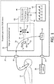
- an illustrative respiration gas monitor (RGM) device 10 is connected with a patient 12 by a suitable patient accessory, such as a nasal cannula 14 in the illustrative example, or by an airway adaptor connecting with an endotracheal tube used for mechanical ventilation, or so forth.
- the patient accessory 14 may optionally include one or more ancillary components, such as an air filter, water trap, or the like (not shown).
- respired air is drawn from the patient accessory 14 into an air inlet 16 and through target gas measurement cell 20 by a pump 22.
- respired air is then discharged via an air outlet 24 of the RGM device 10 to atmosphere or, as in the illustrative embodiment, is discharged through the air outlet 24 into a scavenging system 26 to remove an inhaled anesthetic or other inhaled medicinal agent before discharge into the atmosphere.
- the respired air generally has a composition that is different from the ambient air, for example the respired air may contain different concentrations of CO 2 , oxygen, and/or may contain added gas such as an administered anesthetic gas.
- the illustrative RGM device setup has a sidestream configuration in which respired air is drawn into the RGM device using the pump 22, and the target gas measurement cell 20 is located inside the RGM device 10.
- the sidestream configuration is suitably used for a spontaneously breathing patient, i.e. a patient who is breathing on his or her own without assistance of a mechanical ventilator.
- the target gas measurement cell is located externally from the RGM device housing, typically as a target gas measurement cell patient accessory that is inserted into the "mainstream" airway flow of the patient.
- Such a mainstream configuration may, for example, be employed in conjunction with a mechanically ventilated patient, with the target gas measurement cell patient accessory being designed to mate into an accessory receptacle of the ventilator unit, or is installed on an airway hose feeding into the ventilator.
- the target gas measurement cell 20 comprises an infrared optical absorption cell in which the target gas in the respired air drawn from the patient accessory 14 produces absorption in the infrared that is detected optically.
- CO 2 has an absorption peak at about 4.3 micron.
- other target gases may include oxygen (O 2 ), nitrous oxide (N 2 O), or an administered anesthetic gas, each of which have specific characteristic absorption lines in the infrared.
- An infrared light source 30 includes an infrared emitting element 32 that is resistively heated by a drive current I P which in some embodiments comprises an electric current pulse train. The electric current I P heats the infrared emitting element (e.g.
- broadband infrared light 34 (diagrammatically indicated by a block arrow in FIGURE 1 ) transmits through a respired air flow path 36 (diagrammatically indicated by a curve arrow in FIGURE 1 ) along which the respired air flows.
- the flow path 36 may be defined by a tube or other conduit defining a cuvette with walls made of a plastic, glass, sapphire, or other material that is substantially transparent for the infrared light 34.
- the pump 22 actively drives the flow of respired air through the flow path 36; in a mainstream configuration the flow may be driven by mechanical ventilation of the patient, and/or by active breathing of the patient.
- An optical detector 40 is configured to detect the infrared light 34.
- the optical detector 40 may be a lead selenide (PbSe) detector, a microbolometer, thermocouple, pyroelectric detector, or the like.
- an absorption line bandpass filter 42 having a passband tuned to an absorption line of the target gas is interposed between the infrared emitting element 32 and the optical detector 40.
- the absorption line bandpass filter 42 suitably has a passband that encompasses, and is preferably centered at, 4.3 micron which is a wavelength at which carbon dioxide is strongly absorbing.
- the bandpass filter is designed to have a passband that encompasses, and preferably is centered on, a strong absorption line of the other target gas.
- the absorption line bandpass filter may, for example, comprise a stack of layers on an infrared light-transmissive substrate such as sapphire, in which the layers of the stack of layers have thicknesses, refractive indices, and arrangement designed to form an interference filter with a narrow passband having the requisite center frequency (e.g. 4.3 micron for CO 2 detection).
- the illustrative embodiment of FIGURE 1 employs a separate reference line bandpass filter 44 constructed similarly to the absorption line bandpass filter 42 , but with the stack of layers tuned to a wavelength at which no component present in non-negligible quantities in the respired air exhibits strong absorption.
- the reference line bandpass filter 44 has a narrow passband that encompasses, and preferably is centered on, a frequency of 3.6 micron, although other wavelengths for which the respired air is transparent are also contemplated.
- the reference line bandpass filter 44 has a passband over which the respired air carried in the respired air flow path 36 is transparent.
- transparent it is meant that absorption by the respired air is negligibly small over the passband of the reference line bandpass filter 44 when compared with absorption by the target gas over the passband of the absorption line bandpass filter 42 for the lowest concentration or partial pressure of the target gas in the respired air that the RGM device 10 is designed to detect.
- the RGM device 10 further includes RGM device electronics 46 that provide electrical biasing of, and readout for, the optical detector 40.
- the electronics 46 optionally provide the drive current I P for the infrared light source 30 (connection not shown in FIGURE 1 ; moreover other driving configurations are contemplated such as a separate current or voltage drive power supply).
- the RGM device electronics 46 also include analog signal processing circuitry and/or digital signal processing (DSP) suitable for converting the detected signal into a gas signal 48 , e.g. a concentration or partial pressure of CO 2 in the respired air flow, and optionally for performing further processing such as detecting a breath interval and/or an end-tidal CO 2 level (etCO 2 level, relevant for capnometry embodiments).
- DSP digital signal processing
- the conversion to CO 2 level or other target gas signal can employ suitable empirical calibration - for example, in general, concentration or partial pressure of the target gas produces greater absorption and hence a reduced signal from the optical detector 40.
- the empirical calibration may take into account other factors such as flow rate or pressure, and/or the effects of gases other than the target gas (for example, oxygen and nitrous oxide are known to affect the infrared absorption characteristics due to CO 2 ), and can be suitably programmed as a look-up table, mathematical equation, non-linear op-amp circuit, or so forth.
- Another aspect of the conversion is compensating for drift in the signal output by the optical detector 40.
- drift may be due to drift in the detector 40 , and/or due to drift in the intensity of the infrared radiation 34 launched by the infrared light source 30 , and/or due to other factors such as condensate buildup on walls of the path 36 through which the respired air flows.
- a calibration is occasionally performed using the reference line bandpass filter 44 as described elsewhere herein in order to generate a reference infrared (IR) signal 50. By employing a ratio of the signal from the optical detector 40 versus the reference IR signal 50 , such drift is compensated.
- DSP digital signal processing
- ROM read only memory
- EPROM electronically programmable read-only memory
- CMOS memory flash memory
- A/D analog-to-digital
- an output component 52 is provided.
- the output component 52 is a display 52, e.g.
- the illustrative display 52 plots target gas concentration or partial pressure versus time as a trend line. Additionally or alternatively, the display may show a numerical value, e.g. of the target gas concentration at a particular time in the respiratory cycle, e.g. etCO 2 in the case of a capnometer.
- the output component may additionally or alternatively take other forms, such as being or including (possibly in addition to the display 52 ) a USB port or other data port via which the target gas data may be read out.
- the RGM device 10 may include numerous other components not illustrated in simplified diagrammatic FIGURE 1 , such as a pressure gauge and/or flow meter for monitoring the respired air flow, a keypad or other user input components, and/or so forth.
- FIGURE 1 illustrates both the absorption line bandpass filter 42 and the reference line bandpass filter 44 in the path of the infrared light 34.
- a control device is operative to switch the RGM device 10 between a monitoring state and a calibration state.
- the absorption line bandpass filter 42 is in the path of the infrared light 34 and the reference line bandpass filter 44 is not in the path of the infrared light 34.
- the monitoring state is the normal operating state, and provides for the optical detector 40 to measure the absorption of the infrared light due to the target gas (e.g. CO 2 ), since the absorption line bandpass filter 42 encompasses (and is preferably centered on) an absorption line of the target gas (e.g.
- the target gas e.g. CO 2
- the reference line bandpass filter 44 When switched to the calibration state, the reference line bandpass filter 44 is in the path of the infrared light 34 and the absorption line bandpass filter 42 is not in the path of the infrared light 34.
- This state allows for measurement of the reference infrared signal 50, since the reference line bandpass filter 44 is chosen to have a passband over which the respired air is transparent (e.g., 3.6 micron in illustrative examples herein). In this way, the reference infrared signal 50 can be measured without changing out the gas flow from respired gas to air or nitrogen.
- some illustrative embodiments of the control device for switching between the monitoring state and the calibration state are described.
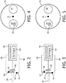
- the control device comprises a filter flipper comprising a first filter flipper 62 that mechanically moves the absorption line bandpass filter 42 into or out of the path of the infrared light 34, and a second filter flipper 64 that mechanically moves the reference line bandpass filter 44 into or out of the path of the infrared light 34.
- the two filter flippers 62, 64 are coupled together, e.g.
- control logic or electrical control circuitry 66 e.g., connected with or part of the device electronics 46 as diagrammatically indicated in FIGURES 1-3 ), so as to switch to the monitoring state by the first filter flipper 62 mechanically moving the absorption line bandpass filter 42 into the path of the infrared light 34 and the second filter flipper 64 mechanically moving the reference line bandpass filter 44 outside of the path of the infrared light 34, as shown in FIGURE 2 .
- the two filter flippers 62, 64 are similarly switchable to the calibration state by the second filter flipper 64 mechanically moving the reference line bandpass filter 44 into the path of the infrared light 34 and the first filter flipper 62 mechanically moving the absorption line bandpass filter 44 outside of the path of the infrared light.
- the switching between the monitoring state and the calibration state is fast, e.g. 0.2 sec in some contemplated embodiments.
- the RGM 10 switches from the monitoring state ( FIGURE 2 ) to the calibration state ( FIGURE 3 ), measures the reference infrared signal 50, and switches back to the monitoring state ( FIGURE 2 ) sufficiently quickly compared with a single respiration cycle (e.g. 10-20 sec for a respiration rate of 3-6 breaths per minute) so that the sampling of the target gas waveform is advantageously not significantly disturbed by the calibration.
- each bandpass filter 42, 44 is mounted on a rotating axis and the two filter flippers 62, 64 are motors that rotate the respective filters 42, 44 about those axes into and out of the path of the infrared light 34, as diagrammatically shown in FIGURES 2 and 3 .
- the filter flipper comprises a filter wheel 70 that rotates about an axis 76, and on which both the absorption line bandpass filter 42 and the reference line bandpass filter 44 are mounted.
- FIGURES 4 and 5 illustrate the monitoring state ( FIGURE 4 ) and the calibration state ( FIGURE 5 ), respectively, viewed along the optical axis of the infrared light 34.
- the filter wheel 70 is rotated about its axis 76 such that the absorption line bandpass filter 42 is rotated into the infrared light 34.
- the filter wheel 70 is rotated about its axis 76 such that the reference line bandpass filter 44 is rotated into the infrared light 34.
- the control device is connected to rotate the filter wheel 70 to implement switching between the monitoring and calibration states.
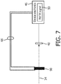
- the control device comprises an electro-optical beam steering device 80 operable at a first electric bias or at a second electric bias provided by the electrical control circuitry 66 driven by the device electronics 46.
- the optical beam steering device 80 may, for example, employ a liquid crystal device forming a switchable diffraction grating.
- Such electro-optical beam-steering devices are used, for example, in bar-code scanners to provide fast beam direction switching.
- the illustrative electro-optical beam steering device 80 steers the infrared light 34 at an angle + ⁇ to be reflected by mirrors M1 , M2 along a first optical path PI that passes through the absorption line bandpass filter 42 (and does not pass through the reference line bandpass filter 44 ) and then impinges upon the optical detector 40.
- the illustrative electro-optical beam steering device 80 steers the infrared light 34 at an angle - ⁇ to be reflected by mirrors M3, M4 along a second optical path P2 that passes through the reference line bandpass filter 44 (and does not pass through the absorption line bandpass filter 42 ) and then impinges upon the optical detector 40.
- the control device comprises an electrically tunable optical bandpass filter 90 operable at a first electric bias or a second electric bias.
- the electrically tunable optical bandpass filter 90 may, for example, comprise a liquid crystal or acousto-optic device comprising an electrically tunable interference filter that can be switched between two different passbands, e.g. 4.3 micron in the illustrative CO 2 target gas example, and 3.6 micron as the reference passband.
- the electrically tunable optical bandpass filter 90 is always disposed in the path of the infrared light 34, but can be tuned to instantiate either the absorption line bandpass filter 42 or the reference line bandpass filter 44.
- the monitoring state is implemented by tuning the electrically tunable optical bandpass filter 90 to the passband of the absorption line bandpass filter 42, whereby the electrically tunable optical bandpass filter 90 instantiates the absorption line bandpass filter 42.
- the calibration state is implemented by tuning the electrically tunable optical bandpass filter 90 to the passband of the reference line bandpass filter 44, whereby the electrically tunable optical bandpass filter 90 instantiates the reference line bandpass filter 44.
- control device 62, 64, 70, 80, 90 is not operative to divert flow of respired air through the respired air flow path 36 when operating to switch the RGM device 10 to the calibration state. Rather, the control device switches between the monitoring state and the calibration state, and indeed performs the calibration, without the need to interrupt or alter flow of respired air through the respired air flow path 36. This promotes stability of the respired air flow and eliminates transient periods when the respired air flow may not yet be stabilized after a calibration operation, and thereby improves accuracy of the RGM device 10.
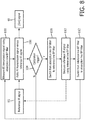
- operation of the RGM device 10 of FIGURE 1 is diagrammatically flowcharted.
- the monitoring state is depicted by operation 100 in which the infrared (IR) transmission signal is measured using the absorption line bandpass (BP) filter 42 and an operation 102 in which a ratio of the IR transmission signal and the reference IR signal 50 is computed to generate the target gas concentration or partial pressure signal 48.
- the signal processing operation 102 may optionally account other factors such as flow rate or pressure, and/or the effects of gases other than the target gas (e.g. oxygen and/or nitrous oxide which can affect the infrared absorption characteristics due to CO 2 ), and these can be suitably programmed as a look-up table, mathematical equation, non-linear op-amp circuit, or so forth.
- a decision operation 104 it is determined whether the RGM device 10 should switch from the monitoring state to the calibration state in order to update the value of the reference IR signal 50.
- the decision 104 can be based on various chosen factors. In one embodiment, the decision 104 switches to the calibration state after a fixed time interval, e.g. after every 5 minutes of monitoring. In another embodiment, the decision 104 switches when the target gas signal 48 drifts over time by more than some threshold amount, in order to ensure that the drift is not due to a change in the reference signal (e.g. due to drift of the intensity of the infrared light 34 output by the infrared light source 30, or due to drift of the optical detector 40, or due to contamination of the walls of the respired air flow path 36, or so forth). So long as the decision operation 104 does not call for updating the calibration, flow returns to the monitoring state IR transmission measurement operation 100 to continue monitoring the target gas.
- the RGM device 10 switches from the monitoring state to the calibration state by switching from the absorption line bandpass filter 42 to the reference line bandpass filter 44, e.g. using any one of the control devices described with reference to FIGURES 2-7 .
- a measurement operation 110 is performed which is analogous to the measurement operation 100 except now with the infrared light being filtered by the reference bandpass filter. This measurement 110 then provides the updated value for the reference infrared signal 50.
- the RGM device 10 switches from the calibration state back to the monitoring state by switching from the reference line bandpass filter 44 back to the absorption line bandpass filter 42.
- the calibration process sequence 108, 110, 112 involves only a rapid change-out of the bandpass filters 42, 44, e.g. by a mechanical filter flipper (e.g. illustrative embodiments of FIGURES 2-5 ), fast electro-optical beam steering (e.g. illustrative embodiment of FIGURE 6 ), or by using a tunable bandpass optical filter to instantiate the requisite filter (e.g. illustrative embodiment of FIGURE 7 ).
- the calibration can be performed rapidly so as to introduce negligible interruption in the [CO 2 ] waveform or other target gas waveform generated by the monitoring state. This in turn facilitates more frequent updating of the reference infrared signal 50 and consequently more accurate monitoring of the target gas.
Landscapes
- Health & Medical Sciences (AREA)
- Life Sciences & Earth Sciences (AREA)
- Physics & Mathematics (AREA)
- General Health & Medical Sciences (AREA)
- Engineering & Computer Science (AREA)
- Pathology (AREA)
- Chemical & Material Sciences (AREA)
- Spectroscopy & Molecular Physics (AREA)
- Veterinary Medicine (AREA)
- Public Health (AREA)
- Animal Behavior & Ethology (AREA)
- Heart & Thoracic Surgery (AREA)
- Pulmonology (AREA)
- Biomedical Technology (AREA)
- Medical Informatics (AREA)
- Biophysics (AREA)
- Physiology (AREA)
- Analytical Chemistry (AREA)
- Molecular Biology (AREA)
- Surgery (AREA)
- Immunology (AREA)
- General Physics & Mathematics (AREA)
- Biochemistry (AREA)
- Combustion & Propulsion (AREA)
- Food Science & Technology (AREA)
- Medicinal Chemistry (AREA)
- Emergency Medicine (AREA)
- Anesthesiology (AREA)
- Hematology (AREA)
- Investigating Or Analysing Materials By Optical Means (AREA)
- Measurement Of The Respiration, Hearing Ability, Form, And Blood Characteristics Of Living Organisms (AREA)
Claims (13)
- Respirationsgasüberwachungs(RGM)-Vorrichtung, umfassend:einen Atemluftströmungsweg (36), in dem Atemluft transportiert wird;eine Infrarotlichtquelle (30), die dafür eingerichtet ist, Infrarotlicht (34) durch den Atemluftströmungsweg zu schicken;einen optischen Detektor (40), der dafür eingerichtet ist, das Infrarotlicht zu erfassen, das den Atemluftströmungsweg passiert;ein Absorptionslinien-Bandpassfilter (42), das einen Durchlassbereich aufweist, der eine Absorptionslinie eines Taget-Gases umfasst;ein Bezugslinien-Bandpassfilter (44), das einen Durchlassbereich aufweist, über dem die Atemluft transparent ist;eine Steuervorrichtung (62, 64, 70, 80, 90), die betreibbar ist, um die RGM-Vorrichtung umzuschalten zwischen:einem Überwachungszustand, in dem das Absorptionslinien-Bandpassfilter im Weg des Infrarotlichts liegt und das Bezugslinien-Bandpassfilter nicht im Weg des Infrarotlichts liegt, undeinem Kalibrierungszustand, in dem das Bezugslinien-Bandpassfilter im Weg des Infrarotlichts liegt, unddas Absorptionslinien-Bandpassfilter nicht im Weg des Infrarotlichts liegt;und gekennzeichnet durcheine elektro-optische Strahllenkungsvorrichtung (80), die betreibbar ist bei:einer ersten elektrischen Vorspannung, die durch Lenken des Infrarotlichts auf einen optischen Weg (P1), der durch das Absorptionslinien-Bandpassfilter verläuft und nicht durch das Bezugslinien-Bandpassfilter verläuft, den Überwachungszustand implementiert, undeiner zweiten elektrischen Vorspannung, die durch Lenken des Infrarotlichts auf einen optischen Weg (P2), der durch das Bezugslinien-Bandpassfilter verläuft und nicht durch das Absorptionslinien-Bandpassfilter verläuft, den Kalibrierungszustand implementiert.
- RGM-Vorrichtung nach Anspruch 1 wobei die Steuervorrichtung umfasst:
einen Filterflipper (62, 64, 70), der verbunden ist zum:Umschalten auf den Überwachungszustand durch mechanisches Bewegen des Absorptionslinien-Bandpassfilters in den Weg des Infrarotlichts und mechanisches Bewegen des Bezugslinien-Bandpassfilters aus dem Weg des Infrarotlichts, undUmschalten auf den Kalibrierungszustand durch mechanisches Bewegen des Bezugslinien-Bandpassfilters in den Weg des Infrarotlichts und mechanisches Bewegen des Absorptionslinien-Bandpassfilters aus dem Weg des Infrarotlichts. - RGM-Vorrichtung nach Anspruch 2 wobei der Filterflipper ein Filterrad (70) umfasst.
- RGM-Vorrichtung nach Anspruch 1, wobei die Steuervorrichtung umfasst:
ein elektrisch abstimmbares optisches Bandpassfilter (90), das betätigbar ist bei:einer ersten elektrischen Vorspannung, die den Überwachungszustand implementiert durch Abstimmen des elektrisch abstimmbaren optischen Bandpassfilters auf den Durchlassbereich des Absorptionslinien-Bandpassfilters, wodurch das elektrisch abstimmbare optische Bandpassfilter das Absorptionslinien-Bandpassfilter (42) instanziiert; undeiner zweiten elektrischen Vorspannung, die den Kalibrierungszustand implementiert durch Abstimmen des elektrisch abstimmbaren optischen Bandpassfilters auf den Durchlassbereich des Bezugslinien-Bandpassfilters,wodurch das elektrisch abstimmbare optische Bandpassfilter das Bezugslinien-Bandpassfilter (44) instanziiert. - RGM-Vorrichtung nach einem der Ansprüche 1 bis 4, wobei das Bezugslinien-Bandpassfilter (44) einen Durchlassbereich aufweist, der 3,6 Mikrometer umfasst.
- RGM-Vorrichtung nach einem der Ansprüche 1 bis 5, wobei das Target-Gas Kohlendioxid ist und das Absorptionslinien-Bandpassfilter (44) einen Durchlassbereich aufweist, der die 4,3 Mikrometer-Absorptionslinie von Kohlendioxid umfasst.
- RGM-Vorrichtung nach einem der Ansprüche 1 bis 6, ferner umfassend:
Elektronik (46), die ausgelegt ist zum:Messen eines Bezugs-Infrarotsignals (50) unter Verwendung des optischen Detektors (40), wenn die RGM-Vorrichtung im Kalibrierungszustand ist, undMessen einer Konzentration oder eines Partialdrucks des Target-Gases in der Atemluft unter Verwendung des optischen Detektors, wenn die RGM-Vorrichtung im Überwachungszustand ist, und ferner unter Verwendung des Bezugs-Infrarotsignals. - RGM-Vorrichtung nach einem der Ansprüche 1 bis 7, wobei die Steuervorrichtung dafür ausgelegt ist, die RGM-Vorrichtung auf den Kalibrierungszustand umzuschalten, ohne einen Strom von Atemluft durch den Atemluftströmungsweg zu unterbrechen oder zu verändern.
- Verfahren zum Betreiben einer Respirationsgasüberwachungs(RGM)-Vorrichtung, wobei das Verfahren umfasst:Strömen lassen von Atemluft durch einen Atemluftströmungsweg (36);Schicken von Infrarotlicht (34) durch den Atemluftströmungsweg;Durchführen einer Überwachung eines Target-Gases, während die Atemluft durch den Atemluftströmungsweg strömt, einschließlich eines Messens eines Infrarotsendesignals, das eine Übertragung des abgeschickten Infrarotlichts durch den Atemluftströmungsweg anzeigt, während ein Absorptionslinien-Bandpassfilter (42) im Weg des Infrarotlichts angeordnet ist, und Bestimmen eines Wertes für das Target-Gas in der Atemluft aus dem Infrarotsendesignal und einem Bezugs-Infrarotsignal;Durchführen einer Kalibrierung, während die Atemluft durch den Atemluftströmungsweg strömt, einschließlich eines Messens des Bezugs-Infrarotsignals, das eine Übertragung des abgeschickten Infrarotlichts durch den Atemluftströmungsweg anzeigt, während ein Bezugslinien-Bandpassfilter (44) in dem Weg des Infrarotlichts angeordnet ist; gekennzeichnet durch:Durchführen der Überwachung des Target-Gases durch Betätigen einer elektro-optischen Strahllenkungsvorrichtung (80), um das Infrarotlicht auf einen optischen Weg (P1) zu lenken, der durch das Absorptionslinien-Bandpassfilter verläuft und nicht durch das Bezugslinien-Bandpassfilter verläuft; undDurchführen der Kalibrierung durch Betätigen der elektro-optischen Strahllenkungsvorrichtung (80), um das Infrarotlicht auf einen optischen Weg (P2) zu lenken, der durch das Bezugslinien-Bandpassfilter verläuft und nicht durch das Absorptionslinien-Bandpassfilter verläuft.
- Verfahren nach Anspruch 9, wobei:die Überwachung des Target-Gases durchgeführt wird, wenn die RGM-Vorrichtung in einem Überwachungszustand ist, in dem das Absorptionslinien-Bandpassfilter im Weg des Infrarotlichts liegt und das Bezugslinien-Bandpassfilter nicht im Weg des Infrarotlichts liegt, unddie Kalibrierung durchgeführt wird, wenn die RGM-Vorrichtung in einem Kalibrierungszustand ist, in dem das Bezugslinien-Bandpassfilter im Weg des Infrarotlichts liegt und das Absorptionslinien-Bandpassfilter nicht im Weg des Infrarotlichts liegt.
- Verfahren nach Anspruch 10, ferner umfassend:
Bewegen des Absorptionslinien-Bandpassfilters und des Bezugslinien-Bandpassfilters unter Verwendung des Filterflippers (62, 64, 70), um zwischen einem Überwachungszustand und dem Kalibrierungszustand umzuschalten. - Verfahren nach Anspruch 9, wobei:die Überwachung des Target-Gases durchgeführt wird, während die RGM-Vorrichtung in einem Überwachungszustand ist, in dem ein elektrisch abstimmbares Bandpassfilter (90) das Absorptionslinien-Bandpassfilter (42) instanziiert, weil es auf einen Durchlassbereich abgestimmt wird, der eine Absorptionslinie eines Target-Gases umfasst; unddie Kalibrierung durchgeführt wird, während die RGM-Vorrichtung in einem Kalibrierungszustand ist, in dem das elektrisch abstimmbare Bandpassfilter das Bezugslinien-Bandpassfilter (44) instanziiert, weil es auf einen Durchlassbereich abgestimmt wird, über dem die Atemluft transparent ist.
- Verfahren nach einem der Ansprüche 9 bis 12, wobei das Absorptionslinien-Bandpassfilter (42) einen Durchlassbereich aufweist, der eine Absorptionslinie eines Target-Gases umfasst, und das Bezugslinien-Bandpassfilter (44) einen Durchlassbereich aufweist, über dem die Atemluft transparent ist.
Applications Claiming Priority (2)
| Application Number | Priority Date | Filing Date | Title |
|---|---|---|---|
| US201762473514P | 2017-03-20 | 2017-03-20 | |
| PCT/EP2018/057077 WO2018172381A1 (en) | 2017-03-20 | 2018-03-20 | Respiration gas monitor with automated and nonobtrusive filter calibration |
Publications (2)
| Publication Number | Publication Date |
|---|---|
| EP3602008A1 EP3602008A1 (de) | 2020-02-05 |
| EP3602008B1 true EP3602008B1 (de) | 2021-12-29 |
Family
ID=62017290
Family Applications (1)
| Application Number | Title | Priority Date | Filing Date |
|---|---|---|---|
| EP18718578.0A Not-in-force EP3602008B1 (de) | 2017-03-20 | 2018-03-20 | Atemgasmonitor mit automatisierter und unauffälliger filterkalibrierung |
Country Status (5)
| Country | Link |
|---|---|
| US (1) | US20200018735A1 (de) |
| EP (1) | EP3602008B1 (de) |
| JP (1) | JP2020516336A (de) |
| CN (1) | CN110462378A (de) |
| WO (1) | WO2018172381A1 (de) |
Families Citing this family (1)
| Publication number | Priority date | Publication date | Assignee | Title |
|---|---|---|---|---|
| CN119386331A (zh) * | 2024-10-31 | 2025-02-07 | 四川省肿瘤医院 | 一种用于呼吸机的废气监测及收集处理系统 |
Family Cites Families (10)
| Publication number | Priority date | Publication date | Assignee | Title |
|---|---|---|---|---|
| US3539804A (en) * | 1968-12-23 | 1970-11-10 | Us Army | Fluid analysis by infrared absorption |
| DE2438294B2 (de) * | 1974-08-09 | 1977-05-18 | Licentia Patent-Verwaltungs-Gmbh, 6000 Frankfurt | Infrarotgasanalysator |
| JPS5723843A (en) * | 1980-07-21 | 1982-02-08 | Nippon Koden Corp | Measuring apparatus of concentration of respiratory gas |
| US5027178A (en) * | 1989-08-03 | 1991-06-25 | Northern Telecom Limited | Electrically tunable interference filters and methods for their use |
| JP4457455B2 (ja) * | 2000-02-18 | 2010-04-28 | 横河電機株式会社 | ファブリペローフィルタ及び赤外線ガス分析計 |
| CN100494983C (zh) * | 2005-08-12 | 2009-06-03 | 深圳迈瑞生物医疗电子股份有限公司 | 利用红外光吸收特性自动校准和测量气体浓度的方法和装置 |
| ATE546725T1 (de) * | 2007-11-09 | 2012-03-15 | Phasein Ab | Gasmesssystem |
| CN201740945U (zh) * | 2010-03-10 | 2011-02-09 | 武汉光迅科技股份有限公司 | 使用温控电路来提高性能的液晶型波长选择光开关 |
| GB2530095B (en) * | 2014-09-15 | 2017-07-12 | Schlumberger Holdings | Mid-infrared sensor |
| JP6574110B2 (ja) * | 2015-06-26 | 2019-09-11 | 旭化成エレクトロニクス株式会社 | ガスセンサ回路、ガスセンサ装置及びガス濃度検知方法 |
-
2018
- 2018-03-20 US US16/495,583 patent/US20200018735A1/en not_active Abandoned
- 2018-03-20 JP JP2019551660A patent/JP2020516336A/ja active Pending
- 2018-03-20 EP EP18718578.0A patent/EP3602008B1/de not_active Not-in-force
- 2018-03-20 WO PCT/EP2018/057077 patent/WO2018172381A1/en not_active Ceased
- 2018-03-20 CN CN201880019845.1A patent/CN110462378A/zh active Pending
Also Published As
| Publication number | Publication date |
|---|---|
| CN110462378A (zh) | 2019-11-15 |
| US20200018735A1 (en) | 2020-01-16 |
| JP2020516336A (ja) | 2020-06-11 |
| WO2018172381A1 (en) | 2018-09-27 |
| EP3602008A1 (de) | 2020-02-05 |
Similar Documents
| Publication | Publication Date | Title |
|---|---|---|
| EP2444791B1 (de) | Gasanalysegerät zur Messung von mindestens zwei Bestandteilen eines Gases | |
| FI80202C (fi) | Foerfarande och anordning foer bestaemning av deltryck av koldioxid i pulsblod av en narkotiserad patient. | |
| CN102890069B (zh) | 用于测量呼吸气体的氧气浓度的气体传感器、分析器和方法 | |
| US20110295140A1 (en) | Method and Apparatus for Measuring Trace Levels of CO in Human Breath Using Cavity Enhanced, Mid-Infared Absorption Spectroscopy | |
| US7235054B2 (en) | Measuring head for a gas analyser | |
| US6888101B2 (en) | Heater for optical gas sensors, gas sensors including the heater, and methods | |
| CN101248336A (zh) | 气体测量系统 | |
| JPS6044614B2 (ja) | ガス分析器のドリフト補正装置 | |
| US6534769B1 (en) | Low cost main stream gas analyzer system | |
| JPH09510550A (ja) | 呼吸ガス分析器 | |
| JPH06100542B2 (ja) | ガス分析装置 | |
| CN101589302A (zh) | 气体测量系统 | |
| JP2007285842A5 (de) | ||
| JPH10111236A (ja) | 炭酸ガス濃度測定装置 | |
| EP3602008B1 (de) | Atemgasmonitor mit automatisierter und unauffälliger filterkalibrierung | |
| US7301125B2 (en) | Heater for optical gas sensor | |
| EP0762107A1 (de) | Infrarot-Gasanalysator und Feuchtesensor | |
| EP3568071B1 (de) | Kapnografie mit detektor und integriertem bandpassfilter | |
| US5965887A (en) | Method and apparatus for monitoring maintenance of calibration condition in respiratory gas spectrometer | |
| WO2018172203A1 (en) | Respiration gas monitor with automated resistance calibration | |
| US5608212A (en) | Method for calibrating the zero point in a gas analyzer | |
| EP1070956A1 (de) | Verfahren und Vorrichtung zur Überwachung der Eichung in einem Gasspektrometer für Atemgase | |
| JPH0989765A (ja) | 赤外線ガス分析器 | |
| JP4727444B2 (ja) | ガス分析装置及び半導体製造装置 | |
| JP3488971B2 (ja) | 炭酸ガス濃度測定装置 |
Legal Events
| Date | Code | Title | Description |
|---|---|---|---|
| STAA | Information on the status of an ep patent application or granted ep patent |
Free format text: STATUS: UNKNOWN |
|
| STAA | Information on the status of an ep patent application or granted ep patent |
Free format text: STATUS: THE INTERNATIONAL PUBLICATION HAS BEEN MADE |
|
| PUAI | Public reference made under article 153(3) epc to a published international application that has entered the european phase |
Free format text: ORIGINAL CODE: 0009012 |
|
| STAA | Information on the status of an ep patent application or granted ep patent |
Free format text: STATUS: REQUEST FOR EXAMINATION WAS MADE |
|
| 17P | Request for examination filed |
Effective date: 20191021 |
|
| AK | Designated contracting states |
Kind code of ref document: A1 Designated state(s): AL AT BE BG CH CY CZ DE DK EE ES FI FR GB GR HR HU IE IS IT LI LT LU LV MC MK MT NL NO PL PT RO RS SE SI SK SM TR |
|
| AX | Request for extension of the european patent |
Extension state: BA ME |
|
| RAP1 | Party data changed (applicant data changed or rights of an application transferred) |
Owner name: KONINKLIJKE PHILIPS N.V. |
|
| DAV | Request for validation of the european patent (deleted) | ||
| DAX | Request for extension of the european patent (deleted) | ||
| GRAP | Despatch of communication of intention to grant a patent |
Free format text: ORIGINAL CODE: EPIDOSNIGR1 |
|
| STAA | Information on the status of an ep patent application or granted ep patent |
Free format text: STATUS: GRANT OF PATENT IS INTENDED |
|
| INTG | Intention to grant announced |
Effective date: 20210729 |
|
| GRAS | Grant fee paid |
Free format text: ORIGINAL CODE: EPIDOSNIGR3 |
|
| GRAA | (expected) grant |
Free format text: ORIGINAL CODE: 0009210 |
|
| STAA | Information on the status of an ep patent application or granted ep patent |
Free format text: STATUS: THE PATENT HAS BEEN GRANTED |
|
| AK | Designated contracting states |
Kind code of ref document: B1 Designated state(s): AL AT BE BG CH CY CZ DE DK EE ES FI FR GB GR HR HU IE IS IT LI LT LU LV MC MK MT NL NO PL PT RO RS SE SI SK SM TR |
|
| REG | Reference to a national code |
Ref country code: GB Ref legal event code: FG4D |
|
| REG | Reference to a national code |
Ref country code: CH Ref legal event code: EP |
|
| REG | Reference to a national code |
Ref country code: AT Ref legal event code: REF Ref document number: 1459039 Country of ref document: AT Kind code of ref document: T Effective date: 20220115 |
|
| REG | Reference to a national code |
Ref country code: IE Ref legal event code: FG4D |
|
| REG | Reference to a national code |
Ref country code: DE Ref legal event code: R096 Ref document number: 602018028776 Country of ref document: DE |
|
| REG | Reference to a national code |
Ref country code: LT Ref legal event code: MG9D |
|
| PG25 | Lapsed in a contracting state [announced via postgrant information from national office to epo] |
Ref country code: RS Free format text: LAPSE BECAUSE OF FAILURE TO SUBMIT A TRANSLATION OF THE DESCRIPTION OR TO PAY THE FEE WITHIN THE PRESCRIBED TIME-LIMIT Effective date: 20211229 Ref country code: LT Free format text: LAPSE BECAUSE OF FAILURE TO SUBMIT A TRANSLATION OF THE DESCRIPTION OR TO PAY THE FEE WITHIN THE PRESCRIBED TIME-LIMIT Effective date: 20211229 Ref country code: FI Free format text: LAPSE BECAUSE OF FAILURE TO SUBMIT A TRANSLATION OF THE DESCRIPTION OR TO PAY THE FEE WITHIN THE PRESCRIBED TIME-LIMIT Effective date: 20211229 Ref country code: BG Free format text: LAPSE BECAUSE OF FAILURE TO SUBMIT A TRANSLATION OF THE DESCRIPTION OR TO PAY THE FEE WITHIN THE PRESCRIBED TIME-LIMIT Effective date: 20220329 |
|
| REG | Reference to a national code |
Ref country code: NL Ref legal event code: MP Effective date: 20211229 |
|
| REG | Reference to a national code |
Ref country code: AT Ref legal event code: MK05 Ref document number: 1459039 Country of ref document: AT Kind code of ref document: T Effective date: 20211229 |
|
| PG25 | Lapsed in a contracting state [announced via postgrant information from national office to epo] |
Ref country code: SE Free format text: LAPSE BECAUSE OF FAILURE TO SUBMIT A TRANSLATION OF THE DESCRIPTION OR TO PAY THE FEE WITHIN THE PRESCRIBED TIME-LIMIT Effective date: 20211229 Ref country code: NO Free format text: LAPSE BECAUSE OF FAILURE TO SUBMIT A TRANSLATION OF THE DESCRIPTION OR TO PAY THE FEE WITHIN THE PRESCRIBED TIME-LIMIT Effective date: 20220329 Ref country code: LV Free format text: LAPSE BECAUSE OF FAILURE TO SUBMIT A TRANSLATION OF THE DESCRIPTION OR TO PAY THE FEE WITHIN THE PRESCRIBED TIME-LIMIT Effective date: 20211229 Ref country code: HR Free format text: LAPSE BECAUSE OF FAILURE TO SUBMIT A TRANSLATION OF THE DESCRIPTION OR TO PAY THE FEE WITHIN THE PRESCRIBED TIME-LIMIT Effective date: 20211229 Ref country code: GR Free format text: LAPSE BECAUSE OF FAILURE TO SUBMIT A TRANSLATION OF THE DESCRIPTION OR TO PAY THE FEE WITHIN THE PRESCRIBED TIME-LIMIT Effective date: 20220330 |
|
| PG25 | Lapsed in a contracting state [announced via postgrant information from national office to epo] |
Ref country code: NL Free format text: LAPSE BECAUSE OF FAILURE TO SUBMIT A TRANSLATION OF THE DESCRIPTION OR TO PAY THE FEE WITHIN THE PRESCRIBED TIME-LIMIT Effective date: 20211229 |
|
| PG25 | Lapsed in a contracting state [announced via postgrant information from national office to epo] |
Ref country code: SM Free format text: LAPSE BECAUSE OF FAILURE TO SUBMIT A TRANSLATION OF THE DESCRIPTION OR TO PAY THE FEE WITHIN THE PRESCRIBED TIME-LIMIT Effective date: 20211229 Ref country code: SK Free format text: LAPSE BECAUSE OF FAILURE TO SUBMIT A TRANSLATION OF THE DESCRIPTION OR TO PAY THE FEE WITHIN THE PRESCRIBED TIME-LIMIT Effective date: 20211229 Ref country code: RO Free format text: LAPSE BECAUSE OF FAILURE TO SUBMIT A TRANSLATION OF THE DESCRIPTION OR TO PAY THE FEE WITHIN THE PRESCRIBED TIME-LIMIT Effective date: 20211229 Ref country code: PT Free format text: LAPSE BECAUSE OF FAILURE TO SUBMIT A TRANSLATION OF THE DESCRIPTION OR TO PAY THE FEE WITHIN THE PRESCRIBED TIME-LIMIT Effective date: 20220429 Ref country code: ES Free format text: LAPSE BECAUSE OF FAILURE TO SUBMIT A TRANSLATION OF THE DESCRIPTION OR TO PAY THE FEE WITHIN THE PRESCRIBED TIME-LIMIT Effective date: 20211229 Ref country code: EE Free format text: LAPSE BECAUSE OF FAILURE TO SUBMIT A TRANSLATION OF THE DESCRIPTION OR TO PAY THE FEE WITHIN THE PRESCRIBED TIME-LIMIT Effective date: 20211229 Ref country code: CZ Free format text: LAPSE BECAUSE OF FAILURE TO SUBMIT A TRANSLATION OF THE DESCRIPTION OR TO PAY THE FEE WITHIN THE PRESCRIBED TIME-LIMIT Effective date: 20211229 |
|
| PG25 | Lapsed in a contracting state [announced via postgrant information from national office to epo] |
Ref country code: PL Free format text: LAPSE BECAUSE OF FAILURE TO SUBMIT A TRANSLATION OF THE DESCRIPTION OR TO PAY THE FEE WITHIN THE PRESCRIBED TIME-LIMIT Effective date: 20211229 Ref country code: AT Free format text: LAPSE BECAUSE OF FAILURE TO SUBMIT A TRANSLATION OF THE DESCRIPTION OR TO PAY THE FEE WITHIN THE PRESCRIBED TIME-LIMIT Effective date: 20211229 |
|
| PG25 | Lapsed in a contracting state [announced via postgrant information from national office to epo] |
Ref country code: IS Free format text: LAPSE BECAUSE OF FAILURE TO SUBMIT A TRANSLATION OF THE DESCRIPTION OR TO PAY THE FEE WITHIN THE PRESCRIBED TIME-LIMIT Effective date: 20220429 |
|
| REG | Reference to a national code |
Ref country code: DE Ref legal event code: R097 Ref document number: 602018028776 Country of ref document: DE |
|
| PG25 | Lapsed in a contracting state [announced via postgrant information from national office to epo] |
Ref country code: MC Free format text: LAPSE BECAUSE OF FAILURE TO SUBMIT A TRANSLATION OF THE DESCRIPTION OR TO PAY THE FEE WITHIN THE PRESCRIBED TIME-LIMIT Effective date: 20211229 Ref country code: DK Free format text: LAPSE BECAUSE OF FAILURE TO SUBMIT A TRANSLATION OF THE DESCRIPTION OR TO PAY THE FEE WITHIN THE PRESCRIBED TIME-LIMIT Effective date: 20211229 Ref country code: AL Free format text: LAPSE BECAUSE OF FAILURE TO SUBMIT A TRANSLATION OF THE DESCRIPTION OR TO PAY THE FEE WITHIN THE PRESCRIBED TIME-LIMIT Effective date: 20211229 |
|
| REG | Reference to a national code |
Ref country code: CH Ref legal event code: PL |
|
| PLBE | No opposition filed within time limit |
Free format text: ORIGINAL CODE: 0009261 |
|
| STAA | Information on the status of an ep patent application or granted ep patent |
Free format text: STATUS: NO OPPOSITION FILED WITHIN TIME LIMIT |
|
| GBPC | Gb: european patent ceased through non-payment of renewal fee |
Effective date: 20220329 |
|
| 26N | No opposition filed |
Effective date: 20220930 |
|
| REG | Reference to a national code |
Ref country code: BE Ref legal event code: MM Effective date: 20220331 |
|
| PG25 | Lapsed in a contracting state [announced via postgrant information from national office to epo] |
Ref country code: LU Free format text: LAPSE BECAUSE OF NON-PAYMENT OF DUE FEES Effective date: 20220320 Ref country code: LI Free format text: LAPSE BECAUSE OF NON-PAYMENT OF DUE FEES Effective date: 20220331 Ref country code: IE Free format text: LAPSE BECAUSE OF NON-PAYMENT OF DUE FEES Effective date: 20220320 Ref country code: GB Free format text: LAPSE BECAUSE OF NON-PAYMENT OF DUE FEES Effective date: 20220329 Ref country code: FR Free format text: LAPSE BECAUSE OF NON-PAYMENT OF DUE FEES Effective date: 20220331 Ref country code: CH Free format text: LAPSE BECAUSE OF NON-PAYMENT OF DUE FEES Effective date: 20220331 |
|
| PG25 | Lapsed in a contracting state [announced via postgrant information from national office to epo] |
Ref country code: SI Free format text: LAPSE BECAUSE OF FAILURE TO SUBMIT A TRANSLATION OF THE DESCRIPTION OR TO PAY THE FEE WITHIN THE PRESCRIBED TIME-LIMIT Effective date: 20211229 Ref country code: BE Free format text: LAPSE BECAUSE OF NON-PAYMENT OF DUE FEES Effective date: 20220331 |
|
| PG25 | Lapsed in a contracting state [announced via postgrant information from national office to epo] |
Ref country code: IT Free format text: LAPSE BECAUSE OF FAILURE TO SUBMIT A TRANSLATION OF THE DESCRIPTION OR TO PAY THE FEE WITHIN THE PRESCRIBED TIME-LIMIT Effective date: 20211229 |
|
| PG25 | Lapsed in a contracting state [announced via postgrant information from national office to epo] |
Ref country code: MK Free format text: LAPSE BECAUSE OF FAILURE TO SUBMIT A TRANSLATION OF THE DESCRIPTION OR TO PAY THE FEE WITHIN THE PRESCRIBED TIME-LIMIT Effective date: 20211229 Ref country code: CY Free format text: LAPSE BECAUSE OF FAILURE TO SUBMIT A TRANSLATION OF THE DESCRIPTION OR TO PAY THE FEE WITHIN THE PRESCRIBED TIME-LIMIT Effective date: 20211229 |
|
| PGFP | Annual fee paid to national office [announced via postgrant information from national office to epo] |
Ref country code: DE Payment date: 20240328 Year of fee payment: 7 |
|
| PG25 | Lapsed in a contracting state [announced via postgrant information from national office to epo] |
Ref country code: HU Free format text: LAPSE BECAUSE OF FAILURE TO SUBMIT A TRANSLATION OF THE DESCRIPTION OR TO PAY THE FEE WITHIN THE PRESCRIBED TIME-LIMIT; INVALID AB INITIO Effective date: 20180320 |
|
| PG25 | Lapsed in a contracting state [announced via postgrant information from national office to epo] |
Ref country code: TR Free format text: LAPSE BECAUSE OF FAILURE TO SUBMIT A TRANSLATION OF THE DESCRIPTION OR TO PAY THE FEE WITHIN THE PRESCRIBED TIME-LIMIT Effective date: 20211229 |
|
| PG25 | Lapsed in a contracting state [announced via postgrant information from national office to epo] |
Ref country code: MT Free format text: LAPSE BECAUSE OF FAILURE TO SUBMIT A TRANSLATION OF THE DESCRIPTION OR TO PAY THE FEE WITHIN THE PRESCRIBED TIME-LIMIT Effective date: 20211229 |
|
| REG | Reference to a national code |
Ref country code: DE Ref legal event code: R119 Ref document number: 602018028776 Country of ref document: DE |
|
| PG25 | Lapsed in a contracting state [announced via postgrant information from national office to epo] |
Ref country code: DE Free format text: LAPSE BECAUSE OF NON-PAYMENT OF DUE FEES Effective date: 20251001 |