EP3602877B1 - Appareil et procédés de télécommunications sans fil - Google Patents
Appareil et procédés de télécommunications sans fil Download PDFInfo
- Publication number
- EP3602877B1 EP3602877B1 EP18711131.5A EP18711131A EP3602877B1 EP 3602877 B1 EP3602877 B1 EP 3602877B1 EP 18711131 A EP18711131 A EP 18711131A EP 3602877 B1 EP3602877 B1 EP 3602877B1
- Authority
- EP
- European Patent Office
- Prior art keywords
- data
- block
- transmission resources
- transmission
- transmissions
- Prior art date
- Legal status (The legal status is an assumption and is not a legal conclusion. Google has not performed a legal analysis and makes no representation as to the accuracy of the status listed.)
- Active
Links
Images






Classifications
-
- H—ELECTRICITY
- H04—ELECTRIC COMMUNICATION TECHNIQUE
- H04L—TRANSMISSION OF DIGITAL INFORMATION, e.g. TELEGRAPHIC COMMUNICATION
- H04L1/00—Arrangements for detecting or preventing errors in the information received
- H04L1/08—Arrangements for detecting or preventing errors in the information received by repeating transmission, e.g. Verdan system
-
- H—ELECTRICITY
- H04—ELECTRIC COMMUNICATION TECHNIQUE
- H04B—TRANSMISSION
- H04B7/00—Radio transmission systems, i.e. using radiation field
- H04B7/02—Diversity systems; Multi-antenna system, i.e. transmission or reception using multiple antennas
- H04B7/04—Diversity systems; Multi-antenna system, i.e. transmission or reception using multiple antennas using two or more spaced independent antennas
- H04B7/0413—MIMO systems
-
- H—ELECTRICITY
- H04—ELECTRIC COMMUNICATION TECHNIQUE
- H04W—WIRELESS COMMUNICATION NETWORKS
- H04W72/00—Local resource management
- H04W72/04—Wireless resource allocation
- H04W72/044—Wireless resource allocation based on the type of the allocated resource
Definitions
- the present disclosure relates to wireless telecommunications apparatus and methods.
- Third and fourth generation mobile telecommunication systems such as those based on the 3GPP defined UMTS and Long Term Evolution (LTE) architecture, are able to support more sophisticated services than simple voice and messaging services offered by previous generations of mobile telecommunication systems.
- LTE Long Term Evolution
- a user is able to enjoy high data rate applications such as mobile video streaming and mobile video conferencing that would previously only have been available via a fixed line data connection.
- the demand to deploy such networks is therefore strong and the coverage area of these networks, i.e. geographic locations where access to the networks is possible, is expected to increase rapidly.
- Future wireless communications networks will be expected to efficiently support communications with a wider range of devices associated with a wider range of data traffic profiles and types than current systems are optimised to support. For example it is expected future wireless communications networks will be expected to efficiently support communications with devices including reduced complexity devices, machine type communication devices, high resolution video displays, virtual reality headsets and so on.
- devices including reduced complexity devices, machine type communication devices, high resolution video displays, virtual reality headsets and so on.
- Some of these different types of devices may be deployed in very large numbers, for example low complexity devices for supporting the "The Internet of Things", and may typically be associated with the transmissions of relatively small amounts of data with relatively high latency tolerance.
- Other types of device for example supporting high-definition video streaming, may be associated with transmissions of relatively large amounts of data with relatively low latency tolerance.
- Yet other types of device may be characterised by data that should be transmitted through a network with low latency and high reliability.
- a single device type might also be associated with different traffic profiles / characteristics depending on the application(s) it is running. For example, different consideration may apply for efficiently supporting data exchange with a smartphone when it is running a video streaming application (high downlink data) as compared to when it is running an Internet browsing application (sporadic uplink and downlink data) or being used for voice communications by an emergency responder in an emergency scenario.
- Example use case currently considered to be of interest for next generation wireless communication systems include so-called Enhanced Mobile Broadband (eMBB) and Ultra Reliable and Low Latency Communications (URLLC). See, for example, the 3GPP document RP-160671, "New SID Proposal: Study on New Radio Access Technology," NTT DOCOMO, RAN#71 [1 ].
- eMBB Enhanced Mobile Broadband
- URLLC Ultra Reliable and Low Latency Communications
- eMBB services may be typically characterised as high capacity services, for example, supporting up to 20 Gb / s.
- eMBB services may be expected to use a long scheduling time so as to minimise resource allocation signalling overhead, where scheduling time refers to the time available for data transmission between resource allocations.
- scheduling time refers to the time available for data transmission between resource allocations.
- eMBB services are expected to rely on relatively infrequent allocation messages that allocate radio resources for higher layer data for a relatively long period of time between allocation messages (i.e. such that radio resources are allocated in relatively large blocks).
- URLLC services are low latency services, for example aiming to transmit relatively small amounts of data through the radio network with a 1 ms packet transit time (i.e. so that each piece of URLLC data needs to be scheduled and transmitted across the physical layer in a time that is shorter than 1 ms) with high reliability, for example with a 99.999% reliability target.
- the inventors have recognized the desire to support increasingly lower latency and higher reliability data transfer in wireless telecommunications systems, and to do so in a manner that makes efficient use of available transmission resources, gives rise to new challenges to be addressed to help optimise the operation of wireless telecommunications systems.
- US2005265282 describes a method which adaptively sends control messages and a predetermined number of fast repeats of the control messages on the traffic channel of a mobile communication system. For a control message which has already been lost, the system sends the control message again with a first number of fast repeats if the traffic channel is operating at a full rate; and the system sends the control message with a second number of fast repeats if the traffic channel is operating at a subrate. The number of fast repeats is selectable. If the control message has not been previously sent and the traffic channel is operating at a subrate, the system will send the control message with a third number of fast repeats.
- US6400755 describes rate assignment circuitry which detects when a data transmission begins and originally assigns an Orthogonal Variable Spreading Factor code corresponding to low data rate. Over time, a base station controller determines when an OVSF code and/or a repetition rate should be changed (i.e., data rate increased or decreased). The OVSF code and/or the repetition rate is changed in order to gradually increase the data rate, up to a maximum allowable data rate. Once data transmission ceases for a period of time the OVSF code and/or the repetition rate is changed in order to gradually decrease the data rate, down to a lowest allowable data rate.
- Packet duplication in NR (R2-1700423 ), is a 3GPP technical document describing details of packet duplication in new radio (NR). The document proposes that if packet duplication is introduced in NR, the MAC performs packet duplication, packet duplication can be applied per logical channel, packet duplication can be applied for a MAC control element, and the duplication number is configurable.
- US2005229038 describes a transmitter which is said to redundantly transmit data in an available band range when transmitting data.
- a receiver discards redundancy and receives the data.
- the receiver also redundantly transmits ack in an available band range. Since data is redundantly transmitted/received, there is said to be a high possibility that data may reach the opposite party normally even if one of the duplicate data is lost. Accordingly, it is said that highspeed communication can be realized. Since time no data flows through a communication route is reduced, network resources are said to be effectively utilized.
- UL Grant-free transmission (R1-1701665 ), is a 3GPP technical document describing a grant-free scheme for supporting transmissions for ultra reliable low latency communication.
- the document proposes that grant-free transmission resource and parameters can be configured at least by high layer signalling, the number of grant-free repetitions should be semi-statically adjusted, and that UE regrouping among different resource units over different transmission slots should be considered as one hopping mechanism option for UL grant-free transmission.
- the present disclosure can help address or mitigate at least some of the issues discussed above.
- Figure 1 provides a schematic diagram illustrating some basic functionality of a mobile telecommunications network / system 100 operating generally in accordance with LTE principles, but which may also support other radio access technologies, and which may implement embodiments of the disclosure as described herein.
- Various elements of Figure 1 and certain aspects of their respective modes of operation are well-known and defined in the relevant standards administered by the 3GPP (RTM) body, and also described in many books on the subject, for example, Holma H. and Toskala A [2].
- the network 100 includes a plurality of base stations 101 connected to a core network 102.
- Each base station provides a coverage area 103 (i.e. a cell) within which data can be communicated to and from terminal devices 104.
- Data is transmitted from base stations 101 to terminal devices 104 within their respective coverage areas 103 via a radio downlink.
- Data is transmitted from terminal devices 104 to the base stations 101 via a radio uplink.
- the core network 102 routes data to and from the terminal devices 104 via the respective base stations 101 and provides functions such as authentication, mobility management, charging and so on.
- Terminal devices may also be referred to as mobile stations, user equipment (UE), user terminal, mobile radio, communications device, and so forth.
- Base stations which are an example of network infrastructure equipment, may also be referred to as transceiver stations / nodeBs / e-nodeBs, g-nodeBs and so forth.
- transceiver stations / nodeBs / e-nodeBs, g-nodeBs and so forth.
- different terminology is often associated with different generations of wireless telecommunications systems for elements providing broadly comparable functionality.
- certain embodiments of the disclosure may be equally implemented in different generations of wireless telecommunications systems, and for simplicity particular terminology may be used regardless of the underlying network architecture. That is to say, the use of a specific term in relation to certain example implementations is not intended to indicate these implementations are limited to a certain generation of network that may be most associated with that particular terminology.
- FIG. 2 is a schematic diagram illustrating a network architecture for a new RAT wireless mobile telecommunications network / system 300 based on previously proposed approaches which may also be adapted to provide functionality in accordance with embodiments of the disclosure described herein.
- the new RAT network 300 represented in Figure 2 comprises a first communication cell 301 and a second communication cell 302.
- Each communication cell 301, 302 comprises a controlling node (centralised unit) 321, 322 in communication with a core network component 310 over a respective wired or wireless link 351, 352.
- the respective controlling nodes 321, 322 are also each in communication with a plurality of distributed units (radio access nodes / remote transmission and reception points (TRPs)) 311, 312 in their respective cells.
- TRPs remote transmission and reception points
- the distributed units 311, 312 are responsible for providing the radio access interface for terminal devices connected to the network.
- Each distributed unit 311, 312 has a coverage area (radio access footprint) 341, 342 which together define the coverage of the respective communication cells 301, 302.
- the core network component 310 of the new RAT telecommunications system represented in Figure 2 may be broadly considered to correspond with the core network 102 represented in Figure 1
- the respective controlling nodes 321, 322 and their associated distributed units / TRPs 311, 312 may be broadly considered to provide functionality corresponding to base stations of Figure 1
- the term network infrastructure equipment / element may be used to encompass these elements and more conventional base station type elements of wireless telecommunications systems.
- the responsibility for scheduling transmissions which are scheduled on the radio interface between the respective distributed units and the terminal devices may lie with the controlling node / centralised unit and / or the distributed units / TRPs.
- a terminal device 400 is represented in Figure 2 within the coverage area of the first communication cell 301. This terminal device 400 may thus exchange signalling with the first controlling node 321 in the first communication cell via one of the distributed units 311 associated with the first communication cell 301. In some cases communications for a given terminal device are routed through only one of the distributed units, but it will be appreciated in some other implementations communications associated with a given terminal device may be routed through more than one distributed unit, for example in a soft handover scenario and other scenarios.
- the particular distributed unit(s) through which a terminal device is currently connected through to the associated controlling node may be referred to as active distributed units for the terminal device.
- the active subset of distributed units for a terminal device may comprise one or more than one distributed unit (TRP).
- the controlling node 321 is responsible for determining which of the distributed units 311 spanning the first communication cell 301 is responsible for radio communications with the terminal device 400 at any given time (i.e. which of the distributed units are currently active distributed units for the terminal device). Typically this will be based on measurements of radio channel conditions between the terminal device 400 and respective ones of the distributed units 311. In this regard, it will be appreciated the subset of the distributed units in a cell which are currently active for a terminal device will depend, at least in part, on the location of the terminal device within the cell (since this contributes significantly to the radio channel conditions that exist between the terminal device and respective ones of the distributed units).
- two communication cells 301, 302 and one terminal device 400 are shown for simplicity, but it will of course be appreciated that in practice the system may comprise a larger number of communication cells (each supported by a respective controlling node and plurality of distributed units) serving a larger number of terminal devices.
- Figure 2 represents merely one example of a proposed architecture for a new RAT telecommunications system in which approaches in accordance with the principles described herein may be adopted, and the functionality disclosed herein may also be applied in respect of wireless telecommunications systems having different architectures. That is to say, the specific wireless telecommunications architecture for a wireless telecommunications system adapted to implement functionality in accordance with the principles described herein is not significant to the principles underlying the described approaches.
- the network infrastructure equipment may comprise a base station, such as an LTE-type base station 101 as shown in Figure 1 which is adapted to provide functionality in accordance with the principles described herein, and in other examples the network infrastructure equipment may comprise a control unit / controlling node 321, 322 and / or a TRP 311, 312 of the kind shown in Figure 2 which is adapted to provide functionality in accordance with the principles described herein.
- a base station such as an LTE-type base station 101 as shown in Figure 1 which is adapted to provide functionality in accordance with the principles described herein
- the network infrastructure equipment may comprise a control unit / controlling node 321, 322 and / or a TRP 311, 312 of the kind shown in Figure 2 which is adapted to provide functionality in accordance with the principles described herein.
- mobile communications networks such as the network 100 shown in Figure 1 and the network 300 shown in Figure 2 may support certain services for which low latency and high reliability are primary concerns (e.g. URLLC).
- URLLC low latency and high reliability
- Such services may be generally referred to herein as URLLC services, but it will be appreciated the principles and approaches described herein are not only applicable to specific URLLC services as currently proposed, but are generally applicable, in particular, but not exclusively, to services having the same characteristics as URLLC services in respect of a desire for low latency and high reliability.
- URLLC-type services will be associated with relatively short transmission time intervals (to help reduce latency) and make use of repeat transmissions (to help increase reliability).
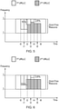
- Figure 3 schematically represents how radio transmission resources in a time and frequency radio resource grid may be used for transmitting a block of data associated with a URLLC service in the uplink (i.e. from a terminal device to a base station) in a wireless telecommunications system in accordance with certain embodiments of the disclosure.
- This figure schematically represent an array / grid of radio resources arranged in time (horizontal axis) and frequency (vertical axis) that may be used to support the URLLC service.
- the wireless telecommunications system is configured so the terminal device may autonomously select radio resources from within a frequency range f1 to f2 to use for uplink URLLC transmissions on a grant-free basis (i.e.
- the terminal device may also receive allocation signalling from a base station, for example in a downlink control information, DCI, message to identify radio resources for URLLC transmissions for the terminal device. That is to say, URLLC transmissions associated with terminal devices operating in the system may be made on resources which are autonomously selected by the terminal device from a pool of available resources (grant-free resources) or allocated to the terminal device, e.g. by a base station (allocated resources) according to the situation at hand. For example, a regular predictable URLLC transmission might be made using allocated resources while an irregular unpredictable URLLC transmission might be made using grant-free resources.
- DCI downlink control information
- each URLLC transmission nominally comprises four repeats of the transport block (i.e. an initial transmission Tx0, a first retransmission Tx1, a second retransmissions Tx2, and a third retransmission Tx3, as schematically indicated in Figure 3 ).
- each 0.25 ms time block may comprise a mini-slot / slot with 7 symbols and a 30 kHz subcarrier spacing.
- the duration of a normal (i.e. uninterrupted) URLLC transmission is 1 ms and the URLLC transmission comprises four repeat transmissions of the URLLC data block (packet) being transmitted.
- the specific manner in which the repeat transmissions convey the data in each time period may be based on known schemes for enhancing reliability through repetition in wireless telecommunications schemes.
- the resources used for the URLLC transmission in the different TTIs is schematically represented in Figure 3 by shading, from which it can be seen that the terminal device does not use all the available transmission resources (i.e. it does not use the full range of frequencies from f1 to f2) in each transmission time interval. That is to say, the terminal device selects a fraction of the total radio resources available in each TTI to use for the URLLC transport block transmission.
- the fraction / amount of the available radio resources to use in a given TTI may be selected according to circumstances, for example having regard to radio path channel conditions between the terminal device and the base station and a target BLER (block error rate) for the transmissions, and, in accordance with embodiments of the disclosure as described herein, the extent to which resources are also needed to support other URLLC transmissions from the terminal device to the base station at the same time.
- a target BLER block error rate
- each URLLC transmission nominally comprising four repeat transmissions spanning a 1 ms duration is simply one possible implementation that will be used throughout the present description for the sake of providing a specific example, and in other implementations there may be a different number k of repeat transmissions and / or a different TTI duration T.
- the inventors have recognised that while performing repeat transmissions can help improve reliability for URLLC transmissions, it can potentially increase latency for other URLLC transmissions from the same terminal device.
- a second URLLC transmission became available for uplink transmission starting in the TTI starting at t3 (i.e. the TTI associated with the second retransmission Tx2 for the URLLC transmission shown in Figure 3 )
- the terminal device wished to transmit the second URLLC transmission using the same amount of resource in each TTI as for the URLLC transmission represented in Figure 3
- the URLLC transmission represented in Figure 3 is using more than half the available resources in each TTI (e.g.
- the second URLLC transmission will therefore need to be delayed until after the existing URLLC transmission, thereby increasing latency, or will need to be transmitted using fewer resources to match what remains available (e.g., using a higher coding rate), thereby decreasing reliability.
- MIMO multiple input, multiple output
- Certain embodiments of the disclosure are directed to addressing the above-noted potential for sub-optimal performance in respect of the transmission of a second block of data which becomes available for transmission while repeat transmissions for a first block of data are being made.
- FIG 4 schematically shows some further details of a telecommunications system 500 according to an embodiment of the present disclosure.
- the telecommunications system 500 here is assumed to be based broadly around an LTE-type architecture that may also support other radio access technologies, either using the same hardware as represented in Figure 4 with appropriately configured functionality, or separate hardware configured to operate in association with the hardware represented in Figure 4 .
- the specific network architecture in which embodiments of the disclosure may be implemented is not of primary significance to the principles described herein.
- Many aspects of the operation of the telecommunications system / network 500 are known and understood and are not described here in detail in the interest of brevity. Operational aspects of the telecommunications system 500 which are not specifically described herein may be implemented in accordance with any known techniques, for example according to the current LTE-standards and other proposals for operating wireless telecommunications systems.
- the telecommunications system 500 comprises a core network part (evolved packet core) 502 coupled to a radio network part.
- the radio network part comprises a base station (evolvednodeB) 504 coupled to a terminal device 508.
- the radio network part may comprise a plurality of base stations serving a larger number of terminal devices across various communication cells. However, only a single base station and one terminal device are shown in Figure 4 in the interests of simplicity.
- the terminal device 508 is arranged to communicate data to and from the base station (transceiver station / network infrastructure equipment) 504.
- the base station is in turn communicatively connected to a serving gateway, S-GW, (not shown) in the core network part which is arranged to perform routing and management of mobile communications services to the terminal devices in the telecommunications system 500 via the base station 504.
- S-GW serving gateway
- the core network part 502 also includes a mobility management entity (not shown) which manages the enhanced packet service, EPS, connections with terminal devices operating in the communications system based on subscriber information stored in a home subscriber server, HSS.
- EPS enhanced packet service
- Other network components in the core network include a policy charging and resource function, PCRF, and a packet data network gateway, PDN-GW, which provides a connection from the core network part 502 to an external packet data network, for example the Internet.
- PCRF policy charging and resource function
- PDN-GW packet data network gateway
- the terminal device 508 is a URLLC capable terminal device adapted for transmitting URLLC data to the base station over a radio interface supporting repeat radio transmissions (e.g. as schematically represented in Figure 3 ) in accordance with an embodiment of the disclosure.
- the terminal device 508 may be a generic terminal device, such as a smartphone terminal device, which is running an application that relies on URLLC data.
- the terminal device may in other cases not be a generic smartphone, but may be a device dedicated to an application that uses URLLC data, for example a machine type communications device supporting communication for an autonomous vehicle.
- the terminal device 508 comprises transceiver circuitry 508a (which may also be referred to as a transceiver / transceiver unit) for transmission and reception of wireless signals and processor circuitry 508b (which may also be referred to as a processor / processor unit) configured to control the terminal device 508.
- the processor circuitry 508b may comprise various sub-units / sub-circuits for providing desired functionality as explained further herein. These sub-units may be implemented as discrete hardware elements or as appropriately configured functions of the processor circuitry.
- the processor circuitry 508b may comprise circuitry which is suitably configured / programmed to provide the desired functionality described herein using conventional programming / configuration techniques for equipment in wireless telecommunications systems.
- the transceiver circuitry 508a and the processor circuitry 508b are schematically shown in Figure 4 as separate elements for ease of representation. However, it will be appreciated that the functionality of these circuitry elements can be provided in various different ways, for example using one or more suitably programmed programmable computer(s), or one or more suitably configured application-specific integrated circuit(s) / circuitry / chip(s) / chipset(s). It will be appreciated the terminal device 508 will in general comprise various other elements associated with its operating functionality, for example a power source, user interface, and so forth, but these are not shown in Figure 4 in the interests of simplicity.
- the base station 504 comprises transceiver circuitry 504a (which may also be referred to as a transceiver / transceiver unit) for transmission and reception of wireless signals and processor circuitry 504b (which may also be referred to as a processor / processor unit) configured to control the base station 504 to operate in accordance with embodiments of the present disclosure as described herein.
- the processor circuitry 504b may again comprise various sub-units, such as a scheduling unit, for providing functionality in accordance with embodiments of the present disclosure as explained further below. These sub-units may be implemented as discrete hardware elements or as appropriately configured functions of the processor circuitry.
- the processor circuitry 504b may comprise circuitry which is suitably configured / programmed to provide the desired functionality described herein using conventional programming / configuration techniques for equipment in wireless telecommunications systems.
- the transceiver circuitry 504a and the processor circuitry 504b are schematically shown in Figure 4 as separate elements for ease of representation.
- the functionality of these circuitry elements can be provided in various different ways, for example using one or more suitably programmed programmable computer(s), or one or more suitably configured application-specific integrated circuit(s) / circuitry / chip(s) / chipset(s).
- the base station 504 will in general comprise various other elements associated with its operating functionality, such as a scheduler.
- the processor circuitry 504b may comprise scheduling circuitry, that is to say the processor circuitry 504b may be configured / programmed to provide the scheduling function for the base station.
- the base station 504 is configured to communicate URLLC data with the terminal device 508 over a radio communication link 512.
- a pool of available transmission resources that is available for transmitting blocks of URLLC data is shared by two (or more) colliding blocks of URLLC data (i.e. blocks of URLLC data being transmitted around the same time) in a manner that takes account of how may transmissions of one or other, or both, have already been made.
- the available resources may be preferentially used for supporting transmissions for a data block that has been transmitted fewer times than another data block (to the extent there are not sufficient resources available to support transmissions for both data blocks with an amount of resource that would be selected for use if there were no collision issue).
- the pool of available transmission resources that are shared in accordance with certain embodiments of the disclosure may, as discussed further below, comprise one or more of a plurality of frequencies available for transmitting the blocks of data; a plurality of time periods available for transmitting the blocks of data; an amount of power available for transmitting the blocks of data: a plurality of multiple input multiple output, MIMO, configurations (streams) available for transmitting the blocks of data; and a plurality of multiuser superposition transmission, MUST, configurations available for transmitting the blocks of data.
- the available resources may be physical time and frequency resources, i.e. resource elements (RE).
- RE resource elements
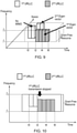
- An example of this is schematically shown in Figure 5 , which schematically represents how a set of grant-free frequency resources ranging from f1 to f2 that are configured for a terminal device to use for URLLC uplink transmissions may be shared for transmissions associated with a first block of URLLC data (lighter shading labelled first URLLC in the figure) and a second block of URLLC data (heavier shading labelled second URLLC in the figure). It will be appreciated these resources may be available for a number of terminal devices.
- the transmissions of the URLLC data blocks represented in Figure 5 are divided among time periods (transmission time intervals - TTIs) as discussed above with respect to Figure 3 .
- the start times of the TTIs represented in Figure 5 (and in the other figures representing series of TTIs as discussed herein) are labelled tn, where n is the number of TTIs after the first TTI containing transmissions for the first URLLC transmission involved in a collision.
- a TTI starting at tn may sometimes be referred to herein as TTI tn.
- Each TTI that includes transmissions for a given block of URLLC data supports one transmission of that block of data.
- TTI t0 comprises a first transmission for the first URLLC data block
- TTI t1 comprises a second transmission for the first URLLC data block (i.e. a first retransmission)
- TTI t2 comprises a third transmission for the first URLLC data block (i.e. a second retransmission)
- so forth When there is no collision between URLLC data blocks (e.g.
- the terminal device may select the amount of resource to use for the respective transmissions according to conventional techniques, for example having regard to radio channel conditions, available transmission power and the amount of redundancy required to support a desired level of reliability / BLER.
- the amount of resource used in each TTI is schematically indicated in Figure 5 by the extent of the shading in the relevant TTI. As can be seen in Figure 5 , the terminal device uses more than half the available radio resources in TTI t0 and TTI t1 to support the initial transmission and first retransmission of the first URLLC data block.
- the terminal device may, for example, determine that it should use this amount of resource to meet a target reliability for each transmission having regard to current channel conditions. As discussed above, an issue can arise when the terminal device needs to transmit a second URLLC block of data before it has finished transmitting the first block of URLLC data. In particular, there may not be enough of the available transmission resources remaining to support URLLC transmissions for the second block of data using the amount of data needed to meet a target reliability BLER for transmissions of that data.
- the terminal device is configured, in response to determining a second block of data has become available for transmission before a plurality of transmissions of a first block of data are complete, to modify an initial selection of transmission resources for the remaining transmissions of the first block to reduce the amount of transmission resources to be used for transmitting the first block and so increase the amount of transmission resources available for transmitting the second block.
- a first URLLC packet / data block arrives at the terminal device's transmission buffers and is transmitted using the configured grant-free resources.
- a second URLLC packet arrives at the terminal device's transmission buffers and is subsequently also transmitted using the grant-free resources. Since there are insufficient grant-free resources to carry both URLLC packets using the desired amount of resources for each, a redistribution of REs is made to compromise on how much resource is used for each data block in a given TTI.
- the first URLLC packet is, as noted above, repeated 4 times and each successive repetition is associated with a potential 25% reduction in resources that may be applied if there is a collision.
- this example based on 25% reductions is merely one approach, and different reductions may be applied for different orders of repetition in other implementations.
- the degree of reduction in the amount of resources for subsequent retransmissions that can be tolerated without too significant an impact on overall reliability in this, and other, examples will depend on the implementation at hand (e.g. taking account of how important the repetitions are to providing the target reliability).
- the first repetition (starting at t1) may be reduced by 25% compared to the initial transmission (starting at t0) if there is a collision.
- the first repetition (starting at t1) is in this example transmitted using the same amount of resource as the initial transmission.
- the second repetition (starting at t2) may be reduced by a further 25% compared to the initial transmission (starting at t0), i.e. by 50%, if there is a collision, which in the example of Figure 5 there is, and so the second repetition for the first URLLC data block (starting at t2) is in this example is transmitted using 50% of the resources used for the initial transmission (this may be achieved by using a higher coding rate, for example).
- the third repetition (fourth transmission) for the first URLLC data block / packet (starting at t3) may be reduced by a further 25% compared to the initial transmission (starting at t0), i.e. by 75%, if there is a collision, which in the example of Figure 5 there is, and so the third repetition for the first URLLC data block (starting at t3) is in this example transmitted using 25% of the resources used for the initial transmission (this may be achieved by using a higher coding rate, for example).
- Repetitions at different code rates may be soft-combined by the receiving entity in accordance with established techniques.
- the reduction of resources used for higher order repetitions of the first URLLC data block allow for more resources to be used for the second URLLC data block than would otherwise be the case.
- the amount of resources available for the initial transmission of the second URLLC (staring in TTI t2) is still less than would be used if there were not a collision (e.g. a higher than optimal coding rate is still needed for the initial transmission), but the initial transmission of the second URLLC data block makes use of all the remaining available resources.
- the second transmission (first retransmission) of the second URLLC data block (staring in TTI t3), all remaining resources in the relevant TTI are used in this example, after which the amount of resources used for transmissions for the second block of URLLC data returns to a level that matches what would conventionally be used to support the URLLC transmissions in the absence of collision.
- the second URLLC data block need not fully use all the available resources in TTI t3 if it can meet a desired reliability target using fewer resources.
- the second URLLC packet in the second transmission does use up all the resources available to help compensate for the reduction in resources for the initial transmission.
- the receiving entity will have successfully received the packet from the initial transmission (and / or an earlier retransmission) and so the receiving entity does not require further repetitions. More generally, the importance of each successive repeat transmission to ensuring successful detection will typically be less than the preceding transmission. Consequently, an acceptable degree of overall reliability may be achieved even with successively increasing reductions to the amount of resources for retransmissions.
- the degree of reduction applied to the amount of resource used for retransmissions of a first data block when a second data block becomes available for transmission may be dependent on the repetition level for the second data block (i.e. how many times, if any, the second data block has been transmitted). For example, a first transmission of the second data block might be made without any reduction to the amount of resource that would have been used for this transmission if there were no collision, and the retransmission of the first data block in this TTI may simply be forced to use only whatever resources remain available. This recognises that the first transmission of a data block has a relatively high probability of being successfully received and decoded at a receiving entity and subsequent repetitions increase this probability marginally.
- a first transmission might have a 99% probability of being received whilst the combination of a first a second transmissions might have a 99.9% probability of being received.
- the resources occupied by the second data block might thus be reduced gradually in each successive repetition (e.g. as discussed above for the first data block).
- the degree to which resources of an initial transmission are reduced in a collision situation may take account of a relative priority assigned to the first data block and the second data block. For example: (i) if the first and second data blocks have equal priority, resources used for the first transmission are reduced by 25% per TTI under collision situations; (ii) if the first data block has a higher priority than the second data block, resources used the first transmission are reduced by 10% per TTI under collision situations; (iii) if the first data block has a lower priority than the second data block, resources used the first transmission are reduced by 40% per TTI under collision situations. It will be appreciated these specific reductions are merely examples given for the purpose of explanation. Other reductions for different scenarios may be applied in other implementations.
- Figure 6 is similar to, and will be understood from, Figure 5.
- Figure 6 again represents an example in which a first URLLC transmission (with 4 repeats) starts at time t0 whilst a second URLLC transmission (with 4 repeats) starts at time t2, thereby colliding with the repetitions for the first URLLC transmission.
- the resources are distributed to preferentially support transmission of the second URLLC data block compared to the first URLLC data block (since the first URLLC data block has had more previous transmissions) in the general manner described above.
- the initial transmission of each URLLC packet is always transmitted in full, i.e.
- the terminal device reduces the transmission resources used by the third transmission of the first URLLC data block to whatever level is needed to allow the first transmission of the second URLLC data block to use 100% of the resource that it requires (i.e. the amount of resources it would have selected for use if there were no collision).
- the second transmission of the second URLLC data block might be made with reduced resources if necessary, but in this example the amount of resources used for the transmission of the first URLLC data block is reduced by 75% in accordance with the principles discussed above in relation to Figure 5 , and so in fact in this case there is sufficient remaining resources to transmit the second (and subsequent) transmissions of the second URLLC data block without reducing the amount of resources used below what would be selected for use if there were no collision.
- the available resource that needs to be distributed might be an available transmission power for the terminal device instead of, or in addition to, physical time and frequency resources.
- a terminal device at cell edge may not have sufficient power to fully transmit more than one simultaneous URLLC TB (transport block), and hence a distribution of transmission power may be appropriate.
- the general principles set out above in relation to sharing an amount of transmission resource comprising a plurality of time and / or frequency resources may thus be applied broadly in the same way in relation to sharing an amount of transmission resource comprising a transmission power budget.
- the power used for transmitting a first URLLC data block may be increasingly reduced (if necessary) for each successive repetition in accordance with the general principles discussed above in relation to Figure 5 (albeit in relation to a different kind of transmission resource).
- a first / initial transmission for a data block might be always transmitted using full power with remaining repetitions being transmitted with a reduced power (if necessary), for example where the reduction in power is a percentage of the initial full power (e.g. 25%) for each successive repetition.
- full power need not correspond with the absolute maximum power the terminal device is physically capable of transmitting, but may be a level the terminal device would use for an URLLC transmission if there were not a collision, for example having regard to a target BLER (block error rate) for the transmission and / or any other constraints, such as a requirement to not cause too much interference for other terminal devices operating in the network.
- FIG. 7 An example approach based on power sharing is represented in Figure 7 which schematically represents the amount of transmission power used for transmitting a first URLLC data block (area shown with no shading and dotted outline) and a second URLLC data block (area shown with shading and solid outline).
- the horizontal axis represents time, and the vertical axis represents transmission power.
- the available transmission power that may be physically transmitted by the terminal device is marked "Available Power” and the full (“Required”) transmission power for an uplink transmission (i.e. the transmission power that would normally be used when there is no collision) is also marked.
- a first URLLC transmission / repetition starts at time t0 with its four repetitions ending at time t4 while a second URLLC transmission / repetition starts at time t2.
- the available transmission power is preferentially allocated to the transmission of the second URLLC data block since this is the one with fewer previous transmissions.
- the frequency resources used by the overlapping URLLC transmissions do not necessarily need to be reassigned. For example, if the frequency resources used by the two transmissions are orthogonal (e.g. use separate sets of subcarriers), then both of sets of frequency resources can be transmitted at the same time, albeit with the redistribution of transmit power.
- the available resources that need to be shared may be MIMO resources (e.g. available MIMO streams).
- MIMO resources e.g. available MIMO streams.
- the different URLLC transmissions can be transmitted using different MIMO streams.
- the first URLLC packet that has already made some repetitions can use the weaker MIMO stream, i.e. one with a weaker Eigen value, whilst the second URLLC packet can use a stream with a stronger Eigen value.
- Figure 8 is in some respects similar to, and will be understood from Figures 5 and 6 , but in addition to representing time and frequency axes for the available physical resource elements, also represents a space axis representing available MIMO configurations.
- a first URLLC packet with four repeats starts to be transmitted at time t0 followed by a second URLLC transmission with four repeats starting at time t2. Since the configured grant-free resource is sufficient to transmit only a single URLLC TB, the two URLLC TBs are transmitted using MIMO.
- the first URLLC packet is initially (i.e. in TTIs t0 and t1 when there is no collision) transmitted using the MIMO stream with the strongest Eigen value, namely Eigen vector 1 (1st Eigen vector) as schematically indicated in Figure 8 .
- the first URLLC data block has already had two transmissions and is transferred to using the second Eigen vector (corresponding to a weaker stream), whilst the second URLLC making its first transmission uses the first (stronger) Eigen vector.
- the first transmission of the third URLLC transmission may use the first Eigen vector
- the second URLLC transmission may uses the second Eigen vector
- the first URLLC transmission uses a weaker still third Eigen vector.
- Figure 8 represents another approach in which an amount of the available transmission resources used for transmitting later repetitions of a first block of data is reduced to allow more transmission resources to be used for transmitting initial transmissions of a second block of data.
- the term "amount of resource” does not necessarily relate to numerical amount of a countable resource, but may also relate to the quality of a resource - i.e. its ability to convey data.
- using a weaker MIMO stream may be considered as corresponding to using a reduced amount of available transmission resource as compared to using a stronger MIMO scheme (e.g. the amount of available transmission resource corresponds to the strength of the MIMO configuration).
- transmissions from a MIMO-capable terminal device may be performed without MIMO unless two packets need to be transmitted at the same time.
- later repetitions of a first URLLC transmission may use the weaker MIMO stream while simultaneous initial transmissions / repetitions of a second URLLC transmission may use a stronger MIMO stream.
- Figure 9 An example in which this approach is used is schematically shown in Figure 9 , which is similar to, and will be understood from, Figure 8 .
- the first URLLC packet is transmitted without MIMO.
- a second URLLC packet becomes available for transmission in the terminal device's transmission buffers.
- the second URLLC packet is then sent on a stronger MIMO stream (associated with the first Eigen vector) while the re-transmissions of the first URLLC packet are transmitted on the weaker MIMO stream (associated with the second Eigen vector).
- the re-transmissions of the first URLLC packets are complete, and the subsequent repetitions for the second URLLC packet may continue to be transmitted on the same MIMO stream, or may be switched to transmission without the MIMO.
- the first transmission / repetition of a URLLC packet might always be transmitted without MIMO, while subsequent retransmissions may use MIMO, with the strongest streams being used for transmitting data blocks that have been previously transmitted the fewest number of times.
- the initial transmission of the second data block may be transmitted without MIMO, and the repetition of the first data block in the TTI starting at t2 in Figure 9 may be missed (i.e. not transmitted at all).
- the second transmission of the second URLLC data block and the 3rd transmission of the first URLLC data block may then be transmitted in the TTI starting at t3 using MIMO where the second URLLC uses the stronger MIMO stream.
- the transmissions made without MIMO could instead be made using all available MIMO resources (i.e. single user-MIMO transmitting two streams simultaneously).
- the respective URLLC data blocks may be transmitted using MUST (Multiuser Superposition Transmission - see the 3GPP document TR36.859: Technical Specification Group Radio Access Network; "Study on Downlink Multiuser Superposition Transmission (MUST) for LTE"; (Release 13), Nov 2015 [3 ]).
- MUST Multiuser Superposition Transmission
- MUST Technical Specification Group Radio Access Network
- MUST Student on Downlink Multiuser Superposition Transmission
- the first URLLC data block i.e. the one having had the most previous transmissions
- Successive Interference Cancellation techniques may be employed to recover the respective URLLC transmissions (once the first URLLC data block has been successfully received by the receiving entity, it can be simply cancelled from the MUST processing).
- the MUST transmission scheme is applied to a single user (i.e. one URLCC transmission acts as one virtual user of the Multiuser Superposition Transmission scheme and the other URLLC transmission acts as another virtual user of the MUST scheme).
- the repetition of the first URLLC transmission might simply be stopped. That is to say, the reduction in resources for the retransmissions of the first data block may be a complete reduction / termination.
- Figure 10 An example of this approach is schematically shown in Figure 10 , which is similar to, and will be understood from, the other figures discussed above.
- a first URLLC transmission starts at time t0.
- the second URLLC packet becomes available for transmission and the repetition of the first URLLC transmission is stopped. That is to say, the repetition of a URLLC transmission may be terminated early if another URLLC transmission in the same terminal device needs transmitting.
- a re-transmission of the first URLLC transmission can be scheduled by the base station if the first URLLC transmission is incorrectly received (and the base station will have had time to decode the first URLLC transmission and prepare an ACK/NACK response during the time taken for the terminal device to transmit the second URLLC transmission).
- a first URLLC transmission may be transmitted on grant-free resources, and if the terminal device receives a DCI indicating another URLLC transmission whilst the repetition of the first URLLC transmission is ongoing, this DCI may be taken to implicitly also indicate that the first URLLC repetition is to be terminated.
- This approach is based on the recognition that a scheduling message for a (granted) URLLC transmission from the receiving entity may indicate the receiving entity is likely to have already received the first URLLC transmission so that subsequent repetitions are not necessary.
- time interleaving may be applied to the at least two URLLC transmissions.
- the K repetitions of a given URLLC data block do not completely fill up the targeted latency (e.g. 1 ms)
- the first URLLC packet may then complete its 4 repetitions starting at time t4, after which the second URLLC continues the remainder of its repetitions, starting at t6.
- interleaving can be done on a single TTI, rather than pair of TTIs, basis (or higher groupings in scenarios with more repetitions).
- interleaving in frequency may be performed for simultaneous URLLC transmissions. This may be applicable even if there are sufficient resources to carry the at least two URLLC transmissions fully. This allows for frequency diversity in the transmission.
- An example is shown in Figure 12 , where a first URLLC packet is transmitted at time t0 and at time t2, the second URLLC packet is transmitted.
- frequency interleaving is performed, where the REs between the two URLLC transmissions are interleaved and spread across the frequency resources occupied by both URLLC transmissions.
- the percentage of REs occupied by each URLLC transmission during the period of interleaving may be based on the above-described approaches for sharing the available resources (e.g. as shown in Figures 5 and 6 ).
- an indicator may transmitted by the terminal device to the receiving entity to indicate when there is URLLC collision.
- This indicator may thus be used to inform the receiving entity that an amount of transmission resource for repetitions of a data block (e.g. in terms of the physical resources used, MIMO transmission characteristics (e.g. Transmission Mode, MIMO stream), early termination or interleaving) for the first URLLC data block have changed (typically being reduced) due to the transmission of a second URLLC data block.
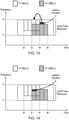
- the collision indicator may be transmitted after completion of the transmissions for the first data block and indicate when the change occurred, for example as schematically represented in Figure 13 , or may be transmitted at the start of the transmissions on the second data block, for example as schematically indicated in Figure 14 .
- the indicator may be transmitted as part of a second URLLC transmission (or first URLLC transmission), e.g. as a header, or it can be transmitted using an independent physical channel (e.g. PUCCH), as independent UCI (Uplink Control Information) or on a new control channel.
- PUCCH Physical channel
- UCI Uplink Control Information
- Transmitting the indicator at the start of the second URLLC transmission would enable the receiving entity to soft combine the first URLLC repetitions that coincide with the second URLLC transmission immediately rather than after all of the first URLLC repetitions are completed.
- the receiver entity may thus determine from the indicator that an initial selection of resources to use for transmitting the first block of data has been modified, and may adapt its receiver processing accordingly (for example to take account of a difference in coding scheme / a difference in the selected resources used by the terminal device for repetitions of a first block of data).
- a terminal device may convey to the receiver entity that there has been a modification to the initially selected resources through use of a specific signature sequence or preamble transmitted in association with the respective transmissions / repeat transmissions.
- the base station may be configured to determine the two different signature sequences to identify respective transmissions from the terminal device.
- the terminal device might not transmit any indicator of the modified selection of transmission resources, in which case the base station may be required to simply apply a blind detection scheme to detect the different transmissions.
- FIG 15 represents a scenario in which a base station transmits a first downlink URLLC packet (represented by light shading in Figure 15 ) to a terminal device at time to. It is assumed a NACK is received from the terminal device and so at t1, the base station schedules a retransmission of the first URLLC packet. At the same time a second URLLC transmission (represented by medium shading in Figure 15 ) is scheduled to the same terminal device, thereby leading to more than two URLLC transmissions at the same time. Each transmission may be scheduled using control channel signalling (represented by heavy shading in Figure 15 ).
- a DCI message for the repeat transmission of the first data block may contain different information to a DCI message for the initial transmission of the first data block.
- the DCI message for a repeat transmission might not contain some information relating to characteristics of the data block that remain the same, for example transport block size, and a terminal device receiving the data may simply use the relevant information from the previous DCI message for the initial transmission of the first data block.
- the DCI message for the repeat transmission of the first data block may use a different (and more compact) DCI format than the DCI message for the initial transmission of the first data block.
- the control channel allocation signalling associated with a retransmission of the first URLLC data may also schedule resources for the initial transmission of the second URLLC data. That is to say, the DCI scheduling for the retransmission of the first data may also schedule the transmission of the second data such that a single DCI is transmitted to schedule at least two URLLC transmissions.
- the control channel such as a PDCCH in an LTE context, carries a DCI that schedules the retransmission of the first URLLC packet and schedules the first transmission for the second URLLC packet.
- control channel signalling associated with the initial transmission of the second data block is used to schedule a retransmission of the first data block (i.e. it may be the retransmission of the first data block that does not have its own DCI rather than the initial transmission of the second data block as represented in Figure 16 ).
- a single bit in a field in the DCI for the initial transmission of the second data block may be used to tell the terminal device that a retransmission of the first URLLC packet is being scheduled (e.g. using corresponding transmission characteristics to the initial transmission), while the remaining fields in the DCI may be used for scheduling the second URLLC packet.
- Figure 17 is a flow diagram schematically representing some aspects of operation in a wireless telecommunications system in accordance with certain embodiments of the present disclosure.
- step S1 a terminal device determines a first block of data has become available for transmission.
- the reason why the data has become available for transmission, and the content of the data, is not significant to the principles described herein.
- step S2 the terminal device determines an initial selection of transmission resources for a plurality of transmissions of the first block of data in a corresponding plurality of time periods. This selection may be made having regard to conventional scheduling considerations in wireless telecommunications systems.
- step S3 the terminal device begins transmission of the first block of data in accordance with the initial selection of transmission resources.
- step S4 the terminal device determines a second block of data has become available for transmission before the plurality of transmissions for the first block of data are complete. Again, the reason why the data has become available for transmission, and the content of the data itself, is not significant to the principles described herein.
- step S5 the terminal device modifies the initial selection of transmission resources for remaining repeat transmissions of the first block of data to reduce the amount of transmission resources selected for the remaining repeat transmissions.
- step S6 the terminal device determines a selection of transmission resources for a plurality of transmissions of the second block of data in a corresponding plurality of time periods include the time periods remaining for repeat transmissions of the first block of data.
- step S7 the terminal device transmits the second block of data according to the selection of transmission resources for the second block of data and transmit remaining transmissions for the first block of data in accordance with the modified selection of transmission resources for the first block of data.
- predetermined / predefined information may in general be established, for example, by definition in an operating standard for the wireless telecommunication system, or in previously exchanged signalling between the base station and terminal devices, for example in system information signalling, or in association with radio resource control setup signalling.
- a terminal device may be configured to reduce the amount of resource allocated for use for retransmissions of uplink data in successive repetitions of a block of data regardless of whether there is any collision.
- a terminal device may be configured to taper off, or otherwise reduce, the resources used for successive repetitions during uplink transmission of a data block regardless of whether there are other data blocks that need transmitting at the same time.
- the terminal devoice may thus be configured to operate according to a predefined scheme for automatically reducing the resources applied to retransmissions of a data block, i.e. so that re-transmissions are made to be less resource consuming than initial transmissions, thereby leaving more space (in terms of resources) for other data blocks that do become available for uplink before the retransmissions are complete.
- a selection of transmission resources for a plurality of transmissions of the second block of data in a corresponding plurality of time periods is made and the second block of data transmitted accordingly, and remaining transmissions for the first block of data are made in accordance with the modified selection of transmission resources for these transmissions of the first block of data.
- uplink communications may also be used in respect of downlink communications. That is to say, in the general case these principles may be adopted in respect of communications between a transmitting entity (which in the majority of examples discussed above is a terminal device, but which in other examples could be network infrastructure equipment) and a receiving entity (which in the majority of examples discussed above is network infrastructure equipment, but which in other examples could be a terminal device).
- a transmitting entity which in the majority of examples discussed above is a terminal device, but which in other examples could be network infrastructure equipment
- receiving entity which in the majority of examples discussed above is network infrastructure equipment, but which in other examples could be a terminal device
Landscapes
- Engineering & Computer Science (AREA)
- Computer Networks & Wireless Communication (AREA)
- Signal Processing (AREA)
- Mobile Radio Communication Systems (AREA)
Claims (15)
- Procédé de transmission de blocs de données depuis une entité émettrice (508) jusqu'à une entité réceptrice (504) dans un système de télécommunications sans fil (500) dans lequel des blocs de données sont transmis une pluralité de fois dans une pluralité correspondante d'intervalles de temps en utilisant des ressources de transmission dans chaque intervalle de temps, sélectionnées parmi les ressources de transmission disponibles pour transmettre les blocs de données, le procédé comprenant :la détermination de ce qu'un premier bloc de données est devenu disponible en vue d'une transmission depuis l'entité émettrice jusqu'à l'entité réceptrice,la détermination d'une sélection initiale de ressources de transmission pour une pluralité de transmissions du premier bloc de données dans une pluralité correspondante d'intervalles de temps, la pluralité de transmissions du premier bloc de données comprenant une première transmission et une ou plusieurs transmissions de répétition,le démarrage de la transmission du premier bloc de données en utilisant la sélection initiale de ressources de transmission,la détermination de ce qu'un second bloc de données est devenu disponible en vue d'une transmission depuis l'entité émettrice jusqu'à l'entité réceptrice avant que soit achevée la pluralité de transmissions concernant le premier bloc de données,la modification de la sélection initiale des ressources de transmission pour les intervalles de temps restant pour les transmissions de répétition du premier bloc de données afin de réduire la quantité de ressources de transmission sélectionnées pour les transmissions de répétition du premier bloc de données qui n'ont pas encore été réalisées, ce qui augmente ainsi la quantité de ressources de transmission disponibles pour transmettre le second bloc de données pendant ces intervalles de temps restant pour les transmissions de répétition du premier bloc de données,la détermination d'une sélection de ressources de transmission pour au moins une transmission du second bloc de données dans au moins un intervalle de temps correspondant qui chevauche les intervalles de temps restant pour les transmissions de répétition du premier bloc de données en fonction de la sélection initiale des ressources de transmission permettant de transmettre le premier bloc de données, etla transmission du second bloc de données en utilisant la sélection de ressources de transmission pour le second bloc de données et la communication des transmissions de répétition restantes pour le premier bloc de données en fonction de la sélection modifiée des ressources de transmission pour le premier bloc de données.
- Procédé selon la revendication 1, dans lequel la mesure dans laquelle la quantité de ressources de transmission destinées à des transmissions de répétition du premier bloc de données dans les intervalles respectifs parmi les intervalles de temps restant sélectionnés initialement pour la transmission du premier bloc de données est réduite lorsque la modification de la sélection initiale de ressources de transmission pour les intervalles de temps restant pour les transmissions de répétition du premier bloc de données dépend du nombre de transmissions du premier bloc de données qui ont déjà été réalisées.
- Procédé selon la revendication 1, dans laquelle la mesure dans laquelle la quantité de ressources de transmission destinées à des transmissions de répétition du premier bloc de données dans les intervalles respectifs parmi les intervalles de temps restant sélectionnés initialement pour la transmission du premier bloc de données est réduite lorsque la modification de la sélection initiale de ressources de transmission pour les intervalles de temps restant pour les transmissions de répétition du premier bloc de données dépend du nombre de transmissions du premier bloc de données qui ont déjà été réalisées avant les intervalles de temps respectifs.
- Procédé selon la revendication 1, dans laquelle la mesure dans laquelle la quantité de ressources de transmission destinées à des transmissions de répétition du premier bloc de données dans les intervalles respectifs parmi les intervalles de temps restant sélectionnés initialement pour la transmission du premier bloc de données est réduite lorsque la modification de la sélection initiale de ressources de transmission pour les intervalles de temps restant pour les transmissions de répétition du premier bloc de données augmente pour des transmissions suivantes de répétition du premier bloc de données.
- Procédé selon la revendication 1, dans lequel la mesure dans laquelle la quantité de ressources de transmission destinées à des transmissions de répétition du premier bloc de données dans les intervalles respectifs parmi les intervalles de temps restant sélectionnés initialement pour la transmission du premier bloc de données est réduite lorsque la modification de la sélection initiale de ressources de transmission pour les intervalles de temps restant pour les transmissions de répétition du premier bloc de données est suffisante pour permettre au moins la réalisation d'une transmission du second bloc de données avec une quantité de ressources de transmission qui n'a pas été réduite pour permettre une transmission de répétition du premier bloc de données.
- Procédé selon la revendication 1, dans lequel la modification de la sélection initiale de ressources de transmission pour les intervalles de temps restant pour des transmissions de répétition du premier bloc de données pour réduire la quantité de ressources de transmission sélectionnées pour des transmissions de répétition du premier bloc de données qui n'ont pas encore été réalisées comprend l'annulation d'une ou plusieurs des transmissions de répétition du premier bloc de données qui n'ont pas encore été réalisées.
- Procédé selon la revendication 1, dans lequel les ressources de transmission comprenant la sélection des ressources de transmission pour le second bloc de données et les ressources de transmission comprenant la sélection modifiée de ressources de transmission pour le premier bloc de données sont entrelacées dans le domaine des fréquences.
- Procédé selon la revendication 1, dans lequel les ressources de transmission disponibles à partir desquelles sont réalisées les sélections respectives de ressources de transmission pour transmettre les blocs respectifs de données comprennent au moins l'une parmi :une pluralité de fréquences disponibles pour la transmission des blocs de données,une pluralité d'intervalles de temps disponibles pour la transmission des blocs de données,la quantité d'énergie disponible pour la transmission des blocs de données,une pluralité de configurations d'entrées et sorties multiples, MIMO, disponibles pour la transmission des blocs de données, etune pluralité de configurations de transmission multiutilisateurs par superposition, MUST, disponibles pour la transmission des blocs de données.
- Procédé selon la revendication 1, comprenant en outre la transmission par l'entité émettrice à l'entité réceptrice d'une indication montrant qu'a été modifiée la sélection initiale des ressources de transmission pour une pluralité de transmissions du premier bloc de données.
- Entité émettrice (508) conçue pour transmettre des blocs de données à une entité réceptrice (504) dans un système de télécommunications sans fil (500) dans lequel des blocs de données sont transmis une pluralité de fois dans une pluralité correspondante d'intervalles de temps en utilisant des ressources de transmission dans chaque intervalle de temps, sélectionnées parmi des ressources de transmission disponibles pour la transmission des blocs de données, l'entité émettrice comprenant des circuits de contrôleur (508b) et des circuits d'émetteur récepteur (508a) configurés pour fonctionner ensemble de sorte à ce que l'entité émettrice soit adaptée pour :déterminer qu'un premier bloc de données est devenu disponible en vue d'une transmission depuis l'entité émettrice jusqu'à l'entité réceptrice,déterminer une sélection initiale de ressources de transmission pour une pluralité de transmissions du premier bloc de données dans une pluralité correspondante d'intervalles de temps, la pluralité de transmissions du premier bloc de données comprenant une première transmission et une ou plusieurs transmissions de répétition,démarrer la transmission du premier bloc de données en utilisant la sélection initiale de ressources de transmission,déterminer qu'un second bloc de données est devenu disponible en vue d'une transmission depuis l'entité émettrice jusqu'à l'entité réceptrice avant que soit achevée la pluralité de transmissions concernant le premier bloc de données,modifier la sélection initiale des ressources de transmission pour les intervalles de temps restant pour les transmissions de répétition du premier bloc de données afin de réduire la quantité de ressources de transmission sélectionnées pour les transmissions de répétition du premier bloc de données qui n'ont pas encore été réalisées, ce qui augmente ainsi la quantité de ressources de transmission disponibles pour transmettre le second bloc de données pendant ces intervalles de temps restant pour les transmissions de répétition du premier bloc de données,déterminer une sélection de ressources de transmission pour au moins une transmission du second bloc de données dans au moins un intervalle de temps correspondant qui chevauche les intervalles de temps restant pour les transmissions de répétition du premier bloc de données en fonction de la sélection initiale des ressources de transmission permettant de transmettre le premier bloc de données, ettransmettre le second bloc de données en utilisant la sélection de ressources de transmission pour le second bloc de données et émettre les transmissions de répétition restantes pour le premier bloc de données en fonction de la sélection modifiée des ressources de transmission pour le premier bloc de données.
- Circuits (508a, 508b) destinés à une entité émettrice (508) conçus pour transmettre des blocs de données à une entité réceptrice (504) dans un système de télécommunications sans fil (500) dans lequel des blocs de données sont transmis une pluralité de fois dans une pluralité correspondante d'intervalles de temps en utilisant des ressources de transmission dans chaque intervalle de temps, sélectionnées parmi des ressources de transmission disponibles pour la transmission des blocs de données, les circuits comprenant des circuits de contrôleur (508b) et des circuits d'émetteur récepteur (508a) configurés pour fonctionner ensemble de sorte à ce que les circuits soient adaptés pour :déterminer qu'un premier bloc de données est devenu disponible en vue d'une transmission depuis l'entité émettrice jusqu'à l'entité réceptrice,déterminer une sélection initiale de ressources de transmission pour une pluralité de transmissions du premier bloc de données dans une pluralité correspondante d'intervalles de temps, la pluralité de transmissions du premier bloc de données comprenant une première transmission et une ou plusieurs transmissions de répétition,démarrer la transmission du premier bloc de données en utilisant la sélection initiale de ressources de transmission,déterminer qu'un second bloc de données est devenu disponible en vue d'une transmission depuis l'entité émettrice jusqu'à l'entité réceptrice avant que soit achevée la pluralité de transmissions concernant le premier bloc de données,modifier la sélection initiale des ressources de transmission pour les intervalles de temps restant pour les transmissions de répétition du premier bloc de données afin de réduire la quantité de ressources de transmission sélectionnées pour les transmissions de répétition du premier bloc de données qui n'ont pas encore été réalisées, ce qui augmente ainsi la quantité de ressources de transmission disponibles pour transmettre le second bloc de données pendant ces intervalles de temps restant pour les transmissions de répétition du premier bloc de données,déterminer une sélection de ressources de transmission pour au moins une transmission du second bloc de données dans au moins un intervalle de temps correspondant qui chevauche les intervalles de temps restant pour les transmissions de répétition du premier bloc de données en fonction de la sélection initiale des ressources de transmission permettant de transmettre le premier bloc de données, ettransmettre le second bloc de données en utilisant la sélection de ressources de transmission pour le second bloc de données et émettre les transmissions de répétition restantes pour le premier bloc de données en fonction de la sélection modifiée des ressources de transmission pour le premier bloc de données.
- Procédé de réception de blocs de données émis depuis une entité émettrice (508) au niveau d'une entité réceptrice (504) dans un système de télécommunications sans fil (500) dans lequel des blocs de données sont transmis une pluralité de fois dans une pluralité correspondante d'intervalles de temps en utilisant des ressources de transmission dans chaque intervalle de temps, sélectionnées parmi des ressources de transmission disponibles pour transmettre les blocs de données, le procédé comprenant :la détermination d'une sélection initiale de ressources de transmission permettant de recevoir une pluralité de transmissions d'un premier bloc de données dans une pluralité correspondante d'intervalles de temps, la pluralité de transmissions pour le premier bloc de données comprenant une première transmission et une ou plusieurs transmissions de répétition,le démarrage de la réception du premier bloc de données en utilisant la sélection initiale de ressources de transmission,la détermination d'une modification sur la sélection initiale de ressources de transmission pour des intervalles de temps restant pour des transmissions de répétition du premier bloc de données, laquelle réduit la quantité de ressources de transmission pour des transmissions de répétition du premier bloc de données qui n'ont pas encore été réalisées, ce qui augmente ainsi la quantité de ressources de transmission disponibles pour l'entité émettrice pour transmettre un second bloc de données qui est devenu disponible en vue d'une transmission depuis l'entité émettrice jusqu'à l'entité réceptrice,la détermination d'une sélection de ressources de transmission permettant de recevoir une transmission du second bloc de données dans au moins un intervalle de temps correspondant qui chevauche les intervalles de temps restant pour des transmissions de répétition du premier bloc de données en fonction de la sélection initiale de ressources de transmission permettant de transmettre le premier bloc de données, etla réception du second bloc de données en utilisant la sélection de ressources de transmission pour le second bloc de données et la réception de transmissions de répétition restantes pour le premier bloc de données en fonction de la sélection modifiée de ressources de transmission pour le premier bloc de données.
- Entité réceptrice (504) conçue pour recevoir des blocs de données émis par une entité émettrice (508) dans un système de télécommunications sans fil (500) dans lequel des blocs de données sont transmis une pluralité de fois dans une pluralité correspondante d'intervalles de temps en utilisant des ressources de transmission dans chaque intervalle de temps, sélectionnées parmi des ressources de transmission disponibles pour la transmission des blocs de données, l'entité réceptrice comprenant des circuits de contrôleur (504b) et des circuits d'émetteur récepteur (504a) configurés pour fonctionner ensemble de sorte à ce que l'entité réceptrice soit adaptée pour :déterminer une sélection initiale de ressources de transmission permettant de recevoir une pluralité de transmissions d'un premier bloc de données dans une pluralité correspondante d'intervalles de temps, la pluralité de transmissions pour le premier bloc de données comprenant une première transmission et une ou plusieurs transmissions de répétition,démarrer la réception du premier bloc de données en utilisant la sélection initiale de ressources de transmission,déterminer une modification sur la sélection initiale de ressources de transmission pour des intervalles de temps restant pour des transmissions de répétition du premier bloc de données, laquelle réduit la quantité de ressources de transmission pour des transmissions de répétition du premier bloc de données qui n'ont pas encore été réalisées, ce qui augmente ainsi la quantité de ressources de transmission disponibles pour l'entité émettrice pour transmettre un second bloc de données qui est devenu disponible en vue d'une transmission depuis l'entité émettrice jusqu'à l'entité réceptrice,déterminer une sélection de ressources de transmission permettant de recevoir une transmission du second bloc de données dans au moins un intervalle de temps correspondant qui chevauche les intervalles de temps restant pour des transmissions de répétition du premier bloc de données en fonction de la sélection initiale de ressources de transmission permettant de transmettre le premier bloc de données, etrecevoir le second bloc de données en utilisant la sélection de ressources de transmission pour le second bloc de données et recevoir des transmissions de répétition restantes pour le premier bloc de données en fonction de la sélection modifiée de ressources de transmission pour le premier bloc de données.
- Circuits (504a, 504b) destinés à une entité réceptrice (504) conçue pour recevoir des blocs de données émis par une entité émettrice (508) dans un système de télécommunications sans fil (500) dans lequel des blocs de données sont transmis une pluralité de fois dans une pluralité correspondante d'intervalles de temps en utilisant des ressources de transmission dans chaque intervalle de temps, sélectionnées parmi des ressources de transmission disponibles pour la transmission des blocs de données, les circuits comprenant des circuits de contrôleur (504b) et des circuits d'émetteur récepteur (504a) configurés pour fonctionner ensemble de sorte à ce que les circuits soient adaptés pour :déterminer une sélection initiale de ressources de transmission permettant de recevoir une pluralité de transmissions d'un premier bloc de données dans une pluralité correspondante d'intervalles de temps, la pluralité de transmissions pour le premier bloc de données comprenant une première transmission et une ou plusieurs transmissions de répétition,démarrer la réception du premier bloc de données en utilisant la sélection initiale de ressources de transmission,déterminer une modification sur la sélection initiale de ressources de transmission pour des intervalles de temps restant pour des transmissions de répétition du premier bloc de données, laquelle réduit la quantité de ressources de transmission pour des transmissions de répétition du premier bloc de données qui n'ont pas encore été réalisées, ce qui augmente ainsi la quantité de ressources de transmission disponibles pour l'entité émettrice pour transmettre un second bloc de données qui est devenu disponible en vue d'une transmission depuis l'entité émettrice jusqu'à l'entité réceptrice,déterminer une sélection de ressources de transmission permettant de recevoir une transmission du second bloc de données dans au moins un intervalle de temps correspondant qui chevauche les intervalles de temps restant pour des transmissions de répétition du premier bloc de données en fonction de la sélection initiale de ressources de transmission permettant de transmettre le premier bloc de données, etrecevoir le second bloc de données en utilisant la sélection de ressources de transmission pour le second bloc de données et recevoir des transmissions de répétition restantes pour le premier bloc de données en fonction de la sélection modifiée de ressources de transmission pour le premier bloc de données.
- Système de télécommunications sans fil (500) comprenant l'entité émettrice (508) de la revendication 10 et l'entité réceptrice (504) de la revendication 13.
Applications Claiming Priority (2)
| Application Number | Priority Date | Filing Date | Title |
|---|---|---|---|
| EP17162407 | 2017-03-22 | ||
| PCT/EP2018/057078 WO2018172382A1 (fr) | 2017-03-22 | 2018-03-20 | Appareil et procédés de télécommunications sans fil |
Publications (2)
| Publication Number | Publication Date |
|---|---|
| EP3602877A1 EP3602877A1 (fr) | 2020-02-05 |
| EP3602877B1 true EP3602877B1 (fr) | 2022-02-16 |
Family
ID=58448345
Family Applications (1)
| Application Number | Title | Priority Date | Filing Date |
|---|---|---|---|
| EP18711131.5A Active EP3602877B1 (fr) | 2017-03-22 | 2018-03-20 | Appareil et procédés de télécommunications sans fil |
Country Status (4)
| Country | Link |
|---|---|
| US (1) | US10887055B2 (fr) |
| EP (1) | EP3602877B1 (fr) |
| CN (1) | CN110431781B (fr) |
| WO (1) | WO2018172382A1 (fr) |
Families Citing this family (17)
| Publication number | Priority date | Publication date | Assignee | Title |
|---|---|---|---|---|
| CN109937589B (zh) * | 2017-08-11 | 2021-03-23 | 华为技术有限公司 | 发送和接收数据的方法和装置 |
| CN111919409B (zh) * | 2018-03-26 | 2023-05-05 | Lg电子株式会社 | 在无线通信系统中发送和接收物理信号和/或信道的方法和用于该方法的设备 |
| WO2019201421A1 (fr) * | 2018-04-16 | 2019-10-24 | Nokia Technologies Oy | Pré-annulation d'interférence pour des communications à latence ultra faible multi-utilisateurs dans des réseaux sans fil |
| WO2020020815A1 (fr) * | 2018-07-25 | 2020-01-30 | Sony Corporation | Station de base, équipement d'utilisateur, circuits, système de télécommunications mobiles et procédé |
| US11791951B2 (en) * | 2018-08-09 | 2023-10-17 | Huawei Technologies Co., Ltd. | Mini-slot based repetition and frequency hopping |
| US11070254B2 (en) | 2018-09-28 | 2021-07-20 | At&T Intellectual Property I, L.P. | Decoding data in new radio ultra-reliable low latency communications with multiple transmission points |
| CN111224742B (zh) * | 2018-11-23 | 2021-08-20 | 华为技术有限公司 | 发送信息的方法和装置 |
| EP3900451B1 (fr) | 2018-12-20 | 2025-07-09 | Sony Group Corporation | Dispositif de communication, équipement d'infrastructure et procédés |
| EP3909299A1 (fr) | 2019-01-11 | 2021-11-17 | Sony Group Corporation | Dispositifs de communication, équipement d'infrastructure et procédés |
| EP3925338B1 (fr) | 2019-02-14 | 2025-09-10 | Sony Group Corporation | Dispositif de communication, équipement d'infrastructure et procédés |
| WO2020165039A1 (fr) | 2019-02-14 | 2020-08-20 | Sony Corporation | Dispositif terminal, système et procédés |
| EP3949629B1 (fr) * | 2019-04-01 | 2025-09-17 | Nokia Technologies Oy | Multiplexage intra-ue dans des réseaux sans fil 5g |
| WO2020200163A1 (fr) * | 2019-04-02 | 2020-10-08 | 电信科学技术研究院有限公司 | Procédé de transmission d'informations et terminal |
| WO2021155606A1 (fr) * | 2020-02-07 | 2021-08-12 | Oppo广东移动通信有限公司 | Procédé et appareil de transmission de signal, et dispositif associé |
| CN113543158B (zh) * | 2020-04-14 | 2023-06-02 | 维沃移动通信有限公司 | 确定数据传输层数的方法及装置、通信设备 |
| DE112021005575T5 (de) | 2020-10-22 | 2023-08-24 | Sony Group Corporation | Kommunikationsvorrichung, infrastrukturausrüstung und verfahren |
| CN116684045A (zh) * | 2022-02-21 | 2023-09-01 | 大唐移动通信设备有限公司 | 一种信息处理方法、装置及可读存储介质 |
Family Cites Families (15)
| Publication number | Priority date | Publication date | Assignee | Title |
|---|---|---|---|---|
| US6400755B1 (en) | 1999-04-23 | 2002-06-04 | Motorola, Inc. | Data transmission within a spread-spectrum communication system |
| JP2005244897A (ja) | 2004-02-27 | 2005-09-08 | Fujitsu Ltd | 信頼性のある通信方法及びその装置 |
| US7561552B2 (en) * | 2004-05-25 | 2009-07-14 | Motorola, Inc. | Method for adaptive channel signaling |
| KR101513033B1 (ko) * | 2007-09-18 | 2015-04-17 | 엘지전자 주식회사 | 다중 계층 구조에서 QoS를 보장하기 위한 방법 |
| EP2104391B1 (fr) * | 2008-03-20 | 2010-03-31 | NTT DoCoMo Inc. | Appareil émetteur-récepteur et procédé pour l'émission-réception de paquets de données dans un réseau de communications mobile |
| GB2509071B (en) * | 2012-12-19 | 2018-07-11 | Sony Corp | Telecommunications apparatus and methods |
| EP3036940B1 (fr) * | 2013-09-25 | 2018-02-28 | Sony Corporation | Appareil et procédés de télécommunications |
| US9615340B2 (en) * | 2014-07-21 | 2017-04-04 | Qualcomm Incorporated | Monitoring periods for device-to-device synchronization signals |
| US10448382B2 (en) * | 2015-01-30 | 2019-10-15 | Sony Corporation | Telecommunications apparatus and method |
| EP3335488B1 (fr) * | 2015-08-14 | 2019-05-15 | Sony Corporation | Appareil et procédés de télécommunication |
| US10834673B2 (en) * | 2015-11-05 | 2020-11-10 | Sony Corporation | Telecommunications apparatus and methods |
| US11101932B2 (en) * | 2015-11-19 | 2021-08-24 | Sony Corporation | Telecommunications apparatus and methods |
| US10244527B2 (en) * | 2015-12-18 | 2019-03-26 | Qualcomm Incorporated | Techniques for dropping uplink grants in carrier aggregation to mitigate intermodulation interference |
| JP6835092B2 (ja) * | 2016-08-10 | 2021-02-24 | 富士通株式会社 | 基地局及び通信制御方法 |
| TWI749039B (zh) | 2016-09-15 | 2021-12-11 | 日商索尼股份有限公司 | 無線電信設備和方法 |
-
2018
- 2018-03-20 EP EP18711131.5A patent/EP3602877B1/fr active Active
- 2018-03-20 WO PCT/EP2018/057078 patent/WO2018172382A1/fr not_active Ceased
- 2018-03-20 US US16/495,838 patent/US10887055B2/en active Active
- 2018-03-20 CN CN201880019938.4A patent/CN110431781B/zh active Active
Also Published As
| Publication number | Publication date |
|---|---|
| WO2018172382A1 (fr) | 2018-09-27 |
| US10887055B2 (en) | 2021-01-05 |
| CN110431781A (zh) | 2019-11-08 |
| EP3602877A1 (fr) | 2020-02-05 |
| CN110431781B (zh) | 2022-01-21 |
| US20200106557A1 (en) | 2020-04-02 |
Similar Documents
| Publication | Publication Date | Title |
|---|---|---|
| EP3602877B1 (fr) | Appareil et procédés de télécommunications sans fil | |
| US11115982B2 (en) | Telecommunications apparatuses and methods | |
| EP3513609B1 (fr) | Appareil et procédés de télécommunication sans fil | |
| JP5764239B2 (ja) | Cqi取得方法、基地局装置及び集積回路 | |
| CN111654916B (zh) | 用于免授权上行链路传输方案的传输系统和方法 | |
| JP6308506B2 (ja) | Tddのアップリンク/ダウンリンク再構成メカニズム | |
| JP6745360B2 (ja) | ダウンリンク送信の設定 | |
| JP7355104B2 (ja) | 通信デバイス、通信デバイスを動作させる方法、インフラ機器、および方法 | |
| US12069638B2 (en) | Network entity and user equipment for exploiting resilience to consecutive transmission failures | |
| KR20200102874A (ko) | 무선 통신 시스템에서 경쟁 구간 조절 방법 및 장치 | |
| US20230336314A1 (en) | Communications devices, network infrastructure equipment, wireless communications networks and methods | |
| CN113411900B (zh) | 用于发送下行链路控制信息消息的方法、基站和载体 | |
| CN110391826A (zh) | 一种被用于无线通信的用户设备、基站中的方法和装置 | |
| EP3586462B1 (fr) | Feedback avec latence configurable | |
| CN115664609A (zh) | 上行控制的接收、发送方法、装置、基站及用户设备 | |
| CN111543074B (zh) | 一种被用于无线通信的用户设备、基站中的方法和装置 | |
| JP6481988B2 (ja) | 集積回路 | |
| KR20220047166A (ko) | 서로 다른 신뢰 조건들을 가지는 상향링크 전송들을 위한 방법 및 장치 | |
| JP7194245B2 (ja) | 装置、方法、及び集積回路 | |
| KR20250144645A (ko) | 직접 통신 피드백 채널의 agc 제어 방법 및 이를 위한 사용자 기기 |
Legal Events
| Date | Code | Title | Description |
|---|---|---|---|
| STAA | Information on the status of an ep patent application or granted ep patent |
Free format text: STATUS: UNKNOWN |
|
| STAA | Information on the status of an ep patent application or granted ep patent |
Free format text: STATUS: THE INTERNATIONAL PUBLICATION HAS BEEN MADE |
|
| PUAI | Public reference made under article 153(3) epc to a published international application that has entered the european phase |
Free format text: ORIGINAL CODE: 0009012 |
|
| STAA | Information on the status of an ep patent application or granted ep patent |
Free format text: STATUS: REQUEST FOR EXAMINATION WAS MADE |
|
| 17P | Request for examination filed |
Effective date: 20191001 |
|
| AK | Designated contracting states |
Kind code of ref document: A1 Designated state(s): AL AT BE BG CH CY CZ DE DK EE ES FI FR GB GR HR HU IE IS IT LI LT LU LV MC MK MT NL NO PL PT RO RS SE SI SK SM TR |
|
| AX | Request for extension of the european patent |
Extension state: BA ME |
|
| DAV | Request for validation of the european patent (deleted) | ||
| DAX | Request for extension of the european patent (deleted) | ||
| RAP1 | Party data changed (applicant data changed or rights of an application transferred) |
Owner name: CONVIDA WIRELESS, LLC |
|
| GRAP | Despatch of communication of intention to grant a patent |
Free format text: ORIGINAL CODE: EPIDOSNIGR1 |
|
| STAA | Information on the status of an ep patent application or granted ep patent |
Free format text: STATUS: GRANT OF PATENT IS INTENDED |
|
| INTG | Intention to grant announced |
Effective date: 20210421 |
|
| GRAJ | Information related to disapproval of communication of intention to grant by the applicant or resumption of examination proceedings by the epo deleted |
Free format text: ORIGINAL CODE: EPIDOSDIGR1 |
|
| STAA | Information on the status of an ep patent application or granted ep patent |
Free format text: STATUS: REQUEST FOR EXAMINATION WAS MADE |
|
| GRAP | Despatch of communication of intention to grant a patent |
Free format text: ORIGINAL CODE: EPIDOSNIGR1 |
|
| STAA | Information on the status of an ep patent application or granted ep patent |
Free format text: STATUS: GRANT OF PATENT IS INTENDED |
|
| INTC | Intention to grant announced (deleted) | ||
| INTG | Intention to grant announced |
Effective date: 20210916 |
|
| GRAS | Grant fee paid |
Free format text: ORIGINAL CODE: EPIDOSNIGR3 |
|
| GRAA | (expected) grant |
Free format text: ORIGINAL CODE: 0009210 |
|
| STAA | Information on the status of an ep patent application or granted ep patent |
Free format text: STATUS: THE PATENT HAS BEEN GRANTED |
|
| AK | Designated contracting states |
Kind code of ref document: B1 Designated state(s): AL AT BE BG CH CY CZ DE DK EE ES FI FR GB GR HR HU IE IS IT LI LT LU LV MC MK MT NL NO PL PT RO RS SE SI SK SM TR |
|
| REG | Reference to a national code |
Ref country code: GB Ref legal event code: FG4D |
|
| REG | Reference to a national code |
Ref country code: CH Ref legal event code: EP |
|
| REG | Reference to a national code |
Ref country code: DE Ref legal event code: R096 Ref document number: 602018030880 Country of ref document: DE |
|
| REG | Reference to a national code |
Ref country code: AT Ref legal event code: REF Ref document number: 1469543 Country of ref document: AT Kind code of ref document: T Effective date: 20220315 |
|
| REG | Reference to a national code |
Ref country code: IE Ref legal event code: FG4D |
|
| REG | Reference to a national code |
Ref country code: LT Ref legal event code: MG9D |
|
| REG | Reference to a national code |
Ref country code: NL Ref legal event code: MP Effective date: 20220216 |
|
| REG | Reference to a national code |
Ref country code: AT Ref legal event code: MK05 Ref document number: 1469543 Country of ref document: AT Kind code of ref document: T Effective date: 20220216 |
|
| PG25 | Lapsed in a contracting state [announced via postgrant information from national office to epo] |
Ref country code: SE Free format text: LAPSE BECAUSE OF FAILURE TO SUBMIT A TRANSLATION OF THE DESCRIPTION OR TO PAY THE FEE WITHIN THE PRESCRIBED TIME-LIMIT Effective date: 20220216 Ref country code: RS Free format text: LAPSE BECAUSE OF FAILURE TO SUBMIT A TRANSLATION OF THE DESCRIPTION OR TO PAY THE FEE WITHIN THE PRESCRIBED TIME-LIMIT Effective date: 20220216 Ref country code: PT Free format text: LAPSE BECAUSE OF FAILURE TO SUBMIT A TRANSLATION OF THE DESCRIPTION OR TO PAY THE FEE WITHIN THE PRESCRIBED TIME-LIMIT Effective date: 20220616 Ref country code: NO Free format text: LAPSE BECAUSE OF FAILURE TO SUBMIT A TRANSLATION OF THE DESCRIPTION OR TO PAY THE FEE WITHIN THE PRESCRIBED TIME-LIMIT Effective date: 20220516 Ref country code: NL Free format text: LAPSE BECAUSE OF FAILURE TO SUBMIT A TRANSLATION OF THE DESCRIPTION OR TO PAY THE FEE WITHIN THE PRESCRIBED TIME-LIMIT Effective date: 20220216 Ref country code: LT Free format text: LAPSE BECAUSE OF FAILURE TO SUBMIT A TRANSLATION OF THE DESCRIPTION OR TO PAY THE FEE WITHIN THE PRESCRIBED TIME-LIMIT Effective date: 20220216 Ref country code: HR Free format text: LAPSE BECAUSE OF FAILURE TO SUBMIT A TRANSLATION OF THE DESCRIPTION OR TO PAY THE FEE WITHIN THE PRESCRIBED TIME-LIMIT Effective date: 20220216 Ref country code: ES Free format text: LAPSE BECAUSE OF FAILURE TO SUBMIT A TRANSLATION OF THE DESCRIPTION OR TO PAY THE FEE WITHIN THE PRESCRIBED TIME-LIMIT Effective date: 20220216 Ref country code: BG Free format text: LAPSE BECAUSE OF FAILURE TO SUBMIT A TRANSLATION OF THE DESCRIPTION OR TO PAY THE FEE WITHIN THE PRESCRIBED TIME-LIMIT Effective date: 20220516 |
|
| PG25 | Lapsed in a contracting state [announced via postgrant information from national office to epo] |
Ref country code: PL Free format text: LAPSE BECAUSE OF FAILURE TO SUBMIT A TRANSLATION OF THE DESCRIPTION OR TO PAY THE FEE WITHIN THE PRESCRIBED TIME-LIMIT Effective date: 20220216 Ref country code: LV Free format text: LAPSE BECAUSE OF FAILURE TO SUBMIT A TRANSLATION OF THE DESCRIPTION OR TO PAY THE FEE WITHIN THE PRESCRIBED TIME-LIMIT Effective date: 20220216 Ref country code: GR Free format text: LAPSE BECAUSE OF FAILURE TO SUBMIT A TRANSLATION OF THE DESCRIPTION OR TO PAY THE FEE WITHIN THE PRESCRIBED TIME-LIMIT Effective date: 20220517 Ref country code: FI Free format text: LAPSE BECAUSE OF FAILURE TO SUBMIT A TRANSLATION OF THE DESCRIPTION OR TO PAY THE FEE WITHIN THE PRESCRIBED TIME-LIMIT Effective date: 20220216 Ref country code: AT Free format text: LAPSE BECAUSE OF FAILURE TO SUBMIT A TRANSLATION OF THE DESCRIPTION OR TO PAY THE FEE WITHIN THE PRESCRIBED TIME-LIMIT Effective date: 20220216 |
|
| PG25 | Lapsed in a contracting state [announced via postgrant information from national office to epo] |
Ref country code: IS Free format text: LAPSE BECAUSE OF FAILURE TO SUBMIT A TRANSLATION OF THE DESCRIPTION OR TO PAY THE FEE WITHIN THE PRESCRIBED TIME-LIMIT Effective date: 20220617 |
|
| PG25 | Lapsed in a contracting state [announced via postgrant information from national office to epo] |
Ref country code: SM Free format text: LAPSE BECAUSE OF FAILURE TO SUBMIT A TRANSLATION OF THE DESCRIPTION OR TO PAY THE FEE WITHIN THE PRESCRIBED TIME-LIMIT Effective date: 20220216 Ref country code: SK Free format text: LAPSE BECAUSE OF FAILURE TO SUBMIT A TRANSLATION OF THE DESCRIPTION OR TO PAY THE FEE WITHIN THE PRESCRIBED TIME-LIMIT Effective date: 20220216 Ref country code: RO Free format text: LAPSE BECAUSE OF FAILURE TO SUBMIT A TRANSLATION OF THE DESCRIPTION OR TO PAY THE FEE WITHIN THE PRESCRIBED TIME-LIMIT Effective date: 20220216 Ref country code: EE Free format text: LAPSE BECAUSE OF FAILURE TO SUBMIT A TRANSLATION OF THE DESCRIPTION OR TO PAY THE FEE WITHIN THE PRESCRIBED TIME-LIMIT Effective date: 20220216 Ref country code: DK Free format text: LAPSE BECAUSE OF FAILURE TO SUBMIT A TRANSLATION OF THE DESCRIPTION OR TO PAY THE FEE WITHIN THE PRESCRIBED TIME-LIMIT Effective date: 20220216 Ref country code: CZ Free format text: LAPSE BECAUSE OF FAILURE TO SUBMIT A TRANSLATION OF THE DESCRIPTION OR TO PAY THE FEE WITHIN THE PRESCRIBED TIME-LIMIT Effective date: 20220216 |
|
| REG | Reference to a national code |
Ref country code: CH Ref legal event code: PL |
|
| REG | Reference to a national code |
Ref country code: DE Ref legal event code: R097 Ref document number: 602018030880 Country of ref document: DE |
|
| PG25 | Lapsed in a contracting state [announced via postgrant information from national office to epo] |
Ref country code: MC Free format text: LAPSE BECAUSE OF FAILURE TO SUBMIT A TRANSLATION OF THE DESCRIPTION OR TO PAY THE FEE WITHIN THE PRESCRIBED TIME-LIMIT Effective date: 20220216 Ref country code: AL Free format text: LAPSE BECAUSE OF FAILURE TO SUBMIT A TRANSLATION OF THE DESCRIPTION OR TO PAY THE FEE WITHIN THE PRESCRIBED TIME-LIMIT Effective date: 20220216 |
|
| REG | Reference to a national code |
Ref country code: BE Ref legal event code: MM Effective date: 20220331 |
|
| PLBE | No opposition filed within time limit |
Free format text: ORIGINAL CODE: 0009261 |
|
| STAA | Information on the status of an ep patent application or granted ep patent |
Free format text: STATUS: NO OPPOSITION FILED WITHIN TIME LIMIT |
|
| 26N | No opposition filed |
Effective date: 20221117 |
|
| PG25 | Lapsed in a contracting state [announced via postgrant information from national office to epo] |
Ref country code: LU Free format text: LAPSE BECAUSE OF NON-PAYMENT OF DUE FEES Effective date: 20220320 Ref country code: LI Free format text: LAPSE BECAUSE OF NON-PAYMENT OF DUE FEES Effective date: 20220331 Ref country code: IE Free format text: LAPSE BECAUSE OF NON-PAYMENT OF DUE FEES Effective date: 20220320 Ref country code: CH Free format text: LAPSE BECAUSE OF NON-PAYMENT OF DUE FEES Effective date: 20220331 |
|
| PG25 | Lapsed in a contracting state [announced via postgrant information from national office to epo] |
Ref country code: SI Free format text: LAPSE BECAUSE OF FAILURE TO SUBMIT A TRANSLATION OF THE DESCRIPTION OR TO PAY THE FEE WITHIN THE PRESCRIBED TIME-LIMIT Effective date: 20220216 Ref country code: BE Free format text: LAPSE BECAUSE OF NON-PAYMENT OF DUE FEES Effective date: 20220331 |
|
| PG25 | Lapsed in a contracting state [announced via postgrant information from national office to epo] |
Ref country code: IT Free format text: LAPSE BECAUSE OF FAILURE TO SUBMIT A TRANSLATION OF THE DESCRIPTION OR TO PAY THE FEE WITHIN THE PRESCRIBED TIME-LIMIT Effective date: 20220216 |
|
| REG | Reference to a national code |
Ref country code: GB Ref legal event code: 732E Free format text: REGISTERED BETWEEN 20240215 AND 20240221 |
|
| REG | Reference to a national code |
Ref country code: DE Ref legal event code: R081 Ref document number: 602018030880 Country of ref document: DE Owner name: INTERDIGITAL PATENT HOLDINGS, INC., WILMINGTON, US Free format text: FORMER OWNER: CONVIDA WIRELESS, LLC, WILMINGTON, DE, US |
|
| PG25 | Lapsed in a contracting state [announced via postgrant information from national office to epo] |
Ref country code: MK Free format text: LAPSE BECAUSE OF FAILURE TO SUBMIT A TRANSLATION OF THE DESCRIPTION OR TO PAY THE FEE WITHIN THE PRESCRIBED TIME-LIMIT Effective date: 20220216 Ref country code: CY Free format text: LAPSE BECAUSE OF FAILURE TO SUBMIT A TRANSLATION OF THE DESCRIPTION OR TO PAY THE FEE WITHIN THE PRESCRIBED TIME-LIMIT Effective date: 20220216 |
|
| PG25 | Lapsed in a contracting state [announced via postgrant information from national office to epo] |
Ref country code: HU Free format text: LAPSE BECAUSE OF FAILURE TO SUBMIT A TRANSLATION OF THE DESCRIPTION OR TO PAY THE FEE WITHIN THE PRESCRIBED TIME-LIMIT; INVALID AB INITIO Effective date: 20180320 |
|
| PG25 | Lapsed in a contracting state [announced via postgrant information from national office to epo] |
Ref country code: TR Free format text: LAPSE BECAUSE OF FAILURE TO SUBMIT A TRANSLATION OF THE DESCRIPTION OR TO PAY THE FEE WITHIN THE PRESCRIBED TIME-LIMIT Effective date: 20220216 |
|
| PG25 | Lapsed in a contracting state [announced via postgrant information from national office to epo] |
Ref country code: MT Free format text: LAPSE BECAUSE OF FAILURE TO SUBMIT A TRANSLATION OF THE DESCRIPTION OR TO PAY THE FEE WITHIN THE PRESCRIBED TIME-LIMIT Effective date: 20220216 |
|
| PGFP | Annual fee paid to national office [announced via postgrant information from national office to epo] |
Ref country code: GB Payment date: 20260319 Year of fee payment: 9 |
|
| PGFP | Annual fee paid to national office [announced via postgrant information from national office to epo] |
Ref country code: DE Payment date: 20260320 Year of fee payment: 9 |
|
| PGFP | Annual fee paid to national office [announced via postgrant information from national office to epo] |
Ref country code: FR Payment date: 20260323 Year of fee payment: 9 |