EP3602986B1 - Réception d'un signal de synchronisation périodique à large bande dans un récepteur à bande étroite - Google Patents
Réception d'un signal de synchronisation périodique à large bande dans un récepteur à bande étroite Download PDFInfo
- Publication number
- EP3602986B1 EP3602986B1 EP18708993.3A EP18708993A EP3602986B1 EP 3602986 B1 EP3602986 B1 EP 3602986B1 EP 18708993 A EP18708993 A EP 18708993A EP 3602986 B1 EP3602986 B1 EP 3602986B1
- Authority
- EP
- European Patent Office
- Prior art keywords
- sub
- signal
- sync signal
- bandwidth
- band
- Prior art date
- Legal status (The legal status is an assumption and is not a legal conclusion. Google has not performed a legal analysis and makes no representation as to the accuracy of the status listed.)
- Active
Links
Images



Classifications
-
- H—ELECTRICITY
- H04—ELECTRIC COMMUNICATION TECHNIQUE
- H04L—TRANSMISSION OF DIGITAL INFORMATION, e.g. TELEGRAPHIC COMMUNICATION
- H04L27/00—Modulated-carrier systems
- H04L27/26—Systems using multi-frequency codes
- H04L27/2601—Multicarrier modulation systems
- H04L27/2647—Arrangements specific to the receiver only
- H04L27/2655—Synchronisation arrangements
-
- H—ELECTRICITY
- H04—ELECTRIC COMMUNICATION TECHNIQUE
- H04L—TRANSMISSION OF DIGITAL INFORMATION, e.g. TELEGRAPHIC COMMUNICATION
- H04L27/00—Modulated-carrier systems
- H04L27/26—Systems using multi-frequency codes
- H04L27/2601—Multicarrier modulation systems
- H04L27/2647—Arrangements specific to the receiver only
- H04L27/2655—Synchronisation arrangements
- H04L27/2656—Frame synchronisation, e.g. packet synchronisation, time division duplex [TDD] switching point detection or subframe synchronisation
-
- H—ELECTRICITY
- H04—ELECTRIC COMMUNICATION TECHNIQUE
- H04L—TRANSMISSION OF DIGITAL INFORMATION, e.g. TELEGRAPHIC COMMUNICATION
- H04L27/00—Modulated-carrier systems
- H04L27/26—Systems using multi-frequency codes
- H04L27/2601—Multicarrier modulation systems
- H04L27/2647—Arrangements specific to the receiver only
- H04L27/2655—Synchronisation arrangements
- H04L27/2657—Carrier synchronisation
-
- H—ELECTRICITY
- H04—ELECTRIC COMMUNICATION TECHNIQUE
- H04L—TRANSMISSION OF DIGITAL INFORMATION, e.g. TELEGRAPHIC COMMUNICATION
- H04L27/00—Modulated-carrier systems
- H04L27/26—Systems using multi-frequency codes
- H04L27/2601—Multicarrier modulation systems
- H04L27/2647—Arrangements specific to the receiver only
- H04L27/2655—Synchronisation arrangements
- H04L27/2662—Symbol synchronisation
-
- H—ELECTRICITY
- H04—ELECTRIC COMMUNICATION TECHNIQUE
- H04W—WIRELESS COMMUNICATION NETWORKS
- H04W36/00—Hand-off or reselection arrangements
- H04W36/0005—Control or signalling for completing the hand-off
- H04W36/0055—Transmission or use of information for re-establishing the radio link
- H04W36/0066—Transmission or use of information for re-establishing the radio link of control information between different types of networks in order to establish a new radio link in the target network
-
- H—ELECTRICITY
- H04—ELECTRIC COMMUNICATION TECHNIQUE
- H04W—WIRELESS COMMUNICATION NETWORKS
- H04W56/00—Synchronisation arrangements
- H04W56/001—Synchronization between nodes
-
- H—ELECTRICITY
- H04—ELECTRIC COMMUNICATION TECHNIQUE
- H04W—WIRELESS COMMUNICATION NETWORKS
- H04W72/00—Local resource management
- H04W72/50—Allocation or scheduling criteria for wireless resources
- H04W72/51—Allocation or scheduling criteria for wireless resources based on terminal or device properties
-
- H—ELECTRICITY
- H04—ELECTRIC COMMUNICATION TECHNIQUE
- H04W—WIRELESS COMMUNICATION NETWORKS
- H04W56/00—Synchronisation arrangements
Definitions
- the present invention relates generally to wireless communications and in particular to a system and method of receiving a periodic, wideband network synchronization signal by a radio network device having a narrowband receiver.
- Wireless communication networks are ubiquitous in many parts of the world. Advances in state of the art in communication technology, increased power and sophistication of radio network devices such as User Equipment (UE), e.g., smartphones, and concomitant increases in the complexity and data exchange requirements of user applications, all require ever-increasing bandwidth and data rates in wireless networks implementations.
- UE User Equipment
- 3GPP The Third Generation Partnership Project (3GPP) develops and promulgates technical standards that define the protocols and requirements of wireless networks, ensuring interoperability geographically and between equipment makers. 3GPP has defined, and operators worldwide have deployed, a 4 th generation (4G) standard known as Long Term Evolution (LTE), defined in 3GPP Technical Specification Releases 8-13.
- 4G 4 th generation
- LTE Long Term Evolution
- LTE includes numerous provisions to address high-bandwidth requirements, such as wider carriers (up to 20 MHz), carrier aggregation (allowing up to 100 MHz of aggregated bandwidth), multiple-antenna techniques (such as beamforming, MIMO), interference coordination (ICIC, COMP), and the like.
- NR 5 th generation
- 5G 5 th generation
- NR continues and expands LTE's support for higher bandwidth and data rates by defining operations above 6 GHz, and with even broader bandwidth component carriers.
- NR provides support for low-cost, narrowband, high-reliability, low-power, high-coverage devices, sometimes referred to as Machine-to-Machine (M2M) communications, or Narrowband Internet of Things (NB-loT).
- M2M Machine-to-Machine
- NB-loT Narrowband Internet of Things
- a radio network device desiring to connect to a wireless communication network must acquire network synchronization ("sync").
- Network sync allows the radio network device to adjust its internal frequency relative the network, and discover the proper timing of signals received from the network.
- network sync will be performed using several signals.
- PSS Primary Synchronization Signal
- 3GPP has selected mathematical constructs known as Zadoff-Chu sequences as PSS signals.
- ZC sequences One interesting property of ZC sequences is that by careful selection of two such sequences, the same correlation sequence may be used for detection, adding negligible complexity.
- the Secondary Synchronization Signal allows for more accurate frequency adjustments and channel estimation, while at the same time providing some fundamental network information, such as physical layer cell identity.
- the Tertiary Synchronization Signal provides timing information within a cell, e.g., between beams transmitted in a cell.
- the Physical Broadcast Channel provides a subset of the minimum system information for random access.
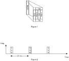
- FIG. 1 depicts one possible structure of the SSB for NR.
- the SSB is transmitted periodically, such as every 20 ms.
- Figure 2 depicts the SSB transmission repetition.
- the Physical Downlink Shared Channel (PDSCH SIB ) provides the remaining required parts of the minimum system information necessary for a radio network device to communicate with the network; however, the PDSCH SIB is not part of the SSB.
- the PDSCH SIB may be transmitted in resources indicated by PBCH.
- the sync signals are located in the six central resource blocks (RB) of a carrier, using a bandwidth of 1.08 MHz. Accordingly, any radio network device with a receiver bandwidth wider than that could perform network sync.
- the SSB may span 4.32 MHz for carrier frequencies below 6 GHZ, and may be substantially higher for carrier frequencies above 6 GHz.
- the PBCH may have a bandwidth up to 5 MHz. Thus, the SSB may be wider in bandwidth than the capabilities of many radio network devices that need to access it - particularly M2M and NB-loT devices.
- FIG. 3 depicts a block diagram of a typical narrowband radio network device receiver chain 10.
- the receiver chain 10 includes one or more antennas 12, a Low Noise Amplifier (LNA) 14, filters 16, a downconverting mixer 18, a Variable Gain Amplifier (VGA) 20, additional filters 22, and an Analog-to-Digital Converter (ADC) 24.
- LNA Low Noise Amplifier
- VGA Variable Gain Amplifier
- ADC Analog-to-Digital Converter
- LO local oscillator
- the LO signal is created from a crystal that generates a certain fundamental frequency.
- the open-loop LO frequency inaccuracy in a radio network device is on the order of 10 ppm for crystals below 50 MHz.
- the inaccuracy may be up to 50 ppm. Greater accuracy may be obtained by the use of higher quality crystals; however this substantially increases receiver cost.
- the PSS is designed to be detected with a frequency error, it is necessary for the radio network device to test different frequency error hypotheses by performing a grid search over possible frequency errors. Once a likely PSS is detected, the radio network device may continue to detect SSS and PBCH for further processing.
- a time domain signal f(t) may be frequency translated by multiplying the signal with a complex value e j 2 ⁇ f 0 t , where f 0 represents the amount of frequency translation to be done and t represents the sampling instants of the time signals.
- This relationship is also used to frequency-translate received and stored sub-band signal for assembly into a combined broadband signal, as further described herein.
- a radio network device having a narrowband receiver effectively receives a wideband sync signal by receiving and storing successive, narrowband, frequency-offset "slices," or sub-band signals, each of which span a temporal duration equal to the sync signal repetition period.
- ⁇ represents the ceiling rounding operation.
- Figure 4 depicts this process graphically. Initially, a first sub-band signal is received at a first frequency and over a predetermined time duration equal to the SSB repetition period. This sub-band signal is stored. The radio network device receiver then shifts its reception frequency and receives a second sub-band signal over a the same duration. The timing of the reception iterations is determined by the defined repetition rate of the SSB retransmission. After k such sweeps, the received sub-band signals are appropriately frequency-offset and combined, and the desired sync signal (having its full bandwidth) is detected from the combined signal. Network access using the sync signal is then attempted. In some embodiments, each sub-band signal will comprise an integer number of OFDM sub-carriers.
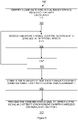
- FIG. 5 depicts the steps of a method 100, performed by a radio network device having a narrowband receiver, of receiving and processing a periodic, wideband network sync signal.
- the sync signal may be a PSS, SSS, TSS, or other periodic, wideband network sync signal.
- the sync "signal" may comprise a signal block, such as the SSB depicted in Figs. 1 and 2 .
- the radio network device identifies a candidate sync signal bandwidth and repetition pattern (block 102). This identification derives from an a priori known raster, which may be searched in a determined (or arbitrary) order; or it has been received from inter-frequency or inter-RAT handover signaling.
- the radio network device may also calculate the number k of receiving iterations required, based on the sync signal bandwidth f SSB and the receiver bandwidth f RX .
- the radio network device may initialize a counter value i .
- the radio network device receives and stores a sub-band of the sync signal bandwidth, over the duration of a sync signal repetition period.
- the sub-band signals may be configured such that their 3 dB bandwidths (for the upper and lower frequency edges) coincide. Other configurations may also be used, e.g., if a sync signal bandwidth may be covered with fewer sub-bands by using a wider distance, this may be a preferred solution in some cases.
- the sub-band signals are selected such that the combined power spectrum is optimally flat, but also other possible combinations are possible.
- the radio network device may increment the counter i .
- the radio network device repeats step 104 and reads another sub-band signal.
- the sub-band may be received in a specific order (e.g., sequentially) or in a random order, or in an order that is particularly preferable for the radio network device.
- combining the sub-band signals includes: upsampling each sub-band signal by zero padding and filtering such that each sub-band signal may resolve the full sync signal bandwidth; individually frequency translating each upsampled sub-band signal to a different position within the full sync signal bandwidth; and adding the translated, upsampled sub-band signals to generate a combined signal over the full sync signal bandwidth.
- the lower half of the sync signal portions are multiplied with a negative frequency and the upper half are multiplied with a positive frequency, as shown in Figure 5 .
- a bandwidth equal or larger than the full sync signal bandwidth is obtained.
- the frequency translations may be performed using the Fourier relationships described above.
- the combined signal is then processed to detect a sync signal.
- the combined signal may be correlated against a known a priori PSS (or other) sequence, such as a Z-C sequence.
- the radio network device attempts synchronization with the wireless communication network (block 110).
- PLL Phase Locked Loop
- This is performed by another frequency translation for the combined signal, where the translation corresponds to a hypothesized frequency error.
- the combination may also take time drift into account. Since the crystal oscillator driving the LO frequency may have some 10 ppm frequency error, this may also imply a time drift.
- the combined signal may include numerous combinations.
- Ts is the SSB sync period and X 1 and X 2 are the two different sub-band signals
- ⁇ may be a positive or negative number.
- the sequence may be interpolated from adjacent samples.
- a radio network device has no knowledge of the timing of SSB, other than its bandwidth (e.g., 4.32 MHz) and periodicity (e.g., 20 msec). If the radio network device did have at least some idea of where in time the SSB repetitions occur, it would time each of the k sweeps to begin/switch at the midpoint between SSB repetitions (or, indeed, reduce the duration of the sweep dramatically from the full 20 msec to just before and after the SSB). However, in general, the SSB could occur anywhere within the repetition period P SSB .
- the radio network device may decide to record each sub-band signal for longer than P SSB . This will ensure that the SSB is guaranteed to be contained in a sweep. However, the radio network device will then have to wait P SSB - t SSB between each sweep.
- the radio network device may continue by detecting, e.g., a secondary sync signal (SSS) or reading broadcast data (PBCH).
- SSS secondary sync signal
- PBCH broadcast data
- the radio network device may repeat block 110 of the method 100 with another frequency error hypothesis such that eventually a range of frequency errors, corresponding to the open loop inaccuracy of the crystal, have been explored and attempted.
- synchronization may not be possible, and the radio network device may repeat the entire method 100, using different assumptions for the SSB location.
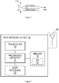
- FIG. 7 depicts a radio network device 30 having a narrowband receiver 10.
- a radio network device 30 is any type device capable of communicating with a network node and/or access point using radio signals.
- a radio network device 30 may therefore refer to a machine-to-machine (M2M) device, a machine-type communications (MTC) device, a Narrowband Internet of Things (NB loT) device, etc.
- M2M machine-to-machine
- MTC machine-type communications
- N loT Narrowband Internet of Things
- the radio network device 30 may also be a User Equipment (UE), such as a cellular telephone or "smartphone.”
- UE User Equipment
- a radio network device 30 may also be referred to as a radio device, a radio communication device, a radio network device, a wireless terminal, or simply a terminal - unless the context indicates otherwise, the use of any of these terms is intended to include device-to-device UEs or devices, machine-type devices, or devices capable of machine-to-machine communication, sensors equipped with a radio network device, wireless-enabled table computers, mobile terminals, smart phones, laptop-embedded equipped (LEE), laptop-mounted equipment (LME), USB dongles, wireless customer-premises equipment (CPE), etc.
- LOE laptop-embedded equipped
- LME laptop-mounted equipment
- CPE wireless customer-premises equipment
- M2M machine-to-machine
- MTC machine-type communication
- wireless sensor and sensor
- sensor may also be used. It should be understood that these devices may be UEs, but may be configured to transmit and/or receive data without direct human interaction.
- the radio network device 30 includes a user interface 32 (display, touchscreen, keyboard or keypad, microphone, speaker, and the like); in other embodiments, such as in many M2M, MTC, or NB loT scenarios, the radio network device 30 may include only a minimal, or no, user interface 32 (as indicated by the dashed lines of block 32 in Figure 8 ).
- the radio network device 30 also includes processing circuitry 34; memory 36; and radio circuits, such a transceiver 38, one or more antennas 40, and the like, to effect wireless communication across an air interface to one or more radio network nodes and/or access points.
- the antenna(s) 40 may protrude externally from the radio network device 30, or the antenna(s) 40 may be internal.
- the transceiver 38 may include the receiver 10 depicted in Figure 3 .
- Figure 8 depicts an embodiment in which the radio network device 30 is a UE 31.
- the UE 31 includes the same circuits and components described above.
- the UE 31 may include a sophisticated user interface 32, and may additionally include features such as a camera, accelerometer, satellite navigation signal receiver circuitry, vibrating motor, and the like (not depicted in Fig. 8 ).
- a particular UE 31 may include a receiver with a limited bandwidth, or which for various reasons (e.g., very strict control of power consumption in some modes) is operated only over a narrow bandwidth.
- the processing circuitry 34 may comprise any sequential state machine operative to execute machine instructions stored as machine-readable computer programs in memory 36, such as one or more hardware-implemented state machines (e.g., in discrete logic, FPGA, ASIC, etc.); programmable logic together with appropriate firmware; one or more stored-program, general-purpose processors, such as a microprocessor or Digital Signal Processor (DSP), or any combination of the above.
- state machines e.g., in discrete logic, FPGA, ASIC, etc.
- programmable logic e.g., in discrete logic, FPGA, ASIC, etc.
- firmware e.g., in discrete logic, FPGA, ASIC, etc.
- general-purpose processors such as a microprocessor or Digital Signal Processor (DSP), or any combination of the above.
- DSP Digital Signal Processor
- the memory 36 may comprise any non-transitory machine-readable media known in the art or that may be developed, including but not limited to magnetic media (e.g., floppy disc, hard disc drive, etc.), optical media (e.g., CD-ROM, DVD-ROM, etc.), solid state media (e.g., SRAM, DRAM, DDRAM, ROM, PROM, EPROM, Flash memory, solid state disc, etc.), or the like.
- magnetic media e.g., floppy disc, hard disc drive, etc.
- optical media e.g., CD-ROM, DVD-ROM, etc.
- solid state media e.g., SRAM, DRAM, DDRAM, ROM, PROM, EPROM, Flash memory, solid state disc, etc.
- the radio circuits may comprise one or more transceivers 38 used to communicate with one or more other transceivers via a Radio Access Network (RAN) according to one or more communication protocols known in the art or that may be developed, such as IEEE 802.xx, CDMA, WCDMA, GSM, LTE, UTRAN, WiMax, NB-loT, NR, or the like.
- the transceiver 38 implements transmitter and receiver functionality appropriate to the RAN links (e.g., frequency allocations and the like).
- the transmitter and receiver functions may share circuit components and/or software, or alternatively may be implemented separately.
- the memory 36 is operative to store, and the processing circuitry 34 operative to execute, software 42 which when executed is operative to cause the radio network device 30 to iteratively receive portions of a periodic, wideband sync signal, and assemble the portions to generate a combined sync signal with which to attempt network discovery.
- the software 42 when executed on the processing circuitry 34, is operative to perform the method 100 described and claimed herein. This allows the radio network device 30 having a narrowband receiver 10 to reliably receive and process wideband sync signals.
- FIG 9 illustrates example processing circuitry 34, such as that in the radio network device 30 of Figure 7 or the UE 31 of Figure 8 .
- the processing circuitry 34 comprises a plurality of physical units.
- the processing circuitry 34 comprises a candidate sync signal identifying unit 46, a sub-band signal receiving and storing unit 48, a sub-band signal combining unit 50, and a combined signal processing unit 52.
- the candidate sync signal identifying unit 46 is configured to identify a candidate sync signal bandwidth and repetition pattern.
- the sub-band signal receiving and storing unit 48 is configured to iteratively, for each of a plurality of sub-bands of the sync signal bandwidth, receive and store a signal over the duration of a sync signal repetition period.
- the sub-band signal combining unit 50 is configured to combine the plurality of sub-band signals to obtain combined signal over the full sync signal bandwidth.
- the combined signal processing unit 52 is configured to process the combined signal to detect a sync signal and attempt synchronization with a wireless communication network.
- Figure 10 illustrates example software 42, such as that in memory 36 in the radio network device 30 of Figure 8 or the UE 31 of Figure 9 .
- the software 42 comprises a plurality of software modules.
- the software 42 comprises a candidate sync signal identifying module 54, a sub-band signal receiving and storing module 56, a sub-band signal combining module 58, and a combined signal processing module 60.
- the candidate sync signal identifying module 54 is configured to identify a candidate sync signal bandwidth and repetition pattern.
- the sub-band signal receiving and storing module 56 is configured to iteratively, for each of a plurality of sub-bands of the sync signal bandwidth, receive and store a signal over the duration of a sync signal repetition period.
- the sub-band signal combining module 58 is configured to combine the plurality of sub-band signals to obtain combined signal over the full sync signal bandwidth.
- the combined signal processing module 60 is configured to process the combined signal to detect a sync signal and attempt synchronization with a wireless communication network.
- Embodiments of the present invention present numerous advantages over the prior art.
- a narrowband radio network device to receive and process a wideband sync signal, such as those proposed for NR.
- One of the major features of NR is support for massive numbers of simple, low-cost, narrowband M2M and NB-loT radio network devices.
- Embodiments of the present invention provide a methodology for these narrowband radio network devices to access wireless communication networks.
Landscapes
- Engineering & Computer Science (AREA)
- Computer Networks & Wireless Communication (AREA)
- Signal Processing (AREA)
- Mobile Radio Communication Systems (AREA)
- Synchronisation In Digital Transmission Systems (AREA)
Claims (12)
- Procédé (100), exécuté par un dispositif réseau radio (30) présentant un récepteur à bande étroite (38), de réception et de traitement d'un signal de synchronisation réseau, sync, périodique à large bande, le procédé comprenant les étapes consistant à :identifier (102) un modèle de répétition et de largeur de bande de signal de synchronisation candidat, dans lequel l'identification d'un modèle de répétition et de largeur de bande de signal de synchronisation candidat comprend l'obtention d'une position de signal de synchronisation candidate à partir d'une trame de synchronisation connue à priori ou l'obtention de la position de signal de synchronisation candidate via une signalisation de transfert ;de manière itérative, pour chacune d'une pluralité de sous-bandes de la largeur de bande du signal de synchronisation, recevoir et stocker (104) un signal sur la durée d'une période de répétition du signal de synchronisation ;combiner (108) la pluralité de signaux de sous-bandes pour obtenir un signal combiné sur la largeur de bande complète du signal de synchronisation ; ettraiter (110) le signal combiné pour détecter un signal de synchronisation et tenter une synchronisation avec un réseau de communication sans fil,caractérisé en ce que la combinaison de la pluralité de signaux de sous-bandes pour obtenir le signal combiné comprend les étapes consistant à :sur-échantillonner chaque signal de sous-bande par remplissage du zéro et filtrage de telle sorte que chaque signal de sous-bande s'adapte à la largeur de bande complète du signal de synchronisation ;convertir individuellement en fréquence chaque signal de sous-bande sur-échantillonné à une position différente dans la largeur de bande complète du signal de synchronisation ; etadditionner les signaux de sous-bande convertis et sur-échantillonnés pour générer un signal combiné sur toute la largeur de bande du signal de synchronisation.
- Procédé selon la revendication 1 dans lequel le nombre k de sous-bandes de la largeur de bande du signal de synchronisation est donné par

la largeur de bande du dispositif réseau radio, et ┌.┐ représente une opération d'arrondi de plafond. - Procédé selon l'une quelconque des revendications 1-2, dans lequel la réception et le stockage (104) de chaque signal de sous-bande comprennent la réception de chaque signal de sous-bande de telle sorte que les points de largeur de bande de 3 dB des extrémités de fréquence supérieure et inférieure de chaque sous-bande coïncident.
- Procédé selon l'une quelconque des revendications 1-3, dans lequel la réception et le stockage (104) de chaque signal de sous-bande comprennent la réception et le stockage de chaque signal de sous-bande dans un ordre séquentiel de fréquence.
- Procédé selon l'une quelconque des revendications 1-3, dans lequel la réception et le stockage (104) de chaque signal de sous-bande comprennent la réception et le stockage de chaque signal de sous-bande dans un ordre aléatoire.
- Procédé selon les revendications 1-5, dans lequel le sur-échantillonnage de chaque signal de sous-bande comprend un sur-échantillonnage k fois où k signaux de sous-bande sont reçus et stockés.
- Procédé selon les revendications 1-6, dans lequel la conversion en fréquence de chaque signal de sous-bande sur-échantillonné comprend la conversion en fréquence de la moitié des parties à une fréquence négative de sorte que la largeur de bande complète du signal de synchronisation est centrée sur la bande de base.
- Procédé selon l'une quelconque des revendications 1-7, dans lequel le traitement (110) du signal combiné pour détecter un signal de synchronisation et tenter une synchronisation avec un réseau de communication sans fil comprend la conversion en fréquence du signal combiné par une erreur de fréquence hypothétique avant la tentative de synchronisation avec le réseau.
- Procédé selon la revendication 8, dans lequel le traitement (110) du signal combiné comprend en outre la prise en compte de la dérive temporelle.
- Dispositif réseau radio (30), comprenant :une ou plusieurs antennes (40) ;un émetteur-récepteur (38) comprenant un circuit de réception à bande étroite ; etun circuit de traitement (34) connecté de manière opérationnelle à l'émetteur-récepteur et servant àidentifier (102) un modèle de répétition et de largeur de bande de signal de synchronisation candidat, dans lequel l'identification d'un modèle de répétition et de largeur de bande de signal de synchronisation candidat comprend l'obtention d'une position de signal de synchronisation candidate à partir d'une trame de synchronisation connue à priori ou l'obtention de la position de signal de synchronisation candidate via une signalisation de transfert ;de manière itérative, pour chacune d'une pluralité de sous-bandes de la largeur de bande du signal de synchronisation, recevoir et stocker (104) un signal sur la durée d'une période de répétition du signal de synchronisation ;combiner (108) la pluralité de signaux de sous-bandes pour obtenir un signal combiné sur la largeur de bande complète du signal de synchronisation ; ettraiter (110) le signal combiné pour détecter un signal de synchronisation et tenter une synchronisation avec un réseau de communication sans fil,caractérisé en ce que le circuit de traitement (34) est opérationnel pour combiner la pluralité de signaux de sous-bande pour obtenir le signal combiné au moyen des étapes suivantes :sur-échantillonner chaque signal de sous-bande par remplissage du zéro et filtrage de telle sorte que chaque signal de sous-bande s'adapte à la largeur de bande complète du signal de synchronisation ;convertir individuellement en fréquence chaque signal de sous-bande sur-échantillonné à une position différente dans la largeur de bande complète du signal de synchronisation ; etadditionner les signaux de sous-bande convertis et sur-échantillonnés pour générer un signal combiné sur toute la largeur de bande du signal de synchronisation.
- Dispositif selon la revendication 10, dans lequel le circuit de traitement est en outre opérationnel pour exécuter le procédé selon l'une quelconque des revendications 2-9.
- Dispositif selon la revendication 10 ou 11, dans lequel le dispositif réseau radio (30) est un équipement utilisateur UE (31).
Applications Claiming Priority (2)
| Application Number | Priority Date | Filing Date | Title |
|---|---|---|---|
| US201762476596P | 2017-03-24 | 2017-03-24 | |
| PCT/EP2018/055287 WO2018172044A1 (fr) | 2017-03-24 | 2018-03-05 | Réception d'un signal de synchronisation périodique à large bande dans un récepteur à bande étroite |
Publications (2)
| Publication Number | Publication Date |
|---|---|
| EP3602986A1 EP3602986A1 (fr) | 2020-02-05 |
| EP3602986B1 true EP3602986B1 (fr) | 2022-06-29 |
Family
ID=61569272
Family Applications (1)
| Application Number | Title | Priority Date | Filing Date |
|---|---|---|---|
| EP18708993.3A Active EP3602986B1 (fr) | 2017-03-24 | 2018-03-05 | Réception d'un signal de synchronisation périodique à large bande dans un récepteur à bande étroite |
Country Status (4)
| Country | Link |
|---|---|
| US (1) | US10813014B2 (fr) |
| EP (1) | EP3602986B1 (fr) |
| CN (1) | CN110447210A (fr) |
| WO (1) | WO2018172044A1 (fr) |
Families Citing this family (2)
| Publication number | Priority date | Publication date | Assignee | Title |
|---|---|---|---|---|
| WO2020258335A1 (fr) * | 2019-06-28 | 2020-12-30 | 北京小米移动软件有限公司 | Procédé et appareil de configuration de ressource de commande, procédé et appareil de détermination de ressource, dispositif de communication et support de stockage |
| CN113258977B (zh) * | 2020-02-10 | 2022-08-09 | 华为技术有限公司 | 一种通信的方法及装置 |
Family Cites Families (26)
| Publication number | Priority date | Publication date | Assignee | Title |
|---|---|---|---|---|
| US5272724A (en) * | 1991-05-03 | 1993-12-21 | Motorola, Inc. | Wideband signal synchronization |
| US5668837A (en) | 1993-10-14 | 1997-09-16 | Ericsson Inc. | Dual-mode radio receiver for receiving narrowband and wideband signals |
| US5917850A (en) | 1994-11-24 | 1999-06-29 | Canon Kabushiki Kaisha | Spread spectrum receiving apparatus |
| US5802461A (en) | 1996-09-16 | 1998-09-01 | Texas Instruments Incorporated | Apparatus and method for timing recovery in vestigial sibeband modulation |
| CA2363927C (fr) | 2000-11-28 | 2004-07-06 | Research In Motion Limited | Detecteur de signal de synchronisation et methode connexe |
| RU2278470C2 (ru) | 2003-11-03 | 2006-06-20 | Корпорация "САМСУНГ ЭЛЕКТРОНИКС Ко., Лтд." | Способ синхронизации радиосигнала |
| US7434150B1 (en) | 2004-03-03 | 2008-10-07 | Marvell Israel (M.I.S.L.) Ltd. | Methods, circuits, architectures, software and systems for determining a data transmission error and/or checking or confirming such error determinations |
| US7457231B2 (en) * | 2004-05-04 | 2008-11-25 | Qualcomm Incorporated | Staggered pilot transmission for channel estimation and time tracking |
| US7801227B2 (en) | 2006-04-14 | 2010-09-21 | Qualcomm Incorporated | Methods and apparatus related to composite beacon and wideband synchronization signaling |
| US8335196B2 (en) * | 2006-09-19 | 2012-12-18 | Qualcomm Incorporated | Accommodating wideband and narrowband communication devices |
| US8244183B2 (en) * | 2008-08-12 | 2012-08-14 | Qualcomm Incorporated | Concurrent sync channel searching |
| EP2638741A1 (fr) * | 2010-11-12 | 2013-09-18 | Telefonaktiebolaget LM Ericsson (PUBL) | Détermination d'une fréquence de cellule de réseau de communication mobile |
| US20120163508A1 (en) * | 2010-12-27 | 2012-06-28 | Motorola, Inc. | Subcarrier placement strategy for a multi-carrier signal |
| US8634288B2 (en) | 2011-06-01 | 2014-01-21 | Telefonaktiebolaget L M Ericsson (Publ) | Symbol FFT RACH processing methods and devices |
| KR102087608B1 (ko) * | 2011-08-11 | 2020-03-13 | 삼성전자주식회사 | 통신 시스템에서 물리 하향링크 제어 채널들의 확장을 위한 장치 및 방법 |
| US20150071258A1 (en) | 2013-09-11 | 2015-03-12 | Luca Sanguinetti | Random access algorithm for lte systems |
| CN103974408B (zh) | 2014-04-01 | 2017-09-15 | 宽兆科技(深圳)有限公司 | 一种基于Mesh网的OFDMA系统及控制方法 |
| US10326546B2 (en) * | 2014-09-19 | 2019-06-18 | Qualcomm Incorporated | Directional synchronization signals in wireless communications |
| US10200229B2 (en) | 2015-01-16 | 2019-02-05 | Telefonaktiebolaget Lm Ericsson (Publ) | Method and apparatus for extracting resource block from signal |
| US20160337105A1 (en) | 2015-05-14 | 2016-11-17 | Interdigital Technology Corporation | Channel and noise estimation for downlink lte |
| US11212760B2 (en) | 2015-09-24 | 2021-12-28 | Qualcomm Incorporated | Common synchronization channel design for narrowband communications |
| US10285144B2 (en) | 2015-11-05 | 2019-05-07 | Qualcomm Incorporated | Clean-slate synchronization signal design and cell search algorithms |
| KR102153077B1 (ko) | 2016-04-20 | 2020-09-07 | 콘비다 와이어리스, 엘엘씨 | 다운링크 동기화 |
| WO2018073683A1 (fr) | 2016-10-10 | 2018-04-26 | Nokia Technologies Oy | Synchronisation d'équipement utilisateur à bande étroite et à large bande |
| US11019584B2 (en) * | 2017-03-14 | 2021-05-25 | Qualcomm Incorporated | User equipment operation in bandwidth narrower than synchronization signal bandwidth |
| US10079705B1 (en) | 2017-03-20 | 2018-09-18 | Samsung Electronics Co., Ltd. | Synchronization for low-energy long-range communications |
-
2018
- 2018-03-05 EP EP18708993.3A patent/EP3602986B1/fr active Active
- 2018-03-05 CN CN201880019240.2A patent/CN110447210A/zh active Pending
- 2018-03-05 US US15/781,612 patent/US10813014B2/en active Active
- 2018-03-05 WO PCT/EP2018/055287 patent/WO2018172044A1/fr not_active Ceased
Also Published As
| Publication number | Publication date |
|---|---|
| WO2018172044A1 (fr) | 2018-09-27 |
| US20190141587A1 (en) | 2019-05-09 |
| CN110447210A (zh) | 2019-11-12 |
| US10813014B2 (en) | 2020-10-20 |
| EP3602986A1 (fr) | 2020-02-05 |
Similar Documents
| Publication | Publication Date | Title |
|---|---|---|
| CN111869292B (zh) | 用于非授权频谱的无线通信方法和设备 | |
| US9930656B2 (en) | Cell search and synchronization in millimeter-wave capable small cells | |
| US10034253B2 (en) | Cell search procedure frame format | |
| EP3923665B1 (fr) | Procédé de transmission de données, dispositif terminal et dispositif de réseau | |
| CN112534886A (zh) | 传输信号的方法、终端设备和网络设备 | |
| US20160142241A1 (en) | Cell Search Procedure Frame Format | |
| CN107534845B (zh) | 无线通信系统中的无线装置和网络节点以及同步方法 | |
| US12593297B2 (en) | Location estimation for reduced capacity devices | |
| US20240056242A1 (en) | Frequency Hopped PRSs for Location Estimation of Reduced Capacity Devices | |
| US12309088B2 (en) | PRS muting for location estimation of reduced capacity devices | |
| CN111165046A (zh) | 传输信息的方法和设备 | |
| CN112534906A (zh) | 通信方法、终端设备和网络设备 | |
| EP3602986B1 (fr) | Réception d'un signal de synchronisation périodique à large bande dans un récepteur à bande étroite | |
| CN106161314A (zh) | 无线信号干扰方法及装置 | |
| CN113728701A (zh) | 用于发送上行信道/信号的方法、终端设备和网络设备 | |
| US11071077B2 (en) | Radio (NR) wideband sync detection | |
| US20230292207A1 (en) | Fast transitions between radio access technologies (rats) based on energy thresholds | |
| KR102809657B1 (ko) | 무선 통신에서의 동기화 신호 및 물리적 브로드캐스트 채널 블록 송신 | |
| US20240056771A1 (en) | Reference Signal Configuration for Location Estimation of Reduced Capacity Devices | |
| CN121312210A (zh) | 用于解决上行链路子带与同步信号块符号之间的冲突的方法和装置 | |
| HK1258339A1 (zh) | 信号传输的方法、网络设备和终端设备 | |
| HK1258339B (en) | Signal transmission method, network device, and terminal device |
Legal Events
| Date | Code | Title | Description |
|---|---|---|---|
| STAA | Information on the status of an ep patent application or granted ep patent |
Free format text: STATUS: UNKNOWN |
|
| STAA | Information on the status of an ep patent application or granted ep patent |
Free format text: STATUS: THE INTERNATIONAL PUBLICATION HAS BEEN MADE |
|
| PUAI | Public reference made under article 153(3) epc to a published international application that has entered the european phase |
Free format text: ORIGINAL CODE: 0009012 |
|
| STAA | Information on the status of an ep patent application or granted ep patent |
Free format text: STATUS: REQUEST FOR EXAMINATION WAS MADE |
|
| 17P | Request for examination filed |
Effective date: 20191008 |
|
| AK | Designated contracting states |
Kind code of ref document: A1 Designated state(s): AL AT BE BG CH CY CZ DE DK EE ES FI FR GB GR HR HU IE IS IT LI LT LU LV MC MK MT NL NO PL PT RO RS SE SI SK SM TR |
|
| AX | Request for extension of the european patent |
Extension state: BA ME |
|
| DAV | Request for validation of the european patent (deleted) | ||
| DAX | Request for extension of the european patent (deleted) | ||
| STAA | Information on the status of an ep patent application or granted ep patent |
Free format text: STATUS: EXAMINATION IS IN PROGRESS |
|
| 17Q | First examination report despatched |
Effective date: 20210312 |
|
| GRAP | Despatch of communication of intention to grant a patent |
Free format text: ORIGINAL CODE: EPIDOSNIGR1 |
|
| STAA | Information on the status of an ep patent application or granted ep patent |
Free format text: STATUS: GRANT OF PATENT IS INTENDED |
|
| INTG | Intention to grant announced |
Effective date: 20220323 |
|
| GRAS | Grant fee paid |
Free format text: ORIGINAL CODE: EPIDOSNIGR3 |
|
| GRAA | (expected) grant |
Free format text: ORIGINAL CODE: 0009210 |
|
| STAA | Information on the status of an ep patent application or granted ep patent |
Free format text: STATUS: THE PATENT HAS BEEN GRANTED |
|
| AK | Designated contracting states |
Kind code of ref document: B1 Designated state(s): AL AT BE BG CH CY CZ DE DK EE ES FI FR GB GR HR HU IE IS IT LI LT LU LV MC MK MT NL NO PL PT RO RS SE SI SK SM TR |
|
| REG | Reference to a national code |
Ref country code: CH Ref legal event code: EP |
|
| REG | Reference to a national code |
Ref country code: AT Ref legal event code: REF Ref document number: 1502045 Country of ref document: AT Kind code of ref document: T Effective date: 20220715 |
|
| REG | Reference to a national code |
Ref country code: IE Ref legal event code: FG4D |
|
| REG | Reference to a national code |
Ref country code: DE Ref legal event code: R096 Ref document number: 602018037282 Country of ref document: DE |
|
| REG | Reference to a national code |
Ref country code: NL Ref legal event code: FP |
|
| REG | Reference to a national code |
Ref country code: LT Ref legal event code: MG9D |
|
| PG25 | Lapsed in a contracting state [announced via postgrant information from national office to epo] |
Ref country code: SE Free format text: LAPSE BECAUSE OF FAILURE TO SUBMIT A TRANSLATION OF THE DESCRIPTION OR TO PAY THE FEE WITHIN THE PRESCRIBED TIME-LIMIT Effective date: 20220629 Ref country code: NO Free format text: LAPSE BECAUSE OF FAILURE TO SUBMIT A TRANSLATION OF THE DESCRIPTION OR TO PAY THE FEE WITHIN THE PRESCRIBED TIME-LIMIT Effective date: 20220929 Ref country code: LT Free format text: LAPSE BECAUSE OF FAILURE TO SUBMIT A TRANSLATION OF THE DESCRIPTION OR TO PAY THE FEE WITHIN THE PRESCRIBED TIME-LIMIT Effective date: 20220629 Ref country code: HR Free format text: LAPSE BECAUSE OF FAILURE TO SUBMIT A TRANSLATION OF THE DESCRIPTION OR TO PAY THE FEE WITHIN THE PRESCRIBED TIME-LIMIT Effective date: 20220629 Ref country code: GR Free format text: LAPSE BECAUSE OF FAILURE TO SUBMIT A TRANSLATION OF THE DESCRIPTION OR TO PAY THE FEE WITHIN THE PRESCRIBED TIME-LIMIT Effective date: 20220930 Ref country code: FI Free format text: LAPSE BECAUSE OF FAILURE TO SUBMIT A TRANSLATION OF THE DESCRIPTION OR TO PAY THE FEE WITHIN THE PRESCRIBED TIME-LIMIT Effective date: 20220629 Ref country code: BG Free format text: LAPSE BECAUSE OF FAILURE TO SUBMIT A TRANSLATION OF THE DESCRIPTION OR TO PAY THE FEE WITHIN THE PRESCRIBED TIME-LIMIT Effective date: 20220929 |
|
| REG | Reference to a national code |
Ref country code: AT Ref legal event code: MK05 Ref document number: 1502045 Country of ref document: AT Kind code of ref document: T Effective date: 20220629 |
|
| PG25 | Lapsed in a contracting state [announced via postgrant information from national office to epo] |
Ref country code: RS Free format text: LAPSE BECAUSE OF FAILURE TO SUBMIT A TRANSLATION OF THE DESCRIPTION OR TO PAY THE FEE WITHIN THE PRESCRIBED TIME-LIMIT Effective date: 20220629 Ref country code: LV Free format text: LAPSE BECAUSE OF FAILURE TO SUBMIT A TRANSLATION OF THE DESCRIPTION OR TO PAY THE FEE WITHIN THE PRESCRIBED TIME-LIMIT Effective date: 20220629 |
|
| PG25 | Lapsed in a contracting state [announced via postgrant information from national office to epo] |
Ref country code: SM Free format text: LAPSE BECAUSE OF FAILURE TO SUBMIT A TRANSLATION OF THE DESCRIPTION OR TO PAY THE FEE WITHIN THE PRESCRIBED TIME-LIMIT Effective date: 20220629 Ref country code: SK Free format text: LAPSE BECAUSE OF FAILURE TO SUBMIT A TRANSLATION OF THE DESCRIPTION OR TO PAY THE FEE WITHIN THE PRESCRIBED TIME-LIMIT Effective date: 20220629 Ref country code: RO Free format text: LAPSE BECAUSE OF FAILURE TO SUBMIT A TRANSLATION OF THE DESCRIPTION OR TO PAY THE FEE WITHIN THE PRESCRIBED TIME-LIMIT Effective date: 20220629 Ref country code: PT Free format text: LAPSE BECAUSE OF FAILURE TO SUBMIT A TRANSLATION OF THE DESCRIPTION OR TO PAY THE FEE WITHIN THE PRESCRIBED TIME-LIMIT Effective date: 20221031 Ref country code: ES Free format text: LAPSE BECAUSE OF FAILURE TO SUBMIT A TRANSLATION OF THE DESCRIPTION OR TO PAY THE FEE WITHIN THE PRESCRIBED TIME-LIMIT Effective date: 20220629 Ref country code: EE Free format text: LAPSE BECAUSE OF FAILURE TO SUBMIT A TRANSLATION OF THE DESCRIPTION OR TO PAY THE FEE WITHIN THE PRESCRIBED TIME-LIMIT Effective date: 20220629 Ref country code: AT Free format text: LAPSE BECAUSE OF FAILURE TO SUBMIT A TRANSLATION OF THE DESCRIPTION OR TO PAY THE FEE WITHIN THE PRESCRIBED TIME-LIMIT Effective date: 20220629 |
|
| PG25 | Lapsed in a contracting state [announced via postgrant information from national office to epo] |
Ref country code: PL Free format text: LAPSE BECAUSE OF FAILURE TO SUBMIT A TRANSLATION OF THE DESCRIPTION OR TO PAY THE FEE WITHIN THE PRESCRIBED TIME-LIMIT Effective date: 20220629 Ref country code: IS Free format text: LAPSE BECAUSE OF FAILURE TO SUBMIT A TRANSLATION OF THE DESCRIPTION OR TO PAY THE FEE WITHIN THE PRESCRIBED TIME-LIMIT Effective date: 20221029 |
|
| REG | Reference to a national code |
Ref country code: DE Ref legal event code: R097 Ref document number: 602018037282 Country of ref document: DE |
|
| PG25 | Lapsed in a contracting state [announced via postgrant information from national office to epo] |
Ref country code: AL Free format text: LAPSE BECAUSE OF FAILURE TO SUBMIT A TRANSLATION OF THE DESCRIPTION OR TO PAY THE FEE WITHIN THE PRESCRIBED TIME-LIMIT Effective date: 20220629 |
|
| PG25 | Lapsed in a contracting state [announced via postgrant information from national office to epo] |
Ref country code: DK Free format text: LAPSE BECAUSE OF FAILURE TO SUBMIT A TRANSLATION OF THE DESCRIPTION OR TO PAY THE FEE WITHIN THE PRESCRIBED TIME-LIMIT Effective date: 20220629 Ref country code: CZ Free format text: LAPSE BECAUSE OF FAILURE TO SUBMIT A TRANSLATION OF THE DESCRIPTION OR TO PAY THE FEE WITHIN THE PRESCRIBED TIME-LIMIT Effective date: 20220629 |
|
| PLBE | No opposition filed within time limit |
Free format text: ORIGINAL CODE: 0009261 |
|
| STAA | Information on the status of an ep patent application or granted ep patent |
Free format text: STATUS: NO OPPOSITION FILED WITHIN TIME LIMIT |
|
| 26N | No opposition filed |
Effective date: 20230330 |
|
| PG25 | Lapsed in a contracting state [announced via postgrant information from national office to epo] |
Ref country code: SI Free format text: LAPSE BECAUSE OF FAILURE TO SUBMIT A TRANSLATION OF THE DESCRIPTION OR TO PAY THE FEE WITHIN THE PRESCRIBED TIME-LIMIT Effective date: 20220629 |
|
| PG25 | Lapsed in a contracting state [announced via postgrant information from national office to epo] |
Ref country code: MC Free format text: LAPSE BECAUSE OF FAILURE TO SUBMIT A TRANSLATION OF THE DESCRIPTION OR TO PAY THE FEE WITHIN THE PRESCRIBED TIME-LIMIT Effective date: 20220629 |
|
| REG | Reference to a national code |
Ref country code: CH Ref legal event code: PL |
|
| REG | Reference to a national code |
Ref country code: BE Ref legal event code: MM Effective date: 20230331 |
|
| PG25 | Lapsed in a contracting state [announced via postgrant information from national office to epo] |
Ref country code: LU Free format text: LAPSE BECAUSE OF NON-PAYMENT OF DUE FEES Effective date: 20230305 |
|
| REG | Reference to a national code |
Ref country code: IE Ref legal event code: MM4A |
|
| PG25 | Lapsed in a contracting state [announced via postgrant information from national office to epo] |
Ref country code: LI Free format text: LAPSE BECAUSE OF NON-PAYMENT OF DUE FEES Effective date: 20230331 Ref country code: IT Free format text: LAPSE BECAUSE OF FAILURE TO SUBMIT A TRANSLATION OF THE DESCRIPTION OR TO PAY THE FEE WITHIN THE PRESCRIBED TIME-LIMIT Effective date: 20220629 Ref country code: IE Free format text: LAPSE BECAUSE OF NON-PAYMENT OF DUE FEES Effective date: 20230305 Ref country code: FR Free format text: LAPSE BECAUSE OF NON-PAYMENT OF DUE FEES Effective date: 20230331 Ref country code: CH Free format text: LAPSE BECAUSE OF NON-PAYMENT OF DUE FEES Effective date: 20230331 |
|
| PG25 | Lapsed in a contracting state [announced via postgrant information from national office to epo] |
Ref country code: BE Free format text: LAPSE BECAUSE OF NON-PAYMENT OF DUE FEES Effective date: 20230331 |
|
| PG25 | Lapsed in a contracting state [announced via postgrant information from national office to epo] |
Ref country code: BG Free format text: LAPSE BECAUSE OF FAILURE TO SUBMIT A TRANSLATION OF THE DESCRIPTION OR TO PAY THE FEE WITHIN THE PRESCRIBED TIME-LIMIT Effective date: 20220629 |
|
| PG25 | Lapsed in a contracting state [announced via postgrant information from national office to epo] |
Ref country code: BG Free format text: LAPSE BECAUSE OF FAILURE TO SUBMIT A TRANSLATION OF THE DESCRIPTION OR TO PAY THE FEE WITHIN THE PRESCRIBED TIME-LIMIT Effective date: 20220629 |
|
| PG25 | Lapsed in a contracting state [announced via postgrant information from national office to epo] |
Ref country code: CY Free format text: LAPSE BECAUSE OF FAILURE TO SUBMIT A TRANSLATION OF THE DESCRIPTION OR TO PAY THE FEE WITHIN THE PRESCRIBED TIME-LIMIT; INVALID AB INITIO Effective date: 20180305 |
|
| PG25 | Lapsed in a contracting state [announced via postgrant information from national office to epo] |
Ref country code: HU Free format text: LAPSE BECAUSE OF FAILURE TO SUBMIT A TRANSLATION OF THE DESCRIPTION OR TO PAY THE FEE WITHIN THE PRESCRIBED TIME-LIMIT; INVALID AB INITIO Effective date: 20180305 |
|
| PG25 | Lapsed in a contracting state [announced via postgrant information from national office to epo] |
Ref country code: TR Free format text: LAPSE BECAUSE OF FAILURE TO SUBMIT A TRANSLATION OF THE DESCRIPTION OR TO PAY THE FEE WITHIN THE PRESCRIBED TIME-LIMIT Effective date: 20220629 |
|
| PGFP | Annual fee paid to national office [announced via postgrant information from national office to epo] |
Ref country code: GB Payment date: 20260327 Year of fee payment: 9 |
|
| PGFP | Annual fee paid to national office [announced via postgrant information from national office to epo] |
Ref country code: DE Payment date: 20260327 Year of fee payment: 9 |
|
| PGFP | Annual fee paid to national office [announced via postgrant information from national office to epo] |
Ref country code: NL Payment date: 20260326 Year of fee payment: 9 |