EP3603365A1 - Selbstfahrendes fahrzeug zum zermahlen des bodens - Google Patents
Selbstfahrendes fahrzeug zum zermahlen des bodens Download PDFInfo
- Publication number
- EP3603365A1 EP3603365A1 EP19180958.1A EP19180958A EP3603365A1 EP 3603365 A1 EP3603365 A1 EP 3603365A1 EP 19180958 A EP19180958 A EP 19180958A EP 3603365 A1 EP3603365 A1 EP 3603365A1
- Authority
- EP
- European Patent Office
- Prior art keywords
- milling machine
- nozzles
- self
- propelled vehicle
- nitrogen
- Prior art date
- Legal status (The legal status is an assumption and is not a legal conclusion. Google has not performed a legal analysis and makes no representation as to the accuracy of the status listed.)
- Withdrawn
Links
Images



Classifications
-
- A—HUMAN NECESSITIES
- A01—AGRICULTURE; FORESTRY; ANIMAL HUSBANDRY; HUNTING; TRAPPING; FISHING
- A01B—SOIL WORKING IN AGRICULTURE OR FORESTRY; PARTS, DETAILS, OR ACCESSORIES OF AGRICULTURAL MACHINES OR IMPLEMENTS, IN GENERAL
- A01B33/00—Tilling implements with rotary driven tools, e.g. in combination with fertiliser distributors or seeders, with grubbing chains, with sloping axles, with driven discs
- A01B33/16—Tilling implements with rotary driven tools, e.g. in combination with fertiliser distributors or seeders, with grubbing chains, with sloping axles, with driven discs with special additional arrangements
-
- E—FIXED CONSTRUCTIONS
- E01—CONSTRUCTION OF ROADS, RAILWAYS, OR BRIDGES
- E01C—CONSTRUCTION OF, OR SURFACES FOR, ROADS, SPORTS GROUNDS, OR THE LIKE; MACHINES OR AUXILIARY TOOLS FOR CONSTRUCTION OR REPAIR
- E01C23/00—Auxiliary devices or arrangements for constructing, repairing, reconditioning, or taking-up road or like surfaces
- E01C23/06—Devices or arrangements for working the finished surface; Devices for repairing or reconditioning the surface of damaged paving; Recycling in place or on the road
- E01C23/08—Devices or arrangements for working the finished surface; Devices for repairing or reconditioning the surface of damaged paving; Recycling in place or on the road for roughening or patterning; for removing the surface down to a predetermined depth high spots or material bonded to the surface, e.g. markings; for maintaining earth roads, clay courts or like surfaces by means of surface working tools, e.g. scarifiers, levelling blades
- E01C23/085—Devices or arrangements for working the finished surface; Devices for repairing or reconditioning the surface of damaged paving; Recycling in place or on the road for roughening or patterning; for removing the surface down to a predetermined depth high spots or material bonded to the surface, e.g. markings; for maintaining earth roads, clay courts or like surfaces by means of surface working tools, e.g. scarifiers, levelling blades using power-driven tools, e.g. vibratory tools
- E01C23/088—Rotary tools, e.g. milling drums
-
- A—HUMAN NECESSITIES
- A01—AGRICULTURE; FORESTRY; ANIMAL HUSBANDRY; HUNTING; TRAPPING; FISHING
- A01B—SOIL WORKING IN AGRICULTURE OR FORESTRY; PARTS, DETAILS, OR ACCESSORIES OF AGRICULTURAL MACHINES OR IMPLEMENTS, IN GENERAL
- A01B27/00—Clod-crushers
Definitions
- This invention relates to a self-propelled vehicle for grinding ground, and more precisely a self-propelled vehicle for grinding stony and rocky ground, for the purpose of making it usable for agriculture.
- both the accessory equipment for tractors, and the self-propelled vehicles developed up to now, are capable of grinding only relatively soft ground, such as road paving or earths containing both soil and stones.
- both the equipment and the vehicles currently for sale are not usable for grinding ground which is rocky (that is to say, not constituted of stones mixed with soil, but of extensive rocky formations) or extremely stony (large stones or complete or almost complete absence of soil).
- the equipment and vehicles currently for sale are not capable of doing it in acceptable times and with reasonable operating costs.
- the grinding heads are made of metal alloys with high mechanical resistance and comprise a fixed part fixed to the rotary drum of the milling machine, and an operating part which is joined to the fixed part and which can easily be substituted once worn. If the material to be ground up is particularly hard or compact, the operating parts of the heads tend to wear very quickly, until the grinding operations basically become uneconomical.
- a further problem which may arise with prior art milling machines, is the risk that the high temperatures which may be reached due to the friction between the milling machine and the ground, cause self-combustion of any combustible materials which are present inside the milling machine and, consequently, the development of bursts of flame or even explosions.
- the technical purpose which forms the basis of this invention is to provide a self-propelled vehicle for grinding ground which overcomes the above-mentioned disadvantages.
- the technical purpose of this invention is to provide a self-propelled vehicle for grinding ground, which allows grinding with good efficiency and with reasonable working times, even of rocky or extremely stony earths.
- a further technical purpose of this invention is to provide a self-propelled vehicle for grinding ground, which minimises the risk of explosions or bursts of flame.
- the numeral 1 denotes in its entirety a self-propelled vehicle made according to this invention. It should be noticed that, irrespective of the content of the claims appended to this patent application, the Applicant as of now reserves the right to file any patent applications claiming the priority of this, or divisional applications, which even have as their subject matter only one of the innovative aspects described below. In fact, each innovative aspect of the self-propelled vehicle 1, described below shall be understood as a possible subject of independent protection even not in combination with the other innovative aspects described.
- the self-propelled vehicle 1 comprises first a supporting carriage 2 which may be equipped with wheels and/or tracks 3.
- the bottoms of the wheels and/or tracks 3 with which the supporting carriage 2 is equipped define a resting plane 4 for the supporting carriage 2 on the earth, a resting plane 4 which is horizontal in the case of flat earth.
- the wheels and/or tracks 3 identify the straight line of travel of the supporting carriage 2 on the earth (line parallel to the longitudinal line of extension of the self-propelled vehicle 1).
- the supporting carriage 2 supports cantilever-style a milling machine 5 suitable for grinding the ground.
- the milling machine 5 is supported by a supporting arm 6 hinged to the supporting carriage 2, and by two hydraulic actuators 7 suitable for positioning the milling machine 5 in the desired operating position, by making the supporting arm 6 rotate.
- the milling machine 5 must be positioned in such a way that it projects below the resting plane 4 defined by the wheels and/or tracks 3, by a height equal to the depth to which the earth is to be worked ( Figure 1 - in the preferred embodiment the milling machine 5 is able to project by at least 50 cm, preferably by at least 60 cm, below the resting plane 4).
- the connection of the milling machine 5 to the supporting arm 6, and its movement relative to the latter may even be obtained with any other technical solution suitable for the purpose.
- the milling machine 5 it is even possible for the milling machine 5 to be positioned at the rear of the supporting carriage 2, as well as at an intermediate portion of it (in that case it will not be supported cantilever-style).
- the milling machine 5 also comprises a drum 8 (advantageously having a cylindrical section), equipped with a plurality of grinding heads 9 which are evenly distributed on its outer surface.
- the drum 8 is also rotatable about its own central axis 10, which is positioned perpendicular to the straight line of travel of the self-propelled vehicle 1 and parallel to the resting plane 4 (in other words the central axis 10 is horizontal and transversal when the ground on which the vehicle rests is flat).
- At least one motor 11 (there may be more than one for the various functionalities of the vehicle) which is connected both to the drum 8 of the milling machine 5, for driving its rotation about the central axis 10, and to the wheels and/or to the tracks 3, for driving them and therefore making the supporting carriage 2 advance on the earth.
- a containment housing 12 also partly surrounds the milling machine 5. That containment housing 12 is closed at the side and at the top, whilst it is open at the bottom for allowing the milling machine 5 to project downward.
- the lower middle of the containment housing 12 is also equipped with a lifting system relative to the milling machine 5, both at the front and at the rear. That lifting system allow varying of the lower projection of the milling machine 5 relative to the containment housing, allowing both varying of the working depth, and varying of the material outfeed time.
- front and rear relate to the line of advancing of the self-propelled vehicle 1 during operation
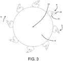
- each grinding head 9 of the milling machine 5 comprises a supporting part 15, connected to the drum 8, and an operating part 16 which is removably joined to the supporting part 15 in such a way that it is also free to rotate about its own axis of rotation 17 ( Figures 3 and 4 ).
- the operating part 16 of each grinding head 9 has a main axis of extension which coincides with the relative axis of rotation 17, and which is sloping forward relative to a direction of rotation of the milling machine 5 (indicated by the arrow R in Figure 3 ) so that, during the rotation, the tip of the operating part 16 is always angularly further forward than the coupling zone 18 between the supporting part 15 and the operating part 16.
- the inclination of the central axis 10 is understood relative to a line coming out of the central axis 10 which lies in the same plane radial to the central axis 10, of the milling machine 5 in which the main axis of extension lies.
- a washer 160 interposed between the movable operating part 16 and the supporting part 15 there is a washer 160 which is in turn free to rotate about the axis of rotation 17 both relative to the supporting part 15, and relative to the operating part 16.
- both the operating part 16 and the washer 160 are able to perform oscillations along the axis of rotation 17 relative to the supporting part 15.
- the grinding action is guaranteed both by the impact of the grinding heads 9 on the ground, and by the combined action of the self-same grinding heads 9 and of the containment housing 12, which has an inner containment wall 19 which is facing the milling machine 5 and which acts as a fixed contact element for the action of the grinding heads 9.
- the inner containment wall 19 has an upper portion 20 in the shape of a half-cylinder (with circular or polygonal section) and coaxial with the central axis 10 of the drum 8, to which there are connected a front flat wall 21 and a rear flat wall 22, whose bottoms respectively define part of the front edge 13 and part of the rear edge 14 of the containment housing 12.
- the containment housing 12 may also comprise an outer wall 23, and a hollow space 24 between the inner containment wall 19 and the outer wall 23 (the hollow space 24 may house part of the hydraulic/pneumatic circuits described below).
- the self-propelled vehicle 1 comprises a plurality of first nozzles 25 mounted in the containment housing 12 and facing the milling machine 5, and a chilled water feeding device 26 connected to the first nozzles 25.
- the milling machine 5 is constantly sprayed with chilled water in such a way as to keep the temperature of the operating parts of the grinding heads 9 relatively low, thereby ensuring that they last longer than in conventional milling machines.
- the first nozzles 25 are nebulising nozzles for improving the efficiency of heat exchange between the water and the grinding heads 9.
- the self-propelled vehicle 1 comprises a nitrogen feeding device 27, and a plurality of second nozzles 28, which are connected to the nitrogen feeding device 27 and positioned in such away as to supply nitrogen between the containment housing 12 and the milling machine 5.
- the second nozzles 28 may be fixed either to the containment housing 12, or to the rotary drum 8 (the latter solution is particularly advantageous if a solution according to the third innovative aspect described below is adopted).
- the containment housing 12 it is also preferable for the containment housing 12 to be made in such a way that is prevents or at least hinders the upward emission of nitrogen.
- At least several of the second nozzles 28 are constituted of first nozzles 25 and the self-propelled vehicle 1 comprises both the chilled water feeding device 26, and the nitrogen feeding device 27.
- at least several of the first nozzles 25, advantageously all of them, are simultaneously connected both to the chilled water feeding device 26, and to the nitrogen feeding device 27, for being fed with a mixture of chilled water and nitrogen.
- the inner containment wall 19 has a recess 29, which extends away from the milling machine 5, and in which the nozzle 25, 28 is mounted in such a way as to be protected from the material which during use moves with a whirling motion between the containment housing 12 and the milling machine 5.
- all or several of the second nozzles 28 may be joined to the drum 8 rather than to the containment housing 12.
- several second nozzles 28 may be joined to the drum 8 when in the vehicle the third innovative aspect described below is also adopted and, also in relation to that, nitrogen is used.
- the chilled water feeding device 26 comprises first a water source which may be constituted of at least one first tank or of a connection for connecting to a water supply network.
- a water source which may be constituted of at least one first tank or of a connection for connecting to a water supply network.
- the former solution is certainly preferable in the case of limited water consumption and absence of water supply networks, the latter solution may be advantageous where the earth to be treated is already equipped with a water supply network for irrigation.
- the water feeding device also comprises a first feeding pipe connected between the water source and the first nozzles 25, if necessary a pump joined to the first pipe for pumping water from the water source to the first nozzles 25 (unless flow rate and pressure necessary are guaranteed by an external water supply network), and a refrigerating unit (such as a chiller) mounted along the first pipe and suitable for chilling the water, advantageously bringing it to a temperature close to 0°C (advantageously the water temperature will be kept in the range 2°C ⁇ 2°C).
- a refrigerating unit such as a chiller mounted along the first pipe and suitable for chilling the water, advantageously bringing it to a temperature close to 0°C (advantageously the water temperature will be kept in the range 2°C ⁇ 2°C).
- the nitrogen feeding device 27 comprises a nitrogen source and a second pipe connected between the nitrogen source and the second nozzles 28.
- the nitrogen source may be constituted either of a second tank suitable for containing liquid nitrogen, or of a nitrogen generator suitable for extracting nitrogen from the ambient air.
- the self-propelled vehicle 1 is also equipped with a plurality of third nozzles 30 which are also mounted in the containment housing 12, and with a device 31 for feeding a further inert gas, having a specific weight lower than that of nitrogen (in particular, use of helium is provided for), connected to the third nozzles 30 ( Figure 5 ).
- the third nozzles 30 are in particular positioned at a height lower than the second nozzles 28 joined to the containment housing 12, are also facing the milling machine 5 and are distributed in the containment housing 12 along the whole axial extent of the along the whole axial extent of the milling machine 5 (similarly to what is shown in Figure 6 for the first nozzles 25), on both sides of the milling machine 5 in such a way as to attempt to always keep a layer of the inert gas below the layer of nitrogen.
- the third nozzles 30 are also advantageously mounted in recesses 29 made in the inner containment wall 19.
- the third innovative aspect of this invention is applied in the case in which at least several grinding heads 9 comprise the supporting part 15 and the rotatable operating part 16.
- the nozzle 32 is positioned recessed relative to the rest of the grinding head 9 so that it is more protected from the material which in use is being worked in the milling machine.
- the self-propelled vehicle 1 also comprises a device 33 for feeding a high pressure gaseous fluid (advantageously meaning at a pressure greater than or equal to 14 bar) to each pneumatic nozzle 32, and each pneumatic nozzle 32, in use, directs the high pressure gaseous fluid towards the coupling zone 18.
- each pneumatic nozzle 32 has a transit opening with a diameter of between 1 and 2 mm.
- the pneumatic nozzle 32 is advantageously positioned in such a way that the high pressure gaseous flow, supplied from it, strikes the side of the washer 160 facing the supporting part 15, generating on it a thrust away from the supporting part 15.
- the thrust must also be strong enough to move the washer 160 and the operating part 16 away from the supporting part 15 in the absence of other stresses.
- the operating part 16 and the washer 160 will perform a plurality of oscillations relative to the axis of rotation 17, caused by the alternating action of the gaseous flow (coming out of the grinding head 9) and the mechanical action applied on the ground and on the material present in the milling machine (going inward relative to the grinding head 9).
- the washer 160 is advantageously shaped in such a way as to define a sort of blading which, under the action of the pressurised gaseous fluid, is suitable for making the washer 160 rotate about the axis of rotation. Therefore, with each oscillation relative to the axis of rotation 17, the washer 160 also performs a rotation about the axis of rotation 17.
- the high pressure gaseous fluid is constituted of nitrogen. Therefore, if the self-propelled vehicle 1 adopts both the second and the third innovative aspects of this invention, the nitrogen feeding device 27 and the device 33 for feeding a gaseous fluid may coincide.
- the pneumatic nozzles 32 also constitute second nozzles 28 and help to create the atmosphere with reduced oxygen content inside the containment housing 12.
- the chilled water feeding device 26, the nitrogen feeding device 27, the device 31 for feeding a further inert gas and the device 33 for feeding a pressurised gaseous fluid may be powered with the power generated by the motor 11 of the self-propelled vehicle 1.
- the self-propelled vehicle 1 is preferably radio-controlled and may be guided from a distance by the user who, therefore, can carry out the work without being subjected to the exhausting vibrations which are generated during grinding of the earth.
- the vehicle may be equipped with a further wireless data communication interface (for example of the Wi-Fi or telephone type) which allows its connection to existing data networks with the aim of allowing remote monitoring or even guiding of the self-propelled vehicle 1.
- a further wireless data communication interface for example of the Wi-Fi or telephone type
- This invention brings important advantages.
- the self-propelled vehicle allows the grinding of earths which are even rocky or extremely stony with an efficiency and with working times which are more favourable than those of prior art equipment.
Landscapes
- Engineering & Computer Science (AREA)
- Mechanical Engineering (AREA)
- Life Sciences & Earth Sciences (AREA)
- Mining & Mineral Resources (AREA)
- Architecture (AREA)
- Civil Engineering (AREA)
- Structural Engineering (AREA)
- Soil Sciences (AREA)
- Environmental Sciences (AREA)
- Road Repair (AREA)
- Disintegrating Or Milling (AREA)
Applications Claiming Priority (1)
| Application Number | Priority Date | Filing Date | Title |
|---|---|---|---|
| IT102018000007858A IT201800007858A1 (it) | 2018-08-03 | 2018-08-03 | Veicolo semovente per la frantumazione di suoli |
Publications (1)
| Publication Number | Publication Date |
|---|---|
| EP3603365A1 true EP3603365A1 (de) | 2020-02-05 |
Family
ID=63896582
Family Applications (1)
| Application Number | Title | Priority Date | Filing Date |
|---|---|---|---|
| EP19180958.1A Withdrawn EP3603365A1 (de) | 2018-08-03 | 2019-06-18 | Selbstfahrendes fahrzeug zum zermahlen des bodens |
Country Status (2)
| Country | Link |
|---|---|
| EP (1) | EP3603365A1 (de) |
| IT (1) | IT201800007858A1 (de) |
Cited By (1)
| Publication number | Priority date | Publication date | Assignee | Title |
|---|---|---|---|---|
| CN114892482A (zh) * | 2022-07-13 | 2022-08-12 | 徐州徐工筑路机械有限公司 | 一种路面清理用冷铣式铣刨机 |
Citations (8)
| Publication number | Priority date | Publication date | Assignee | Title |
|---|---|---|---|---|
| EP0900880A2 (de) * | 1997-09-03 | 1999-03-10 | BITELLI S.p.A. | Fräsmaschine mit vibrierender Fräswalze |
| DE10007253A1 (de) * | 2000-02-17 | 2001-08-23 | Manfred Blessing | Fräswalze und Fräsmaschine mit Fräswalze |
| DE10213017A1 (de) * | 2002-03-22 | 2003-10-09 | Wirtgen Gmbh | Verfahren zum Optimieren eines Schneidprozesses bei Straßenfräsmaschinen, sowie Fräsmaschine zum Bearbeiten von Straßendecken |
| WO2004098849A1 (en) * | 2003-05-06 | 2004-11-18 | Simex Engineering Srl | An equipment to sprinkle liquid to the working area of a cold milling machine |
| US20110293368A1 (en) * | 2010-04-17 | 2011-12-01 | Bomag Gmbh | Rotor Box For A Ground Milling Machine And Ground Milling Machine Having Such A Rotor Box |
| US20120175939A1 (en) * | 2011-01-11 | 2012-07-12 | O'neill Michael L | Bit holding system with an opening for removal of broken bits |
| EP2837740A1 (de) * | 2013-08-12 | 2015-02-18 | Wirtgen GmbH | Selbstfahrende Baumaschine zum Bearbeiten von Fahrbahnen oder Bodenoberflächen und Verfahren zum Kühlen der Fräswerkzeuge einer Fräswalze einer selbstfahrenden Baumaschine |
| US20160053446A1 (en) * | 2014-08-25 | 2016-02-25 | Caterpillar Paving Products Inc. | Cold Planer Spray System and Method |
-
2018
- 2018-08-03 IT IT102018000007858A patent/IT201800007858A1/it unknown
-
2019
- 2019-06-18 EP EP19180958.1A patent/EP3603365A1/de not_active Withdrawn
Patent Citations (8)
| Publication number | Priority date | Publication date | Assignee | Title |
|---|---|---|---|---|
| EP0900880A2 (de) * | 1997-09-03 | 1999-03-10 | BITELLI S.p.A. | Fräsmaschine mit vibrierender Fräswalze |
| DE10007253A1 (de) * | 2000-02-17 | 2001-08-23 | Manfred Blessing | Fräswalze und Fräsmaschine mit Fräswalze |
| DE10213017A1 (de) * | 2002-03-22 | 2003-10-09 | Wirtgen Gmbh | Verfahren zum Optimieren eines Schneidprozesses bei Straßenfräsmaschinen, sowie Fräsmaschine zum Bearbeiten von Straßendecken |
| WO2004098849A1 (en) * | 2003-05-06 | 2004-11-18 | Simex Engineering Srl | An equipment to sprinkle liquid to the working area of a cold milling machine |
| US20110293368A1 (en) * | 2010-04-17 | 2011-12-01 | Bomag Gmbh | Rotor Box For A Ground Milling Machine And Ground Milling Machine Having Such A Rotor Box |
| US20120175939A1 (en) * | 2011-01-11 | 2012-07-12 | O'neill Michael L | Bit holding system with an opening for removal of broken bits |
| EP2837740A1 (de) * | 2013-08-12 | 2015-02-18 | Wirtgen GmbH | Selbstfahrende Baumaschine zum Bearbeiten von Fahrbahnen oder Bodenoberflächen und Verfahren zum Kühlen der Fräswerkzeuge einer Fräswalze einer selbstfahrenden Baumaschine |
| US20160053446A1 (en) * | 2014-08-25 | 2016-02-25 | Caterpillar Paving Products Inc. | Cold Planer Spray System and Method |
Cited By (2)
| Publication number | Priority date | Publication date | Assignee | Title |
|---|---|---|---|---|
| CN114892482A (zh) * | 2022-07-13 | 2022-08-12 | 徐州徐工筑路机械有限公司 | 一种路面清理用冷铣式铣刨机 |
| CN114892482B (zh) * | 2022-07-13 | 2022-09-27 | 徐州徐工筑路机械有限公司 | 一种路面清理用冷铣式铣刨机 |
Also Published As
| Publication number | Publication date |
|---|---|
| IT201800007858A1 (it) | 2020-02-03 |
Similar Documents
| Publication | Publication Date | Title |
|---|---|---|
| US20160194957A1 (en) | Compound-Type Tunnelling Shield | |
| US20170189848A1 (en) | Sensor-based motion control dust scattering suppression system | |
| EP4328417B1 (de) | Tunnelbohrsystem | |
| US4673312A (en) | Method and apparatus for the underground installation of pipelines | |
| US7007414B2 (en) | Vertical underground stump grinding apparatus | |
| EP3603365A1 (de) | Selbstfahrendes fahrzeug zum zermahlen des bodens | |
| US20090007460A1 (en) | Earth saw | |
| CN111608588A (zh) | 一种地质勘探随钻扩孔装置 | |
| US9217228B2 (en) | Self-propelled construction machine for working roadways or surfaces and method for cooling the milling tools of a milling drum of a self-propelled construction machine | |
| CN116771366B (zh) | 一种射流辅助刀具破岩系统 | |
| WO2012074415A1 (en) | A road marker removal device, vehicle and system, and method therefor | |
| WO2001077490A1 (en) | Underground mining sampler | |
| US6256886B1 (en) | Device for cutting vegetation | |
| JP2011036214A (ja) | 水圧式草刈り機 | |
| CN103706060B (zh) | 一种扬土灭火机取土进给方法及装置 | |
| CN109163611B (zh) | 一种用于战后扫雷的地雷安全挖掘装置 | |
| CN108729921A (zh) | 一种内锥形高压水射流式盾构机头部 | |
| JP2007075705A (ja) | 散水車 | |
| CN110185446A (zh) | 通过冲击钻和切割器组合用于采矿的用途 | |
| US4640551A (en) | Rock saw unit for hard rock earth formations | |
| US4165130A (en) | Impact tunneling machine with cutters spaced for equal work | |
| CN103221637A (zh) | 用于冷却凿子的装置 | |
| CN209604011U (zh) | 一种岩石破碎掘进机 | |
| JP4283685B2 (ja) | 消雪ノズルの目詰まり除去装置および目詰まり除去システム | |
| US2335171A (en) | Portable cutting and breaking machine |
Legal Events
| Date | Code | Title | Description |
|---|---|---|---|
| PUAI | Public reference made under article 153(3) epc to a published international application that has entered the european phase |
Free format text: ORIGINAL CODE: 0009012 |
|
| STAA | Information on the status of an ep patent application or granted ep patent |
Free format text: STATUS: THE APPLICATION HAS BEEN PUBLISHED |
|
| AK | Designated contracting states |
Kind code of ref document: A1 Designated state(s): AL AT BE BG CH CY CZ DE DK EE ES FI FR GB GR HR HU IE IS IT LI LT LU LV MC MK MT NL NO PL PT RO RS SE SI SK SM TR |
|
| AX | Request for extension of the european patent |
Extension state: BA ME |
|
| STAA | Information on the status of an ep patent application or granted ep patent |
Free format text: STATUS: REQUEST FOR EXAMINATION WAS MADE |
|
| 17P | Request for examination filed |
Effective date: 20200803 |
|
| RBV | Designated contracting states (corrected) |
Designated state(s): AL AT BE BG CH CY CZ DE DK EE ES FI FR GB GR HR HU IE IS IT LI LT LU LV MC MK MT NL NO PL PT RO RS SE SI SK SM TR |
|
| STAA | Information on the status of an ep patent application or granted ep patent |
Free format text: STATUS: THE APPLICATION IS DEEMED TO BE WITHDRAWN |
|
| 18D | Application deemed to be withdrawn |
Effective date: 20220104 |