EP3603689B1 - Dispositif d'aspiration de fluides corporels et d'acheminement d'une substance - Google Patents
Dispositif d'aspiration de fluides corporels et d'acheminement d'une substance Download PDFInfo
- Publication number
- EP3603689B1 EP3603689B1 EP19199463.1A EP19199463A EP3603689B1 EP 3603689 B1 EP3603689 B1 EP 3603689B1 EP 19199463 A EP19199463 A EP 19199463A EP 3603689 B1 EP3603689 B1 EP 3603689B1
- Authority
- EP
- European Patent Office
- Prior art keywords
- pump
- drive
- coupling element
- substance
- container
- Prior art date
- Legal status (The legal status is an assumption and is not a legal conclusion. Google has not performed a legal analysis and makes no representation as to the accuracy of the status listed.)
- Active
Links
Images
Classifications
-
- F—MECHANICAL ENGINEERING; LIGHTING; HEATING; WEAPONS; BLASTING
- F04—POSITIVE - DISPLACEMENT MACHINES FOR LIQUIDS; PUMPS FOR LIQUIDS OR ELASTIC FLUIDS
- F04B—POSITIVE-DISPLACEMENT MACHINES FOR LIQUIDS; PUMPS
- F04B43/00—Machines, pumps, or pumping installations having flexible working members
- F04B43/02—Machines, pumps, or pumping installations having flexible working members having plate-like flexible members, e.g. diaphragms
-
- A—HUMAN NECESSITIES
- A61—MEDICAL OR VETERINARY SCIENCE; HYGIENE
- A61F—FILTERS IMPLANTABLE INTO BLOOD VESSELS; PROSTHESES; DEVICES PROVIDING PATENCY TO, OR PREVENTING COLLAPSING OF, TUBULAR STRUCTURES OF THE BODY, e.g. STENTS; ORTHOPAEDIC, NURSING OR CONTRACEPTIVE DEVICES; FOMENTATION; TREATMENT OR PROTECTION OF EYES OR EARS; BANDAGES, DRESSINGS OR ABSORBENT PADS; FIRST-AID KITS
- A61F9/00—Methods or devices for treatment of the eyes; Devices for putting in contact-lenses; Devices to correct squinting; Apparatus to guide the blind; Protective devices for the eyes, carried on the body or in the hand
- A61F9/007—Methods or devices for eye surgery
- A61F9/00736—Instruments for removal of intra-ocular material or intra-ocular injection, e.g. cataract instruments
-
- A—HUMAN NECESSITIES
- A61—MEDICAL OR VETERINARY SCIENCE; HYGIENE
- A61M—DEVICES FOR INTRODUCING MEDIA INTO, OR ONTO, THE BODY; DEVICES FOR TRANSDUCING BODY MEDIA OR FOR TAKING MEDIA FROM THE BODY; DEVICES FOR PRODUCING OR ENDING SLEEP OR STUPOR
- A61M1/00—Suction or pumping devices for medical purposes; Devices for carrying-off, for treatment of, or for carrying-over, body-liquids; Drainage systems
- A61M1/71—Suction drainage systems
- A61M1/77—Suction-irrigation systems
-
- A—HUMAN NECESSITIES
- A61—MEDICAL OR VETERINARY SCIENCE; HYGIENE
- A61M—DEVICES FOR INTRODUCING MEDIA INTO, OR ONTO, THE BODY; DEVICES FOR TRANSDUCING BODY MEDIA OR FOR TAKING MEDIA FROM THE BODY; DEVICES FOR PRODUCING OR ENDING SLEEP OR STUPOR
- A61M1/00—Suction or pumping devices for medical purposes; Devices for carrying-off, for treatment of, or for carrying-over, body-liquids; Drainage systems
- A61M1/71—Suction drainage systems
- A61M1/77—Suction-irrigation systems
- A61M1/772—Suction-irrigation systems operating alternately
-
- A—HUMAN NECESSITIES
- A61—MEDICAL OR VETERINARY SCIENCE; HYGIENE
- A61M—DEVICES FOR INTRODUCING MEDIA INTO, OR ONTO, THE BODY; DEVICES FOR TRANSDUCING BODY MEDIA OR FOR TAKING MEDIA FROM THE BODY; DEVICES FOR PRODUCING OR ENDING SLEEP OR STUPOR
- A61M1/00—Suction or pumping devices for medical purposes; Devices for carrying-off, for treatment of, or for carrying-over, body-liquids; Drainage systems
- A61M1/80—Suction pumps
-
- A—HUMAN NECESSITIES
- A61—MEDICAL OR VETERINARY SCIENCE; HYGIENE
- A61M—DEVICES FOR INTRODUCING MEDIA INTO, OR ONTO, THE BODY; DEVICES FOR TRANSDUCING BODY MEDIA OR FOR TAKING MEDIA FROM THE BODY; DEVICES FOR PRODUCING OR ENDING SLEEP OR STUPOR
- A61M1/00—Suction or pumping devices for medical purposes; Devices for carrying-off, for treatment of, or for carrying-over, body-liquids; Drainage systems
- A61M1/90—Negative pressure wound therapy devices, i.e. devices for applying suction to a wound to promote healing, e.g. including a vacuum dressing
-
- F—MECHANICAL ENGINEERING; LIGHTING; HEATING; WEAPONS; BLASTING
- F04—POSITIVE - DISPLACEMENT MACHINES FOR LIQUIDS; PUMPS FOR LIQUIDS OR ELASTIC FLUIDS
- F04B—POSITIVE-DISPLACEMENT MACHINES FOR LIQUIDS; PUMPS
- F04B43/00—Machines, pumps, or pumping installations having flexible working members
- F04B43/12—Machines, pumps, or pumping installations having flexible working members having peristaltic action
-
- F—MECHANICAL ENGINEERING; LIGHTING; HEATING; WEAPONS; BLASTING
- F04—POSITIVE - DISPLACEMENT MACHINES FOR LIQUIDS; PUMPS FOR LIQUIDS OR ELASTIC FLUIDS
- F04B—POSITIVE-DISPLACEMENT MACHINES FOR LIQUIDS; PUMPS
- F04B43/00—Machines, pumps, or pumping installations having flexible working members
- F04B43/12—Machines, pumps, or pumping installations having flexible working members having peristaltic action
- F04B43/1253—Machines, pumps, or pumping installations having flexible working members having peristaltic action by using two or more rollers as squeezing elements, the rollers moving on an arc of a circle during squeezing
-
- F—MECHANICAL ENGINEERING; LIGHTING; HEATING; WEAPONS; BLASTING
- F04—POSITIVE - DISPLACEMENT MACHINES FOR LIQUIDS; PUMPS FOR LIQUIDS OR ELASTIC FLUIDS
- F04B—POSITIVE-DISPLACEMENT MACHINES FOR LIQUIDS; PUMPS
- F04B43/00—Machines, pumps, or pumping installations having flexible working members
- F04B43/12—Machines, pumps, or pumping installations having flexible working members having peristaltic action
- F04B43/14—Machines, pumps, or pumping installations having flexible working members having peristaltic action having plate-like flexible members
-
- A—HUMAN NECESSITIES
- A61—MEDICAL OR VETERINARY SCIENCE; HYGIENE
- A61B—DIAGNOSIS; SURGERY; IDENTIFICATION
- A61B2217/00—General characteristics of surgical instruments
- A61B2217/002—Auxiliary appliance
- A61B2217/005—Auxiliary appliance with suction drainage system
-
- A—HUMAN NECESSITIES
- A61—MEDICAL OR VETERINARY SCIENCE; HYGIENE
- A61B—DIAGNOSIS; SURGERY; IDENTIFICATION
- A61B2217/00—General characteristics of surgical instruments
- A61B2217/002—Auxiliary appliance
- A61B2217/007—Auxiliary appliance with irrigation system
-
- A—HUMAN NECESSITIES
- A61—MEDICAL OR VETERINARY SCIENCE; HYGIENE
- A61M—DEVICES FOR INTRODUCING MEDIA INTO, OR ONTO, THE BODY; DEVICES FOR TRANSDUCING BODY MEDIA OR FOR TAKING MEDIA FROM THE BODY; DEVICES FOR PRODUCING OR ENDING SLEEP OR STUPOR
- A61M2202/00—Special media to be introduced, removed or treated
- A61M2202/08—Lipoids
-
- A—HUMAN NECESSITIES
- A61—MEDICAL OR VETERINARY SCIENCE; HYGIENE
- A61M—DEVICES FOR INTRODUCING MEDIA INTO, OR ONTO, THE BODY; DEVICES FOR TRANSDUCING BODY MEDIA OR FOR TAKING MEDIA FROM THE BODY; DEVICES FOR PRODUCING OR ENDING SLEEP OR STUPOR
- A61M2209/00—Ancillary equipment
- A61M2209/08—Supports for equipment
- A61M2209/084—Supporting bases, stands for equipment
- A61M2209/086—Docking stations
-
- A—HUMAN NECESSITIES
- A61—MEDICAL OR VETERINARY SCIENCE; HYGIENE
- A61M—DEVICES FOR INTRODUCING MEDIA INTO, OR ONTO, THE BODY; DEVICES FOR TRANSDUCING BODY MEDIA OR FOR TAKING MEDIA FROM THE BODY; DEVICES FOR PRODUCING OR ENDING SLEEP OR STUPOR
- A61M25/00—Catheters; Hollow probes
Definitions
- the present invention relates to a device for sucking out bodily fluids and delivering a substance to a human or animal body.
- Devices of this type are used in particular in the medical field, for example in negative pressure wound therapy combined with instillation or irrigation, in eye surgery or in liposuction.
- the substance to be supplied can be, for example, a physiological or non-physiological saline solution, a drug or a mixture thereof.
- the substance can be used, for example, to promote wound healing, to prevent infections or for local anesthesia.
- the supply of the substance can thus serve for rinsing or therapeutic, diagnostic and/or preventive purposes.
- a liquid bag or bottle filled with the substance to be supplied is often placed above the area of the body to be treated to supply the substance, so that the substance is supplied to the area to be treated through a supply line due to the hydrostatic pressure. Separately, the body fluids are sucked out by a vacuum pump via a corresponding line.
- the WO 2016/054470 such a device having a first pump for delivering substances to a wound area and a second pump for aspirating fluids from the wound area.
- the WO 2015/091070 as well as them US2008/0154184 .
- the US2008/0154182 , the U.S. 8,591,453 and the U.S. 2008/0154185 a device with two pumps arranged in a common housing, one of which is used to suck out body fluids and the other to deliver a substance.
- U.S. 2006/025727 A1 discloses a device for treating wounds, which has a first pump head, which is used to suck off wound fluid, and a second pump head, which is used as an infusion pump. Both pump heads each form part of a peristaltic pump and are driven by the same drive.
- the US 2013/0085462 A1 shows a wound treatment device with a drive that is used to drive a suction pump and a feed pump.
- the DE 20 2015 006 341 U1 describes a pump cassette with two diaphragm pumps, one of which is designed for suction and the other for delivery.
- a common compressed air supply and air treatment unit serves as a pneumatic drive for both diaphragm pumps.
- the device should also be easy for the user to handle.
- the same drive that is used to drive the first pump is also used to drive the second pump.
- the device Since the same drive is used to drive both pumps, in particular to drive them simultaneously, the device can be made smaller overall and also have a lower weight. As a result, the device can in particular be designed in such a way that it is portable, that is to say that it can be carried comfortably by a user alone and without excessive effort.
- the device also advantageously has an overall compact design. Because there is only one drive, the susceptibility to errors is also reduced, and the device can be produced more cost-effectively overall.
- the device has a coupling element for coupling the second pump.
- the second pump is therefore not part of the device, but can be detachably coupled to the device via the coupling element in such a way that it can be driven by the drive.
- the second pump can advantageously be coupled to and decoupled from the device via the coupling element without the aid of a tool.
- the second pump can be designed for a single use only and then exchanged and to be disposed of. The resulting lower requirements with regard to the service life of the pump enable a particularly favorable production of the second pump, which can advantageously even be produced essentially entirely from injection-molded parts.
- the device preferably has a fluid collection container for collecting the aspirated body fluids.
- the fluid collection container is often designed for single use.
- the second pump is also designed for single use, it can be integrated in the fluid collection container, so that the fluid collection container can be coupled to the coupling element with the second pump.
- the first pump is preferably a vacuum pump, in particular a diaphragm pump.
- a diaphragm pump generally has at least one diaphragm and a pump chamber delimited by this.
- the device can additionally have a valve, in particular a pneumatic valve, by means of which the vacuum pump can be connected to the environment in order to at least partially or even completely suck in air from the environment instead of body fluids.
- the valve can be connected to a vacuum connection of the vacuum pump, to which a suction line can be connected. By changing over the valve, the vacuum connection can, if necessary, be connected at least partially or even completely to the environment instead of to the suction line.
- the valve makes it possible to vary the suction power for sucking out bodily fluids while maintaining the same engine power.
- the second pump is preferably a peristaltic pump.
- Peristaltic pumps are also known under the term hose pumps and are particularly suitable for a pulsating supply of a substance, in particular a fluid substance such as a liquid, to the body.
- a peristaltic pump generally has at least one rotatably mounted pump head on which, for example, pressure rollers or slide shoes are attached.
- the device according to the invention is used for medical purposes, in particular for negative pressure treatment combined with instillation or irrigation of wounds on the human or animal body.
- negative pressure treatment combined with instillation or irrigation of wounds on the human or animal body.
- other areas of application are possible, for example combined liposuction and rinsing in liposuction or rinsing of catheters to avoid blockages or combined suction and rinsing in eye surgery.
- the device preferably has at least one first freewheel, by means of which the first pump or the second pump or the coupling element is coupled to the drive.
- freewheeling can cause both pumps to be driven together, depending on the direction of rotation of the drive, or only the first pump or only the second pump to be driven. This may be desirable for certain applications.
- the first one-way clutch may couple the first pump to the drive.
- a second freewheel is then preferably present, by means of which the second pump or the coupling element is coupled to the drive.
- the second freewheel advantageously has a freewheeling direction that is opposite to that of the first freewheel. In particular, it can thereby be ensured that, depending on the direction of rotation of the drive, either the first pump or the second pump is driven, but not both together. This means that either a substance is fed into the body or body fluids are sucked out, but not both at the same time.
- the first and, if present, the second freewheel can be, for example, a sprag freewheel, a wrap spring clutch (spring coil freewheel) or a self-synchronizing clutch.
- the drive is usually a motor, in particular an electric motor.
- a particularly preferred embodiment is a brushless DC motor, since such a motor can generally be operated at low speeds of less than 100 rpm.
- a brushless DC motor also allows pressure control with a relatively small amplitude, which means that the pressure (negative pressure or positive pressure) can be controlled very precisely.
- the device advantageously has a pump assembly housing with an interior space in which at least the first pump and the drive are housed.
- a coupling element for detachably coupling a second pump to the device is preferably arranged on an outside of the pump assembly housing.
- a simple embodiment results in particular when the device has a drive train in which the drive is arranged between the first pump and the second pump or the coupling element.
- the pump output of the first pump on the one hand and the pump output of the second pump or the output caused by the coupling element on the other hand can be adjusted independently of one another.
- the adjustability here relates less to the manufacture and more to the use of the finished device.
- the independent adjustability of the pump performance of the first and the second pump can be achieved in various ways. This can be achieved, for example, by means of one or more freewheels in combination with a valve connected to a vacuum pump. Gears can also be used in combination with a freewheel, for example. Other possibilities are conceivable.
- a drive train with at least one transmission can thus be provided, by means of which the drive is coupled to the first pump or to the second pump or to the coupling element. Due to the gearing, the first or second pump can be driven at a different speed compared to the drive.
- a container containing the substance to be delivered is attachable to the device.
- the container can have an identification feature and the device can have an identification unit in order to identify what type of substance is contained in the container.
- the device can then be designed, in particular, to select or preselect one of several possible operating modes for driving the first pump and the second pump or the coupling element, depending on the identified type of substance.
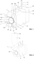
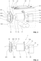
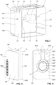
- Figures 1 to 7 are different embodiments of devices shown, with the Figures 1 to 4 to a first embodiment not according to the invention Figures 5 and 6 to a second embodiment not according to the invention and the figure 7 relate to a third embodiment of the invention.
- the Figures 8 and 9 show a fluid collection container 5 ', which in the figure 7 device shown can be connected.
- the in the Figures 1 to 7 The devices shown are particularly suitable for the combined negative pressure and instillation/irrigation treatment of wounds on the human or animal body. Accordingly, the following explanations each relate to the use of the devices in the combined negative pressure and instillation/irrigation treatment. In principle, however, it would also be possible to use these devices, with a correspondingly adapted design, for catheter flushing, eye surgery, liposuction or another medical application.
- the device of the first embodiment of the Figures 1 to 4 a pump assembly housing 1 with a fluid collection container 5 that can be connected to it.
- the pump assembly housing 1 has an overall essentially cuboid shape.
- an upper wall 14 a front wall 10 and a side wall 12 of the pump assembly housing 1 can be seen in each case.
- the side wall 12 In its corner region, where it is connected to the front wall 10, the side wall 12 has an indentation 120 which extends along the entire height of the side wall 12.
- the fluid collection container 5 also has an overall essentially cuboid shape.
- an upper wall 54 and a front wall 50 can be seen in each case. If the fluid collection container 5 as intended on Pump assembly housing 1 is connected, as in the Figures 1 and 2 is shown, it forms together with this an overall substantially cuboid shape with rounded outer edges and corners.
- the outer walls of the pump unit housing 1 and the fluid collection container 5 are each arranged in alignment with one another.
- the secretion line S is used to connect the fluid collection container 5 to a cavity or wound of a patient from which body fluids are to be aspirated, with the aspirated body fluids being collected in the fluid collection container 5 .
- the auxiliary line H it is possible to flush the secretion line S if necessary and/or to measure the pressure or the flow rate in the secretion line S.
- the auxiliary line H preferably opens into the secretion line S in the vicinity of the cavity or wound.
- the end of the secretion line S that is remote from the patient opens into the interior of the fluid collection container 5.
- the fluid collection container 5 In its side wall facing the pump assembly housing 1, the fluid collection container 5 has a vacuum connection, which cannot be seen in the figures and which connects a vacuum pump arranged in the pump assembly housing 1 to the interior of the fluid collection container 5. so that a vacuum can be generated inside the fluid collection container 5 by means of the vacuum pump.
- the auxiliary line H leads directly into the pump assembly housing 1 via the fluid collection container 5 and an auxiliary connection which is arranged in the same side wall as the vacuum connection and cannot be seen in the figures either.
- the side wall 12 of the pump unit housing 1 has a centrally arranged depression 121 .
- the depression 121 has the shape of a semicircular surface and is designed to be open toward the indentation 120 .
- the depression 121 has the same depth as the indentation 120 .
- the side wall 12 also forms a first guide channel 122 and a second guide channel 123 in the form of indentations arranged in a straight line and parallel to one another.
- the two guide channels 123 each open tangentially into the semicircular depression 121 at the top and bottom point respectively.
- An attachment pin 16 can be fitted with an attachment part 4 which has approximately the same dimensions as the indentation 120 .
- the mounting part 4 has a recess 40 designed to complement it.
- the push-on pin 16 can in particular be designed to snap into the recess 40 . Further and/or differently designed attachment structures for attaching the push-on part 4 to the pump assembly housing 1 are of course conceivable.
- the plug-on part 4 has a recess 41 which is open laterally towards the depression 121 and has the shape of a semicircular surface. Together with the depression 121, the recess 41 forms a circular depression when the push-on part 4 is attached to the pump unit housing 1 as intended.
- a pump head 30 of a peristaltic pump 3 is arranged within this circular depression.
- a plurality of pressure rollers 303 are freely rotatably attached to the periphery of the circular pump head 3 at regular intervals from one another along the circumferential direction.
- the semicircular space between the pump head 3 and the push-on part 4 forms a tube bed 42.
- the upper end of this tube bed 42 opens into the first guide channel 122 and the lower end into the second guide channel 123.
- the pump head 3 rotates about its longitudinal central axis, so that the pressure rollers 303 roll on a hose placed in the hose bed 42 .
- This tube forms an instillation line I and is, as in the figure 1 is shown, in the first and the second guide channel 122, 123 and the tube bed 42 is inserted.
- the instillation line I is deflected by 180°.
- the pressure rollers 303 press the tube against the plug-on part 4 so that a fluid substance contained in the instillation line I is pressed through the tube due to the mechanical deformation and transported to the wound area.
- the peristaltic pump 3 is thus in particular by the pump head 30, the hose bed 42 and the corresponding inserted therein Section of the instillation line I formed.
- a fluid substance is fed through the instillation line I to the cavity or wound of the patient.
- the substance can be, for example, a physiological or non-physiological saline solution, a drug or a mixture thereof.
- the instillation substance can be used to irrigate a wound or cavity. However, it can also be used to introduce medication or to numb the wound area locally.
- the instillation line I can in particular, as in the figure 2 shown, be connected to a liquid container 6 in which an instillation liquid is stored.
- the liquid container 6, which is embodied here as a bag, has a hanger 60 in order to hang it, for example, on an infusion stand with respect to the direction of gravity above the peristaltic pump 3. This ensures that there is always instillation liquid in the area of the peristaltic pump.
- a display and control panel 20 is arranged in the area of the upper wall 14 of the pump assembly housing 1 .
- the device can be operated with the aid of the display and control panel 20, and in particular the functions of the peristaltic pump 3 and the vacuum pump housed in the pump unit housing 1 can be set.
- the display and control panel 20 can be used to display information about the status of the device, such as in particular the current pump performance and cycles, etc.
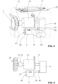
- FIGS Figures 3 and 4 The inner workings of the pump assembly housing 1 is shown schematically in FIGS Figures 3 and 4 shown.
- a drive train 7 with a drive in the form of a motor 70 is accommodated in particular in the interior of the pump assembly housing 1 .
- the motor 70 which is preferably a brushless DC motor, is used to drive the peristaltic pump 3 and the vacuum pump, which is designed as a diaphragm pump 8 here.
- the stator of the motor 70 is fastened to the pump assembly housing 1 in a rotationally fixed manner by means of a fastening plate 700 .
- the motor 70 has a rotor which is connected to a motor shaft 71 in a rotationally fixed manner.
- An axis of rotation of the drive train 7 is defined on the basis of the direction of rotation of the rotor of the motor 70 .
- the motor shaft 71 the longitudinal center axis of which coincides with the axis of rotation, projects out of the motor 70 with its two end regions on both sides.
- the first end region of the motor shaft 71 is connected to a first drive shaft 74 by means of a first freewheel 72
- the second end region of the motor shaft is connected to a second drive shaft 75 by means of a second freewheel 73 .
- the freewheels 72 and 73 represent clutches which only act in one direction of rotation, ie the rotational movement of the motor shaft 71 is only transmitted to the first or second drive shaft 74, 75 when the motor shaft 71 rotates in a specific direction. However, if the rotational speed of the drive shaft 74 or 75 is already greater than that of the motor shaft 71, no torque transmission takes place in the corresponding freewheel 72 or 73.
- the freewheels 72 and 73 can therefore also be referred to as overrunning clutches.
- the first drive shaft 74 and the second drive shaft 75 extend with their respective longitudinal center axes along the axis of rotation of the drive train 7.
- the directions of rotation in which torque is transmitted from the motor shaft to the first or second drive shaft 74, 75 are for the two freewheels 72 and 73 oriented in reverse directions.
- torque is therefore only transmitted to the first drive shaft 74, while the second drive shaft 75 is stationary. In this case, therefore, only the membrane pump 8 is driven, but not the peristaltic pump 3 .
- the direction of rotation of the motor 70 and thus the motor shaft 71 is reversed, only the peristaltic pump 3 but not the diaphragm pump 8 is driven.
- the drive train 7 is thus formed by the motor 70 , the motor shaft 71 , the two freewheels 72 and 73 and by the first drive shaft 74 and the second drive shaft 75 . Due to the two freewheels 72 and 73 oriented in opposite directions, it is ensured in this embodiment that only one of the two pumps 3 and 8 is in operation in any case. Depending on the direction of rotation of the motor 70, either the peristaltic pump 3 or the diaphragm pump 8 is driven.
- the membrane pump 8 serves to generate a vacuum in the fluid collection container 5 in order to suck in bodily fluids via the secretion line S and collect them in the fluid collection container.
- the diaphragm pump 8 has a vacuum connection 81 which can be connected to the vacuum connection of the fluid collection container 5 on the container side via a line not shown in the figures.
- the membrane pump 8 has an outlet 82 in order to expel the sucked-in air through it.
- the outlet 82 is connected to a line, not shown in the figures, which opens into the environment, i.e. to the outside.
- the diaphragm pump 8 is driven via the first drive shaft 74.
- the peristaltic pump 3 has a plurality of pressure rollers 303 .
- These pressure rollers 303 are mounted on a pump head 30 such that they can rotate freely about their respective axes and are arranged between two circular plates 301 and 302 extending parallel to one another.
- the axes of the pressure rollers 303 connect the two plates 301 and 302 to one another.
- the pump head 30 can be made to rotate about the axis of rotation of the drive train 7 via the second drive shaft 75 .
- An electronics unit 2 is also housed inside the pump assembly housing 1 .
- the electronics unit 2 has a printed circuit board (PCB) 22 on which electronic components 21, such as in particular a control unit, a motor output stage, pressure measurement sensors, a memory chip, etc., are arranged.
- a display and control elements, possibly a touch screen, are also arranged on the PCB 22 in order to form the display and control panel 20 .
- the electronics unit 2 serves in particular to set and regulate the direction of rotation and the rotational speed of the motor 70, depending on the inputs made by the user on the display and control panel 20.
- an energy store in the form of an accumulator 77 is also accommodated inside the pump assembly housing 1 .
- a pneumatic valve 9 is connected to the vacuum connection 81 of the membrane pump 8 via a connecting line 93.
- the pneumatic valve 9 has a vacuum connection 91 which is connected to the container-side vacuum connection of the fluid collection container 5 via a line not shown in the figures.
- the pneumatic valve has an inlet 92, which opens out into the environment via a further line, also not shown.
- the entire suction capacity generated by the diaphragm pump 8 or only part of it is present at the vacuum connection 91 .
- the pneumatic valve 9 can even be adjusted in such a way that the connecting line 93 is connected directly to the inlet 92 so that atmospheric pressure prevails in the fluid collection container 5 and thus in the secretion line S despite the operation of the membrane pump 8 . With such a valve position, instillation liquid can be fed in through the instillation line I without suction through the secretion line S taking place at the same time.
- the position of the pneumatic valve 9 can preferably be controlled by the electronics unit 2 as a function of the inputs made by the user on the display and control panel 20 .
- a third embodiment of the invention is in the Figures 7 to 9 shown.
- the device of this embodiment has a in the figure 7 shown pump assembly housing 1 'on which a in the Figures 8 and 9 shown fluid collection container 5 'can be connected.
- the pump assembly housing 1 ' has a total of substantially cuboid shape with a in the figure 7 not shown front wall, a rear wall 11 ', a first side wall 12' and a second side wall 13 'and a top wall 14' and a bottom wall 15 '.
- the front wall and the rear wall 11' each have a wall edge which protrudes from the first side wall 12' arranged therebetween.
- the fluid collection container 5' is held between these wall edges and can therefore be fastened to the pump assembly housing 1' in a simple but nevertheless safe and protected manner.
- receiving hooks 190' are provided on the pump assembly housing 1', into which correspondingly designed and arranged pins 554' of the fluid collection container 5' can engage.
- the fluid collection container 5' is secured on the pump unit housing 1' by means of a retaining lug 191' which is attached to a spring-loaded element and is designed to snap into a notch 553' formed on the fluid collection container 5'.
- the spring-loaded element on which the retaining lug 191' is attached can be pressed downwards against the spring force.
- the pump assembly housing 1' has a housing-side vacuum connection 17' which, when the fluid collection container 5' is attached to the pump assembly housing 1', is coupled to a corresponding container-side vacuum connection 551' provided on the fluid collection container 5', so that via the connections 17' and 551' in Inside the fluid collection container 5 'a vacuum can be generated.
- an adapter receptacle 18' which is used to receive a hose adapter (not shown in the figures).
- the hose adapter connects a secretion line (not shown in the figures) to the interior of the fluid collection container 5' via a secretion connection 552' on the container side provided on the fluid collection container 5'.
- a drive train 7' with a motor 70' and a motor shaft 71' connected to the motor 70' is housed inside the pump assembly housing 1'.
- the motor 70' can in particular be a brushless DC motor.
- the motor shaft 71 ' drives with a first end directly in the figure 7 Diaphragm pump not shown for representational reasons. With a second end portion, which in the figure 7 is not visible, the motor shaft 71' is connected to a freewheel 72', which connects the motor shaft 71' to a drive shaft 75'.
- the drive shaft 75' which extends along the axis of rotation of the motor shaft 71', protrudes through the first side wall 12'.
- a coupling element 76' is attached in a rotationally fixed manner to the end of the drive shaft 75'.
- the coupling element 76' has the form of a toothed wheel. In the present case it is a gear wheel with four teeth.
- a pump head 30' of a peristaltic pump 3' integrated in the fluid collection container 5' can be driven via the coupling element 76' when the fluid collection container 5' is attached to the pump assembly housing 1' as intended.
- the pump head 30' is not integrated in a fluid collection container but on any other part, such as an intermediate part, which can be coupled between the pump assembly housing 1' and a fluid collection container.
- the pump head 30' could in particular also represent part of a container in which the instillation substance is received.
- the container could have an identification feature and the device an identification unit to identify what type of substance is contained in the container.
- the device could then be designed to use one of several possible types depending on the type of substance identified To select operating modes for driving the first pump and the second pump or the coupling element or to limit the selection of the operating modes for the user depending on the substance.
- the identification feature can be read out electronically, for example by means of RFID. Such an identification and subsequent preselection of operating modes is of course also conceivable if the pump head is not integrated in the container with the substance to be identified.
- the fluid collection container 5' has a front wall 50', a rear wall which is not visible in the figures, two side walls 52' and 53' and an upper wall 54 and a lower wall which is also not visible. These walls are formed by a base part 55' made of an opaque material and a transparent part 56'. A filling level scale 560' is provided on that side wall 52' which is formed exclusively by the transparent part 56'.
- That side wall 53' which is formed exclusively by the base part 55' has a centrally arranged, annular depression 555'. Within the annular depression 555', the side wall 53' forms a concentrically arranged bearing journal 556' which has an upper, upwardly open recess 557'.
- a ring gear 57' is accommodated in the annular recess 555' and is freely rotatably arranged around the bearing journal 556'.
- pressure rollers (not visible in the figures) are freely rotatably mounted at regular intervals along the circumferential direction.
- the pressure rollers are used to roll onto a hose placed in the annular recess 555' on the radial outside of the ring gear 57'.
- the tube can form an instillation line 1 in particular. As the pressure rollers roll on the hose, it is compressed and the fluid contained in it is transported.
- a circumferential toothing 570' is formed on the ring gear 57' on its radial inner side.
- the ring gear 57' thus forms a peristaltic pump 3' together with the annular recess 555' and the instillation line I inserted therein, with the ring gear 57' forming the pump head 30'.
- corresponding guide channels for receiving the instillation line I are formed within the first side wall 12', which run straight and parallel to one another from the annular depression 555' upwards to the upper wall 54'.
- the fluid collection container 5' Essentially all parts of the fluid collection container 5', including the ring gear 57' and the pressure rollers attached thereto, are advantageously produced using the injection molding process. Since the fluid collection container 5' is usually a disposable part, which is often replaced and disposed of after a single use, the demands on the pump head 30 integrated therein are relatively low. The manufacturing costs for the entire device can thus be significantly reduced compared to a device in which the pump head is arranged in or on the pump assembly housing and must therefore be designed for a much longer service life.
- the drive train 7 or 7 ′ can also have one or more gears in order to change the rotational speed of the pump head 30 and/or the pumping frequency of the membrane pump 8 compared to that of the motor 70 .
- the peristaltic pump 3, 3' and the membrane pump 8 can be operated with different or the same pump frequencies, although they have a common drive in the form of the motor 70 or 70'.
- the gear or gears can, but do not have to, be combined with the freewheels 72, 72' and/or 73. They can thus be provided in addition to or as an alternative to the freewheels 72, 72' and 73.
- the invention described here is not limited to the embodiments mentioned and a large number of modifications are possible.
- the first and second pumps do not necessarily have to be in the form of a Diaphragm pump and a peristaltic pump are present, but depending on the application, any type of pump can be used for both pumps.
- the embodiments mentioned relate preferably to devices which are each designed to be portable, so that they can be carried comfortably by the user alone and without excessive effort. In principle, the devices described can be dimensioned as desired. A large number of other modifications are conceivable.
Landscapes
- Health & Medical Sciences (AREA)
- Engineering & Computer Science (AREA)
- Heart & Thoracic Surgery (AREA)
- Life Sciences & Earth Sciences (AREA)
- Veterinary Medicine (AREA)
- Public Health (AREA)
- General Health & Medical Sciences (AREA)
- Animal Behavior & Ethology (AREA)
- Biomedical Technology (AREA)
- Vascular Medicine (AREA)
- Anesthesiology (AREA)
- Hematology (AREA)
- General Engineering & Computer Science (AREA)
- Mechanical Engineering (AREA)
- Pulmonology (AREA)
- Ophthalmology & Optometry (AREA)
- Surgery (AREA)
- Nuclear Medicine, Radiotherapy & Molecular Imaging (AREA)
- Reciprocating Pumps (AREA)
- External Artificial Organs (AREA)
- Infusion, Injection, And Reservoir Apparatuses (AREA)
Claims (14)
- Dispositif d'aspiration de fluides corporels et d'alimentation d'une substance dans un corps humain ou animal, comprenantune première pompe (8) pour aspirer les fluides corporels ;un élément d'accouplement (7 6') pour accoupler de manière amovible une seconde pompe (3') afin d'acheminer la substance vers le corps au moyen de la seconde pompe (3, 3') ; etun entraînement (70, 70') pour entraîner la première pompe (8) ;caractérisé en ce quele même entraînement (70, 70') qui sert à entraîner la première pompe (8) sert également à entraîner la deuxième pompe (3, 3').
- Dispositif selon la revendication 1, la première pompe étant une pompe à vide, en particulier une pompe à membrane (8).
- Dispositif selon la revendication 2, le dispositif présentant en outre une vanne, en particulier une vanne pneumatique (9), au moyen de laquelle la pompe à vide (8) peut être reliée à l'environnement afin d'aspirer au moins partiellement de l'air de l'environnement au lieu de fluides corporels.
- Dispositif selon l'une quelconque des revendications précédentes, ledit dispositif étant destiné au traitement combiné par pression négative et instillation de plaies sur le corps humain ou animal.
- Dispositif selon l'une des revendications précédentes, le dispositif servant à l'aspiration et à l'irrigation combinées en liposuccion ou à l'aspiration et à l'irrigation combinées en chirurgie oculaire.
- Dispositif selon l'une des revendications précédentes, présentant un élément d'accouplement (76') pour l'accouplement d'une deuxième pompe (3') ainsi qu'un récipient de collecte de fluide (5') pour la collecte des fluides corporels aspirés, le récipient de collecte de fluide (5') présentant la deuxième pompe (3') et pouvant être accouplé avec celle-ci à l'élément d'accouplement (76').
- Dispositif selon l'une des revendications précédentes, comprenant en outre au moins une première roue libre (72, 73) au moyen de laquelle la première pompe (8) ou la deuxième pompe (3, 3') ou l'élément d'accouplement (76') est accouplé·e à l'entraînement (70, 70').
- Dispositif selon la revendication 7, la première pompe (8) étant accouplée à l'entraînement (70, 70') au moyen de la première roue libre (72), et dans lequel il existe en outre une deuxième roue libre (73), qui présente un sens de roue libre opposé à celui de la première roue libre (72), et au moyen de laquelle la deuxième pompe (3, 3') ou l'élément d'accouplement (76') est accouplé·e à l'entraînement (70, 70').
- Dispositif selon l'une quelconque des revendications précédentes, l'entraînement étant un moteur à courant continu sans balai (70, 70').
- Dispositif selon l'une des revendications précédentes, présentant un boîtier d'ensemble de pompes (1, 1') avec un espace intérieur dans lequel sont logés au moins la première pompe (8) et l'entraînement (70, 70').
- Dispositif selon la revendication 10, la deuxième pompe (3) ou l'élément d'accouplement (76') étant disposé·e sur un côté extérieur du boîtier d'ensemble de pompes (1, 1').
- Dispositif selon l'une des revendications précédentes, comprenant une unité motopropulseur (7, 7') dans laquelle l'entraînement (70, 70') est disposé entre la première pompe (8) et la deuxième pompe (3, 3') par l'intermédiaire de l'élément d'accouplement (76').
- Dispositif selon l'une des revendications précédentes, le dispositif étant conçu de telle sorte que le débit de pompage de la première pompe (8), d'une part, et le débit de pompage de la deuxième pompe (3, 3') ou la puissance induite par l'élément d'accouplement (76'), d'autre part, sont réglables dans une large mesure indépendamment les uns des autres.
- Dispositif selon l'une quelconque des revendications précédentes, le dispositif comprenant une unité d'identification pour identifier le type de substance à fournir qui est contenue dans un récipient qui comprend une unité d'identification et qui peut être attachée au dispositif, et le dispositif étant adapté pour sélectionner, en fonction du type de substance identifié, l'un de plusieurs modes de fonctionnement possibles pour entraîner la première pompe (8) et la deuxième pompe (3, 3') par l'intermédiaire de l'élément d'accouplement (76').
Applications Claiming Priority (3)
| Application Number | Priority Date | Filing Date | Title |
|---|---|---|---|
| EP16189671 | 2016-09-20 | ||
| EP17769056.7A EP3515519B1 (fr) | 2016-09-20 | 2017-09-18 | Dispositif d'aspiration de fluides corporels et d'acheminement d'une substance |
| PCT/EP2017/073466 WO2018054834A1 (fr) | 2016-09-20 | 2017-09-18 | Dispositif pour aspirer des fluides organiques et pour amener une substance |
Related Parent Applications (2)
| Application Number | Title | Priority Date | Filing Date |
|---|---|---|---|
| EP17769056.7A Division-Into EP3515519B1 (fr) | 2016-09-20 | 2017-09-18 | Dispositif d'aspiration de fluides corporels et d'acheminement d'une substance |
| EP17769056.7A Division EP3515519B1 (fr) | 2016-09-20 | 2017-09-18 | Dispositif d'aspiration de fluides corporels et d'acheminement d'une substance |
Publications (2)
| Publication Number | Publication Date |
|---|---|
| EP3603689A1 EP3603689A1 (fr) | 2020-02-05 |
| EP3603689B1 true EP3603689B1 (fr) | 2023-07-19 |
Family
ID=56958849
Family Applications (2)
| Application Number | Title | Priority Date | Filing Date |
|---|---|---|---|
| EP17769056.7A Active EP3515519B1 (fr) | 2016-09-20 | 2017-09-18 | Dispositif d'aspiration de fluides corporels et d'acheminement d'une substance |
| EP19199463.1A Active EP3603689B1 (fr) | 2016-09-20 | 2017-09-18 | Dispositif d'aspiration de fluides corporels et d'acheminement d'une substance |
Family Applications Before (1)
| Application Number | Title | Priority Date | Filing Date |
|---|---|---|---|
| EP17769056.7A Active EP3515519B1 (fr) | 2016-09-20 | 2017-09-18 | Dispositif d'aspiration de fluides corporels et d'acheminement d'une substance |
Country Status (5)
| Country | Link |
|---|---|
| US (1) | US11644026B2 (fr) |
| EP (2) | EP3515519B1 (fr) |
| CN (1) | CN109789251B (fr) |
| CA (1) | CA3035135A1 (fr) |
| WO (1) | WO2018054834A1 (fr) |
Families Citing this family (12)
| Publication number | Priority date | Publication date | Assignee | Title |
|---|---|---|---|---|
| US11090417B2 (en) | 2016-09-20 | 2021-08-17 | Medela Holding Ag | Suctioning and supply device with drive unit and connecting part |
| CN209679181U (zh) * | 2019-01-30 | 2019-11-26 | 深圳中科生物医疗电子有限公司 | 一种输注泵 |
| CN110552858B (zh) * | 2019-10-12 | 2025-02-11 | 卡川尔流体科技(上海)有限公司 | 一种多功能泵体组合结构 |
| WO2021094352A1 (fr) * | 2019-11-12 | 2021-05-20 | Medela Holding Ag | Dispositif d'extraction de fluide corporel par aspiration |
| US20230064788A1 (en) * | 2020-02-21 | 2023-03-02 | I Peace, Inc. | Solution transfer device |
| EP3878486A1 (fr) | 2020-03-13 | 2021-09-15 | Medela Holding AG | Dispositif de traitement sous pression et d'instillation de plaies |
| CN112089897B (zh) * | 2020-07-30 | 2023-09-15 | 京美德(深圳)医疗科技有限公司 | 一种介入式给药引流治疗装置 |
| EP4213779A4 (fr) * | 2020-09-20 | 2024-09-11 | Microsurgical Technology, Inc. | Commande fluidique pour dispositifs microchirurgicaux |
| US11957365B2 (en) | 2020-11-20 | 2024-04-16 | Covidien Lp | Aspiration pulsator |
| US20230296468A1 (en) * | 2022-03-17 | 2023-09-21 | Kabir Bhandari | Dual mode fuel tank leakage detector |
| EP4309698A1 (fr) | 2022-07-22 | 2024-01-24 | Medela Holding AG | Pompe péristaltique à engrenage planétaire |
| EP4488520B1 (fr) * | 2023-07-07 | 2026-02-04 | Fas Medic S.A. | Appareil de distribution de fluide |
Family Cites Families (46)
| Publication number | Priority date | Publication date | Assignee | Title |
|---|---|---|---|---|
| US4634024A (en) | 1984-01-16 | 1987-01-06 | Technical Innovations, Inc. | Automatic resin dispensing apparatus |
| US5125891A (en) * | 1987-04-27 | 1992-06-30 | Site Microsurgical Systems, Inc. | Disposable vacuum/peristaltic pump cassette system |
| US4798580A (en) | 1987-04-27 | 1989-01-17 | Site Microsurgical Systems, Inc. | Disposable peristaltic pump cassette system |
| FR2624377A1 (fr) | 1987-12-09 | 1989-06-16 | Mambrini Jean | Instillateur a microdebit |
| FR2624378A1 (fr) | 1987-12-09 | 1989-06-16 | Mambrini Jean | Instillateur a microdebit |
| FR2624376A1 (fr) | 1987-12-09 | 1989-06-16 | Mambrini Jean | Instillateur a microdebit jetable |
| US5388972A (en) * | 1994-03-09 | 1995-02-14 | Medical Laboratory Automation, Inc. | Peristaltic pump with removable tubing of precise length |
| US5611335A (en) * | 1995-06-06 | 1997-03-18 | Makhoul; Imad R. | High-frequency fan ventilator |
| US5772255A (en) * | 1995-09-21 | 1998-06-30 | Abbott Laboratories | Tubing connector |
| EP0918551B1 (fr) | 1996-08-15 | 2004-11-03 | Deka Products Limited Partnership | Pompe et systeme d'irrigation medicale |
| JP4021049B2 (ja) * | 1998-05-13 | 2007-12-12 | オリンパス株式会社 | 焼灼止血装置 |
| DE19821794A1 (de) * | 1998-05-15 | 1999-11-18 | Continental Teves Ag & Co Ohg | Motorpumpenaggregat |
| JP3205300B2 (ja) * | 1998-06-01 | 2001-09-04 | プラス医科工業株式会社 | 医療用吸引器 |
| US6290690B1 (en) * | 1999-06-21 | 2001-09-18 | Alcon Manufacturing, Ltd. | Simultaneous injection and aspiration of viscous fluids in a surgical system |
| EP2275157A3 (fr) * | 2002-05-16 | 2012-02-15 | Scott Laboratories, Inc. | Kits de fournitures médicales pour la sédation et l'analgésie |
| US7625362B2 (en) | 2003-09-16 | 2009-12-01 | Boehringer Technologies, L.P. | Apparatus and method for suction-assisted wound healing |
| WO2004071554A2 (fr) | 2003-02-11 | 2004-08-26 | Dilip Tapadiya | Equipement d'irrigation de plaie |
| US7238010B2 (en) | 2003-04-14 | 2007-07-03 | Stryker Corporation | Surgical irrigation pump and tool system |
| US7753880B2 (en) * | 2004-09-28 | 2010-07-13 | Stryker Corporation | Method of operating a surgical irrigation pump capable of performing a priming operation |
| JP5154228B2 (ja) | 2004-11-05 | 2013-02-27 | コンバテック・テクノロジーズ・インコーポレイテッド | 真空創傷包帯 |
| US7850431B2 (en) * | 2005-12-02 | 2010-12-14 | Entegris, Inc. | System and method for control of fluid pressure |
| US20070258838A1 (en) * | 2006-05-03 | 2007-11-08 | Sherwood Services Ag | Peristaltic cooling pump system |
| US20080132763A1 (en) * | 2006-12-04 | 2008-06-05 | Isaacson Keith B | Apparatus And Method For An Endoscope Pump |
| US20080147008A1 (en) * | 2006-12-15 | 2008-06-19 | Tyco Healthcare Group Lp | Optical detection of medical pump rotor position |
| US20080154184A1 (en) | 2006-12-20 | 2008-06-26 | Blight David D | Arthroscopic irrigation/aspiration pump system with declogging feature |
| US7510542B2 (en) | 2006-12-20 | 2009-03-31 | Linvatec Corporation | Dual pump irrigation/aspiration system and method for determining joint pressure |
| US20080154182A1 (en) | 2006-12-20 | 2008-06-26 | Robert Martin | Dual diameter arthroscopic irrigation/aspiration peristaltic pump system |
| US8591453B2 (en) | 2006-12-20 | 2013-11-26 | Linvatec Corporation | Dual pump arthroscopic irrigation/aspiration system with outflow control |
| AU2013205327B2 (en) * | 2007-12-27 | 2015-11-26 | Devicor Medical Products, Inc. | Clutch and valving system for tetherless biopsy device |
| US20100036333A1 (en) * | 2008-08-06 | 2010-02-11 | Schenk Iii Albert A | Fluid level sensor for a container of a negative pressure wound treatment system |
| DE102009038131A1 (de) | 2009-08-12 | 2011-02-17 | ATMOS Medizin Technik GmbH & Co. KG | Am Körper eines Benutzers tragbare Vorrichtung zur Bereitstellung von Unterdruck für medizinische Anwendungen |
| FR2960423B1 (fr) * | 2010-05-27 | 2013-03-08 | Laurent Michel Marie Charroin | Dispositif d'administration de liquide charge ou non de substances a visee naso-sinusienne |
| US10076592B2 (en) * | 2011-06-23 | 2018-09-18 | Medela Holding Ag | System for aspirating fluids from a body using negative pressure |
| EP2760406A4 (fr) * | 2011-09-30 | 2015-08-12 | Eksigent Technologies Llc | Procédés et système de traitement de plaie basé sur une pompe électrocinétique |
| PL2766064T3 (pl) * | 2011-12-08 | 2017-08-31 | Alcon Research, Ltd. | Selektywnie przemieszczalne elementy zaworowe dla obwodów zasysania i irygacji |
| EP2606918B1 (fr) * | 2011-12-21 | 2014-06-25 | MAPA GmbH | Tire-lait maternel électrique |
| GB201216928D0 (en) | 2012-09-21 | 2012-11-07 | I2R Medical Ltd | Portable medical device system |
| KR101854585B1 (ko) * | 2012-11-14 | 2018-06-20 | 코비디엔 엘피 | 연동 펌프 카세트 |
| EP2922587B1 (fr) | 2012-11-26 | 2019-09-04 | KCI Licensing, Inc. | Pompe et système de stockage de solution combinés pour utilisation avec un système de traitement à pression réduite |
| JP6069810B2 (ja) * | 2013-07-30 | 2017-02-01 | コーニンクレッカ フィリップス エヌ ヴェKoninklijke Philips N.V. | システムから排出するための機器及び方法 |
| DE102013226708A1 (de) | 2013-12-19 | 2015-06-25 | Paul Hartmann Ag | System zur kombinierten Unterdruck- und Instillationsbehandlung von Wunden |
| WO2016010792A1 (fr) | 2014-07-18 | 2016-01-21 | Kci Licensing, Inc. | Cartouche d'instillation et système de thérapie pour une thérapie par pression négative et une thérapie d'instillation |
| US20170304527A1 (en) | 2014-10-03 | 2017-10-26 | Mayo Foundation For Medical Education And Research | Wound irrigation system |
| CA2965503A1 (fr) | 2014-10-24 | 2016-04-28 | Kci Licensing, Inc. | Therapie a pression negative avec instillation a actionnement pneumatique |
| CN104771801A (zh) | 2015-01-26 | 2015-07-15 | 唐佩福 | 一种创面负压吸引冲洗仪器 |
| DE202015006341U1 (de) * | 2015-09-08 | 2015-11-06 | Michael Eichler | Pumpenkassette |
-
2017
- 2017-09-18 CN CN201780058050.7A patent/CN109789251B/zh active Active
- 2017-09-18 CA CA3035135A patent/CA3035135A1/fr active Pending
- 2017-09-18 WO PCT/EP2017/073466 patent/WO2018054834A1/fr not_active Ceased
- 2017-09-18 US US16/333,877 patent/US11644026B2/en active Active
- 2017-09-18 EP EP17769056.7A patent/EP3515519B1/fr active Active
- 2017-09-18 EP EP19199463.1A patent/EP3603689B1/fr active Active
Also Published As
| Publication number | Publication date |
|---|---|
| CN109789251B (zh) | 2021-12-28 |
| EP3515519A1 (fr) | 2019-07-31 |
| US20190201598A1 (en) | 2019-07-04 |
| US11644026B2 (en) | 2023-05-09 |
| CN109789251A (zh) | 2019-05-21 |
| WO2018054834A1 (fr) | 2018-03-29 |
| EP3515519B1 (fr) | 2023-11-01 |
| EP3603689A1 (fr) | 2020-02-05 |
| CA3035135A1 (fr) | 2018-03-29 |
Similar Documents
| Publication | Publication Date | Title |
|---|---|---|
| EP3515519B1 (fr) | Dispositif d'aspiration de fluides corporels et d'acheminement d'une substance | |
| EP3515518B1 (fr) | Dispositif d'aspiration et d'alimentation comprenant une unite d'entrainement et bloc de raccordement | |
| EP1633414B2 (fr) | Pompe de perfusion modulaire | |
| EP2533826B1 (fr) | Installation médicale, dispositif de traitement et procédés | |
| EP3142728B1 (fr) | Dispositif de dosage pour la perfusion d'un medicament liquide d'une cartouche comprenant une tige telescopique pour deplacer le piston | |
| EP2145637B1 (fr) | Unité de pompe d'aspiration | |
| EP2598182B1 (fr) | Système de pompe d'aspiration | |
| DE69616336T2 (de) | Peristaltikpumpe | |
| WO2011124388A1 (fr) | Dispositif d'aspiration pour aspirer un liquide corporel | |
| EP2723413B1 (fr) | Système destiné à aspirer des fluides hors d'un corps par un effet de dépression | |
| WO2011035448A1 (fr) | Téterelle pour pomper du lait maternel humain | |
| DE19725462A1 (de) | Medizinische Zahnradpumpe zum Saugen und Spülen | |
| EP3600470B1 (fr) | Dispositif comprenant une unité de pompe péristaltique pouvant être couplée | |
| EP4626501A1 (fr) | Système de lavage, en particulier système de lavage pulsé | |
| CN116367872A (zh) | 具有集成冲洗流体泵头的伤口流体收集罐 | |
| EP3878486A1 (fr) | Dispositif de traitement sous pression et d'instillation de plaies | |
| EP0173816A2 (fr) | Dispositif d'irrigation et d'aspiration pour l'endoscopie | |
| WO2024114847A1 (fr) | Système de lavage, en particulier système de lavage pulsé | |
| DE202005019583U1 (de) | Gerät zum Abpumpen von Muttermilch |
Legal Events
| Date | Code | Title | Description |
|---|---|---|---|
| PUAI | Public reference made under article 153(3) epc to a published international application that has entered the european phase |
Free format text: ORIGINAL CODE: 0009012 |
|
| STAA | Information on the status of an ep patent application or granted ep patent |
Free format text: STATUS: THE APPLICATION HAS BEEN PUBLISHED |
|
| AC | Divisional application: reference to earlier application |
Ref document number: 3515519 Country of ref document: EP Kind code of ref document: P |
|
| AK | Designated contracting states |
Kind code of ref document: A1 Designated state(s): AL AT BE BG CH CY CZ DE DK EE ES FI FR GB GR HR HU IE IS IT LI LT LU LV MC MK MT NL NO PL PT RO RS SE SI SK SM TR |
|
| AX | Request for extension of the european patent |
Extension state: BA ME |
|
| STAA | Information on the status of an ep patent application or granted ep patent |
Free format text: STATUS: REQUEST FOR EXAMINATION WAS MADE |
|
| 17P | Request for examination filed |
Effective date: 20200609 |
|
| RBV | Designated contracting states (corrected) |
Designated state(s): AL AT BE BG CH CY CZ DE DK EE ES FI FR GB GR HR HU IE IS IT LI LT LU LV MC MK MT NL NO PL PT RO RS SE SI SK SM TR |
|
| STAA | Information on the status of an ep patent application or granted ep patent |
Free format text: STATUS: EXAMINATION IS IN PROGRESS |
|
| 17Q | First examination report despatched |
Effective date: 20221124 |
|
| GRAP | Despatch of communication of intention to grant a patent |
Free format text: ORIGINAL CODE: EPIDOSNIGR1 |
|
| STAA | Information on the status of an ep patent application or granted ep patent |
Free format text: STATUS: GRANT OF PATENT IS INTENDED |
|
| INTG | Intention to grant announced |
Effective date: 20230214 |
|
| GRAS | Grant fee paid |
Free format text: ORIGINAL CODE: EPIDOSNIGR3 |
|
| GRAA | (expected) grant |
Free format text: ORIGINAL CODE: 0009210 |
|
| STAA | Information on the status of an ep patent application or granted ep patent |
Free format text: STATUS: THE PATENT HAS BEEN GRANTED |
|
| P01 | Opt-out of the competence of the unified patent court (upc) registered |
Effective date: 20230524 |
|
| AC | Divisional application: reference to earlier application |
Ref document number: 3515519 Country of ref document: EP Kind code of ref document: P |
|
| AK | Designated contracting states |
Kind code of ref document: B1 Designated state(s): AL AT BE BG CH CY CZ DE DK EE ES FI FR GB GR HR HU IE IS IT LI LT LU LV MC MK MT NL NO PL PT RO RS SE SI SK SM TR |
|
| REG | Reference to a national code |
Ref country code: GB Ref legal event code: FG4D Free format text: NOT ENGLISH |
|
| REG | Reference to a national code |
Ref country code: CH Ref legal event code: EP |
|
| REG | Reference to a national code |
Ref country code: DE Ref legal event code: R096 Ref document number: 502017015084 Country of ref document: DE |
|
| REG | Reference to a national code |
Ref country code: IE Ref legal event code: FG4D Free format text: LANGUAGE OF EP DOCUMENT: GERMAN |
|
| REG | Reference to a national code |
Ref country code: LT Ref legal event code: MG9D |
|
| REG | Reference to a national code |
Ref country code: NL Ref legal event code: MP Effective date: 20230719 |
|
| PG25 | Lapsed in a contracting state [announced via postgrant information from national office to epo] |
Ref country code: NL Free format text: LAPSE BECAUSE OF FAILURE TO SUBMIT A TRANSLATION OF THE DESCRIPTION OR TO PAY THE FEE WITHIN THE PRESCRIBED TIME-LIMIT Effective date: 20230719 |
|
| PG25 | Lapsed in a contracting state [announced via postgrant information from national office to epo] |
Ref country code: GR Free format text: LAPSE BECAUSE OF FAILURE TO SUBMIT A TRANSLATION OF THE DESCRIPTION OR TO PAY THE FEE WITHIN THE PRESCRIBED TIME-LIMIT Effective date: 20231020 |
|
| PG25 | Lapsed in a contracting state [announced via postgrant information from national office to epo] |
Ref country code: IS Free format text: LAPSE BECAUSE OF FAILURE TO SUBMIT A TRANSLATION OF THE DESCRIPTION OR TO PAY THE FEE WITHIN THE PRESCRIBED TIME-LIMIT Effective date: 20231119 |
|
| PG25 | Lapsed in a contracting state [announced via postgrant information from national office to epo] |
Ref country code: SE Free format text: LAPSE BECAUSE OF FAILURE TO SUBMIT A TRANSLATION OF THE DESCRIPTION OR TO PAY THE FEE WITHIN THE PRESCRIBED TIME-LIMIT Effective date: 20230719 Ref country code: RS Free format text: LAPSE BECAUSE OF FAILURE TO SUBMIT A TRANSLATION OF THE DESCRIPTION OR TO PAY THE FEE WITHIN THE PRESCRIBED TIME-LIMIT Effective date: 20230719 Ref country code: PT Free format text: LAPSE BECAUSE OF FAILURE TO SUBMIT A TRANSLATION OF THE DESCRIPTION OR TO PAY THE FEE WITHIN THE PRESCRIBED TIME-LIMIT Effective date: 20231120 Ref country code: NO Free format text: LAPSE BECAUSE OF FAILURE TO SUBMIT A TRANSLATION OF THE DESCRIPTION OR TO PAY THE FEE WITHIN THE PRESCRIBED TIME-LIMIT Effective date: 20231019 Ref country code: LV Free format text: LAPSE BECAUSE OF FAILURE TO SUBMIT A TRANSLATION OF THE DESCRIPTION OR TO PAY THE FEE WITHIN THE PRESCRIBED TIME-LIMIT Effective date: 20230719 Ref country code: LT Free format text: LAPSE BECAUSE OF FAILURE TO SUBMIT A TRANSLATION OF THE DESCRIPTION OR TO PAY THE FEE WITHIN THE PRESCRIBED TIME-LIMIT Effective date: 20230719 Ref country code: IS Free format text: LAPSE BECAUSE OF FAILURE TO SUBMIT A TRANSLATION OF THE DESCRIPTION OR TO PAY THE FEE WITHIN THE PRESCRIBED TIME-LIMIT Effective date: 20231119 Ref country code: HR Free format text: LAPSE BECAUSE OF FAILURE TO SUBMIT A TRANSLATION OF THE DESCRIPTION OR TO PAY THE FEE WITHIN THE PRESCRIBED TIME-LIMIT Effective date: 20230719 Ref country code: GR Free format text: LAPSE BECAUSE OF FAILURE TO SUBMIT A TRANSLATION OF THE DESCRIPTION OR TO PAY THE FEE WITHIN THE PRESCRIBED TIME-LIMIT Effective date: 20231020 Ref country code: FI Free format text: LAPSE BECAUSE OF FAILURE TO SUBMIT A TRANSLATION OF THE DESCRIPTION OR TO PAY THE FEE WITHIN THE PRESCRIBED TIME-LIMIT Effective date: 20230719 |
|
| PG25 | Lapsed in a contracting state [announced via postgrant information from national office to epo] |
Ref country code: PL Free format text: LAPSE BECAUSE OF FAILURE TO SUBMIT A TRANSLATION OF THE DESCRIPTION OR TO PAY THE FEE WITHIN THE PRESCRIBED TIME-LIMIT Effective date: 20230719 |
|
| REG | Reference to a national code |
Ref country code: DE Ref legal event code: R097 Ref document number: 502017015084 Country of ref document: DE |
|
| PG25 | Lapsed in a contracting state [announced via postgrant information from national office to epo] |
Ref country code: ES Free format text: LAPSE BECAUSE OF FAILURE TO SUBMIT A TRANSLATION OF THE DESCRIPTION OR TO PAY THE FEE WITHIN THE PRESCRIBED TIME-LIMIT Effective date: 20230719 |
|
| PG25 | Lapsed in a contracting state [announced via postgrant information from national office to epo] |
Ref country code: SM Free format text: LAPSE BECAUSE OF FAILURE TO SUBMIT A TRANSLATION OF THE DESCRIPTION OR TO PAY THE FEE WITHIN THE PRESCRIBED TIME-LIMIT Effective date: 20230719 Ref country code: RO Free format text: LAPSE BECAUSE OF FAILURE TO SUBMIT A TRANSLATION OF THE DESCRIPTION OR TO PAY THE FEE WITHIN THE PRESCRIBED TIME-LIMIT Effective date: 20230719 Ref country code: ES Free format text: LAPSE BECAUSE OF FAILURE TO SUBMIT A TRANSLATION OF THE DESCRIPTION OR TO PAY THE FEE WITHIN THE PRESCRIBED TIME-LIMIT Effective date: 20230719 Ref country code: EE Free format text: LAPSE BECAUSE OF FAILURE TO SUBMIT A TRANSLATION OF THE DESCRIPTION OR TO PAY THE FEE WITHIN THE PRESCRIBED TIME-LIMIT Effective date: 20230719 Ref country code: DK Free format text: LAPSE BECAUSE OF FAILURE TO SUBMIT A TRANSLATION OF THE DESCRIPTION OR TO PAY THE FEE WITHIN THE PRESCRIBED TIME-LIMIT Effective date: 20230719 Ref country code: CZ Free format text: LAPSE BECAUSE OF FAILURE TO SUBMIT A TRANSLATION OF THE DESCRIPTION OR TO PAY THE FEE WITHIN THE PRESCRIBED TIME-LIMIT Effective date: 20230719 Ref country code: SK Free format text: LAPSE BECAUSE OF FAILURE TO SUBMIT A TRANSLATION OF THE DESCRIPTION OR TO PAY THE FEE WITHIN THE PRESCRIBED TIME-LIMIT Effective date: 20230719 |
|
| REG | Reference to a national code |
Ref country code: CH Ref legal event code: PL |
|
| PG25 | Lapsed in a contracting state [announced via postgrant information from national office to epo] |
Ref country code: LU Free format text: LAPSE BECAUSE OF NON-PAYMENT OF DUE FEES Effective date: 20230918 |
|
| PLBE | No opposition filed within time limit |
Free format text: ORIGINAL CODE: 0009261 |
|
| STAA | Information on the status of an ep patent application or granted ep patent |
Free format text: STATUS: NO OPPOSITION FILED WITHIN TIME LIMIT |
|
| REG | Reference to a national code |
Ref country code: BE Ref legal event code: MM Effective date: 20230930 |
|
| PG25 | Lapsed in a contracting state [announced via postgrant information from national office to epo] |
Ref country code: LU Free format text: LAPSE BECAUSE OF NON-PAYMENT OF DUE FEES Effective date: 20230918 Ref country code: IT Free format text: LAPSE BECAUSE OF FAILURE TO SUBMIT A TRANSLATION OF THE DESCRIPTION OR TO PAY THE FEE WITHIN THE PRESCRIBED TIME-LIMIT Effective date: 20230719 Ref country code: MC Free format text: LAPSE BECAUSE OF FAILURE TO SUBMIT A TRANSLATION OF THE DESCRIPTION OR TO PAY THE FEE WITHIN THE PRESCRIBED TIME-LIMIT Effective date: 20230719 |
|
| 26N | No opposition filed |
Effective date: 20240422 |
|
| GBPC | Gb: european patent ceased through non-payment of renewal fee |
Effective date: 20231019 |
|
| REG | Reference to a national code |
Ref country code: IE Ref legal event code: MM4A |
|
| PG25 | Lapsed in a contracting state [announced via postgrant information from national office to epo] |
Ref country code: IE Free format text: LAPSE BECAUSE OF NON-PAYMENT OF DUE FEES Effective date: 20230918 |
|
| PG25 | Lapsed in a contracting state [announced via postgrant information from national office to epo] |
Ref country code: GB Free format text: LAPSE BECAUSE OF NON-PAYMENT OF DUE FEES Effective date: 20231019 |
|
| PG25 | Lapsed in a contracting state [announced via postgrant information from national office to epo] |
Ref country code: CH Free format text: LAPSE BECAUSE OF NON-PAYMENT OF DUE FEES Effective date: 20230930 |
|
| PG25 | Lapsed in a contracting state [announced via postgrant information from national office to epo] |
Ref country code: IE Free format text: LAPSE BECAUSE OF NON-PAYMENT OF DUE FEES Effective date: 20230918 Ref country code: GB Free format text: LAPSE BECAUSE OF NON-PAYMENT OF DUE FEES Effective date: 20231019 Ref country code: FR Free format text: LAPSE BECAUSE OF NON-PAYMENT OF DUE FEES Effective date: 20230919 Ref country code: CH Free format text: LAPSE BECAUSE OF NON-PAYMENT OF DUE FEES Effective date: 20230930 Ref country code: SI Free format text: LAPSE BECAUSE OF FAILURE TO SUBMIT A TRANSLATION OF THE DESCRIPTION OR TO PAY THE FEE WITHIN THE PRESCRIBED TIME-LIMIT Effective date: 20230719 |
|
| PG25 | Lapsed in a contracting state [announced via postgrant information from national office to epo] |
Ref country code: BE Free format text: LAPSE BECAUSE OF NON-PAYMENT OF DUE FEES Effective date: 20230930 |
|
| PG25 | Lapsed in a contracting state [announced via postgrant information from national office to epo] |
Ref country code: BG Free format text: LAPSE BECAUSE OF FAILURE TO SUBMIT A TRANSLATION OF THE DESCRIPTION OR TO PAY THE FEE WITHIN THE PRESCRIBED TIME-LIMIT Effective date: 20230719 |
|
| REG | Reference to a national code |
Ref country code: AT Ref legal event code: MM01 Ref document number: 1588825 Country of ref document: AT Kind code of ref document: T Effective date: 20230918 |
|
| PG25 | Lapsed in a contracting state [announced via postgrant information from national office to epo] |
Ref country code: BG Free format text: LAPSE BECAUSE OF FAILURE TO SUBMIT A TRANSLATION OF THE DESCRIPTION OR TO PAY THE FEE WITHIN THE PRESCRIBED TIME-LIMIT Effective date: 20230719 |
|
| PG25 | Lapsed in a contracting state [announced via postgrant information from national office to epo] |
Ref country code: AT Free format text: LAPSE BECAUSE OF NON-PAYMENT OF DUE FEES Effective date: 20230918 |
|
| PG25 | Lapsed in a contracting state [announced via postgrant information from national office to epo] |
Ref country code: AT Free format text: LAPSE BECAUSE OF NON-PAYMENT OF DUE FEES Effective date: 20230918 |
|
| PG25 | Lapsed in a contracting state [announced via postgrant information from national office to epo] |
Ref country code: CY Free format text: LAPSE BECAUSE OF FAILURE TO SUBMIT A TRANSLATION OF THE DESCRIPTION OR TO PAY THE FEE WITHIN THE PRESCRIBED TIME-LIMIT; INVALID AB INITIO Effective date: 20170918 |
|
| PG25 | Lapsed in a contracting state [announced via postgrant information from national office to epo] |
Ref country code: HU Free format text: LAPSE BECAUSE OF FAILURE TO SUBMIT A TRANSLATION OF THE DESCRIPTION OR TO PAY THE FEE WITHIN THE PRESCRIBED TIME-LIMIT; INVALID AB INITIO Effective date: 20170918 |
|
| PGFP | Annual fee paid to national office [announced via postgrant information from national office to epo] |
Ref country code: DE Payment date: 20250919 Year of fee payment: 9 |
|
| PG25 | Lapsed in a contracting state [announced via postgrant information from national office to epo] |
Ref country code: TR Free format text: LAPSE BECAUSE OF FAILURE TO SUBMIT A TRANSLATION OF THE DESCRIPTION OR TO PAY THE FEE WITHIN THE PRESCRIBED TIME-LIMIT Effective date: 20230719 |