EP3603707B1 - Ensemble d'aiguille de sécurité - Google Patents
Ensemble d'aiguille de sécurité Download PDFInfo
- Publication number
- EP3603707B1 EP3603707B1 EP19193274.8A EP19193274A EP3603707B1 EP 3603707 B1 EP3603707 B1 EP 3603707B1 EP 19193274 A EP19193274 A EP 19193274A EP 3603707 B1 EP3603707 B1 EP 3603707B1
- Authority
- EP
- European Patent Office
- Prior art keywords
- sheath
- cannula
- collar
- distal end
- needle assembly
- Prior art date
- Legal status (The legal status is an assumption and is not a legal conclusion. Google has not performed a legal analysis and makes no representation as to the accuracy of the status listed.)
- Active
Links
Images




Classifications
-
- A—HUMAN NECESSITIES
- A61—MEDICAL OR VETERINARY SCIENCE; HYGIENE
- A61M—DEVICES FOR INTRODUCING MEDIA INTO, OR ONTO, THE BODY; DEVICES FOR TRANSDUCING BODY MEDIA OR FOR TAKING MEDIA FROM THE BODY; DEVICES FOR PRODUCING OR ENDING SLEEP OR STUPOR
- A61M5/00—Devices for bringing media into the body in a subcutaneous, intra-vascular or intramuscular way; Accessories therefor, e.g. filling or cleaning devices, arm-rests
- A61M5/178—Syringes
- A61M5/31—Details
- A61M5/32—Needles; Details of needles pertaining to their connection with syringe or hub; Accessories for bringing the needle into, or holding the needle on, the body; Devices for protection of needles
- A61M5/3205—Apparatus for removing or disposing of used needles or syringes, e.g. containers; Means for protection against accidental injuries from used needles
- A61M5/321—Means for protection against accidental injuries by used needles
- A61M5/3216—Caps placed transversally onto the needle, e.g. pivotally attached to the needle base
- A61M5/3219—Semi-automatic repositioning of the cap, i.e. in which the repositioning of the cap to the needle covering position requires a deliberate action by the user to trigger the repositioning of the cap, e.g. manual release of spring-biased cap repositioning means
-
- A—HUMAN NECESSITIES
- A61—MEDICAL OR VETERINARY SCIENCE; HYGIENE
- A61M—DEVICES FOR INTRODUCING MEDIA INTO, OR ONTO, THE BODY; DEVICES FOR TRANSDUCING BODY MEDIA OR FOR TAKING MEDIA FROM THE BODY; DEVICES FOR PRODUCING OR ENDING SLEEP OR STUPOR
- A61M5/00—Devices for bringing media into the body in a subcutaneous, intra-vascular or intramuscular way; Accessories therefor, e.g. filling or cleaning devices, arm-rests
- A61M5/178—Syringes
- A61M5/31—Details
- A61M5/32—Needles; Details of needles pertaining to their connection with syringe or hub; Accessories for bringing the needle into, or holding the needle on, the body; Devices for protection of needles
- A61M5/3205—Apparatus for removing or disposing of used needles or syringes, e.g. containers; Means for protection against accidental injuries from used needles
- A61M5/321—Means for protection against accidental injuries by used needles
- A61M5/3216—Caps placed transversally onto the needle, e.g. pivotally attached to the needle base
-
- A—HUMAN NECESSITIES
- A61—MEDICAL OR VETERINARY SCIENCE; HYGIENE
- A61M—DEVICES FOR INTRODUCING MEDIA INTO, OR ONTO, THE BODY; DEVICES FOR TRANSDUCING BODY MEDIA OR FOR TAKING MEDIA FROM THE BODY; DEVICES FOR PRODUCING OR ENDING SLEEP OR STUPOR
- A61M5/00—Devices for bringing media into the body in a subcutaneous, intra-vascular or intramuscular way; Accessories therefor, e.g. filling or cleaning devices, arm-rests
- A61M5/178—Syringes
- A61M5/31—Details
- A61M5/32—Needles; Details of needles pertaining to their connection with syringe or hub; Accessories for bringing the needle into, or holding the needle on, the body; Devices for protection of needles
- A61M5/3205—Apparatus for removing or disposing of used needles or syringes, e.g. containers; Means for protection against accidental injuries from used needles
- A61M5/321—Means for protection against accidental injuries by used needles
- A61M5/3216—Caps placed transversally onto the needle, e.g. pivotally attached to the needle base
- A61M2005/3217—Means to impede repositioning of protection cap from needle covering to needle uncovering position, e.g. catch mechanisms
-
- A—HUMAN NECESSITIES
- A61—MEDICAL OR VETERINARY SCIENCE; HYGIENE
- A61M—DEVICES FOR INTRODUCING MEDIA INTO, OR ONTO, THE BODY; DEVICES FOR TRANSDUCING BODY MEDIA OR FOR TAKING MEDIA FROM THE BODY; DEVICES FOR PRODUCING OR ENDING SLEEP OR STUPOR
- A61M5/00—Devices for bringing media into the body in a subcutaneous, intra-vascular or intramuscular way; Accessories therefor, e.g. filling or cleaning devices, arm-rests
- A61M5/178—Syringes
- A61M5/31—Details
- A61M5/32—Needles; Details of needles pertaining to their connection with syringe or hub; Accessories for bringing the needle into, or holding the needle on, the body; Devices for protection of needles
- A61M5/3202—Devices for protection of the needle before use, e.g. caps
Definitions
- the present invention relates to a safety needle assembly according to the preamble of claim 1, the features of which are known from e.g. document US 2007/265566 A1 .
- a method for preventing such a sting accident from happening for example, including a means of covering a used needle with a cylindrical cap.
- a user may erroneously stick a needle into one of user's fingers holding the cap. Therefore, this method cannot be perfectly safe for preventing a sting accident.
- documents JP 2000-140109 A and JP 2005-525198 A disclose a technique for preventing a sting accident by using a needle assembly comprised of a sheath (or shield) for covering a needle.
- a user can utilize the needle assembly in the steps of: using a needle for a medical treatment; pivoting a sheath by finger(s) so as to cover the used needle with the sheath; and fixing the state that the used needle is covered by the sheath.
- Document US 2007/265566 A1 pertains to a fixed needle syringe, that has a syringe barrel with its distal portion modified to accept a needle protective housing.
- the distal portion is formed with a groove dimensioned to accept a collar that is attached to the housing.
- the inside surface of the collar is provided with a number of flanges that fit within the groove formed at the distal portion of the syringe barrel of the fixed needle syringe.
- Protrusions are provided at the inside surface of the collar to frictionally act against the syringe barrel, so that the needle protective housing does not freely rotate, but is rotatable relative to the syringe barrel by the application of a predetermined torque to either the collar or the housing attached thereto.
- An internal hook is provided in the housing to grasp the needle of the syringe, when the housing is pivoted to cover the needle extending from the needle hub of the syringe.
- Coacting locking members are provided at the base of the housing and the outside of the collar for fixedly retaining the housing relative to the collar, once the housing has been pivoted along the alignment position of the syringe.
- the collar reception portion of the syringe barrel may also be modified with a circumferential boss, with the inside surface of the collar correspondingly grooved so that the collar is matable with the syringe body in an alternative embodiment.
- Document US 2008/306451 A1 discloses a hinged cap device for use with a syringe includes a base defining an interior cavity for mounting onto a tip and a cap connected to the base by a living hinge. The cap is moveable from a ready position to an open position to expose a needle, and from the open position to a secured position to prevent relative rotation between the cap and the base.
- a first latching mechanism is on the cap for engaging the needle, the first latching mechanism locatable on a first side of the needle in the ready position and locatable on a second side of the needle in the secured position.
- the needle is disengageable from the first latching mechanism in the ready position, and the needle is not disengageable from the first latching mechanism in the secured position.
- JP 2000-140109 A needs large force for using the needle assembly, since there is only a short distance between a fulcrum of the pivoting sheath and a position on the sheath which a user pushes by a finger. This results in the poor operability of the needle assembly.
- the present invention has been developed so as to provide a safety needle assembly having the high safety and operability, and its object is to provide such a safety needle assembly.
- the object of the invention is achieved by a safety needle assembly according to claim 1.
- Advantageous embodiments are carried out according to the dependent claims.
- a sheath comprises: a hub including a proximal end connecting with a syringe, and a distal end; a cannula having a proximal end connecting with the distal end of the hub, a lumen extending in a longitudinal direction of the cannula, and a distal end; a collar attached to the hub and having a sheath attachment part; a protector covering the distal end of the cannula by being attached to the hub or the collar, and being detachable to expose the distal end of the cannula; an opening partially extending along at least a longitudinal direction of the sheath so as to house the cannula.
- the sheath further comprises: a cannula fixing part of locking the cannula housed in the opening; an attachment part rotatably supporting the sheath in a direction of housing the cannula when the protector is detached to expose the distal end of the cannula, the attachment part being attached to the sheath attachment part of the collar; and a protrusive stopper arranged at a vicinity of a central portion of the sheath in a longitudinal direction in which the central portion is located at an opposite side of an aperture of the opening, or arranged at a position closer to the distal end of the sheath than the central portion.
- a user's finger pushes the stopper on the sheath so as to house the cannula in the opening.
- the sheath provided with the protrusive stopper arranged at a vicinity of a central portion of the sheath in a longitudinal direction, or arranged at a position closer to the distal end of the sheath than the central portion also allows the safety needle assembly to realize the high operability.
- the stopper located at the position as described above enables the user to push the stopper on the sheath by a finger at a far position from the fulcrum, allowing a large moment to be generated. This large moment enables the sheath to be pivoted by relatively small force.
- Another sheath comprises: a hub including a proximal end connecting with a syringe and a distal end; a cannula having a proximal end connecting with the distal end of the hub, a lumen extending in a longitudinal direction, and a distal end; a collar attached to the hub and having a sheath attachment part and a pair of sheath fixing protrusions; a protector covering the distal end of the cannula by being attached to the hub or the collar, and being detachable to expose the distal end of the cannula; and an opening partially extending along at least a longitudinal direction of the sheath so as to house the cannula.
- the sheath further comprises: a cannula fixing part comprised of grooves respectively fitting with the pair of sheath fixing protrusions when the cannula is housed in the opening, and a pair of wing walls each of which has a slope arranged inside the wall in a direction from the groove to the proximal end of the sheath; and an attachment part rotatably supporting the sheath in a direction of housing the cannula when the protector is detached to expose the distal end of the cannula, the attachment part being attached to the sheath attachment part of the collar.
- the sheath provided with the pair of wing walls including the grooves and slopes allows the safety needle assembly to realize the high operability. More specifically, the wing wall protruding from the sheath body has flexibility to be easily bended outside. Further, the slopes allow the sheath fixing protrusions located on the collar to be more easily introduced into the grooves. Moreover, the grooves facilitate the sheath fixing protrusions of the collar to be fixed with the sheath.
- this construction enables the sheath fixing protrusions located on the collar to be fitted and fixed to the gloves in the wing walls of the sheath, by relatively small force when a user pushes the sheath by a finger.
- the sheath comprises a circular recess, and a slope having a plurality of protrusions and recesses with large frictional resistance arranged between the circular recess and the stopper.
- the circular recess and the slope are used as a finger guiding region to which a user's finger of operating the sheath contacts, and arranged at a position closer to a proximal end side than the stopper arranged at the opposite side of the aperture of the opening.
- the above mentioned construction enables the user to push the sheath at either of the positions at: the circular recess to which a user's finger easily fits, or the slope having a plurality of protrusions and recesses with large friction resistance. Accordingly, this enables the safety needle assembly to realize the high operability.
- the sheath comprises a locking tab inside the opening as a cannula fixing part, the locking tab protruding from the side wall of the opening to the inside thereof.
- the locking tab passes the cannula introduced in the opening, and then fixes the cannula.
- This construction enables the cannula housed inside the opening of the sheath to be fixed by a locking tab which is easily molded.
- the cannula fixing part can be produced at low cost.
- an attachment part of the sheath is comprised of cylindrical pins.
- the sheath attachment part of the collar is preferably comprised of protruded ears, including a pair of through halls of respectively housing the cylindrical pins, and inside chamfers of receiving the respective cylindrical pins.
- the ears of the collar respectively have the chamfers inside the ears.
- the pair of sheath fixing protrusions located on the collar respectively has a substantially triangle shape and are arranged at the opposite position of the sheath attachment part.
- the pair of sheath fixing protrusions has grooves respectively fitting with a pair of wing walls of the cannula fixing part.
- the above-mentioned construction enables the pair of sheath fixing protrusions of the collar to be realized respectively in a simple structure like a substantially triangle shape having a groove.
- a safety needle assembly having both high safety and operability is provided.
- a safety needle assembly in the present embodiment is used via connected with a liquid transfer apparatus such as a syringe (hereinafter, simply called “syringe").
- a liquid transfer apparatus such as a syringe (hereinafter, simply called "syringe").
- the safety needle assembly is packaged by blister packaging or the like which is formed by extending a plastic sheet material.
- a user connects the safety needle assembly with a syringe.
- the safety needle assembly may be packaged as a product.
- FIG. 1 the whole construction of the safety needle assembly in the present embodiment will be explained.
- a "direction” described therein is defined by the respective directions in FIG. 1 , showing “Up” and “Down”, “Front” (or distal end side) and “Back” (or proximal end side), and “Left” and “Right".
- the directions are similarly described to those in FIG. 1 .
- the "proximal end” and the “distal end” may include a peripheral portion of the "end” portion instead of only the "end” portion.
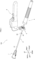
- the safety needle assembly 100 includes a hub 1, a cannula 2, a collar 3, a protector 4 and a sheath 5. Note an assembly having no protector 4 is also called a "safety needle assembly 100", as described hereinafter.
- the cannula 2 is connected with the hub 1 in a general method, for example, using an epoxy resin.
- the cannula 2 includes a proximal end 21 connected with a distal end of the hub 1 and a distal end 22 having a blade surface 20. Note it is preferable to respectively mold the hub 1, the collar 3, the protector 4 and the sheath 5 as one-piece parts.
- the present embodiment is not limited to the above mentioned method, and a variety of methods can be applied.
- the collar 3 is to be fitted with the hub 1 at a predetermined position. Further, the protector 4 is guided by the hub 1 to be fitted with the collar 3 and/or the hub 1, thereby to cover the cannula 2 at the fitting. Moreover, the sheath 5 is to be fitted with the collar 3 so that the sheath 5 can pivot on the collar 3.
- the hub 1 includes a distal end 10 and a proximal end 11 connected with a syringe (not shown in FIG. 2 ).
- a through hole 12 extends along the entire length of the hub 1 in a longitudinal direction (or front-back direction).
- the through hole 12 has apertures at both distal end 10 and proximal end 11 thereof.
- a distal end 21 of the cannula 2 in FIG. 1 is fitted and fixed with the inside of the through hole 12 at the distal end 10 of the hub 1 by using an epoxy resin. Accordingly, a lumen extending along the entire length of the cannula 2 is communicated with the through hole 12 inside the hub 1.
- the distal end 10 of the hub 1 comprises a plurality of ribs 13 in a shape resembling a series of steps, with extending in a longitudinal direction.
- the ribs 13 facilitate the collar 3 to be fitted with the hub 1 in a coaxial manner (or having central axis "c" be coaxial).
- a surface of the hub 1 includes a plurality of protrusions 14 projecting from a circumferential outside surface of the hub 1 to an outer side thereof in a radial direction.
- a recessed ring region 15 is located at a distal side of the protrusions 14. Accordingly, stage parts 16 and 17 neighboring the recessed ring region 15 have larger external diameters than the recessed ring region 15.
- the proximal end 11 of the hub 1 has a flange 18 projecting to an outer side of the hub 1 in a radial direction.
- the flange 18 is engaged with, for example, a distal end of a syringe body (not shown).
- the engagement allows the hub 1 to be connected with the syringe body (not shown).
- This connection step may be performed by a known method, for example, by engaging the flange 18 with a screw (or female screw) located at a distal end of the syringe body (not shown).
- the collar 3 has an outline in a circular shape, having a proximal end 38 and a distal end 34.
- the collar 3 further includes a through hole 39 for the attachment to the hub 1.
- an inside surface of the collar 3 has a plurality of protrusions 301 projecting to the internal side. Those protrusions 301 projecting to the internal side are engaged with the protrusions 14 of the hub 1. This engagement enables the collar 3 to be unratatably fixed onto the hub 1.
- the collar 3 includes a ring-shaped ridge 302 on an inner surface thereof.
- the ring-shaped ridge 302 is spread over the whole circumference at the inner peripheral side of the through hole 39.
- the ring-shaped ridge 302 is seated onto the recessed ring region 15 of the hub 1. Therefore, the ring-shaped ridge 302 has a smaller internal diameter than the external diameters of the two stages 16 and 17 directly neighboring to the recessed ring region 15 of the hub 1.
- the ring-shaped ridge 302 has a substantially equal internal diameter to the external diameter of the recessed ring region 15 of the hub 1.
- the ring-shaped ridge 302 projecting to the internal side in the radial diameter is shown as a consecutive ring-shaped ridge.
- the ring-shaped ridge 302 may be formed, as comprised of a plurality of separated segments, each of which extends along a part of the inner circumference of the collar 3.
- the collar 3 has a pair of ears 31 (or sheath attachment part) projecting to the external side in the radial direction.
- the upper half of the ear 31 has a shape formed by halving a substantially cylindrical shape lying on the side.
- the ear 31 includes an ear hole 33 with a cylindrical shape to which a pin 540 of the sheath 5 (as described hereinafter) is housed, and a chamfer 32.
- the chamfer 32 is arranged at an upper portion at the internal side of the ear 31, as shown in FIGS. 3A and 3B .
- the pin 540 of the sheath 5 passes along the chamfer 32, thereby to be housed in the ear hole 33.
- a pair of ears 31 enables the sheath 5 to be rotatably attached to the collar 3. More specifically, the chamfers 32 facilitate a pair of pins 540 of the sheath 5 to be respectively attached to the pair of ears 31 of the collar 3. Further, when the pair of pins 540 is attached to the pair of ears 31, the pair of ears 31 slightly bends toward the external direction so that the ears 31 are estranged each other. Moreover, a thickness of the ear 31 may be appropriately determined by considering the strength for resistance to damage, and the flexibility for easier attachment of the sheath 5.
- the collar 3 includes a ring-shaped ridge 36 projecting to the external side in the radial direction.
- the ring-shaped ridge 36 is a component for seating the protector 4.
- the collar 3 further includes a pair of sheath fixing protrusions 35.
- the sheath fixing protrusion 35 has a substantially triangle shape, and is arranged at the opposite side of the ear 31.
- the sheath fixing protrusion 35 further includes a groove 37 which is to be engaged with a wing wall 53 (or cannula fixing part) of the sheath 5.
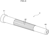
- the protector 4 is formed as a hollow member with an elongated cylindrical shape, including a distal end 40 and a proximal end 41.
- the protector 4 is opened at the proximal end 41 and closed at the distal end 41.
- a plurality of ribs 42 are arranged in a longitudinal direction at a middle portion of the external surface of the protector 4, so that a user can easily hold the protector 4.
- the protector 4 is arranged at the position to cover the cannula 2. This arrangement allows the protector 4 to cover up the distal end of the cannula 2. At that time, the protector 4 is fixed onto the collar 3 and/or the hub 1. Further, the protector 4 can be detachably pivoted so as to expose the distal end 22 of the cannula 2. Note a seating face (not shown) for the collar 3 may be arranged inside the protector 4 at the proximal end 41 thereof.
- the sheath 5 includes a proximal end 501 and a distal end 521, and is formed as an elongated member in the whole body.
- the sheath 5 includes an opening 58 extending along at least a portion of the longitudinal extent of the sheath 5.
- the opening 58 is an internal space of the sheath 5.
- the opening 58 of the sheath 5 extends along the entire length in the longitudinal direction.
- the proximal end 501 is opened in the longitudinal direction of the sheath 5, while the distal end 521 is closed in the longitudinal direction of the sheath 5.
- the sheath 5 includes finger guiding parts 50, 51 and a distal part 52, which are composed of a pair of side walls and a back wall.
- a circular recess 500 is arranged at the back wall of the finger guiding part 50.
- the circular recess 500 is used as a finger guiding region to which a finger of a user operating the sheath 5 contacts.
- the back wall of the finger guiding part 51 is formed as a slope descending to the front portion, in a stepped shape. On the slope, protrusions 510 and recesses 511 are repeatedly arranged so as to increase the friction against a user's finger.
- the back wall of the distal part 52 includes a protrusive stopper 55 which prevents the user's finger of pushing the sheath 5 from further moving toward the distal side of the sheath 5.
- the back wall of the distal part 52 includes a hole 520 which is formed when a locking tab 57 (or cannula fixing part) is molded.
- the stopper 55 is arranged at the vicinity of the center portion in the longitudinal direction, or at the position closer to the distal end side of the sheath 5, so that a larger moment is generated to smoothly pivot the sheath 5, when a user pushes the sheath 5 by a finger.
- the sheath 5 includes a collar connection mechanism 54 (or attachment part) having a pair of cylindrical pins 540.
- the pair of pins 540 is to be attached to the ear holes 33 of the ears 31 at the collar 3, so as to rotatably connect the sheath 5 with the collar 3.
- each pin 540 is chamfered in order to facilitate the above mentioned connection.
- a pair of wing walls 53 is arranged at the proximal end side of the finger guiding part 50. Inside the wing wall 53, a slope 530 is provided in the direction toward the proximal end 501. The slope 530 allows the sheath 5 to be easily attached to the collar 3 (that is, by relatively small force). Further, at the front side of the wing wall 53, is arranged a groove 531 (or cannula fixing part) which fits with the sheath fixing protrusion 35 of the collar 3.
- a groove 531 or cannula fixing part
- An opening 58 of the sheath 5 has a locking tab 57.
- the locking tab 57 is formed by a punching portion of the back wall of the distal part 52 and protrudes inside from the side wall located inside the opening 58.
- the locking tab 57 is to be bent when the cannula 2 is introduced into the opening 58. This allows the cannula 2 to move past the side of the locking tab 57.
- the locking tab 57 persistently locks the cannula 2 thus moved past the side of the tab 57 by preventing the cannula 2 from moving back. This locking occurs automatically in the above mentioned movement.
- this permanent locking of the cannula 2 fixed inside the sheath 5 can be achieved once the cannula 2 has been introduced into the opening 58 thereby to move past the side of the locking tab 57.
- the rib 56 positions the cannula 2 in the left-and right direction thereof when the cannula 2 is introduced into the opening 58.
- FIG. 6 shows the safety needle assembly 100 thus assembled by the respective components.
- the safety needle assembly 100 thus assembled may be packaged in a blister packaging or the like in the state of FIG. 6 , or may be packaged after the assembly 100 is connected with a syringe (not shown).
- FIGS. 6 and 7 a method for using the safety needle assembly 100 will be explained in case a user exposes the cannula 2 from the assembly 100 as shown in FIG. 5 .
- a user pivots the sheath 5 to be apart from the protector 4 so as to remove the protector 4.
- the user After the sheath 5 is pivoted, the user removes the protector 4 and exposes the cannula 2 (see FIG. 7 ). In this state, the user can use the cannula 2 (for example, to use the cannula 2 for collecting blood from a patient).
- FIGS. 7 to 9 a method for using the safety needle assembly 100 will be explained in case a user houses the cannula 2 inside the sheath 5 of the assembly 100 in the state of FIG. 7 .
- the user pivots the sheath 5 toward the cannula 2 thereby to have the safety needle assembly 100 be in the state of FIG. 8 .
- the user pushes the back wall of the finger guiding part 51 by a finger against the sheath 5.
- This allows the sheath 5 to be further pivoted toward the cannula 2 as shown in FIGS. 9A and 9B .
- the cannula 2 moves past the side of the locking tab 57 to be engaged with the locking tab 57, and the pair of sheath fixing protrusions 35 of the collar 3 is respectively engaged with the corresponding grooves 531 of the sheath 5.
- the cannula 2 is locked inside the sheath 5. That is, at this timing, the cannula 2 is covered by the sheath 5, and further is locked inside the sheath 5.
- the safety needle assembly 100 in the present embodiment enables the high safety due to the mechanism thereof (that is, securing the lower probability that a user erroneously stings the cannula 2 into a body). Further, this also enables the high operability to be realized due to the structure thereof that the sheath 5 has the stopper 55 at the vicinity of the central portion in the longitudinal direction of the sheath 5, or at the position closer to the distal end side than the central portion of the sheath 5.
- the above mentioned positioning of the stopper 55 allows a user to push the sheath 5 by a user's finger at a distal side from the fulcrum (or at the position of the pins 540 of the sheath 5), resulting in generation of a larger moment which enables the sheath 5 to be pivoted by relatively smaller force.
- the pair of wing walls 52 each having a slope 530 and a groove 531 in the sheath 5 enables the high operability to be realized. That is, the wing walls 53 projecting from the body of the sheath 5 are easy to be bent outward, and the slopes 530 facilitate the sheath fixing protrusions 35 to be introduced of the collar 3 into the grooves 531. Further, the grooves 531 allow the sheath fixing protrusions 35 to be fixed therein. Those mechanisms enable the sheath fixing protrusions 35 of the collar 3 to be fitted and fixed in the grooves 531 of the wing walls 53 of the sheath 5 with relatively small force when a user pushes the sheath 5 by a user's finger.
- a user can pivot the sheath 5 by pushing not only the slope provided with a plurality of protrusions 510 and recesses 511 having large friction but also the circular recess 500 to which a user's finger easily fits. Accordingly, this allows the high operability to be realized.
- the cannula 2 introduced inside the opening 58 of the sheath 5 is locked by the locking tab 57 besides the grooves 531 of the wing walls 53, allowing it less probable that the cannula 2 is exposed after being housed inside the sheath 5. That is, this makes the safety higher. Further, the locking tab 57 is easily molded, allowing the cannula fixing part to be formed at lower cost.
- each ear 31 of the collar 3 has a chamfer inside the ear 31, whereby the sheath is attached to the collar 3 through the chamfer, allowing the attachment to need relatively small force.
- the pair of sheath fixing protrusions 35 of the collar 3 is formed respectively in a substantially triangle having a groove 37, which is made in a simple structure.
- different sheaths 5 corresponding to the respective lengths may be used in the present invention.
Landscapes
- Health & Medical Sciences (AREA)
- Engineering & Computer Science (AREA)
- Heart & Thoracic Surgery (AREA)
- Vascular Medicine (AREA)
- Anesthesiology (AREA)
- Biomedical Technology (AREA)
- Environmental & Geological Engineering (AREA)
- Hematology (AREA)
- Life Sciences & Earth Sciences (AREA)
- Animal Behavior & Ethology (AREA)
- General Health & Medical Sciences (AREA)
- Public Health (AREA)
- Veterinary Medicine (AREA)
- Infusion, Injection, And Reservoir Apparatuses (AREA)
Claims (3)
- Ensemble aiguille de sécurité (100) doté d'un fourreau (5), comprenant :une embase (1) comprenant une extrémité proximale (11) conçue pour être raccordée à une seringue, et une extrémité distale (12) ;une canule (2) comprenant une extrémité proximale (21) se raccordant à l'extrémité distale (12) de l'embase (1), une lumière s'étendant dans une direction longitudinale, et une extrémité distale (22) ;un collier (3) fixé à l'embase (1), comprenant une partie de fixation de fourreau (31) et une paire de protubérances de fixation de fourreau (35) ;un élément de protection (4) couvrant l'extrémité distale de la canule (2) en étant fixé à l'embase (1) ou au collier (3), et étant détachable pour faire apparaître l'extrémité distale de la canule (2) ; etune ouverture (58) s'étendant partiellement le long d'au moins une direction longitudinale du fourreau (5) afin de loger la canule (2), dans lequelle fourreau (5) comprend en outre :une partie de fixation de canule (531) composée de rainures (37) dans lesquelles des protubérances de fixation de fourreau (35) sont ajustées respectivement lorsque la canule (2) est logée dans l'ouverture (58), et une paire de parois d'ailes (53) dont chacune est pourvue d'une pente (530) disposée à l'intérieur d'une paroi d'aile correspondante (53) dans une direction allant des rainures (37) à l'extrémité proximale du fourreau (5) ; etune partie de fixation (54) supportant de manière rotative le fourreau (5) dans une direction du logement de la canule (2) lorsque l'élément de protection (4) est détaché pour faire apparaître l'extrémité distale de la canule (2), la partie de fixation (54) étant fixée à la partie de fixation de fourreau (31) du collier (3),caractérisé en ce quela partie de fixation de canule (531) dans laquelle sont ajustées les protubérances de fixation de fourreau (35) du collier (3) est disposée à l'avant de la paroi d'aile (53) présentant chacune l'inclinaison (530).
- Ensemble aiguille de sécurité selon la revendication 1, dans lequel une partie de fixation du fourreau (5) est constituée de broches cylindriques (540), et une partie de fixation de fourreau du collier (3) est constituée d'oreilles saillantes (31) comprenant une paire de trous traversants (33) dont chacun loge la broche cylindrique (540), et de chanfreins internes dont chacun reçoit la broche cylindrique (540).
- Ensemble aiguille de sécurité (100) selon la revendication 1, dans lequel les protubérances de fixation de fourreau (35) du collier (3) ont respectivement une forme sensiblement triangulaire et sont disposées en une position opposée à la partie de fixation de fourreau (31), les protubérances de fixation de fourreau (35) comportant des rainures (37) dans lesquelles les parois d'ailes (53) de la partie de fixation de canule (531) sont ajustées respectivement.
Applications Claiming Priority (3)
| Application Number | Priority Date | Filing Date | Title |
|---|---|---|---|
| JP2011028075 | 2011-02-14 | ||
| PCT/JP2012/053136 WO2012111560A1 (fr) | 2011-02-14 | 2012-02-10 | Ensemble d'aiguille de sécurité |
| EP12747609.1A EP2676693B1 (fr) | 2011-02-14 | 2012-02-10 | Ensemble d'aiguille de sécurité |
Related Parent Applications (1)
| Application Number | Title | Priority Date | Filing Date |
|---|---|---|---|
| EP12747609.1A Division EP2676693B1 (fr) | 2011-02-14 | 2012-02-10 | Ensemble d'aiguille de sécurité |
Publications (2)
| Publication Number | Publication Date |
|---|---|
| EP3603707A1 EP3603707A1 (fr) | 2020-02-05 |
| EP3603707B1 true EP3603707B1 (fr) | 2023-06-21 |
Family
ID=46672485
Family Applications (2)
| Application Number | Title | Priority Date | Filing Date |
|---|---|---|---|
| EP19193274.8A Active EP3603707B1 (fr) | 2011-02-14 | 2012-02-10 | Ensemble d'aiguille de sécurité |
| EP12747609.1A Active EP2676693B1 (fr) | 2011-02-14 | 2012-02-10 | Ensemble d'aiguille de sécurité |
Family Applications After (1)
| Application Number | Title | Priority Date | Filing Date |
|---|---|---|---|
| EP12747609.1A Active EP2676693B1 (fr) | 2011-02-14 | 2012-02-10 | Ensemble d'aiguille de sécurité |
Country Status (9)
| Country | Link |
|---|---|
| US (2) | US9861761B2 (fr) |
| EP (2) | EP3603707B1 (fr) |
| JP (1) | JP5896927B2 (fr) |
| CN (1) | CN103338803B (fr) |
| AU (2) | AU2012218684B2 (fr) |
| BR (1) | BR112013020087B1 (fr) |
| CA (1) | CA2827415C (fr) |
| MY (1) | MY162389A (fr) |
| WO (1) | WO2012111560A1 (fr) |
Families Citing this family (24)
| Publication number | Priority date | Publication date | Assignee | Title |
|---|---|---|---|---|
| US10639430B2 (en) | 2010-11-22 | 2020-05-05 | B. Braun Melsungen Ag | Hinged shield assemblies and related methods |
| EP3603707B1 (fr) | 2011-02-14 | 2023-06-21 | Terumo Kabushiki Kaisha | Ensemble d'aiguille de sécurité |
| AT513668B1 (de) * | 2012-11-29 | 2014-08-15 | Greiner Bio One Gmbh | Sicherheitsbaugruppe für die Medizintechnik |
| CN105979991B (zh) * | 2013-12-05 | 2020-03-03 | 梅捷医药有限公司 | 安全夹具 |
| CN203790382U (zh) * | 2014-03-13 | 2014-08-27 | 扬州美德莱国际贸易有限公司 | 一种一次性使用安全注射针 |
| EP2923717A1 (fr) * | 2014-03-28 | 2015-09-30 | Sanofi-Aventis Deutschland GmbH | Dispositif d'aiguille de sécurité |
| JPWO2016002389A1 (ja) * | 2014-07-02 | 2017-04-27 | テルモ株式会社 | 安全針アセンブリ |
| AU2015308583B2 (en) * | 2014-08-29 | 2019-11-28 | Medical Components, Inc. | Huber safety needle |
| GB2532979A (en) * | 2014-12-04 | 2016-06-08 | Owen Mumford Ltd | Needle assemblies |
| US20160158458A1 (en) * | 2014-12-07 | 2016-06-09 | Wuxi Yushou Medical Appliances Co., Ltd. | Safe Injection Device Capable of Locking Needle |
| RU2017132494A (ru) * | 2015-02-19 | 2019-03-19 | Александр ЛИ | Стоматологический шприц со стабилизатором для съемной иглы |
| US10029049B2 (en) | 2015-03-19 | 2018-07-24 | B. Braun Melsungen Ag | Hinged shield assemblies and related methods |
| US20160317755A1 (en) * | 2015-04-30 | 2016-11-03 | Hsien-Tsung Wang | Safety syringe |
| TWI583422B (zh) * | 2015-12-31 | 2017-05-21 | Qing-Xiang Wei | Needle safety device for injection needle |
| CN106390238A (zh) * | 2016-11-02 | 2017-02-15 | 扬州美德莱医疗用品有限公司 | 一次性使用安全胰岛素注射器 |
| WO2018101482A1 (fr) | 2016-12-02 | 2018-06-07 | ニプロ株式会社 | Ensemble aiguille et dispositif d'aiguille comportant ledit ensemble |
| TWI645874B (zh) * | 2017-06-07 | 2019-01-01 | 魏慶祥 | 注射針之安全護蓋及其基座 |
| CN109172939A (zh) * | 2018-10-16 | 2019-01-11 | 宁波大学医学院附属医院 | 一种一次性医用安全针 |
| WO2020216918A1 (fr) | 2019-04-26 | 2020-10-29 | Becton Dickinson France | Couvre-aiguille à contre-dépouille |
| USD1029248S1 (en) * | 2019-07-18 | 2024-05-28 | Metier Medical Limited | Safety needle |
| USD968591S1 (en) * | 2020-12-14 | 2022-11-01 | Expressions Design Studio, LLC | Safety needle |
| USD969314S1 (en) * | 2020-12-14 | 2022-11-08 | Expressions Design Studio, LLC | Blood collection safety needle |
| US20260021257A1 (en) | 2022-10-13 | 2026-01-22 | UNISIS Coporation | Injection needle cover and injection needle assembly |
| WO2024181366A1 (fr) * | 2023-03-01 | 2024-09-06 | テルモ株式会社 | Injecteur à aiguille fixe |
Family Cites Families (45)
| Publication number | Priority date | Publication date | Assignee | Title |
|---|---|---|---|---|
| US4832696A (en) * | 1987-03-05 | 1989-05-23 | Luther Medical Products, Inc. | Assembly of needle and protector |
| GB8818162D0 (en) * | 1988-07-29 | 1988-09-01 | Olliffe R M | Hypodermic syringe |
| US5188611A (en) * | 1990-05-31 | 1993-02-23 | Orgain Peter A | Safety sheath for needles, sharp instruments and tools |
| US5623762A (en) * | 1994-08-17 | 1997-04-29 | White; Jennifer A. | Hypodermic needle disposal apparatus |
| US5643219A (en) | 1994-09-23 | 1997-07-01 | Burns; James A. | Shielded needle assembly |
| CA2157999C (fr) * | 1994-09-23 | 1999-08-03 | Robert B. Odell | Dispositif protecteur a rotation manuelle pour element de percage |
| CA2118458C (fr) * | 1994-10-19 | 2006-01-03 | Joe Debreczeni | Assemblage d'aiguille pour seringue |
| US5925020A (en) * | 1994-11-22 | 1999-07-20 | Becton, Dickinson And Company | Needle point barrier |
| US5599313A (en) * | 1995-02-03 | 1997-02-04 | Becton, Dickinson And Company | Needle shield assembly having safety indication features |
| US5599318A (en) * | 1995-08-29 | 1997-02-04 | Becton, Dickinson And Company | Needle shield assembly having a releasable lock |
| US5509907A (en) * | 1996-03-17 | 1996-04-23 | Med-Safe Products, Inc. | Syringe needle guard assembly |
| US5913846A (en) * | 1996-06-13 | 1999-06-22 | Becton, Dickinson And Company | Shielded needle assembly |
| US5681295A (en) * | 1996-07-03 | 1997-10-28 | Becton, Dickinson And Company | Needle shield assembly having a single-use cannula lock |
| US5669889A (en) * | 1996-07-03 | 1997-09-23 | Becton, Dickinson And Company | Needle shield assembly having a single-use lock |
| US5746726A (en) * | 1996-08-23 | 1998-05-05 | Becton, Dickinson And Company | Shielded needle assembly |
| US5733265A (en) * | 1996-09-25 | 1998-03-31 | Becton Dickinson And Company | Shielded needle assembly |
| US6454746B1 (en) * | 1997-06-04 | 2002-09-24 | Eli Lilly And Company | Medication delivery apparatus |
| US6120482A (en) * | 1997-09-09 | 2000-09-19 | Becton, Dickinson And Company | Pivotable guard for shielding a needle |
| US6298541B1 (en) | 1998-08-28 | 2001-10-09 | Becton, Dickinson And Company | Method for making a safety shield assembly and related combinations thereof |
| US7223258B2 (en) * | 1998-08-28 | 2007-05-29 | Becton Dickinson And Company | Safety shield assembly |
| US6575941B1 (en) * | 1998-12-24 | 2003-06-10 | Safety Medical Supply International, Inc. | Permanent locking mechanism for sharp-instrument safety guard |
| US6042570A (en) * | 1999-02-11 | 2000-03-28 | Dsu Medical Corporation | Needle point protection sheath |
| US6837877B2 (en) * | 1999-08-23 | 2005-01-04 | Becton, Dickinson And Company | Safety shield assembly |
| US6699217B2 (en) * | 1999-08-23 | 2004-03-02 | Becton, Dickinson And Company | Safety needle assembly |
| US6309376B1 (en) * | 1999-10-07 | 2001-10-30 | Sims Portex, Inc. | Safety device for intravenous infusion needles |
| US8226617B2 (en) * | 1999-11-04 | 2012-07-24 | Tyco Healthcare Group Lp | Safety shield apparatus and mounting structure for use with medical needle devices |
| US6582397B2 (en) * | 2001-06-19 | 2003-06-24 | Portex, Inc. | Needle safety device with antiremoval protection |
| US6984223B2 (en) * | 2001-11-13 | 2006-01-10 | Becton, Dickinson And Company | Needle safety device |
| CA2422521A1 (fr) * | 2002-03-20 | 2003-09-20 | Kirk D. Swenson | Ensemble aiguille-gaine |
| US20040010233A1 (en) * | 2002-04-16 | 2004-01-15 | Birger Hjertman | System and a method for modification of a device and a device suitable for modification |
| US6719737B2 (en) | 2002-05-13 | 2004-04-13 | Terumo Medical Corporation | Safety needle assembly |
| US7201736B2 (en) * | 2003-08-28 | 2007-04-10 | Smiths Medical Asd, Inc. | Needle protection assembly |
| US7250038B2 (en) * | 2003-09-09 | 2007-07-31 | Smiths Medical Asd, Inc. | Fixed needle syringe with protective needle housing |
| US7635352B2 (en) * | 2005-05-27 | 2009-12-22 | Becton, Dickinson And Company | Catheter and introducer needle assembly with needle shield |
| CA2625030A1 (fr) * | 2005-10-17 | 2007-04-26 | Becton, Dickinson And Company | Ensemble de poutres blindables contenant des charnieres de contrainte reduite et procedes de fabrication |
| US8057431B2 (en) * | 2006-12-21 | 2011-11-15 | B. Braun Melsungen Ag | Hinged cap for needle device |
| US8038654B2 (en) * | 2007-02-26 | 2011-10-18 | Becton, Dickinson And Company | Syringe having a hinged needle shield |
| WO2009016234A1 (fr) * | 2007-08-01 | 2009-02-05 | Süddeutsche Feinmechanik GmbH | Dispositif de canule équipé d'une protection d'aiguille pivotante |
| WO2010059502A2 (fr) * | 2008-11-18 | 2010-05-27 | B. Braun Melsungen Ag | Ensemble d'étuis à charnière et procédés connexes |
| US10639430B2 (en) * | 2010-11-22 | 2020-05-05 | B. Braun Melsungen Ag | Hinged shield assemblies and related methods |
| EP3603707B1 (fr) * | 2011-02-14 | 2023-06-21 | Terumo Kabushiki Kaisha | Ensemble d'aiguille de sécurité |
| US10092230B2 (en) * | 2011-04-29 | 2018-10-09 | Stat Medical Devices, Inc. | Fluid collection/injection device having safety needle assembly/cover and safety system and method |
| US20120323216A1 (en) * | 2011-06-16 | 2012-12-20 | Koh Lawrence R | Needleshield assembly |
| US10029049B2 (en) * | 2015-03-19 | 2018-07-24 | B. Braun Melsungen Ag | Hinged shield assemblies and related methods |
| GB201507981D0 (en) * | 2015-05-11 | 2015-06-24 | Owen Mumford Ltd | Needle assemblies |
-
2012
- 2012-02-10 EP EP19193274.8A patent/EP3603707B1/fr active Active
- 2012-02-10 MY MYPI2013701420A patent/MY162389A/en unknown
- 2012-02-10 WO PCT/JP2012/053136 patent/WO2012111560A1/fr not_active Ceased
- 2012-02-10 JP JP2012557931A patent/JP5896927B2/ja active Active
- 2012-02-10 EP EP12747609.1A patent/EP2676693B1/fr active Active
- 2012-02-10 AU AU2012218684A patent/AU2012218684B2/en active Active
- 2012-02-10 BR BR112013020087-1A patent/BR112013020087B1/pt active IP Right Grant
- 2012-02-10 CN CN201280006699.1A patent/CN103338803B/zh active Active
- 2012-02-10 CA CA2827415A patent/CA2827415C/fr active Active
-
2013
- 2013-08-14 US US13/966,892 patent/US9861761B2/en active Active
-
2016
- 2016-08-12 AU AU2016213847A patent/AU2016213847B2/en active Active
-
2017
- 2017-12-01 US US15/828,740 patent/US11202868B2/en active Active
Also Published As
| Publication number | Publication date |
|---|---|
| CN103338803A (zh) | 2013-10-02 |
| MY162389A (en) | 2017-06-15 |
| EP2676693B1 (fr) | 2019-09-11 |
| BR112013020087B1 (pt) | 2020-12-15 |
| US20180085534A1 (en) | 2018-03-29 |
| BR112013020087A2 (pt) | 2016-10-25 |
| CA2827415A1 (fr) | 2012-08-23 |
| US20130331793A1 (en) | 2013-12-12 |
| CN103338803B (zh) | 2016-11-09 |
| AU2012218684A1 (en) | 2013-10-03 |
| JPWO2012111560A1 (ja) | 2014-07-07 |
| JP5896927B2 (ja) | 2016-03-30 |
| EP2676693A1 (fr) | 2013-12-25 |
| WO2012111560A1 (fr) | 2012-08-23 |
| EP2676693A4 (fr) | 2017-06-28 |
| AU2016213847A1 (en) | 2016-09-01 |
| CA2827415C (fr) | 2018-10-23 |
| AU2016213847B2 (en) | 2017-06-29 |
| US9861761B2 (en) | 2018-01-09 |
| EP3603707A1 (fr) | 2020-02-05 |
| AU2012218684B2 (en) | 2016-09-08 |
| US11202868B2 (en) | 2021-12-21 |
Similar Documents
| Publication | Publication Date | Title |
|---|---|---|
| EP2676693B1 (fr) | Ensemble d'aiguille de sécurité | |
| EP1506029B1 (fr) | Ensemble aiguille de sureté | |
| US20160220766A1 (en) | Safety needle assembly | |
| US7722572B2 (en) | Safety needle assembly | |
| EP1459781B1 (fr) | Capuchon de protection pour aiguille à ailettes | |
| CN106999678A (zh) | 针罩拉出帽组件 | |
| JP2013099584A (ja) | 注射針装置 | |
| JP2004522552A (ja) | ヒンジのある針シールドと可撓性のカニューレロックを有する針シールド組立て品 | |
| CN115697443B (zh) | 用于防止医疗注射装置的针造成针刺伤害的安全装置 | |
| JP4844259B2 (ja) | 針組立体の製造方法 | |
| HK1187843A (en) | Safety needle assembly | |
| HK1187843B (en) | Safety needle assembly |
Legal Events
| Date | Code | Title | Description |
|---|---|---|---|
| PUAI | Public reference made under article 153(3) epc to a published international application that has entered the european phase |
Free format text: ORIGINAL CODE: 0009012 |
|
| STAA | Information on the status of an ep patent application or granted ep patent |
Free format text: STATUS: THE APPLICATION HAS BEEN PUBLISHED |
|
| AC | Divisional application: reference to earlier application |
Ref document number: 2676693 Country of ref document: EP Kind code of ref document: P |
|
| AK | Designated contracting states |
Kind code of ref document: A1 Designated state(s): AL AT BE BG CH CY CZ DE DK EE ES FI FR GB GR HR HU IE IS IT LI LT LU LV MC MK MT NL NO PL PT RO RS SE SI SK SM TR |
|
| STAA | Information on the status of an ep patent application or granted ep patent |
Free format text: STATUS: REQUEST FOR EXAMINATION WAS MADE |
|
| 17P | Request for examination filed |
Effective date: 20200629 |
|
| RBV | Designated contracting states (corrected) |
Designated state(s): AL AT BE BG CH CY CZ DE DK EE ES FI FR GB GR HR HU IE IS IT LI LT LU LV MC MK MT NL NO PL PT RO RS SE SI SK SM TR |
|
| GRAP | Despatch of communication of intention to grant a patent |
Free format text: ORIGINAL CODE: EPIDOSNIGR1 |
|
| STAA | Information on the status of an ep patent application or granted ep patent |
Free format text: STATUS: GRANT OF PATENT IS INTENDED |
|
| INTG | Intention to grant announced |
Effective date: 20230224 |
|
| GRAS | Grant fee paid |
Free format text: ORIGINAL CODE: EPIDOSNIGR3 |
|
| GRAA | (expected) grant |
Free format text: ORIGINAL CODE: 0009210 |
|
| STAA | Information on the status of an ep patent application or granted ep patent |
Free format text: STATUS: THE PATENT HAS BEEN GRANTED |
|
| AC | Divisional application: reference to earlier application |
Ref document number: 2676693 Country of ref document: EP Kind code of ref document: P |
|
| AK | Designated contracting states |
Kind code of ref document: B1 Designated state(s): AL AT BE BG CH CY CZ DE DK EE ES FI FR GB GR HR HU IE IS IT LI LT LU LV MC MK MT NL NO PL PT RO RS SE SI SK SM TR |
|
| REG | Reference to a national code |
Ref country code: CH Ref legal event code: EP |
|
| REG | Reference to a national code |
Ref country code: DE Ref legal event code: R096 Ref document number: 602012079783 Country of ref document: DE |
|
| REG | Reference to a national code |
Ref country code: AT Ref legal event code: REF Ref document number: 1580439 Country of ref document: AT Kind code of ref document: T Effective date: 20230715 |
|
| REG | Reference to a national code |
Ref country code: IE Ref legal event code: FG4D |
|
| REG | Reference to a national code |
Ref country code: LT Ref legal event code: MG9D |
|
| REG | Reference to a national code |
Ref country code: NL Ref legal event code: MP Effective date: 20230621 |
|
| PG25 | Lapsed in a contracting state [announced via postgrant information from national office to epo] |
Ref country code: SE Free format text: LAPSE BECAUSE OF FAILURE TO SUBMIT A TRANSLATION OF THE DESCRIPTION OR TO PAY THE FEE WITHIN THE PRESCRIBED TIME-LIMIT Effective date: 20230621 Ref country code: NO Free format text: LAPSE BECAUSE OF FAILURE TO SUBMIT A TRANSLATION OF THE DESCRIPTION OR TO PAY THE FEE WITHIN THE PRESCRIBED TIME-LIMIT Effective date: 20230921 |
|
| REG | Reference to a national code |
Ref country code: AT Ref legal event code: MK05 Ref document number: 1580439 Country of ref document: AT Kind code of ref document: T Effective date: 20230621 |
|
| PG25 | Lapsed in a contracting state [announced via postgrant information from national office to epo] |
Ref country code: RS Free format text: LAPSE BECAUSE OF FAILURE TO SUBMIT A TRANSLATION OF THE DESCRIPTION OR TO PAY THE FEE WITHIN THE PRESCRIBED TIME-LIMIT Effective date: 20230621 Ref country code: NL Free format text: LAPSE BECAUSE OF FAILURE TO SUBMIT A TRANSLATION OF THE DESCRIPTION OR TO PAY THE FEE WITHIN THE PRESCRIBED TIME-LIMIT Effective date: 20230621 Ref country code: LV Free format text: LAPSE BECAUSE OF FAILURE TO SUBMIT A TRANSLATION OF THE DESCRIPTION OR TO PAY THE FEE WITHIN THE PRESCRIBED TIME-LIMIT Effective date: 20230621 Ref country code: LT Free format text: LAPSE BECAUSE OF FAILURE TO SUBMIT A TRANSLATION OF THE DESCRIPTION OR TO PAY THE FEE WITHIN THE PRESCRIBED TIME-LIMIT Effective date: 20230621 Ref country code: HR Free format text: LAPSE BECAUSE OF FAILURE TO SUBMIT A TRANSLATION OF THE DESCRIPTION OR TO PAY THE FEE WITHIN THE PRESCRIBED TIME-LIMIT Effective date: 20230621 Ref country code: GR Free format text: LAPSE BECAUSE OF FAILURE TO SUBMIT A TRANSLATION OF THE DESCRIPTION OR TO PAY THE FEE WITHIN THE PRESCRIBED TIME-LIMIT Effective date: 20230922 |
|
| PG25 | Lapsed in a contracting state [announced via postgrant information from national office to epo] |
Ref country code: FI Free format text: LAPSE BECAUSE OF FAILURE TO SUBMIT A TRANSLATION OF THE DESCRIPTION OR TO PAY THE FEE WITHIN THE PRESCRIBED TIME-LIMIT Effective date: 20230621 |
|
| PG25 | Lapsed in a contracting state [announced via postgrant information from national office to epo] |
Ref country code: SK Free format text: LAPSE BECAUSE OF FAILURE TO SUBMIT A TRANSLATION OF THE DESCRIPTION OR TO PAY THE FEE WITHIN THE PRESCRIBED TIME-LIMIT Effective date: 20230621 |
|
| PG25 | Lapsed in a contracting state [announced via postgrant information from national office to epo] |
Ref country code: ES Free format text: LAPSE BECAUSE OF FAILURE TO SUBMIT A TRANSLATION OF THE DESCRIPTION OR TO PAY THE FEE WITHIN THE PRESCRIBED TIME-LIMIT Effective date: 20230621 |
|
| PG25 | Lapsed in a contracting state [announced via postgrant information from national office to epo] |
Ref country code: IS Free format text: LAPSE BECAUSE OF FAILURE TO SUBMIT A TRANSLATION OF THE DESCRIPTION OR TO PAY THE FEE WITHIN THE PRESCRIBED TIME-LIMIT Effective date: 20231021 |
|
| PG25 | Lapsed in a contracting state [announced via postgrant information from national office to epo] |
Ref country code: SM Free format text: LAPSE BECAUSE OF FAILURE TO SUBMIT A TRANSLATION OF THE DESCRIPTION OR TO PAY THE FEE WITHIN THE PRESCRIBED TIME-LIMIT Effective date: 20230621 Ref country code: SK Free format text: LAPSE BECAUSE OF FAILURE TO SUBMIT A TRANSLATION OF THE DESCRIPTION OR TO PAY THE FEE WITHIN THE PRESCRIBED TIME-LIMIT Effective date: 20230621 Ref country code: RO Free format text: LAPSE BECAUSE OF FAILURE TO SUBMIT A TRANSLATION OF THE DESCRIPTION OR TO PAY THE FEE WITHIN THE PRESCRIBED TIME-LIMIT Effective date: 20230621 Ref country code: PT Free format text: LAPSE BECAUSE OF FAILURE TO SUBMIT A TRANSLATION OF THE DESCRIPTION OR TO PAY THE FEE WITHIN THE PRESCRIBED TIME-LIMIT Effective date: 20231023 Ref country code: IS Free format text: LAPSE BECAUSE OF FAILURE TO SUBMIT A TRANSLATION OF THE DESCRIPTION OR TO PAY THE FEE WITHIN THE PRESCRIBED TIME-LIMIT Effective date: 20231021 Ref country code: ES Free format text: LAPSE BECAUSE OF FAILURE TO SUBMIT A TRANSLATION OF THE DESCRIPTION OR TO PAY THE FEE WITHIN THE PRESCRIBED TIME-LIMIT Effective date: 20230621 Ref country code: EE Free format text: LAPSE BECAUSE OF FAILURE TO SUBMIT A TRANSLATION OF THE DESCRIPTION OR TO PAY THE FEE WITHIN THE PRESCRIBED TIME-LIMIT Effective date: 20230621 Ref country code: CZ Free format text: LAPSE BECAUSE OF FAILURE TO SUBMIT A TRANSLATION OF THE DESCRIPTION OR TO PAY THE FEE WITHIN THE PRESCRIBED TIME-LIMIT Effective date: 20230621 Ref country code: AT Free format text: LAPSE BECAUSE OF FAILURE TO SUBMIT A TRANSLATION OF THE DESCRIPTION OR TO PAY THE FEE WITHIN THE PRESCRIBED TIME-LIMIT Effective date: 20230621 |
|
| PG25 | Lapsed in a contracting state [announced via postgrant information from national office to epo] |
Ref country code: PL Free format text: LAPSE BECAUSE OF FAILURE TO SUBMIT A TRANSLATION OF THE DESCRIPTION OR TO PAY THE FEE WITHIN THE PRESCRIBED TIME-LIMIT Effective date: 20230621 |
|
| REG | Reference to a national code |
Ref country code: DE Ref legal event code: R097 Ref document number: 602012079783 Country of ref document: DE |
|
| PLBE | No opposition filed within time limit |
Free format text: ORIGINAL CODE: 0009261 |
|
| STAA | Information on the status of an ep patent application or granted ep patent |
Free format text: STATUS: NO OPPOSITION FILED WITHIN TIME LIMIT |
|
| PG25 | Lapsed in a contracting state [announced via postgrant information from national office to epo] |
Ref country code: DK Free format text: LAPSE BECAUSE OF FAILURE TO SUBMIT A TRANSLATION OF THE DESCRIPTION OR TO PAY THE FEE WITHIN THE PRESCRIBED TIME-LIMIT Effective date: 20230621 |
|
| PG25 | Lapsed in a contracting state [announced via postgrant information from national office to epo] |
Ref country code: SI Free format text: LAPSE BECAUSE OF FAILURE TO SUBMIT A TRANSLATION OF THE DESCRIPTION OR TO PAY THE FEE WITHIN THE PRESCRIBED TIME-LIMIT Effective date: 20230621 |
|
| 26N | No opposition filed |
Effective date: 20240322 |
|
| PG25 | Lapsed in a contracting state [announced via postgrant information from national office to epo] |
Ref country code: SI Free format text: LAPSE BECAUSE OF FAILURE TO SUBMIT A TRANSLATION OF THE DESCRIPTION OR TO PAY THE FEE WITHIN THE PRESCRIBED TIME-LIMIT Effective date: 20230621 Ref country code: IT Free format text: LAPSE BECAUSE OF FAILURE TO SUBMIT A TRANSLATION OF THE DESCRIPTION OR TO PAY THE FEE WITHIN THE PRESCRIBED TIME-LIMIT Effective date: 20230621 |
|
| PG25 | Lapsed in a contracting state [announced via postgrant information from national office to epo] |
Ref country code: MC Free format text: LAPSE BECAUSE OF FAILURE TO SUBMIT A TRANSLATION OF THE DESCRIPTION OR TO PAY THE FEE WITHIN THE PRESCRIBED TIME-LIMIT Effective date: 20230621 |
|
| REG | Reference to a national code |
Ref country code: CH Ref legal event code: PL |
|
| PG25 | Lapsed in a contracting state [announced via postgrant information from national office to epo] |
Ref country code: LU Free format text: LAPSE BECAUSE OF NON-PAYMENT OF DUE FEES Effective date: 20240210 |
|
| PG25 | Lapsed in a contracting state [announced via postgrant information from national office to epo] |
Ref country code: CH Free format text: LAPSE BECAUSE OF NON-PAYMENT OF DUE FEES Effective date: 20240229 |
|
| PG25 | Lapsed in a contracting state [announced via postgrant information from national office to epo] |
Ref country code: LU Free format text: LAPSE BECAUSE OF NON-PAYMENT OF DUE FEES Effective date: 20240210 Ref country code: CH Free format text: LAPSE BECAUSE OF NON-PAYMENT OF DUE FEES Effective date: 20240229 |
|
| PG25 | Lapsed in a contracting state [announced via postgrant information from national office to epo] |
Ref country code: BG Free format text: LAPSE BECAUSE OF FAILURE TO SUBMIT A TRANSLATION OF THE DESCRIPTION OR TO PAY THE FEE WITHIN THE PRESCRIBED TIME-LIMIT Effective date: 20230621 |
|
| PG25 | Lapsed in a contracting state [announced via postgrant information from national office to epo] |
Ref country code: BG Free format text: LAPSE BECAUSE OF FAILURE TO SUBMIT A TRANSLATION OF THE DESCRIPTION OR TO PAY THE FEE WITHIN THE PRESCRIBED TIME-LIMIT Effective date: 20230621 |
|
| REG | Reference to a national code |
Ref country code: BE Ref legal event code: MM Effective date: 20240229 |
|
| PG25 | Lapsed in a contracting state [announced via postgrant information from national office to epo] |
Ref country code: BE Free format text: LAPSE BECAUSE OF NON-PAYMENT OF DUE FEES Effective date: 20240229 |
|
| PG25 | Lapsed in a contracting state [announced via postgrant information from national office to epo] |
Ref country code: IE Free format text: LAPSE BECAUSE OF NON-PAYMENT OF DUE FEES Effective date: 20240210 |
|
| PG25 | Lapsed in a contracting state [announced via postgrant information from national office to epo] |
Ref country code: IE Free format text: LAPSE BECAUSE OF NON-PAYMENT OF DUE FEES Effective date: 20240210 Ref country code: BE Free format text: LAPSE BECAUSE OF NON-PAYMENT OF DUE FEES Effective date: 20240229 |
|
| PG25 | Lapsed in a contracting state [announced via postgrant information from national office to epo] |
Ref country code: CY Free format text: LAPSE BECAUSE OF FAILURE TO SUBMIT A TRANSLATION OF THE DESCRIPTION OR TO PAY THE FEE WITHIN THE PRESCRIBED TIME-LIMIT; INVALID AB INITIO Effective date: 20120210 |
|
| PG25 | Lapsed in a contracting state [announced via postgrant information from national office to epo] |
Ref country code: HU Free format text: LAPSE BECAUSE OF FAILURE TO SUBMIT A TRANSLATION OF THE DESCRIPTION OR TO PAY THE FEE WITHIN THE PRESCRIBED TIME-LIMIT; INVALID AB INITIO Effective date: 20120210 |
|
| PG25 | Lapsed in a contracting state [announced via postgrant information from national office to epo] |
Ref country code: TR Free format text: LAPSE BECAUSE OF FAILURE TO SUBMIT A TRANSLATION OF THE DESCRIPTION OR TO PAY THE FEE WITHIN THE PRESCRIBED TIME-LIMIT Effective date: 20230621 |
|
| PGFP | Annual fee paid to national office [announced via postgrant information from national office to epo] |
Ref country code: FR Payment date: 20251231 Year of fee payment: 15 |
|
| PGFP | Annual fee paid to national office [announced via postgrant information from national office to epo] |
Ref country code: GB Payment date: 20260106 Year of fee payment: 15 |
|
| PGFP | Annual fee paid to national office [announced via postgrant information from national office to epo] |
Ref country code: DE Payment date: 20251230 Year of fee payment: 15 |