EP3603816B1 - Tête de douche améliorée - Google Patents
Tête de douche améliorée Download PDFInfo
- Publication number
- EP3603816B1 EP3603816B1 EP19188990.6A EP19188990A EP3603816B1 EP 3603816 B1 EP3603816 B1 EP 3603816B1 EP 19188990 A EP19188990 A EP 19188990A EP 3603816 B1 EP3603816 B1 EP 3603816B1
- Authority
- EP
- European Patent Office
- Prior art keywords
- upper plate
- hole
- rib
- shower head
- protuberance
- Prior art date
- Legal status (The legal status is an assumption and is not a legal conclusion. Google has not performed a legal analysis and makes no representation as to the accuracy of the status listed.)
- Active
Links
Images





Classifications
-
- E—FIXED CONSTRUCTIONS
- E03—WATER SUPPLY; SEWERAGE
- E03C—DOMESTIC PLUMBING INSTALLATIONS FOR FRESH WATER OR WASTE WATER; SINKS
- E03C1/00—Domestic plumbing installations for fresh water or waste water; Sinks
- E03C1/02—Plumbing installations for fresh water
- E03C1/04—Water-basin installations specially adapted to wash-basins or baths
- E03C1/0404—Constructional or functional features of the spout
-
- B—PERFORMING OPERATIONS; TRANSPORTING
- B05—SPRAYING OR ATOMISING IN GENERAL; APPLYING FLUENT MATERIALS TO SURFACES, IN GENERAL
- B05B—SPRAYING APPARATUS; ATOMISING APPARATUS; NOZZLES
- B05B1/00—Nozzles, spray heads or other outlets, with or without auxiliary devices such as valves, heating means
- B05B1/14—Nozzles, spray heads or other outlets, with or without auxiliary devices such as valves, heating means with multiple outlet openings; with strainers in or outside the outlet opening
- B05B1/18—Roses; Shower heads
-
- B—PERFORMING OPERATIONS; TRANSPORTING
- B05—SPRAYING OR ATOMISING IN GENERAL; APPLYING FLUENT MATERIALS TO SURFACES, IN GENERAL
- B05B—SPRAYING APPARATUS; ATOMISING APPARATUS; NOZZLES
- B05B1/00—Nozzles, spray heads or other outlets, with or without auxiliary devices such as valves, heating means
- B05B1/30—Nozzles, spray heads or other outlets, with or without auxiliary devices such as valves, heating means designed to control volume of flow, e.g. with adjustable passages
- B05B1/3006—Nozzles, spray heads or other outlets, with or without auxiliary devices such as valves, heating means designed to control volume of flow, e.g. with adjustable passages the controlling element being actuated by the pressure of the fluid to be sprayed
-
- B—PERFORMING OPERATIONS; TRANSPORTING
- B05—SPRAYING OR ATOMISING IN GENERAL; APPLYING FLUENT MATERIALS TO SURFACES, IN GENERAL
- B05B—SPRAYING APPARATUS; ATOMISING APPARATUS; NOZZLES
- B05B15/00—Details of spraying plant or spraying apparatus not otherwise provided for; Accessories
- B05B15/50—Arrangements for cleaning; Arrangements for preventing deposits, drying-out or blockage; Arrangements for detecting improper discharge caused by the presence of foreign matter
Definitions
- the present invention relates to an improved shower head.
- shower heads of various type, shape and size are known. Generally, they consist of a lower plate, provided with water outlet holes, secured in a watertight manner to an upper plate provided with a water inlet hole, connected with suitable connections and pipes to a water supply faucet. A water collection chamber is defined between the lower plate and the upper plate. Securing of the two plates in a watertight manner can be obtained in various ways, both removably and irremovably. Removable securing of the two plates is typically obtained by means of screws, and with the interposing of appropriate gaskets. Irremovable securing is typically obtained by means of perimeter welding, for example by laser welding. In a possible embodiment, the water collection chamber is formed as a result of the drawn shape of the upper plate.
- a problem of shower heads consists of clogging of the water outlet holes caused by limescale build-up. This problem is particularly common in areas in which the water is hard or very hard, i.e., is rich in calcium and magnesium salts.
- nozzles made of silicone rubber or a similar material are normally inserted into the water outlet holes. By squeezing these nozzles after using the shower head, the water retained in the nozzles and in the water collection chamber above can be removed.
- the rubber nozzles can be formed as part of a mat to be inserted between the lower and upper plate, or can be formed individually, and as such inserted into the holes of the lower plate.
- Some systems currently present on the market provide for the use of safety caps positioned on the body of the shower head, which following an increase in the pressure above a threshold value are irreversibly deformed or are literally ejected from the body of the shower head freeing a water outlet hole and hence rapidly lowering the pressure. These systems must be replaced each time the predetermined pressure value is exceeded in the case of deformable caps or there is a high risk of losing the cap following its ejection due to the high pressure.
- IT MI2013001851 A1 discloses a shower head comprising a safety device of flexible plastics designed and calibrated to be expelled from the upper plate of the shower head when the pressure exceeds a predetermined value.
- US 3,880,187 A1 discloses a safety relief valve comprising a plug inserted into an aperture in the bottom of a pressure container. The plug allows the contents to escape at a controlled rate when a predetermined pressure is reached.
- an object of the present invention is to provide an improved shower head, adapted to prevent the occurrence of deformations or breakages due to clogging of the holes caused by the limescale build-up and which allows easy and rapid reinstatement of the safety systems.
- the shower head comprises a lower plate 10, 100 provided with a plurality of water dispensing holes 12, 120.
- the plate 10, 100 is round, but in other embodiments the plate could be rectangular, square, oval or have any other geometry.
- the shower head further comprises an upper plate 14, 140, provided with a water inlet hole 16, 160, connected by means of connectors 18, 180 to a water supply faucet, not illustrated, as is known in the art.
- the upper plate 14, 140 is irremovably secured in a watertight manner to the lower plate 10, 100 by means of welding, preferably laser welding.
- the upper plate 14, 140 is drawn and has a flat perimeter edge, and is therefore formed with a concave central part, adapted to define a substantially cylindrical water collection chamber when secured to the lower plate 10, 100.
- the lower and upper plates are secured by means of screws, with interposing of a perimeter gasket and, if necessary, of spacer rings or frames, adapted to form the water collection chamber.
- the water is fed into the collection chamber by means of the hole 16, 160 and dispensed by means of the holes 12, 120.
- the upper plate 14, 140 is provided with at least one water outlet hole closed by a safety device acting as a safety valve designed and calibrated to open when the pressure in the water collection chamber exceeds a predetermined design value.
- the safety device is provided with closure means of said water outlet hole and with retention means designed and calibrated to remain engaged in the upper plate 14, 140 when the pressure exceeds a predetermined maximum level in the water collection chamber.
- the upper plate 14 is provided with a hole 20 only, which is a water outlet hole to be opened when the pressure exceeds a predetermined maximum level.
- a safety device 22 is fitted on the hole 20, as better illustrated in Figs. 3-6 .
- the device 22 is provided with closure means comprising a first lower protuberance 24, substantially cylindrical in shape, ending with a first rib 24'.
- the diameter of the protuberance 24 corresponds to the diameter of the hole 20.
- the diameter of the rib 24' is slightly larger than the diameter of the hole 20.
- the device 22 is provided with a second lower protuberance 25 substantially cylindrical in shape and coaxial to said first protuberance 24, and extending downwards from it.
- the second protuberance 25 ends with a second rib 25' provided with at least two lobed portions.
- the protuberance 25 is provided with four lobed portions.
- the second protuberance 25 ending with the rib 25' are the retention means of the safety device, adapted and calibrated to remain engaged in the upper plate when the pressure exceeds a predetermined maximum level in the water collection chamber. Since this retention means is formed by the second lower protuberance 25 and rib 25' that are coaxial to the closure means comprising the first lower protuberance 24 with rib 24', this retention means is designated as "central retention means".
- the safety device 22 is made of yielding and flexible plastic material, so as to allow insertion of the protuberances 24 and 25 into the hole 20 of the plate 14, exerting a pressure from above, so as to force the ribs 24', 25' to enter this hole.
- the safety device 22 is therefore a cap forced into the hole 20 of the upper plate 14.
- the safety device 22 is designed to withstand, when inserted into the hole 20, normal operating pressures of the city networks for supplying water to residential buildings, and an adequate overpressure that is generated in the water collection chamber of the shower head when part of the water dispensing holes 12, and related nozzles 13, are clogged by limescale build-up.
- the safety device remains housed in its seat, i.e., inserted in the hole 20, until a predetermined pressure threshold value is reached, or until roughly half the holes 12 are clogged.
- a predetermined pressure threshold value is reached, or until roughly half the holes 12 are clogged.
- the safety device 22 it is risen from its seat, partially uncovering the hole 20 and allowing the outflow of water through it. In this way, an emergency discharge of the water from the hole 20 of the upper plate is produced, preventing the shower head from being stressed by excessive overpressure, and hence being damaged, or even breaking.
- the second rib 25' provided with four lobed portions 28, has a larger diameter than the hole 20. Therefore, the structure of the second rib 25' does not allow total ejection of the safety device 22 from the hole 20 in order to prevent the device from being lost following ejection. This part of the device acts as the central retention means of the safety device, which keeps it fixed to the shower head while water is discharged from hole 20.
- the outflow of water from the hole 20 is ensured by the lobed structure of the rib 25'.
- the portions of the second rib 25' between two adjacent lobes define zones from which water can flow through hole 20 of the upper plate 14. This structure makes it possible to guarantee the passage of water around the protuberance 25 of the safety device 22 when it is in the risen position.
- Fig. 6a shows the safety device inserted in the hole 20 of the upper plate 14, in the operative position of hole closed, which is the normal situation of the shower head.
- Fig. 6b shows the safety device inserted in the hole 20 of the upper plate 14, in the operative position of hole opened, which is the emergency situation of the shower head.
- the safety device 22 When the pressure in the water collection chamber is higher than the predetermined threshold, the safety device 22 is risen, as shown in Fig. 6b .
- the second rib 25' is provided with two or three lobed portions.
- the hole 20 is partially uncovered, reducing the pressure inside the water collection chamber in a gradual and controlled way, thereby preventing the shower head from breaking due to a sudden variation in the pressure.
- the choice of the pressure value at which the safety device 22 is risen from its seat determines dimensioning of the device and the dimension of the hole 20.
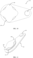
- the upper plate 140 is provided with a second hole 210 of smaller diameter with respect to the diameter of the hole 200, and positioned in proximity of the hole 200.
- the safety device 220 is provided with a lateral lower protuberance 260, spaced apart from the first 240 and second 250 protuberances.
- the first 240 and second 250 protuberances are formed with lower ribs 240', 250', of larger size than the respective protuberances.
- the lateral lower protuberance 260 is substantially cylindrical in shape, and ends with a third rib 260'.
- the first 240 protuberance with rib 240' are the closure means of hole 200, and the second protuberance 250 with rib 250' are a central retention means of the safety device.
- the lateral lower protuberance 260 with rib 260' forms a lateral retention means of the safety device.
- the term "lateral” designates a retention means that is not coaxial with the closure means but is located laterally with respect to the closure means and the central retention means.
- the function of the lateral retention means comprising protuberance 260 with rib 260' is of keeping the safety device fixed to the upper plate 140, when the pressure in the water collection chamber exceeds a predetermined value and also the central retention means is forced out of hole 200 by the water pressure.
- Operation of this first embodiment is similar as operation of the first example described above.
- the distance between the lower protuberances 240, 250 from the lateral protuberance 260 corresponds to the distance between the holes 200 and 210 of the plate 140, respectively.
- the safety device 220 is made of yielding and flexible plastic material, so as to allow insertion of the protuberance 260 into the hole 210 of the plate 140, exerting a pressure from above, so as to force the rib 260' to enter these holes.
- the diameter of the lateral protuberance 260 corresponds to the diameter of the hole 210, while the diameter of the rib 260' is slightly larger than that of the hole 210.
- the thickness of the rib 260' is greater than the thickness of the rib 250' of the second protuberance 240.
- the portion of the device corresponding to the lateral protuberance 260 with rib 260' is not risen from the hole 210 due to the greater resistance exerted by the third rib 260', namely, the lateral protuberance 260 with rib 260' remains tightly inserted in hole 210.
- the lateral retention means of the device prevents it from being thrown far from the shower head and being lost or accidentally ending up in the shower drain. In this way, an additional safety measure is provided in case of problems of the second rib 250' due to wear or possible manufacturing defects.
- Fig. 11 shows a variant of the first embodiment of the safety device, in which the only difference is that only two lobes 280' instead of four lobes are present in the rib 250' of the second protuberance 250.
- Figs. 12-15 show a safety device according to a second example of the shower head not falling under the scope of the appended claims.
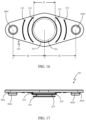
- the upper plate 140 of the shower head is provided with a couple of holes 210, 211, of smaller diameter with respect to the diameter of the hole 200, and positioned diametrically opposed in proximity of the hole 200, more particularly each placed at a distance D from the centre of hole 200.
- the safety device 320 is provided with a central protuberance 324 extending downwards, ending with a rib 324' ( Figs. 14-15 ). This part of the device is the closure means of hole 200.
- the safety device 320 is provided also with a couple of lateral protuberances 360a, 360b, disposed diametrically opposed to the central protuberance 324.
- Each lateral protuberance 360a, 360b is substantially cylindrical in shape and ends with a rib 360a', 360b'.
- Each lateral protuberance 360a, 360b with ribs 360a', 360b' is a retention means of the safety device 320.
- the distance of the lateral protuberances 360a, 360b from the central protuberance 324 is the same as the distance of the lateral holes 210, 211, from the hole 200 of the upper plate.
- the safety device 320 is mounted on the upper plate by inserting the central protuberance 324 in the hole 200 of the upper plate, and the lateral protuberances 360a, 360b in the holes 210, 211 of smaller diameter positioned diametrically opposed in proximity of the hole 200.
- the diameter of protuberance 324 has been designated as "d”, while distance between the centre of protuberance 324 from the centre of each of lateral protuberances 360a, 360b has been designated as D. According to an example, d ⁇ D ⁇ 2d.
- each lateral protuberance 360a, 360b is thus a lateral retention means of the safety device 320.
- the bottom side of safety device 320 is formed with a plurality of ribs 315 extending along portions of circumferences coaxial with the central protuberance 324. In the example illustrated in Figs. 14-16 four circumferential ribs 315 are present.
- Operation of this third embodiment is therefore similar as operation of the first embodiment described above, but with the retention means of keeping the device fixed to the shower head represented by the two lateral protuberances 360a, 360b, with ribs 360a', 360b'.
- the safety device 320 is made of yielding and flexible plastic material, so as to allow insertion of the protuberances 324, 360a, 360b into the respective holes of the upper plate, exerting a pressure from above, so as to force the ribs to enter these holes.
- the ribs 315 modify the adhesion of the device to the surface of the upper plate 140, thus allowing an easier removal of the safety device from the upper plate of the shower head, when necessary.
- the diameter of the lateral protuberances corresponds to the diameter of the respective holes, while the diameter of the ribs 360a', 360b' is slightly larger than that of the holes.
- the thickness of the ribs 360a',360b' is greater than the thickness of the rib 324' of the central protuberance 324.
- This construction provides an additional safety measure to avoid total ejection of the safety device from the shower head.
- the risen position of the closure while the safety device is retained to the shower head is the same as that shown in Fig. 21 , that is described below for the second embodiment of the invention.
- Figs. 17-21 show a safety device according to a second embodiment of the shower head according to the invention.
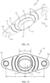
- This second embodiment is the same as the second example with the difference that the device 320 is provided with a second lower protuberance 325, substantially cylindrical in shape and coaxial to the first protuberance 324, and extending downwards from it.
- the second protuberance 325 ends with a second rib 325' of oval shape, having a size larger than the diameter of the first protuberance 324.
- the oval shape of rib 325' forms two lobed portions that extend in the longitudinal direction of the safety device 320.
- the lateral protuberances 360a, 360b and the ribs 315 on the bottom side of the safety device are the same as those of the second example.
- the distance of the lateral protuberances 360a, 360b from the central protuberance 324 is the same as defined for the second example, namely d ⁇ D ⁇ 2d.
- the device is provided also with a central retention means, as described for the first embodiment, variant with the rib 250' of oval shape, thus defining only two lobes.
- This embodiment thus comprises three retention means, one central and two lateral means.
- the functioning of the safety device of the second embodiment is essentially the same as that of the second example, and is shown in Figs. 20 and 21 .
- Fig. 20 shows the position of the device inserted in the holes of the upper plate 140 of the shower head.
- the lower protuberance 324 which has the same size as the central hole 200 of the upper plate 14, closes this hole.
- the first rib 324' abuts against the lower side of plate 140, ensuring a watertight closure.
- the lateral protuberances 360a, 360b are inserted into the lateral holes of plate 140, as described for the second example.
- Fig. 21 shows the functioning of the safety device when the pressure inside the water collection chamber exceeds the threshold value.
- the second rib 325' having an oval shape with two lobed portions 28, in the longitudinal direction has a larger diameter than the diameter of the hole 200 (feature not shown in Fig. 21 ). Therefore, the structure of the second rib 325' does not allow total ejection of the safety device 320 from the hole 200, but it allows passage of water thanks to the flanks narrower than the diameter of the central hole, as shown in Fig. 21 .
- This structure defines zones from which water can flow through hole 200 of the upper plate 14. This structure makes it possible the passage of water around the protuberance 325 when the safety device 320 when is in the risen position.
- the central retention means consists of the protuberance 325 with rib 325' of oval shape: it retains the device fixed to the plate 140 by the abutment of the lobes of the rib 325' against the bottom surface of the plate 140 (a disposition not shown in the figures).
- the lateral retention means consists of the protuberance 360a with rib 360a', and protuberance 360b with rib 360b', respectively.
- the improved shower head with the safety device according to the invention eliminates the problems caused by internal overpressure caused by clogging of the outlet holes as ejection of the valve clearly warns the user that numerous holes are clogged and that the shower head therefore requires cleaning and maintenance. This prevents a further increase of pressure from causing irreversible damage to the shower head.
- the safety valve can be reinserted into its seat, or can be replaced with a new valve, available as spare part at an affordable price.
- the improved shower head with the safety device according to the invention allows a gradual decrease in the pressure in case of its activation, preventing damage caused by sudden changes in pressure inside the water collection chamber.
- the improved shower head with the safety device according to the invention prevents this device from being lost or damaged due to its total ejection from the shower head.
Landscapes
- Health & Medical Sciences (AREA)
- Life Sciences & Earth Sciences (AREA)
- Engineering & Computer Science (AREA)
- Hydrology & Water Resources (AREA)
- Public Health (AREA)
- Water Supply & Treatment (AREA)
- Nozzles (AREA)
- Bathtubs, Showers, And Their Attachments (AREA)
- Paper (AREA)
- Sewing Machines And Sewing (AREA)
- Manufacturing Of Printed Wiring (AREA)
Claims (8)
- Pomme de douche comprenant une plaque inférieure (100) munie de trous de distribution d'eau (120) et une plaque supérieure (140) munie d'un trou d'arrivée d'eau (160), ladite plaque supérieure (140) étant fixée de manière étanche à ladite plaque inférieure (100) de manière à définir une chambre de collecte d'eau, ladite plaque supérieure (140) étant pourvue d'au moins un trou de sortie d'eau (200) dans lequel un dispositif de sécurité (220, 320) en matière plastique souple est logé de manière fonctionnelle, ledit dispositif de sécurité (220) étant muni d'un moyen de fermeture (240, 240') dudit trou de sortie d'eau (200) et d'au moins un moyen de retenue central (250, 250') conçu et calibré pour rester en prise avec ladite plaque supérieure (140) lorsque la pression dépasse un niveau maximum prédéterminé dans ladite chambre de collecte d'eau, selon laquelle ledit trou de sortie d'eau (200) est partiellement découvert et de l'eau est évacuée tandis que ledit moyen de retenue central reste en prise avec ladite plaque supérieure (140) ; ledit moyen de fermeture comprenant une première protubérance inférieure (240), de forme sensiblement cylindrique, se terminant par une première nervure (240') forcée de manière opérationnelle dans ledit trou (200), ladite première nervure (240') présentant une dimension plus grande que la dimension dudit trou (200) de ladite plaque supérieure (140), ledit moyen de retenue central comprenant une seconde protubérance (250) de forme sensiblement cylindrique et coaxiale à ladite première protubérance (240), se terminant par une seconde nervure (250') munie d'au moins deux parties à lobes (280, 280'), ladite seconde nervure (250') présentant une dimension supérieure à la dimension dudit trou (200) de ladite plaque supérieure (140) et une dimension supérieure à la dimension de ladite première nervure (240') ; dans lequel ladite plaque supérieure (140) comprend un trou supplémentaire (210) espacé dudit trou de sortie d'eau (200), et en ce que ledit dispositif de sécurité (220) comprend un moyen de retenue latéral comprenant une protubérance inférieure (260), de forme sensiblement cylindrique, se terminant par une nervure (260') forcée de manière opérationnelle dans ledit trou supplémentaire (210), ladite nervure (260') présentant une dimension supérieure à la dimension dudit trou supplémentaire (210) de ladite plaque supérieure (140).
- Pomme de douche selon la revendication 1, caractérisée en ce que lesdits trous (200, 210) sont positionnés à proximité l'un de l'autre.
- Pomme de douche selon la revendication 1, caractérisée en ce que ledit trou de sortie d'eau (200) présente une dimension supérieure audit trou supplémentaire (210).
- Pomme de douche selon l'une quelconque des revendications 1-3, caractérisée en ce que ladite seconde nervure (250') de ladite seconde protubérance (250) est pourvue de quatre parties à lobes (280).
- Pomme de douche selon une ou plusieurs des revendications précédentes, caractérisée en ce que ladite plaque supérieure est munie d'une paire de trous supplémentaires (210, 211) d'un diamètre plus petit par rapport audit trou de sortie d'eau (200), et positionnés de manière diamétralement opposée à proximité dudit trou de sortie d'eau (200), et en ce que ledit dispositif de sécurité (320) est pourvu d'un moyen de fermeture central (324, 324') et d'une paire de moyens de retenue latéraux comprenant des protubérances latérales (360a, 360b), disposés de manière diamétralement opposée audit moyen de fermeture central (324, 324'), chaque protubérance latérale (360a, 360b) étant de forme sensiblement cylindrique et se terminant par une nervure (360a', 360b).
- Pomme de douche selon la revendication 5, caractérisée en ce que lesdits trous (210, 211) de ladite plaque supérieure (140) et ladite paire de moyens de retenue latéraux (360a, 360a' ; 360b, 360b') sont espacés d'une distance (D) qui est définie par d ≤ D ≤ 2d, dans laquelle d est le diamètre de ladite première protubérance (324) dudit moyen de fermeture central.
- Pomme de douche selon une ou plusieurs des revendications précédentes, caractérisée en ce que ladite plaque supérieure (140) et ladite plaque inférieure (120) sont fixées l'une à l'autre de manière inamovible, ladite plaque supérieure (140) étant étirée et formée avec une concavité définissant un chambre de collecte d'eau.
- Pomme de douche selon la revendication 8, caractérisée en ce que ladite plaque supérieure (140) et ladite plaque inférieure (120) sont fixées de manière inamovible au moyen d'un soudage au laser.
Applications Claiming Priority (1)
| Application Number | Priority Date | Filing Date | Title |
|---|---|---|---|
| IT202018000003161U IT201800003161U1 (it) | 2018-08-01 | 2018-08-01 | Soffione per doccia perfezionato |
Publications (3)
| Publication Number | Publication Date |
|---|---|
| EP3603816A1 EP3603816A1 (fr) | 2020-02-05 |
| EP3603816B1 true EP3603816B1 (fr) | 2023-09-06 |
| EP3603816C0 EP3603816C0 (fr) | 2023-09-06 |
Family
ID=67543998
Family Applications (1)
| Application Number | Title | Priority Date | Filing Date |
|---|---|---|---|
| EP19188990.6A Active EP3603816B1 (fr) | 2018-08-01 | 2019-07-30 | Tête de douche améliorée |
Country Status (2)
| Country | Link |
|---|---|
| EP (1) | EP3603816B1 (fr) |
| IT (1) | IT201800003161U1 (fr) |
Families Citing this family (1)
| Publication number | Priority date | Publication date | Assignee | Title |
|---|---|---|---|---|
| IT202000006082A1 (it) | 2020-03-23 | 2021-09-23 | Zinox Laser S R L Con Socio Unico | Soffione per doccia con valvola di sicurezza perfezionata. |
Family Cites Families (10)
| Publication number | Priority date | Publication date | Assignee | Title |
|---|---|---|---|---|
| US2638263A (en) * | 1949-05-20 | 1953-05-12 | Duo Vent Vacuum Closure Compan | Flexible bag for vacuum sealing |
| US2769457A (en) * | 1953-06-01 | 1956-11-06 | Nat Presto Ind | Combined venting and overpressure release valve |
| AT252826B (de) * | 1965-06-23 | 1967-03-10 | Seidl Karl | Brausekopf, insbesondere von Hand- oder Schlauchbrausen, mit Überdrucksicherung |
| US3880187A (en) * | 1971-05-17 | 1975-04-29 | Crown Cork & Seal Co | Plug relief valve for pressure containers |
| US20050028271A1 (en) * | 2003-08-05 | 2005-02-10 | Sallick Robert J. | Vacuum relief valve for use in a shower head |
| CN202527296U (zh) * | 2012-04-06 | 2012-11-14 | 辉煌水暖集团有限公司 | 一种带自动泄压功能的花洒 |
| ITMI20131851A1 (it) * | 2013-11-07 | 2015-05-08 | Elettromeccanica Magistro Srl | Apparato per l'erogazione di acqua |
| CN104971834A (zh) * | 2015-06-30 | 2015-10-14 | 开平市汉顺洁具实业有限公司 | 一种防爆花洒 |
| US20170157626A1 (en) * | 2015-12-03 | 2017-06-08 | Sze Man Daphne CHAN | Anti-drip showerhead |
| DE102016213491A1 (de) * | 2016-07-22 | 2018-01-25 | Hansgrohe Se | Brausestrahlerzeugungsvorrichtung |
-
2018
- 2018-08-01 IT IT202018000003161U patent/IT201800003161U1/it unknown
-
2019
- 2019-07-30 EP EP19188990.6A patent/EP3603816B1/fr active Active
Also Published As
| Publication number | Publication date |
|---|---|
| IT201800003161U1 (it) | 2020-02-01 |
| EP3603816C0 (fr) | 2023-09-06 |
| EP3603816A1 (fr) | 2020-02-05 |
Similar Documents
| Publication | Publication Date | Title |
|---|---|---|
| US9839923B2 (en) | Showerhead | |
| EP3603816B1 (fr) | Tête de douche améliorée | |
| KR102119018B1 (ko) | 노즐+플러그형 오리피스조절용 스팀트랩 | |
| US10513841B1 (en) | Sink strainer assembly | |
| EP4421364A1 (fr) | Dispositif d'évacuation automatique de liquide | |
| US8302623B1 (en) | Anti-backflow insert for a fire hydrant outlet | |
| US7651613B2 (en) | Aircraft filter device with a member for keying and driving the cartridge | |
| JPH06306901A (ja) | 吐水口の整流板 | |
| US4394982A (en) | Liner plate for grinding mills | |
| EP2006212A1 (fr) | Fermeture | |
| AU3802200A (en) | Cartridge and device for treating liquids | |
| HK90294A (en) | Locking device for a pressure vessel | |
| CN216428472U (zh) | 喷嘴、马桶冲刷组件以及马桶 | |
| US10569113B2 (en) | Nozzle protection blow off cap | |
| EP2094133B1 (fr) | Machine à café expresso | |
| IT202100002744U1 (it) | Soffione per doccia migliorato | |
| US20220411253A1 (en) | Dispensing tap for rigid and flexible containers, preferably of the bag-in-box type | |
| IT202000006082A1 (it) | Soffione per doccia con valvola di sicurezza perfezionata. | |
| KR200455090Y1 (ko) | 뚜껑이 개봉된 상태에서 실링밴드의 빠짐이 방지되는 파우치 마개 | |
| CN201052078Y (zh) | 防爆压力锅 | |
| IT202100004733U1 (it) | Soffione per doccia migliorato. | |
| CN216304820U (zh) | 一种弹跳式下水器 | |
| CN204889623U (zh) | 壶盖及电热水壶 | |
| RU2806554C1 (ru) | Чашеобразное сопло выпуска душевых струй и душевая лейка | |
| EP2696730B1 (fr) | Ensemble d'infusion d'une machine permettant de produire une boisson et procédé de commande dudit ensemble d'infusion |
Legal Events
| Date | Code | Title | Description |
|---|---|---|---|
| PUAI | Public reference made under article 153(3) epc to a published international application that has entered the european phase |
Free format text: ORIGINAL CODE: 0009012 |
|
| STAA | Information on the status of an ep patent application or granted ep patent |
Free format text: STATUS: THE APPLICATION HAS BEEN PUBLISHED |
|
| AK | Designated contracting states |
Kind code of ref document: A1 Designated state(s): AL AT BE BG CH CY CZ DE DK EE ES FI FR GB GR HR HU IE IS IT LI LT LU LV MC MK MT NL NO PL PT RO RS SE SI SK SM TR |
|
| AX | Request for extension of the european patent |
Extension state: BA ME |
|
| STAA | Information on the status of an ep patent application or granted ep patent |
Free format text: STATUS: REQUEST FOR EXAMINATION WAS MADE |
|
| 17P | Request for examination filed |
Effective date: 20200728 |
|
| RBV | Designated contracting states (corrected) |
Designated state(s): AL AT BE BG CH CY CZ DE DK EE ES FI FR GB GR HR HU IE IS IT LI LT LU LV MC MK MT NL NO PL PT RO RS SE SI SK SM TR |
|
| STAA | Information on the status of an ep patent application or granted ep patent |
Free format text: STATUS: EXAMINATION IS IN PROGRESS |
|
| 17Q | First examination report despatched |
Effective date: 20210903 |
|
| GRAP | Despatch of communication of intention to grant a patent |
Free format text: ORIGINAL CODE: EPIDOSNIGR1 |
|
| STAA | Information on the status of an ep patent application or granted ep patent |
Free format text: STATUS: GRANT OF PATENT IS INTENDED |
|
| INTG | Intention to grant announced |
Effective date: 20230515 |
|
| GRAS | Grant fee paid |
Free format text: ORIGINAL CODE: EPIDOSNIGR3 |
|
| GRAA | (expected) grant |
Free format text: ORIGINAL CODE: 0009210 |
|
| STAA | Information on the status of an ep patent application or granted ep patent |
Free format text: STATUS: THE PATENT HAS BEEN GRANTED |
|
| AK | Designated contracting states |
Kind code of ref document: B1 Designated state(s): AL AT BE BG CH CY CZ DE DK EE ES FI FR GB GR HR HU IE IS IT LI LT LU LV MC MK MT NL NO PL PT RO RS SE SI SK SM TR |
|
| REG | Reference to a national code |
Ref country code: GB Ref legal event code: FG4D |
|
| REG | Reference to a national code |
Ref country code: CH Ref legal event code: EP |
|
| REG | Reference to a national code |
Ref country code: DE Ref legal event code: R096 Ref document number: 602019036621 Country of ref document: DE |
|
| REG | Reference to a national code |
Ref country code: IE Ref legal event code: FG4D |
|
| U01 | Request for unitary effect filed |
Effective date: 20231004 |
|
| U07 | Unitary effect registered |
Designated state(s): AT BE BG DE DK EE FI FR IT LT LU LV MT NL PT SE SI Effective date: 20231030 |
|
| PG25 | Lapsed in a contracting state [announced via postgrant information from national office to epo] |
Ref country code: GR Free format text: LAPSE BECAUSE OF FAILURE TO SUBMIT A TRANSLATION OF THE DESCRIPTION OR TO PAY THE FEE WITHIN THE PRESCRIBED TIME-LIMIT Effective date: 20231207 |
|
| PG25 | Lapsed in a contracting state [announced via postgrant information from national office to epo] |
Ref country code: RS Free format text: LAPSE BECAUSE OF FAILURE TO SUBMIT A TRANSLATION OF THE DESCRIPTION OR TO PAY THE FEE WITHIN THE PRESCRIBED TIME-LIMIT Effective date: 20230906 Ref country code: NO Free format text: LAPSE BECAUSE OF FAILURE TO SUBMIT A TRANSLATION OF THE DESCRIPTION OR TO PAY THE FEE WITHIN THE PRESCRIBED TIME-LIMIT Effective date: 20231206 Ref country code: HR Free format text: LAPSE BECAUSE OF FAILURE TO SUBMIT A TRANSLATION OF THE DESCRIPTION OR TO PAY THE FEE WITHIN THE PRESCRIBED TIME-LIMIT Effective date: 20230906 Ref country code: GR Free format text: LAPSE BECAUSE OF FAILURE TO SUBMIT A TRANSLATION OF THE DESCRIPTION OR TO PAY THE FEE WITHIN THE PRESCRIBED TIME-LIMIT Effective date: 20231207 |
|
| PG25 | Lapsed in a contracting state [announced via postgrant information from national office to epo] |
Ref country code: IS Free format text: LAPSE BECAUSE OF FAILURE TO SUBMIT A TRANSLATION OF THE DESCRIPTION OR TO PAY THE FEE WITHIN THE PRESCRIBED TIME-LIMIT Effective date: 20240106 |
|
| PG25 | Lapsed in a contracting state [announced via postgrant information from national office to epo] |
Ref country code: ES Free format text: LAPSE BECAUSE OF FAILURE TO SUBMIT A TRANSLATION OF THE DESCRIPTION OR TO PAY THE FEE WITHIN THE PRESCRIBED TIME-LIMIT Effective date: 20230906 |
|
| PG25 | Lapsed in a contracting state [announced via postgrant information from national office to epo] |
Ref country code: SM Free format text: LAPSE BECAUSE OF FAILURE TO SUBMIT A TRANSLATION OF THE DESCRIPTION OR TO PAY THE FEE WITHIN THE PRESCRIBED TIME-LIMIT Effective date: 20230906 Ref country code: RO Free format text: LAPSE BECAUSE OF FAILURE TO SUBMIT A TRANSLATION OF THE DESCRIPTION OR TO PAY THE FEE WITHIN THE PRESCRIBED TIME-LIMIT Effective date: 20230906 Ref country code: IS Free format text: LAPSE BECAUSE OF FAILURE TO SUBMIT A TRANSLATION OF THE DESCRIPTION OR TO PAY THE FEE WITHIN THE PRESCRIBED TIME-LIMIT Effective date: 20240106 Ref country code: ES Free format text: LAPSE BECAUSE OF FAILURE TO SUBMIT A TRANSLATION OF THE DESCRIPTION OR TO PAY THE FEE WITHIN THE PRESCRIBED TIME-LIMIT Effective date: 20230906 Ref country code: CZ Free format text: LAPSE BECAUSE OF FAILURE TO SUBMIT A TRANSLATION OF THE DESCRIPTION OR TO PAY THE FEE WITHIN THE PRESCRIBED TIME-LIMIT Effective date: 20230906 Ref country code: SK Free format text: LAPSE BECAUSE OF FAILURE TO SUBMIT A TRANSLATION OF THE DESCRIPTION OR TO PAY THE FEE WITHIN THE PRESCRIBED TIME-LIMIT Effective date: 20230906 |
|
| PG25 | Lapsed in a contracting state [announced via postgrant information from national office to epo] |
Ref country code: PL Free format text: LAPSE BECAUSE OF FAILURE TO SUBMIT A TRANSLATION OF THE DESCRIPTION OR TO PAY THE FEE WITHIN THE PRESCRIBED TIME-LIMIT Effective date: 20230906 |
|
| REG | Reference to a national code |
Ref country code: DE Ref legal event code: R097 Ref document number: 602019036621 Country of ref document: DE |
|
| PLBE | No opposition filed within time limit |
Free format text: ORIGINAL CODE: 0009261 |
|
| STAA | Information on the status of an ep patent application or granted ep patent |
Free format text: STATUS: NO OPPOSITION FILED WITHIN TIME LIMIT |
|
| 26N | No opposition filed |
Effective date: 20240607 |
|
| U20 | Renewal fee for the european patent with unitary effect paid |
Year of fee payment: 6 Effective date: 20240710 |
|
| PG25 | Lapsed in a contracting state [announced via postgrant information from national office to epo] |
Ref country code: MC Free format text: LAPSE BECAUSE OF FAILURE TO SUBMIT A TRANSLATION OF THE DESCRIPTION OR TO PAY THE FEE WITHIN THE PRESCRIBED TIME-LIMIT Effective date: 20230906 |
|
| REG | Reference to a national code |
Ref country code: CH Ref legal event code: PL |
|
| GBPC | Gb: european patent ceased through non-payment of renewal fee |
Effective date: 20240730 |
|
| PG25 | Lapsed in a contracting state [announced via postgrant information from national office to epo] |
Ref country code: CH Free format text: LAPSE BECAUSE OF NON-PAYMENT OF DUE FEES Effective date: 20240731 |
|
| PG25 | Lapsed in a contracting state [announced via postgrant information from national office to epo] |
Ref country code: GB Free format text: LAPSE BECAUSE OF NON-PAYMENT OF DUE FEES Effective date: 20240730 |
|
| PG25 | Lapsed in a contracting state [announced via postgrant information from national office to epo] |
Ref country code: IE Free format text: LAPSE BECAUSE OF NON-PAYMENT OF DUE FEES Effective date: 20240730 |
|
| U20 | Renewal fee for the european patent with unitary effect paid |
Year of fee payment: 7 Effective date: 20250714 |
|
| PG25 | Lapsed in a contracting state [announced via postgrant information from national office to epo] |
Ref country code: CY Free format text: LAPSE BECAUSE OF FAILURE TO SUBMIT A TRANSLATION OF THE DESCRIPTION OR TO PAY THE FEE WITHIN THE PRESCRIBED TIME-LIMIT; INVALID AB INITIO Effective date: 20190730 |
|
| PG25 | Lapsed in a contracting state [announced via postgrant information from national office to epo] |
Ref country code: HU Free format text: LAPSE BECAUSE OF FAILURE TO SUBMIT A TRANSLATION OF THE DESCRIPTION OR TO PAY THE FEE WITHIN THE PRESCRIBED TIME-LIMIT; INVALID AB INITIO Effective date: 20190730 |