EP3603973B1 - Farbkastenvorrichtung - Google Patents
Farbkastenvorrichtung Download PDFInfo
- Publication number
- EP3603973B1 EP3603973B1 EP18910598.4A EP18910598A EP3603973B1 EP 3603973 B1 EP3603973 B1 EP 3603973B1 EP 18910598 A EP18910598 A EP 18910598A EP 3603973 B1 EP3603973 B1 EP 3603973B1
- Authority
- EP
- European Patent Office
- Prior art keywords
- plate
- pair
- base
- ink fountain
- advancing
- Prior art date
- Legal status (The legal status is an assumption and is not a legal conclusion. Google has not performed a legal analysis and makes no representation as to the accuracy of the status listed.)
- Active
Links
Images



Classifications
-
- B—PERFORMING OPERATIONS; TRANSPORTING
- B41—PRINTING; LINING MACHINES; TYPEWRITERS; STAMPS
- B41F—PRINTING MACHINES OR PRESSES
- B41F31/00—Inking arrangements or devices
- B41F31/26—Construction of inking rollers
-
- B—PERFORMING OPERATIONS; TRANSPORTING
- B41—PRINTING; LINING MACHINES; TYPEWRITERS; STAMPS
- B41F—PRINTING MACHINES OR PRESSES
- B41F31/00—Inking arrangements or devices
- B41F31/02—Ducts, containers, supply or metering devices
- B41F31/04—Ducts, containers, supply or metering devices with duct-blades or like metering devices
- B41F31/05—Positioning devices therefor
-
- B—PERFORMING OPERATIONS; TRANSPORTING
- B41—PRINTING; LINING MACHINES; TYPEWRITERS; STAMPS
- B41F—PRINTING MACHINES OR PRESSES
- B41F31/00—Inking arrangements or devices
- B41F31/02—Ducts, containers, supply or metering devices
-
- B—PERFORMING OPERATIONS; TRANSPORTING
- B41—PRINTING; LINING MACHINES; TYPEWRITERS; STAMPS
- B41F—PRINTING MACHINES OR PRESSES
- B41F31/00—Inking arrangements or devices
- B41F31/02—Ducts, containers, supply or metering devices
- B41F31/04—Ducts, containers, supply or metering devices with duct-blades or like metering devices
Definitions
- the present invention relates to an ink fountain device to be used in printing presses.
- Ink fountain devices are installed in printing presses, such as offset printing presses and relief printing presses; they face ink fountain rollers in the presses to form ink fountains (reserves of ink) between them.
- An adjustable clearance between an ink fountain device and an ink fountain roller is meritorious; for example, if the clearance may temporarily be made wider during printing, then dust, such as paper dust, clogging the clearance may be removed.
- Patent Document 1 JP3194174B describes adjusting the clearance between an ink fountain device and an ink fountain roller by rotating the ink fountain device.
- Patent Document 2 JP4104764B2 ), which discloses an ink fountain device according to the preamble of claim 1.
- it is not easy to adjust the clearance accurately by this mechanism.
- Patent Document 1 JP3194174B and Patent Document 2: JP4104764B2 .
- the present inventor has investigated to compose an ink fountain device by a base and a slide plate on the base and to adjust the clearance between the ink fountain device and the ink fountain roller by moving the plate back and forth. If the friction between the base and the plate is sliding friction, a large output motor is necessary for moving the plate back and forth because of the large frictional resistance. However, members such as linear motion guides between the plate and the base make the advancing and retracting mechanism large and costly.
- the object of the invention is to reduce the friction between the base and the plate by a simple mechanism.
- An ink fountain device forms an ink fountain when facing an ink fountain roller of a printing press, comprises:
- the plate is supported by the balls over the base and therefore is advanced and retracted by a small force.
- a small size motor is enough for advancing and retracting the plate.
- the balls are retained within holes in the thin sheet, for example, with grease. Since a large number of the holes are provided, the plate is supported by a large number of the balls.
- the ink fountain device can be operated for a long period.
- a plurality of resilient members are provided for energizing the plate towards the base and are connected at their both ends to both the base and the plate.
- a resistance arises against the advancement and retraction of the plate.
- the energizing direction and the advancement and retraction direction are orthogonal, and the energizing force does not hinder the advancement and retraction of the plate.
- At least a bearing roller is provided on one of the base and the plate, and at least a recess accommodating the bearing roller is provided in the other of the base and the plate.
- the bearing roller is made in contact with the recess. Therefore, the plate does not shift along the direction perpendicular to the advancing and retracting direction over the clearance between the bearing roller and the recess.
- the bearing roller contacts the recess, the bearing roller is rotated without wearing. Therefore, the position of the plate along the direction perpendicular to the advancing and retracting direction is regulated for a long period.
- the advancing and retracting mechanism comprises: a pair of motors joined to the base; a pair of cams rotating with output shafts of the pair of motors and having circumferential surfaces constituting cam surfaces; a pair of rods in contact with the cam surfaces and advancing and retracting along the advancing and retracting direction according to the rotation of the motors; and a pair of connection members connecting the rods to the plate.
- the pair of the motors are rotated by the same angle, the pair of the rods advance and retract by the same distance, and the plate advances and retracts relative to the base by the same distance at two points.
- the cams allow the plate to advance and retract accurately with a small stroke.
- the advancing and retracting mechanism comprises: a pair of threaded holes provided on the plate; a pair of screws engaged with the pair of threaded holes; a pair of arms joined to the pair of screws; a rod connecting the pair of arms; a motor making one of the pair of arms rotate; and a pair of association members fixing axial positions of the pair of screws relative to the base.
- the plate, the pair of arms, and the rod constitute a quadratic link.
- a member is rotatably attached on the one of the pair of arms.
- One of the member and an output shaft of the motor is provided with a screw, and the other of the member and the output shaft of the motor is provided with a threaded hole such that the screw is engaged with the threaded hole.
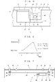
- Figs. 1 - 8 show an ink fountain device 2 according to an embodiment and a modification.
- the ink fountain device 2 faces an ink fountain roller 32; the ink reserved between them forms an ink fountain.
- the ink fountain device 2 is provided with a base 4 and a plate 6; the base 4 is joined to a printing press, such as an offset printing press, or a relief printing press.
- the plate 6 is supported by the base 4 and advances towards the ink fountain roller 32 and retracts from the roller 32.
- a thin sheet 8 is provided between the base 4 and the plate 6. As enlargedly shown in a left upper portion in Fig. 1 , the thin sheet 8 is provided with a large number of holes 10; the holes 10 retain balls 12 and grease not shown, and a large number of the balls 12 support the plate 6.
- the holes 10 are penetrating holes, but they may be holes having bottoms.
- a slight gap is made between the upper surface of the thin sheet 8 and the bottom face of the plate 6 so that the plate 6 is supported by the base 4 and may slide.
- the thin sheet 8 is, for example, a thin steel plate, the balls 12 are, for example, steel balls, but the materials for them are arbitrary.
- the thin sheet 8 retains a large number of the balls 12, and, since the thin sheet 8 is slightly thinner than the diameter of the balls 12, the thin sheet 8 and the plate 6 are not in contact. Further, the diameter of the holes 10 are larger than the diameter of the balls 12, the ball 12 rotates and moves within the hole 10, and the hole 10 retains grease with the ball 12.
- a plurality of resilient members 14 energize the plate 6 towards the base 4 so that the bottom face of the plate 6 is made in close contact with the balls 12 and that the gap between the base 4 and the plate 6 is made narrower. This prevents the ink, paper dust, liquid cleaners for the plate 6 from entering into the gap between the plate 6 and the thin sheet 8.
- the resilient members 14 are, for example, tensile springs and the species of the resilient members are arbitrary. Hooks 16, 18 support the two ends of the resilient members 14; the base portions of the hooks 16 are screwed on the plate 6, and the base portions of the hooks 18 are accommodated within recesses 19 and screwed on the base 4.
- the resilient members 14 make the plate 6 elastically energized towards the base 4 and a plurality of the members are provided between the plate 6 and the base 4 so as to make them in close contact over the entire surface.
- Indicated by 20 is a bearing roller; the base portion of it is screwed on the base 4, and the roller part 21 at the tip end is accommodated in a recess 22 of the plate 6.
- the roller part 21 contacts on a sidewall of the recess 22.
- the lateral position of the plate 6 relative to the base 4 is regulated.
- the base portion of the bearing roller 20 may be fixed to the plate 6, and the roller part 21 and the recess 22 may be provided towards and in the base 4. Since the wear is negligible when the bearing roller 20 is made in contact with the recess 22, the bearing roller 20 may regulate the lateral position of the plate 6 during the service life of the ink fountain device 2 without the exchange of the roller 20.
- L-shaped pieces 30, for example, a left and right pair of them, are joined to the base 4, and compressed springs 31 are provided between the L-shaped pieces and the plate 6 so that the plate 6 is energized towards the ink fountain roller 32 at the left side in Fig. 1 .
- the left and right direction (the lateral direction) is the lengthwise direction of the base 4 and the plate 6.
- an L-shaped piece 33 is provided along the underside of the tip end of the plate 6 towards the ink fountain roller 32 to prevent, for example, ink from intruding.
- the L-shaped piece 33 may not be provided.
- the exterior surface of the plate 6 may be covered by a plastic film 34 shown by a chain line in Fig. 1 so that the ink does not contact the plate 6.
- Fig. 2 indicates the thin sheet 8 on the base 4, and the bottom surface of the plate 6 is stacked over the sheet.
- the holes 10 are arranged on the surface of the thin sheet 8, and each hole 10 retains a ball 12.
- Indicated by 35 are holes for inserting screws to fix the thin sheet 8 on the base 4 by the screws. Even if the thin sheet 8 is not fixed to the base 4, the thin sheet 8 does not move and does not extend beyond the base 4. Therefore, the thin sheet 8 may not be fixed to the base 4.
- the threaded portions of the hooks 16 are inserted in holes 36 of the thin sheet 8, and the threaded portion of the bearing roller 20 is inserted in a hole 38.
- the advancing and retracting mechanisms 28 are accommodated so that the plate 6 is made advancing and retracting towards and from the ink fountain roller 32.
- the movement towards the ink fountain roller 32 is called advancement and the movement from the roller 32 is called retraction.
- Fig. 3 shows the bottom of the plate 6.
- the recess 22 is provided, for example, at one portion in or near the center portion along the lengthwise direction and accommodates the roller part 21 of the bearing roller 20.
- indicated by 24 is a bearing.
- the recess 22 is, for example, rectangular and its lengthwise direction is parallel to the up-down direction in Fig. 3 .
- the position of the plate 6 is regulated along the left and right direction of the plate 6 (the lengthwise direction of the ink fountain device 2).
- the base portions of the hooks 16 are screwed on threaded holes 26.
- Figs. 4 to 6 show the advancing and retracting mechanism 28 for the plate 6.
- Indicated by 41 is a servo-motor; it may be a simpler motor such as a pulse motor.
- the servo-motor 41 has a driving shaft 42 on which an eccentric cam 43 is fixed.
- the cam 43 is, for example, circular, and the center of the cam 43 and the center of the driving shaft 42 is slightly shifted. This shift makes the plate 6 advance and retract; the circumferential surface of the cam 43 constitutes the cam surface.
- One end of a rod 44 is kept in contact with the cam surface, and the other end of the rod 44 is kept in contact with an adjustment screw 45.
- the adjustment screw 45 is screwed on an attachment plate 47, the plate 47 is fixed to the plate 6 by a couple of knock pins 48.
- the cam 43 is accommodated within a casing 46 and is freely rotatable, and the attachment method of the plate 47 to the plate 6 is arbitrary.
- One of the left and right pair of the advancing and retracting mechanisms 28, 28 may not be provided with the servo-motor 41.
- only one of the left and right advancing and retracting mechanisms may be provided with the servo-motor 41, and the cam 43 in the other advancing and retracting mechanism may be driven by a shaft extending between the left and right recesses 40, 40.
- the function of the advancing and retracting mechanism 28 will be described.
- the relation between the phase of the cam 43 and the advancing and retracting quantity of the plate 6 (the change in the distance between the cam surface and central axis of the cam) is indicated in Fig. 6 .
- the horizontal axis indicates the phase of the cam 43 and the vertical axis indicates the tip end position of the plate 6.
- the chain lines indicate the three positions of the tip end of the plate; at the most advancing "halting" the tip end of the plate 6 is in close contact with the ink fountain roller 32 so as to prevent the ink from leaking. This position is provided to prevent the ink from leaking when the printing press is halted with the ink being reserved in the ink fountain, but this position may not be provided.
- the clearance between the tip end of the plate 6 and the ink fountain roller 32 is one suitable for the printing. Dust such as paper dust is removed at the "cleaning" position where the tip end of the plate 6 is retracted and the dust clogged between the ink fountain roller 32 and the plate 6 is removed.
- the cam 43 rotates between these three positions.
- the plate 6 Since the plate 6 is energized towards the advancing direction by the compressed spring 31, the one end of the rod 44 is always in contact with the cam surface of the cam 43, and the other end is always in contact with the adjustment screw 45.
- the cam 43 is rotated by the servo-motor 41, the rod 44 advances and retracts, and therefore, the attachment plate 47 advances and retracts via the adjustment screw 45.
- the plate 6 Since the plate 6 is fixed to the plate 47 via the knock pins 48, the plate 6 advances and retracts according to the rotation of the cam 43. In this way, the plate 6 advances and retracts accurately with a small stroke by the servo-motor 41, the eccentric cam 43, and the rod 44 connected to the plate 6.
- Figs. 7 and 8 indicate a modification of the advancing and retracting mechanism having the following features in common with the embodiment:
- connection members 52 are fixed to the plate 6 by screws 72 shown in Fig. 8 .
- the plate 6 has threaded holes 74 which are engaged with the screws 72.
- association members 54 fixed to the base 4' support the shanks of the screws 72.
- the association members 54 comprise ring-like members supporting the shanks of the screws 72 or shafts of the connection members 52.
- the connection members 52 are rotatable with the screws 72 relative to the association members 54, and the axial positions of the screws 72 are fixed.
- an arm 56 is fixed to one of the connection members 52 and another arm 58 is fixed to the other of the connection members 52.
- the two ends of a rod 60 that is parallel to the lengthwise direction of the base 4' are connected to the arms 56, 58 by pins 62, 62 so that the rod is allowed to rotate around the pins.
- a pin 65 is connected to the arm 56 rotatably and it has an integral threaded portion 66; the threaded portion is screwed on a threaded hole on the shaft 64 of the servo-motor 50.
- the opposite end of the servo-motor 50 to the shaft 64 is connected to a bracket 68 fixed to the base 4' by a pin 70 so that the servo-motor is allowed to rotate around the pin.
- Figs. 7 and 8 The function of the advancing and retracting mechanism in Figs. 7 and 8 will be described.
- the threaded portion 66 moves laterally so that the arm 56 rotates with the connection member 52.
- the lateral direction means the left and right direction in Fig. 7 . Since the plate 6, the arms 56, 58, and the rod 60 constitute a quadratic link, the arm 58 rotates with the arm 56 towards the same direction by the same angle. As a result, the pair of connection members 52, 52 rotate by the same angle.
- the base portions of the screws 72 are fixed to the connection members 52, and the shanks of the screws 72 are supported by the association members 54. Therefore, when the connection members 52 rotate, the screws 72 also rotate, and the plate 6 advances and retracts relative to the base 4'.
- the advancement and the retraction refer to motions along the lateral direction in Fig. 8 . Since the arms 56, 58 rotate by the same angle, the plate 6 advances and retracts at its left and right positions by the same distance.
- the functions of the embodiment and the modification will be described.
- the advancing and retracting mechanisms 28 in Figs. 4 and 5 or the advancing and retracting mechanism in Figs. 7 and 8 make the plate 6 advance and retract; therefore, the clearance between the tip end of the plate 6 and the ink fountain roller 32 is accurately adjusted with a small stroke.
- the clearance between the tip end of the plate 6 and the ink fountain roller 32 when the clearance between the tip end of the plate 6 and the ink fountain roller 32 can accurately be adjusted, the clearance is temporarily enlarged during printing so that the clogging dust to the clearance such as paper dust may be removed and after that the clearance may be returned to the previous value.
- a blade not shown is made in contact with the ink fountain roller 32 so that the dust such as paper dust is removed with ink. After the removal of the paper dust the clearance between the tip end of the plate 6 and the ink fountain roller 32 is returned to the previous value.
- the time duration for enlarging the clearance is, for example, shorter than the rotational period of the ink fountain roller 32. During the time duration, the ink supply to the ductor roller not shown at the downstream of the roller 32 is stopped. Therefore, it is preferable to increase the contact time temporarily between the ductor roller and the ink fountain roller 32 so as to prevent the fluctuations of the printing density due to the removal of the paper dust.
- the advancing retracting mechanisms in Figs. 4 to 8 are provided for this purpose. Further, the advancing and retracting mechanisms can be used to control the ink supply quantity according to the species of the ink and desired printing densities.
- the resistance against the advancement and retraction of the plate 6 is made small by a large number of the balls 12 supporting the plate 6 and by the resilient members 14 energizing the plate 6 towards the base 4, 4'. In this way, the small output motors 41, 50 are made to advance and retract the plate accurately.
- the plate 6 is regulated in its advancing and retracting position at the left and right two points. Therefore, the plate 6 does not tilt relative to the base 4, 4'. However, the plate 6 may shift along the longitudinal direction (left and right direction) of the base 4, 4'. Accordingly, the bearing roller 20 and the recess 22 shown in Figs. 1 and 3 regulate the left and right position of the plate 6. Besides, if the bearing roller 20 is made in contact with the sidewalls of the recess 22, the wear of the bearing roller and the recess is very slight.
Landscapes
- Inking, Control Or Cleaning Of Printing Machines (AREA)
- Ink Jet (AREA)
Claims (5)
- Farbkastenvorrichtung (2) zum Bilden eines Farbkastens, wenn sie einem Farbduktor (32) einer Druckmaschine gegenübersteht, umfassend:eine Basis (4, 4'); eine Platte (6); einen Aus- und Einfahrmechanismus (28) zum Aus- und Einfahren der Platte (6) entlang einer Aus- und Einfahrrichtung zu und von dem Duktor (32);dadurch gekennzeichnet, dass ein dünnes Blech (8) auf der Basis (4, 4') angeordnet ist,wobei das dünne Blech (8) mehrere Löcher (10) aufweist, die drehbar Kügelchen (12) aufnehmen, und das eine geringere Dicke als ein Durchmesser der Kügelchen (12) aufweist,und wobei die Platte (6) über dem dünnen Blech (8) angeordnet und von den Kügelchen (12) getragen wird.
- Farbkastenvorrichtung (2) nach Anspruch 1 ferner umfassend eine Vielzahl von federnden Elementen (14), welche die Platte (6) in Richtung auf die Basis (4, 4') aktivieren und an ihren beiden Enden mit der Basis (4, 4') und der Platte (6) verbunden sind.
- Farbkastenvorrichtung (2) nach Anspruch 1 oder 2, wobei mindestens eine Lagerrolle (20) auf einer von der Basis (4, 4') und der Platte (6) bereitgestellt wird, und mindestens eine Vertiefung (22), welche die Lagerrolle (20) aufnimmt, auf der anderen von der Basis (4, 4') und der Platte (6) bereitgestellt wird, so dass die Lagerrolle (20) die Vertiefung (22) kontaktiert, wenn auf die Platte (6) gedrückt wird, damit sie sich über einen zulässigen Bereich hinaus entlang einer Richtung, die zur Aus- und Einfahrrichtung rechtwinklig steht, verschiebt.
- Farbkastenvorrichtung (2) nach einem der Ansprüche 1 bis 3, wobei der Aus- und Einfahrmechanismus (28) umfasst: ein Paar von Motoren (41), die mit der Basis (4) zusammengefügt sind; ein Paar von Nocken (43), die sich mit den Abtriebswellen (42) des Paars von Motoren (41) drehen und Umfangsflächen aufweisen, die Nockenflächen bilden; ein Paar von Stäben (44) in Kontakt mit den Nockenflächen, und die entlang der Aus- und Einfahrrichtung gemäß der Drehung der Motoren (41) aus- und einfahren; und ein Paar von Verbindungselementen (45, 47, 48), welche die Stäbe (44) mit der Platte (6) verbinden, so dass die Platte (6) im Verhältnis zur Basis (4) um den gleichen Abstand an zwei Stellen aus- und einfährt.
- Farbkastenvorrichtung (2) nach einem der Ansprüche 1 bis 3, wobei der Aus- und Einfahrmechanismus (28) umfasst: ein Paar von Gewindelöchern (74), die auf der Platte (6) bereitgestellt werden; ein Paar von Schrauben (72), die mit dem Paar von Gewindelöchern (74) in Eingriff gebracht werden; ein Paar von Armen (56, 58), die mit dem Paar von Schrauben (72) zusammengefügt sind; einen Stab (60), der das Paar von Armen (56, 58) verbindet; einen Motor (50), der einen von dem Paar von Armen (56, 58) in Drehung versetzt; und ein Paar von Zuordnungselementen (54), welche die axialen Positionen des Paars von Schrauben (72) im Verhältnis zur Basis (4') festlegen,
wobei die Platte (6), das Paar von Armen (56, 58) und der Stab (60) ein quadratisches Verbindungsglied bilden, und wobei ein Element (65) an dem einem von dem Paar von Armen (56, 58) drehbar angebracht ist, eines von dem Element (65) und einer Abtriebswelle (64) des Motors (50) mit einer Schraube (66) versehen ist, und ein anderes von dem Element (65) und der Abtriebswelle (64) des Motors (50) mit einem Gewindeloch versehen ist, so dass die Schraube (66) mit dem Gewindeloch in Eingriff steht.
Applications Claiming Priority (2)
| Application Number | Priority Date | Filing Date | Title |
|---|---|---|---|
| JP2018054119 | 2018-03-22 | ||
| PCT/JP2018/046733 WO2019181115A1 (ja) | 2018-03-22 | 2018-12-19 | インキ壺装置 |
Publications (3)
| Publication Number | Publication Date |
|---|---|
| EP3603973A1 EP3603973A1 (de) | 2020-02-05 |
| EP3603973A4 EP3603973A4 (de) | 2021-01-13 |
| EP3603973B1 true EP3603973B1 (de) | 2022-11-09 |
Family
ID=67986151
Family Applications (1)
| Application Number | Title | Priority Date | Filing Date |
|---|---|---|---|
| EP18910598.4A Active EP3603973B1 (de) | 2018-03-22 | 2018-12-19 | Farbkastenvorrichtung |
Country Status (11)
| Country | Link |
|---|---|
| US (1) | US11235567B2 (de) |
| EP (1) | EP3603973B1 (de) |
| JP (1) | JP6844886B2 (de) |
| KR (1) | KR102190191B1 (de) |
| CN (1) | CN110582405A (de) |
| ES (1) | ES2934318T3 (de) |
| MX (1) | MX2020009816A (de) |
| MY (1) | MY203510A (de) |
| RU (1) | RU2741478C1 (de) |
| TW (1) | TWI704060B (de) |
| WO (1) | WO2019181115A1 (de) |
Families Citing this family (1)
| Publication number | Priority date | Publication date | Assignee | Title |
|---|---|---|---|---|
| JP2023554605A (ja) * | 2020-12-17 | 2023-12-28 | エクシス プリプレス エヌ.ブイ. | 版を操作するための装置および方法 |
Family Cites Families (19)
| Publication number | Priority date | Publication date | Assignee | Title |
|---|---|---|---|---|
| US2949992A (en) * | 1955-02-07 | 1960-08-23 | William J Weinberg | Anti-friction ball transfer |
| DE2951653C2 (de) * | 1979-12-21 | 1983-04-14 | M.A.N.- Roland Druckmaschinen AG, 6050 Offenbach | Vorrichtung zum Dosieren von Farbe auf der Farbkastenwalze eines Farbwerks für Druckmaschinen |
| DE3311113C1 (de) * | 1983-03-26 | 1988-05-05 | M.A.N.- Roland Druckmaschinen AG, 6050 Offenbach | Dosierelemente in Farbkaesten von Offsetdruckmaschinen |
| JP2576597Y2 (ja) * | 1991-06-03 | 1998-07-16 | ジェーピーイー株式会社 | 印刷機のインク壺装置 |
| JP3194174B2 (ja) * | 1993-09-10 | 2001-07-30 | アイマー・プランニング株式会社 | 印刷機のインキ供給装置 |
| FR2778365B1 (fr) * | 1998-05-11 | 2000-12-15 | Jean Claude Sarda | Perfectionnements apportes aux encriers des presses a imprimer et a leur mode de nettoyage |
| JP2964246B1 (ja) * | 1998-07-27 | 1999-10-18 | 株式会社東京機械製作所 | キーレス印刷機のインキ貯留装置 |
| JP3189893B2 (ja) * | 1998-09-08 | 2001-07-16 | 株式会社東京機械製作所 | インキ壺装置におけるインキ出し隙間調整装置 |
| JP4104764B2 (ja) * | 1999-02-16 | 2008-06-18 | ジェーピーイー株式会社 | 印刷機のインキ壺装置 |
| DE10058607B4 (de) * | 2000-11-25 | 2004-12-30 | Koenig & Bauer Ag | Farbdosiereinrichtung am Farbkasten von Druckmaschinen |
| TW522924U (en) * | 2002-05-14 | 2003-03-01 | Shun-Shiu Su | Automatic roller printing machine |
| TWM275095U (en) * | 2004-12-31 | 2005-09-11 | Guann Way Technologies Co Ltd | Ink tank structure for roller of lithographic plate printing machine |
| DE102007025166A1 (de) * | 2007-05-29 | 2009-01-22 | Kba-Metronic Ag | Steuerbare Rakelmesser |
| DE102007042378A1 (de) * | 2007-09-06 | 2009-03-12 | Koenig & Bauer Aktiengesellschaft | Farbkasten für Druckmaschinen |
| TW200952597A (en) * | 2008-06-13 | 2009-12-16 | Fih Hong Kong Ltd | Sliding cover structure |
| JP2010030265A (ja) * | 2008-06-24 | 2010-02-12 | Suhara Kk | 印刷機におけるインキつぼ装置 |
| JP3194174U (ja) | 2014-08-29 | 2014-11-06 | 信代 樋口 | 雨のしずく傘カバー付き一体型長傘 |
| CN106113936B (zh) * | 2016-08-02 | 2018-09-28 | 昆明理工大学 | 一种印刷机智能供墨装置及供墨方法 |
| CN206299262U (zh) * | 2016-11-01 | 2017-07-04 | 天津市腾泰建材有限公司 | 一种推拉门窗滑道滚动装置 |
-
2018
- 2018-12-19 EP EP18910598.4A patent/EP3603973B1/de active Active
- 2018-12-19 RU RU2020131980A patent/RU2741478C1/ru active
- 2018-12-19 ES ES18910598T patent/ES2934318T3/es active Active
- 2018-12-19 CN CN201880028670.0A patent/CN110582405A/zh active Pending
- 2018-12-19 JP JP2020507356A patent/JP6844886B2/ja active Active
- 2018-12-19 US US16/609,056 patent/US11235567B2/en active Active
- 2018-12-19 MY MYPI2020004438A patent/MY203510A/en unknown
- 2018-12-19 WO PCT/JP2018/046733 patent/WO2019181115A1/ja not_active Ceased
- 2018-12-19 MX MX2020009816A patent/MX2020009816A/es unknown
- 2018-12-19 KR KR1020197031146A patent/KR102190191B1/ko active Active
-
2019
- 2019-03-21 TW TW108109687A patent/TWI704060B/zh not_active IP Right Cessation
Also Published As
| Publication number | Publication date |
|---|---|
| US20200147955A1 (en) | 2020-05-14 |
| KR102190191B1 (ko) | 2020-12-14 |
| JPWO2019181115A1 (ja) | 2020-06-18 |
| RU2741478C1 (ru) | 2021-01-26 |
| JP6844886B2 (ja) | 2021-03-17 |
| KR20190133202A (ko) | 2019-12-02 |
| TW201940351A (zh) | 2019-10-16 |
| MX2020009816A (es) | 2020-10-14 |
| US11235567B2 (en) | 2022-02-01 |
| WO2019181115A1 (ja) | 2019-09-26 |
| MY203510A (en) | 2024-06-30 |
| CN110582405A (zh) | 2019-12-17 |
| ES2934318T3 (es) | 2023-02-21 |
| EP3603973A1 (de) | 2020-02-05 |
| TWI704060B (zh) | 2020-09-11 |
| BR112020016749A2 (pt) | 2020-12-15 |
| EP3603973A4 (de) | 2021-01-13 |
Similar Documents
| Publication | Publication Date | Title |
|---|---|---|
| EP3141345B1 (de) | Modulare und einstellbare gleitbasis | |
| US4151797A (en) | Doctor blade apparatus | |
| JPS6038160A (ja) | 書籍印刷並びにオフセツト印刷機用のインキ調量装置 | |
| US11235567B2 (en) | Ink fountain device | |
| US3498164A (en) | Adjustable tool support | |
| KR102165946B1 (ko) | 잉크 리저버의 청소 장치, 인쇄기 및 잉크 리저버의 청소 방법 | |
| US4372207A (en) | Ink fountain devices for use in printing press | |
| US5505131A (en) | Ink fountain apparatus | |
| US4655133A (en) | Ink fountain assembly and segmented film metering, blade | |
| US7032511B2 (en) | Fountain ink feed system | |
| EP0180134B1 (de) | Farbkasten und geteiltes Farbmesser | |
| EP2844471B1 (de) | Farbwerk mit einstellung von walzen durch biegeplatte und verfahren zur einstellung | |
| JP2017019221A (ja) | ファニッシャロールを備えた輪転印刷機 | |
| CN210501911U (zh) | 可微调结构及打印机 | |
| US4802411A (en) | Adjustable mounting bracket for printing or duplicating machine | |
| JP3755578B2 (ja) | 平行度調整装置、および記録装置 | |
| JP6488141B2 (ja) | 印刷機の湿水装置 | |
| KR0165835B1 (ko) | 프레스용 에어 롤 피더장치 | |
| JPH04259553A (ja) | ドクター装置 | |
| US20230133937A1 (en) | Printing system | |
| BR112020016749B1 (pt) | Dispositivo de fonte de tinta | |
| JP2003231240A (ja) | インキつぼのブレード調整装置 | |
| JP2007106052A (ja) | インキつぼ | |
| JP2003011329A (ja) | 印刷機におけるインキつぼのブレード調整装置 | |
| JPH1142766A (ja) | インキつぼ |
Legal Events
| Date | Code | Title | Description |
|---|---|---|---|
| STAA | Information on the status of an ep patent application or granted ep patent |
Free format text: STATUS: THE INTERNATIONAL PUBLICATION HAS BEEN MADE |
|
| PUAI | Public reference made under article 153(3) epc to a published international application that has entered the european phase |
Free format text: ORIGINAL CODE: 0009012 |
|
| STAA | Information on the status of an ep patent application or granted ep patent |
Free format text: STATUS: REQUEST FOR EXAMINATION WAS MADE |
|
| 17P | Request for examination filed |
Effective date: 20191023 |
|
| AK | Designated contracting states |
Kind code of ref document: A1 Designated state(s): AL AT BE BG CH CY CZ DE DK EE ES FI FR GB GR HR HU IE IS IT LI LT LU LV MC MK MT NL NO PL PT RO RS SE SI SK SM TR |
|
| AX | Request for extension of the european patent |
Extension state: BA ME |
|
| RIN1 | Information on inventor provided before grant (corrected) |
Inventor name: IZUME, MASAYUKI |
|
| A4 | Supplementary search report drawn up and despatched |
Effective date: 20201210 |
|
| RIC1 | Information provided on ipc code assigned before grant |
Ipc: B41F 31/02 20060101ALI20201204BHEP Ipc: B41F 31/05 20060101ALI20201204BHEP Ipc: B41F 31/04 20060101AFI20201204BHEP |
|
| DAV | Request for validation of the european patent (deleted) | ||
| DAX | Request for extension of the european patent (deleted) | ||
| GRAP | Despatch of communication of intention to grant a patent |
Free format text: ORIGINAL CODE: EPIDOSNIGR1 |
|
| STAA | Information on the status of an ep patent application or granted ep patent |
Free format text: STATUS: GRANT OF PATENT IS INTENDED |
|
| INTG | Intention to grant announced |
Effective date: 20220729 |
|
| GRAS | Grant fee paid |
Free format text: ORIGINAL CODE: EPIDOSNIGR3 |
|
| GRAA | (expected) grant |
Free format text: ORIGINAL CODE: 0009210 |
|
| STAA | Information on the status of an ep patent application or granted ep patent |
Free format text: STATUS: THE PATENT HAS BEEN GRANTED |
|
| AK | Designated contracting states |
Kind code of ref document: B1 Designated state(s): AL AT BE BG CH CY CZ DE DK EE ES FI FR GB GR HR HU IE IS IT LI LT LU LV MC MK MT NL NO PL PT RO RS SE SI SK SM TR |
|
| REG | Reference to a national code |
Ref country code: GB Ref legal event code: FG4D |
|
| REG | Reference to a national code |
Ref country code: CH Ref legal event code: EP Ref country code: AT Ref legal event code: REF Ref document number: 1530096 Country of ref document: AT Kind code of ref document: T Effective date: 20221115 |
|
| REG | Reference to a national code |
Ref country code: DE Ref legal event code: R096 Ref document number: 602018043009 Country of ref document: DE |
|
| REG | Reference to a national code |
Ref country code: IE Ref legal event code: FG4D |
|
| REG | Reference to a national code |
Ref country code: NL Ref legal event code: FP |
|
| REG | Reference to a national code |
Ref country code: ES Ref legal event code: FG2A Ref document number: 2934318 Country of ref document: ES Kind code of ref document: T3 Effective date: 20230221 |
|
| REG | Reference to a national code |
Ref country code: LT Ref legal event code: MG9D |
|
| REG | Reference to a national code |
Ref country code: AT Ref legal event code: MK05 Ref document number: 1530096 Country of ref document: AT Kind code of ref document: T Effective date: 20221109 |
|
| PG25 | Lapsed in a contracting state [announced via postgrant information from national office to epo] |
Ref country code: SE Free format text: LAPSE BECAUSE OF FAILURE TO SUBMIT A TRANSLATION OF THE DESCRIPTION OR TO PAY THE FEE WITHIN THE PRESCRIBED TIME-LIMIT Effective date: 20221109 Ref country code: PT Free format text: LAPSE BECAUSE OF FAILURE TO SUBMIT A TRANSLATION OF THE DESCRIPTION OR TO PAY THE FEE WITHIN THE PRESCRIBED TIME-LIMIT Effective date: 20230309 Ref country code: NO Free format text: LAPSE BECAUSE OF FAILURE TO SUBMIT A TRANSLATION OF THE DESCRIPTION OR TO PAY THE FEE WITHIN THE PRESCRIBED TIME-LIMIT Effective date: 20230209 Ref country code: LT Free format text: LAPSE BECAUSE OF FAILURE TO SUBMIT A TRANSLATION OF THE DESCRIPTION OR TO PAY THE FEE WITHIN THE PRESCRIBED TIME-LIMIT Effective date: 20221109 Ref country code: FI Free format text: LAPSE BECAUSE OF FAILURE TO SUBMIT A TRANSLATION OF THE DESCRIPTION OR TO PAY THE FEE WITHIN THE PRESCRIBED TIME-LIMIT Effective date: 20221109 Ref country code: AT Free format text: LAPSE BECAUSE OF FAILURE TO SUBMIT A TRANSLATION OF THE DESCRIPTION OR TO PAY THE FEE WITHIN THE PRESCRIBED TIME-LIMIT Effective date: 20221109 |
|
| PG25 | Lapsed in a contracting state [announced via postgrant information from national office to epo] |
Ref country code: RS Free format text: LAPSE BECAUSE OF FAILURE TO SUBMIT A TRANSLATION OF THE DESCRIPTION OR TO PAY THE FEE WITHIN THE PRESCRIBED TIME-LIMIT Effective date: 20221109 Ref country code: PL Free format text: LAPSE BECAUSE OF FAILURE TO SUBMIT A TRANSLATION OF THE DESCRIPTION OR TO PAY THE FEE WITHIN THE PRESCRIBED TIME-LIMIT Effective date: 20221109 Ref country code: LV Free format text: LAPSE BECAUSE OF FAILURE TO SUBMIT A TRANSLATION OF THE DESCRIPTION OR TO PAY THE FEE WITHIN THE PRESCRIBED TIME-LIMIT Effective date: 20221109 Ref country code: IS Free format text: LAPSE BECAUSE OF FAILURE TO SUBMIT A TRANSLATION OF THE DESCRIPTION OR TO PAY THE FEE WITHIN THE PRESCRIBED TIME-LIMIT Effective date: 20230309 Ref country code: HR Free format text: LAPSE BECAUSE OF FAILURE TO SUBMIT A TRANSLATION OF THE DESCRIPTION OR TO PAY THE FEE WITHIN THE PRESCRIBED TIME-LIMIT Effective date: 20221109 Ref country code: GR Free format text: LAPSE BECAUSE OF FAILURE TO SUBMIT A TRANSLATION OF THE DESCRIPTION OR TO PAY THE FEE WITHIN THE PRESCRIBED TIME-LIMIT Effective date: 20230210 |
|
| PG25 | Lapsed in a contracting state [announced via postgrant information from national office to epo] |
Ref country code: SM Free format text: LAPSE BECAUSE OF FAILURE TO SUBMIT A TRANSLATION OF THE DESCRIPTION OR TO PAY THE FEE WITHIN THE PRESCRIBED TIME-LIMIT Effective date: 20221109 Ref country code: RO Free format text: LAPSE BECAUSE OF FAILURE TO SUBMIT A TRANSLATION OF THE DESCRIPTION OR TO PAY THE FEE WITHIN THE PRESCRIBED TIME-LIMIT Effective date: 20221109 Ref country code: EE Free format text: LAPSE BECAUSE OF FAILURE TO SUBMIT A TRANSLATION OF THE DESCRIPTION OR TO PAY THE FEE WITHIN THE PRESCRIBED TIME-LIMIT Effective date: 20221109 Ref country code: DK Free format text: LAPSE BECAUSE OF FAILURE TO SUBMIT A TRANSLATION OF THE DESCRIPTION OR TO PAY THE FEE WITHIN THE PRESCRIBED TIME-LIMIT Effective date: 20221109 Ref country code: CZ Free format text: LAPSE BECAUSE OF FAILURE TO SUBMIT A TRANSLATION OF THE DESCRIPTION OR TO PAY THE FEE WITHIN THE PRESCRIBED TIME-LIMIT Effective date: 20221109 |
|
| REG | Reference to a national code |
Ref country code: CH Ref legal event code: PL |
|
| REG | Reference to a national code |
Ref country code: DE Ref legal event code: R097 Ref document number: 602018043009 Country of ref document: DE |
|
| REG | Reference to a national code |
Ref country code: BE Ref legal event code: MM Effective date: 20221231 |
|
| PG25 | Lapsed in a contracting state [announced via postgrant information from national office to epo] |
Ref country code: SK Free format text: LAPSE BECAUSE OF FAILURE TO SUBMIT A TRANSLATION OF THE DESCRIPTION OR TO PAY THE FEE WITHIN THE PRESCRIBED TIME-LIMIT Effective date: 20221109 Ref country code: LU Free format text: LAPSE BECAUSE OF NON-PAYMENT OF DUE FEES Effective date: 20221219 Ref country code: AL Free format text: LAPSE BECAUSE OF FAILURE TO SUBMIT A TRANSLATION OF THE DESCRIPTION OR TO PAY THE FEE WITHIN THE PRESCRIBED TIME-LIMIT Effective date: 20221109 |
|
| PLBE | No opposition filed within time limit |
Free format text: ORIGINAL CODE: 0009261 |
|
| STAA | Information on the status of an ep patent application or granted ep patent |
Free format text: STATUS: NO OPPOSITION FILED WITHIN TIME LIMIT |
|
| 26N | No opposition filed |
Effective date: 20230810 |
|
| PG25 | Lapsed in a contracting state [announced via postgrant information from national office to epo] |
Ref country code: LI Free format text: LAPSE BECAUSE OF NON-PAYMENT OF DUE FEES Effective date: 20221231 Ref country code: IE Free format text: LAPSE BECAUSE OF NON-PAYMENT OF DUE FEES Effective date: 20221219 Ref country code: CH Free format text: LAPSE BECAUSE OF NON-PAYMENT OF DUE FEES Effective date: 20221231 |
|
| PG25 | Lapsed in a contracting state [announced via postgrant information from national office to epo] |
Ref country code: SI Free format text: LAPSE BECAUSE OF FAILURE TO SUBMIT A TRANSLATION OF THE DESCRIPTION OR TO PAY THE FEE WITHIN THE PRESCRIBED TIME-LIMIT Effective date: 20221109 Ref country code: BE Free format text: LAPSE BECAUSE OF NON-PAYMENT OF DUE FEES Effective date: 20221231 |
|
| PG25 | Lapsed in a contracting state [announced via postgrant information from national office to epo] |
Ref country code: HU Free format text: LAPSE BECAUSE OF FAILURE TO SUBMIT A TRANSLATION OF THE DESCRIPTION OR TO PAY THE FEE WITHIN THE PRESCRIBED TIME-LIMIT; INVALID AB INITIO Effective date: 20181219 |
|
| PG25 | Lapsed in a contracting state [announced via postgrant information from national office to epo] |
Ref country code: CY Free format text: LAPSE BECAUSE OF FAILURE TO SUBMIT A TRANSLATION OF THE DESCRIPTION OR TO PAY THE FEE WITHIN THE PRESCRIBED TIME-LIMIT Effective date: 20221109 |
|
| PG25 | Lapsed in a contracting state [announced via postgrant information from national office to epo] |
Ref country code: MK Free format text: LAPSE BECAUSE OF FAILURE TO SUBMIT A TRANSLATION OF THE DESCRIPTION OR TO PAY THE FEE WITHIN THE PRESCRIBED TIME-LIMIT Effective date: 20221109 |
|
| PG25 | Lapsed in a contracting state [announced via postgrant information from national office to epo] |
Ref country code: MC Free format text: LAPSE BECAUSE OF FAILURE TO SUBMIT A TRANSLATION OF THE DESCRIPTION OR TO PAY THE FEE WITHIN THE PRESCRIBED TIME-LIMIT Effective date: 20221109 |
|
| PG25 | Lapsed in a contracting state [announced via postgrant information from national office to epo] |
Ref country code: TR Free format text: LAPSE BECAUSE OF FAILURE TO SUBMIT A TRANSLATION OF THE DESCRIPTION OR TO PAY THE FEE WITHIN THE PRESCRIBED TIME-LIMIT Effective date: 20221109 Ref country code: MC Free format text: LAPSE BECAUSE OF FAILURE TO SUBMIT A TRANSLATION OF THE DESCRIPTION OR TO PAY THE FEE WITHIN THE PRESCRIBED TIME-LIMIT Effective date: 20221109 |
|
| PG25 | Lapsed in a contracting state [announced via postgrant information from national office to epo] |
Ref country code: BG Free format text: LAPSE BECAUSE OF FAILURE TO SUBMIT A TRANSLATION OF THE DESCRIPTION OR TO PAY THE FEE WITHIN THE PRESCRIBED TIME-LIMIT Effective date: 20221109 |
|
| PG25 | Lapsed in a contracting state [announced via postgrant information from national office to epo] |
Ref country code: MT Free format text: LAPSE BECAUSE OF FAILURE TO SUBMIT A TRANSLATION OF THE DESCRIPTION OR TO PAY THE FEE WITHIN THE PRESCRIBED TIME-LIMIT Effective date: 20221109 |
|
| PGFP | Annual fee paid to national office [announced via postgrant information from national office to epo] |
Ref country code: NL Payment date: 20251112 Year of fee payment: 8 |
|
| PGFP | Annual fee paid to national office [announced via postgrant information from national office to epo] |
Ref country code: DE Payment date: 20251028 Year of fee payment: 8 |
|
| PGFP | Annual fee paid to national office [announced via postgrant information from national office to epo] |
Ref country code: GB Payment date: 20251030 Year of fee payment: 8 |
|
| PGFP | Annual fee paid to national office [announced via postgrant information from national office to epo] |
Ref country code: IT Payment date: 20251121 Year of fee payment: 8 |
|
| PGFP | Annual fee paid to national office [announced via postgrant information from national office to epo] |
Ref country code: FR Payment date: 20251110 Year of fee payment: 8 |
|
| PGFP | Annual fee paid to national office [announced via postgrant information from national office to epo] |
Ref country code: ES Payment date: 20260108 Year of fee payment: 8 |